EP4121626B1 - Verfahren zur erkennung eines hindernisses, elektromechanischer aktuator und schliess- oder sonnenschutzeinheit - Google Patents
Verfahren zur erkennung eines hindernisses, elektromechanischer aktuator und schliess- oder sonnenschutzeinheit Download PDFInfo
- Publication number
- EP4121626B1 EP4121626B1 EP21712532.7A EP21712532A EP4121626B1 EP 4121626 B1 EP4121626 B1 EP 4121626B1 EP 21712532 A EP21712532 A EP 21712532A EP 4121626 B1 EP4121626 B1 EP 4121626B1
- Authority
- EP
- European Patent Office
- Prior art keywords
- electromechanical actuator
- winding shaft
- angular
- angular displacement
- rotor
- Prior art date
- Legal status (The legal status is an assumption and is not a legal conclusion. Google has not performed a legal analysis and makes no representation as to the accuracy of the status listed.)
- Active
Links
Images




Classifications
-
- E—FIXED CONSTRUCTIONS
- E06—DOORS, WINDOWS, SHUTTERS, OR ROLLER BLINDS IN GENERAL; LADDERS
- E06B—FIXED OR MOVABLE CLOSURES FOR OPENINGS IN BUILDINGS, VEHICLES, FENCES OR LIKE ENCLOSURES IN GENERAL, e.g. DOORS, WINDOWS, BLINDS, GATES
- E06B9/00—Screening or protective devices for wall or similar openings, with or without operating or securing mechanisms; Closures of similar construction
- E06B9/56—Operating, guiding or securing devices or arrangements for roll-type closures; Spring drums; Tape drums; Counterweighting arrangements therefor
- E06B9/68—Operating devices or mechanisms, e.g. with electric drive
- E06B9/72—Operating devices or mechanisms, e.g. with electric drive comprising an electric motor positioned inside the roller
-
- E—FIXED CONSTRUCTIONS
- E06—DOORS, WINDOWS, SHUTTERS, OR ROLLER BLINDS IN GENERAL; LADDERS
- E06B—FIXED OR MOVABLE CLOSURES FOR OPENINGS IN BUILDINGS, VEHICLES, FENCES OR LIKE ENCLOSURES IN GENERAL, e.g. DOORS, WINDOWS, BLINDS, GATES
- E06B9/00—Screening or protective devices for wall or similar openings, with or without operating or securing mechanisms; Closures of similar construction
- E06B9/56—Operating, guiding or securing devices or arrangements for roll-type closures; Spring drums; Tape drums; Counterweighting arrangements therefor
- E06B9/80—Safety measures against dropping or unauthorised opening; Braking or immobilising devices; Devices for limiting unrolling
- E06B9/82—Safety measures against dropping or unauthorised opening; Braking or immobilising devices; Devices for limiting unrolling automatic
- E06B9/88—Safety measures against dropping or unauthorised opening; Braking or immobilising devices; Devices for limiting unrolling automatic for limiting unrolling
-
- H—ELECTRICITY
- H02—GENERATION; CONVERSION OR DISTRIBUTION OF ELECTRIC POWER
- H02P—CONTROL OR REGULATION OF ELECTRIC MOTORS, ELECTRIC GENERATORS OR DYNAMO-ELECTRIC CONVERTERS; CONTROLLING TRANSFORMERS, REACTORS OR CHOKE COILS
- H02P23/00—Arrangements or methods for the control of AC motors characterised by a control method other than vector control
- H02P23/0004—Control strategies in general, e.g. linear type, e.g. P, PI, PID, using robust control
- H02P23/0031—Control strategies in general, e.g. linear type, e.g. P, PI, PID, using robust control implementing a off line learning phase to determine and store useful data for on-line control
-
- H—ELECTRICITY
- H02—GENERATION; CONVERSION OR DISTRIBUTION OF ELECTRIC POWER
- H02P—CONTROL OR REGULATION OF ELECTRIC MOTORS, ELECTRIC GENERATORS OR DYNAMO-ELECTRIC CONVERTERS; CONTROLLING TRANSFORMERS, REACTORS OR CHOKE COILS
- H02P23/00—Arrangements or methods for the control of AC motors characterised by a control method other than vector control
- H02P23/14—Estimation or adaptation of motor parameters, e.g. rotor time constant, flux, speed, current or voltage
-
- E—FIXED CONSTRUCTIONS
- E06—DOORS, WINDOWS, SHUTTERS, OR ROLLER BLINDS IN GENERAL; LADDERS
- E06B—FIXED OR MOVABLE CLOSURES FOR OPENINGS IN BUILDINGS, VEHICLES, FENCES OR LIKE ENCLOSURES IN GENERAL, e.g. DOORS, WINDOWS, BLINDS, GATES
- E06B9/00—Screening or protective devices for wall or similar openings, with or without operating or securing mechanisms; Closures of similar construction
- E06B9/56—Operating, guiding or securing devices or arrangements for roll-type closures; Spring drums; Tape drums; Counterweighting arrangements therefor
- E06B9/68—Operating devices or mechanisms, e.g. with electric drive
- E06B2009/6809—Control
- E06B2009/6818—Control using sensors
- E06B2009/6836—Control using sensors sensing obstacle
-
- E—FIXED CONSTRUCTIONS
- E06—DOORS, WINDOWS, SHUTTERS, OR ROLLER BLINDS IN GENERAL; LADDERS
- E06B—FIXED OR MOVABLE CLOSURES FOR OPENINGS IN BUILDINGS, VEHICLES, FENCES OR LIKE ENCLOSURES IN GENERAL, e.g. DOORS, WINDOWS, BLINDS, GATES
- E06B9/00—Screening or protective devices for wall or similar openings, with or without operating or securing mechanisms; Closures of similar construction
- E06B9/56—Operating, guiding or securing devices or arrangements for roll-type closures; Spring drums; Tape drums; Counterweighting arrangements therefor
- E06B9/68—Operating devices or mechanisms, e.g. with electric drive
- E06B2009/6809—Control
- E06B2009/6872—Control using counters to determine shutter position
-
- H—ELECTRICITY
- H02—GENERATION; CONVERSION OR DISTRIBUTION OF ELECTRIC POWER
- H02P—CONTROL OR REGULATION OF ELECTRIC MOTORS, ELECTRIC GENERATORS OR DYNAMO-ELECTRIC CONVERTERS; CONTROLLING TRANSFORMERS, REACTORS OR CHOKE COILS
- H02P2207/00—Indexing scheme relating to controlling arrangements characterised by the type of motor
- H02P2207/05—Synchronous machines, e.g. with permanent magnets or DC excitation
Definitions
- the present invention relates to a method for detecting an obstacle, implemented by an electromechanical actuator in a home automation installation for closure or solar protection.
- the present invention also relates to an electromechanical actuator in a home automation installation for closing or solar protection, suitable for implementing this obstacle detection method.
- the present invention relates to the field of closing or solar protection installations, in which it is known to use an electromechanical actuator so as to automate the closing and opening of a closing screen, such as a rolling shutter or a sun protection screen, such as a blind, in particular so as to move a screen between at least a first position and a second position.
- a closing screen such as a rolling shutter or a sun protection screen, such as a blind
- a known motorized drive device comprises an electromechanical actuator for driving a mobile closing, concealment or solar protection element, such as a shutter, a door, a grille, a blind, or any other equivalent material , subsequently called screen.
- a mobile closing, concealment or solar protection element such as a shutter, a door, a grille, a blind, or any other equivalent material , subsequently called screen.
- an electromechanical actuator is placed inside a winding tube and rotates the winding tube on which the screen is wound.
- the invention is applicable to any electromechanical actuator comprising an electric motor, whether direct or alternating current, synchronous or asynchronous.
- the invention is particularly well suited to electromechanical actuators comprising an electronically commutated brushless electric motor or, more generally, a “permanent magnet synchronous” electric motor.
- the invention can find its application in the field of home automation and/or building automation, for example for buildings for residential, commercial or industrial use.
- EP2256284A teaches using two Hall effect sensors to detect the angular position of a magnet in a blind drive device. This does not make it possible to detect an obstacle in the path of the blind.
- the document EP1945901 A1 describes an electromechanical actuator for driving a rolling shutter, comprising a mechanical play device arranged between a body of the actuator and a head of the actuator, itself intended to support the electromechanical actuator in a fixed manner on a portion of building.
- a sensor device is used to determine an angular variation between the body and the head of the actuator, by relative to an initial position under stress, this initial position being linked to the weight of the shutter. Indeed, for example on the descent, when the shutter arrives on an obstacle, the weight constraint of the shutter decreases. The driving movement provided by the actuator then tends to make up for the angular play. The corresponding angular variation is seen by the sensor device. Exceeding an angular variation threshold is interpreted by the electromechanical actuator as the presence of an obstacle. In principle, the motorized drive is stopped, or even the movement reversed to release the constraint on the obstacle.
- the invention more particularly intends to remedy by proposing an obstacle detection method which at least partly overcomes the impact of play in the kinematic chain, the weight of the screen, the precision of the sensors or the determination of thresholds.
- the method comprises a step of converting (a) the angular displacement value of the rotor into equivalent angular displacement data of the winding shaft or (b) the displacement value angular of the winding shaft relative to the housing or the torque support of the electromechanical actuator into an equivalent angular displacement data of the rotor.
- This step converts one of the two values into an equivalent value comparable to the other.
- the equivalent angular displacement data is obtained by dividing the angular displacement value of the rotor by the theoretical reduction ratio of a reduction gear of the electromechanical actuator, the reduction ratio being a greater number to 1 or, conversely, by multiplying the angular displacement value of the winding shaft by the theoretical reduction ratio of the reducer of the electromechanical actuator.
- the method comprises a step of processing and filtering a comparison signal obtained from the angular displacement signal of the rotor and the angular displacement signal of the winding shaft.
- the method comprises a step of learning the predefined angular deformation value as a function of angular deformation deviation data and/or triggering times of these deviations measured during a cycle learning.
- the arrival in extreme positions of the screen is managed by comparison of the angular displacement value of the winding shaft relative to a predefined displacement value.
- the present invention aims, according to a second aspect, at an electromechanical actuator comprising a torque support, a casing, an electric motor comprising a stator and a rotor and an output shaft, engaged in rotation with a winding shaft by the intermediate of a connecting accessory, the electromechanical actuator being characterized in that it further comprises a first position detection device, adapted to define an angular position of the rotor and a second device for position detection, adapted to define an angular position of the winding shaft in rotational engagement with the output shaft and an electronic control unit adapted to process the data coming from the two position detection devices so as to put implement the process mentioned above.
- the winding shaft is a winding tube in which the electromechanical actuator is at least partially inserted, the latter comprising a crown-bearing rotating around the casing relative to the support of torque and in rotational engagement with the winding tube, the second position detection device being adapted to determine the rotation of the crown-bearing relative to the torque support of the electromechanical actuator.
- the crown-bearing comprises at least two magnetic sectors distributed regularly around a periphery or a face facing a magnetic sensor device disposed in the casing of the electromagnetic actuator.
- the electromechanical actuator comprises a deformation element placed on the kinematic chain between the rotor and the winding shaft, comprising an upstream part and a downstream part, movable in rotation relative to each other and comprising an elastic device opposing the rotational movement of the upstream and downstream parts.
- This elastic device may include a torsion bar.
- the elastic device comprises a central rod and two pinions attached to the ends of the central rod and engaged with internal teeth of the upstream and downstream parts.
- the electromechanical actuator comprises a synchronous electric motor with permanent magnets, electronically commutated.
- only the second detection device comprises physical sensors, in particular magnetic sensors, for determining angular position.
- the present invention aims, according to a third aspect, at a closure or solar protection installation comprising a screen, a winding shaft and an electromechanical actuator engaged in rotation with the winding shaft, the electromechanical actuator being such that mentioned above.
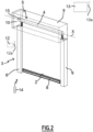
- a home automation installation 100 in accordance with the invention and installed in a building B comprising an opening 1, window or door, equipped with a screen 2 belonging to a concealment device 3, in particular a motorized roller blind.
- the concealment device 3 can alternatively be a rolling shutter, a blind with adjustable slats, or even a roll-up door.
- the present invention applies to all types of concealment device comprising a motorized rotating winding shaft.
- the screen 2 of the concealment device 3 is wound on a winding shaft 4, provided in the form of a winding tube, driven by a motorized drive device 5.
- the screen 2 is movable between a rolled up position, particularly high, and an unrolled position, particularly low.
- the motorized drive device 5 comprises an electromechanical actuator 11, in particular of the tubular type, making it possible to rotate the winding tube 4 so as to unwind or roll up the screen 2 of the concealment device 3.
- the concealment device 3 comprises the winding tube 4 for rolling up the screen 2.
- the electromechanical actuator 11 is inserted into the winding tube 4.
- the electromechanical actuator 11 and the winding tube 4 are both positioned coaxially along a longitudinal axis so that the electromechanical actuator 11 can be inserted into the winding tube 4 when assembling the concealment device 3.
- the screen 2 of the rolling shutter 3 is formed by a canvas, which is attached by one end to the winding tube and by the other end to a weighted bar 8.
- the high rolled up position of the screen corresponds to the position of the weighted bar at the level of the winding tube and the low unrolled position corresponds to the position of the weighted bar 8 of the screen 2 at the level of the threshold 7 of the opening 1.
- the deployment of the screen can be guided by slides 6.
- the winding tube 4 can be placed inside a box 9 or be visible.
- the winding tube 4 is movable in rotation relative to a support 10, such as a cheek, of the box 9.
- the motorized drive device 5 is controlled by a control unit.
- the control unit can be, for example, a local control unit 12, where the local control unit 12 can be connected in a wired or non-wired connection with a central control unit 13.
- the control unit 12 is shown here in radio version with a 12a antenna.
- the central control unit 13 controls the local control unit 12, as well as other similar local control units distributed throughout the building. It is shown here equipped with a radio antenna 13a.
- the central control unit 13 can be in communication with one or more sensors, not shown, which can be configured to determine, for example, a temperature, an interior or exterior brightness.
- a remote control 14 which may be a type of local control unit, and provided with a control keyboard, which includes selection and possibly display means, also allows a user to intervene on the electromechanical actuator 11 and/or the local control unit 12 and/or central 13.
- the motorized drive device 5 is preferably configured to execute the commands for unwinding or rolling up the screen 2 of the concealment device 3, which can be issued in particular by the remote control 14, the local control unit 12, the central control unit 13 or a sensor.
- the electromechanical actuator 11 comprises an electric motor 16.
- the electric motor 16 comprises a stator 32 and a rotor 34 positioned coaxially around the longitudinal axis or axis of rotation X.
- Means for controlling the electromechanical actuator 11, allowing the movement of the screen 2 of the concealment device 3, are constituted by at least one electronic control unit 15.
- This electronic control unit 15 is capable of putting in operation the electric motor 16 of the electromechanical actuator 11 and, in particular, to allow the supply of electrical energy to the electric motor 16.
- the electronic control unit 15 controls, in particular, the electric motor 16, so to open or close screen 2, as described previously.
- the electronic control unit 15 also comprises an order reception module 15a, in particular radio orders transmitted by an order transmitter, such as the remote control 14, intended to control the electromechanical actuator 11.
- the control module reception of orders 15a can also allow the reception of orders transmitted by wired means.
- the electronic control unit 15 is arranged inside a casing 17 of the electromechanical actuator 11.
- the means for controlling the electromechanical actuator 11 comprise hardware and/or software means.
- the hardware means may include at least one microcontroller 27.
- the electromechanical actuator 11 is supplied with electrical energy by a building electrical supply network, for example by the alternating sector network or by a direct current bus, or by means of a battery not shown, which can be recharged , for example, by a photovoltaic panel.
- the electromechanical actuator 11 comprises an electrical power cable 18 allowing its supply of electrical energy from the sector's electrical supply network.
- the electromechanical actuator 11 is intended to be placed in a U-shaped rail and intended to rotate a winding shaft on which cords associated with the screen wind.
- the casing 17 of the electromechanical actuator 11 is preferably cylindrical in shape.
- the casing 17 can be made of a metallic material.
- the material of the casing of the electromechanical actuator is in no way limiting and may be different, it may in particular be plastic.
- the electromechanical actuator 11 also comprises a reduction gear 19, in particular an epicyclic gear reducer and an output shaft 20.
- the electric motor 16 and the reduction gear 19 are arranged inside the casing 17 of the electromechanical actuator 11.
- the output shaft 20 of the electromechanical actuator 11 is arranged inside the winding tube 4 and, at least in part, outside the casing 17 of the electromechanical actuator 11.
- the output shaft 20 of the electromechanical actuator 11 is coupled by a connecting accessory 30 to the winding tube 4, in particular a connecting accessory in the form of a wheel.
- the electromechanical actuator 11 also comprises a torque support 21, mounted at one end of the casing 17 opposite the output shaft 20 and closing the end of the casing 17.
- the casing 17 and the torque support 21 are fixed in rotation relative to each other.
- the torque support 21 of the electromechanical actuator 11 is fixed to the support 10 of the trunk 9 of the concealment device 3.
- the torque support 21 is also called “fixed point” of the electromechanical actuator 11.
- the electromechanical actuator 11 also comprises a crown-bearing 31 mounted on the casing 17 and free to rotate relative to the casing 17.
- the crown-bearing 31 is fixed in rotation to the winding tube 4, so that the crown-bearing 31 provides a rotational bearing function for the winding tube 4 on the casing 17, close to the torque support 21.
- the actuator may also include devices not shown for suspending the motor or the assembly consisting of the electric motor 16 and the gear reduction device 19.
- These suspension devices are for example known from the application EP1727959A1 and make it possible to limit the transmission of vibrations, generated at this assembly, to the closure or solar protection installation and therefore to limit the noise generated during operation of the electromechanical actuator 11.
- These suspension devices are at the origin of an elasticity within the electromechanical actuator, between the torque support 21 and the rotary output shaft 20. They therefore make it possible to introduce a controlled angular deformation, around the axis the torque support 21 and the rotary output shaft 20 and thus facilitate the implementation of the obstacle detection method described below.
- the electric motor 16 is of the electronically commutated brushless type, called “BLDC” (acronym for the English term BrushLess Direct Current) or, more generally, of the permanent magnet synchronous motor type, called “PMSM” (acronym for the English term Permanent Magnetic Synchron Motor).
- BLDC electronically commutated brushless type
- PMSM permanent magnet synchronous motor type
- the rotor 34 of the electric motor 16 comprises a rotor body provided with magnetic elements surrounded by the stator 32.
- the magnetic elements are permanent magnets.
- the stator 32 of the electric motor 16 comprises a stator core comprising pole elements distributed over the periphery of the stator 32.
- the pole elements are also called teeth.
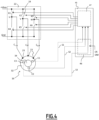
- the stator 32 of the electric motor 16 comprises windings 23, in this case three, electrically connected to each other, as illustrated schematically in the Figure 4 .
- the windings 23 are positioned around the pole elements of the stator 32. More precisely, each pole element is surrounded by a winding 23 which is specific to it.
- the windings 23 are connected together so that when a current flows through them, they produce a rotating electromagnetic field which causes the rotor 34 to rotate.
- the electronic control unit 15 of the electromechanical actuator 11 comprises a circuit not shown for rectifying the alternating voltage of the electrical power supply network and a power supply module 22.
- the power supply module 22 is thus electrically connected to a DC voltage source +Vbus.
- the value of the direct voltage +Vbus is defined in relation to a reference voltage Gnd.
- the circuit for rectifying the alternating voltage of the electrical supply network can be external to the electromechanical actuator 11.
- the electrical power module 22 supplies electrical energy, sequentially, to the windings 23, so as to produce the rotating electromagnetic field causing the rotation of the rotor 34 of the electric motor 16.
- the power supply module 22 includes switches 24 making it possible to provide the sequential power supply to the windings 23.
- the switches 24 of the power supply module 22 are “MOSFET” type transistors (acronym for the Anglo-Saxon term Metal Oxide Semiconductor Field Effect Transistor), and there are six of them. They are identified by the references K1, K2, K3, K4, K5 and K6 on the Figure 4 .
- switches 24 of the power supply module and their number are in no way limiting.
- the switches 24 of the power supply module 22 may be “IGBT” type transistors (acronym for the Anglo-Saxon term Insulated Gate Bipolar Transistor).
- the electronic control unit 15 of the electromechanical actuator 11 also comprises sensors C1, C2, C3, positioned fixedly relative to the stator 32, preferably integrated therein.
- these sensors 18, 20 are Hall effect sensors with binary output.
- these sensors are positioned at 60° or 120° relative to each other around the axis electric motor 16 around the axis X and therefore an equivalent angular position of the output shaft 20 of the electromechanical actuator 11. This angular position of the rotor is intended in particular for controlling the switches 24.
- the number of sensors C1, C2, C3 is not necessarily equal to 3. There may also be no physical sensor C1, C2 or C3.
- the number of sensors can also be 1, 2 and 4 or more. In this case, the distribution of the sensor(s) around the X axis is adapted according to their number.
- a control unit 45 is in particular configured to control the electric motor 16 so as to set the screen 2 in motion to move it to a desired position.
- control unit 45 is configured to control the electric motor 16 using a pulse width modulation (or PWM) technique.
- the control unit 45 is in particular configured to control the electric motor 16 taking into account the angular position of the rotor 32, for example measured by the sensor(s) C1, C2, C3.
- the output signals S1, S2, S3 of the sensors C1, C2, C3 feed an algorithm for generating control signals, executed by the module 45, which makes it possible to determine the times at which the control signals are sent to the module. switching 22.
- the control unit comprises in particular a control circuit 46, comprising a microprocessor.
- the control circuit 46 may include an order reception input, to receive position instructions CP and/or movement orders OM, such as, for example, opening or closing the screen 2, coming for example from a local control unit 12, a remote control 14, a central control unit 13 or an installation sensor 100.
- the control circuit 46 may include a signal output interface 47, which emits the control signals for controlling the switches 24 identified by the references K1 to K6.
- the electrical power supply module 22 and the control unit 45 form part, at least partially, of the electronic control unit 15 of the electromechanical actuator 11.
- the electronic control unit 15 of the electromechanical actuator 11 comprises a device for detecting obstacles and limit switches when the screen 2 is rolled up and when this screen is unrolled. This device will be described in more detail below, with reference to the figures 4 to 7 .
- the electromechanical actuator 11 comprises a first position detection device 36, adapted to define an angular position of the rotor 34 around the axis embodiment shown in Figure 4 , the first position detection device comprises the sensors C1, C2, C3, positioned fixedly relative to the stator 32.
- the first detection device 36 comprises, on the one hand, a wheel 46 called an encoder wheel, comprising magnetized sectors 48 whose polarity is alternated on the circumference 50 of the encoder wheel 46.
- the encoder wheel 46 may comprise two magnetized sectors or more.
- the encoder wheel 46 cooperates with the rotor 34 by being rotated by the rotor 34.
- the encoder wheel 46 is mounted on one end of the rotor 34, protruding axially from the stator 32 and located opposite the output shaft 20 of the electromechanical actuator 11.
- the first position detection device 36 comprises, on the other hand, a first sensor device 52, comprising one or more magnetic sensors, for example Hall effect or magneto-resistive, positioned opposite the encoder wheel 46.
- the first sensor device 52 is also part of the control unit or is connected to it and may include the sensors C1, C2, C3.
- the signals 54 from the first sensor device 52, generated by the rotation of the encoder wheel 46 facing the first sensor device 52, are transmitted to the microcontroller 27 of the electronic control unit 15 and the angular displacement of the rotor 34 and/or or the angular position of the rotor 34 is defined from these signals 54.
- the first position detection device 36 comprises hardware and software means for determining the position of the rotor 34 without a specific physical sensor measuring the rotation of the rotor.
- Such hardware and software means are, for example, described in the application WO2014207387A1 .
- any other type of electric motor is also possible, with suitable power supply and control, as well as a first corresponding position detection device 36.
- the first position detection device comprises means for counting the brush passages at the collector during rotation of the motor.
- the electric motor is an asynchronous motor powered by alternating current
- the first position detection device comprises magnetic sensors, for example positioned at the output of the electric motor 16.
- the electromechanical actuator 11 also comprises a second position detection device 38, adapted to define an angular position of the winding shaft 4 around the axis X.
- the second position detection device 38 comprises, similarly to the first position detection device 36, a magnetized rotating element 56.
- the magnetized rotating element 56 comprises and supports discrete magnets 58, mounted on a rotating support 60 in an alternating manner, that is to say in such a way that the rotating element 56 has a radial periphery or an axial face with alternative magnetized sectors 40.
- the magnetized rotating element 56 comprises a polarized ring.
- the rotary element 56 is mounted to rotate freely relative to the torque support 21 or to the casing 17 of the electromechanical actuator 11. It is adapted to be rotated around the axis output 20 of the electromechanical actuator 11, in particular adapted to be driven in rotation by the winding shaft 4, coupled in rotation with the output shaft 20 of the electromechanical actuator 11.
- the second detection device 38 also comprises a second sensor device 64 comprising one or more magnetic sensors, for example Hall effect in one, two or three dimensions or magneto-resistive, positioned opposite the rotating element 56.
- the second sensor device 64 is also part of the electronic control unit 15 or is connected to it.
- the signals 66 from the second detection device 38, generated by the rotation of the magnetized rotating element 56 facing the second sensor device 64, are transmitted to the microcontroller 27 of the electronic control unit 15 and the position or angular displacement of the rotating element 56 is defined from these signals 66.
- the second position detection device 38 is adapted to determine the rotation around the axis thus to the rotating element 56.
- the crown-bearing 31 comprises at least two magnetic sectors 40 distributed regularly over a periphery or a face facing a magnetic sensor device 64 disposed in the casing 17 of the electromagnetic actuator 11.
- the first position detection device 36 is used in particular to determine the position of the rotor 34 with a view to controlling the electric motor 16, particularly in the case of a PMSM type motor, with electronic switching. Its precision is required to enable this control in particular.
- the arrival of the screen 2 in particular positions learned beforehand, for example extreme positions, called end positions, can be managed either by the first position detection device 36 or by the second position detection device 38. At least one of the two devices must therefore be sufficiently precise to manage the arrival in the extreme positions, according to market prerequisites, in particular to manage the visual alignment of two weighted bars 8 of two screens 2 placed side by side. side.
- a preferred embodiment of the electromechanical actuator 11 comprises a “permanent magnet synchronous” electric motor, electronically commutated, or a direct current motor with brushes and collector, in which only the second detection device 38 comprises suitable magnetic or optical sensors. to determine the angular displacement of the winding shaft.
- the arrival of the screen 2 in end-of-travel positions is managed by the second position detection device 38.
- the second position detection device 38 is used in combination with the first position detection device 36 for obstacle management.
- the two position detection devices 36, 38 may have different accuracies.
- the precision constraint is more important for the management of extreme positions, managed by only one of the two counters, than obstacle detection, based on the two position detection devices 36 and 38.
- the electronic control unit 15 comprises hardware means, such as the microcontroller 27, and software for processing data from the two position detection devices 36, 38 so as to determine from the data provided by the first detection device position 36 and by the second position detection device 38 an angular displacement value of the rotor 34 relative to the stator 32 and an angular displacement value of the winding shaft 4 relative to the casing 17 or to the torque support 21 of the electromechanical actuator 11.
- the electronic control unit 15 notably comprises a memory, not shown, for storing a current value and an original value of angular displacement and for storing an algorithm for implementing the detection method obstacle by this microcontroller 27.
- the method of detecting an obstacle opposing the movement of the screen 2 in the home automation installation 100 for closing or solar protection is implemented in the following manner.
- the method comprises a step E101 of determining an angular displacement value D ⁇ of the rotor 34 relative to the stator 32 of the electromechanical actuator 11.
- the determination step E101 comprises a sub-step of recovering the signals 54 coming respectively from the first position detection device 36.
- the method comprises a step E103 of determining an angular displacement value D ⁇ of the winding shaft 4 relative to the casing 17 or the torque support 21 of the electromechanical actuator 11.
- the determination step E103 comprises a sub-step of recovering the signals 66 coming from the second position detection device 38.
- the signals 54, 66 coming from each position detection device 36, 38 can be processed and filtered.
- a comparison signal 59 resulting from the comparison of the two signals 54 and 56 is processed and filtered. This comparison signal is represented at figure 8 .
- Signals 54 and 66 can, however, only be compared if they are related to the same time frame. Indeed, due to the different rotation speeds of the rotor 34 and the output shaft 20, or the different rotation speeds of the rotor 34 and the winding shaft 4, by interposition of the reducer 19 between them, the time markers are not the same. In other words, the angular displacements D ⁇ and D ⁇ respectively coming from the signals 54 and 66 can only be compared if one of them is related to the other by conversion using the reduction ratio as a multiplication or division factor. of the reducer 19, the latter being defined subsequently, by convention, as greater than 1.
- the signal 54 is made comparable to the signal 66 by division by the reduction ratio of the reducer 19, that is to say say that the angular displacement D ⁇ is made comparable to the angular displacement D ⁇ by dividing it by the reduction ratio R19 of the reducer 19.
- the signal 66 is made comparable to the signal 54 by multiplication by the reduction ratio of the reducer 19, that is that is, the angular displacement D ⁇ is made comparable to the angular displacement D ⁇ by multiplying it by the reduction ratio R19.
- the method comprises a step of converting E105 the angular displacement value of the rotor 34 into equivalent angular displacement data of the winding shaft 4.
- the equivalent angular displacement data is obtained by dividing or by multiplying the angular displacement value of the rotor 34 by the theoretical reduction ratio R19 of the reducer 19 of the electromechanical actuator 11.
- the conversion step can act on the angular displacement data of the winding shaft 4 or the output shaft 20, so as to convert it into equivalent angular displacement data of the rotor 34.
- the comparison between the values of angular displacement and equivalent angular displacement makes it possible to check the presence or absence of an obstacle on the path of screen 2.
- the method comprises a step E107 of determining an angular deformation DA of the kinematic chain between the electric motor 16 and the winding shaft 4 by comparison between the angular displacement values obtained at previous steps E101 and E105 or E103 and E105, in other words by analysis of the comparison signal 59 resulting from the comparison of the two signals 54 and 56.
- the method then comprises a step E109 of determining the presence of an obstacle to the movement of the screen 2 from a comparison of an angular deformation value DA determined in step E107 of the kinematic chain in relation to a predefined VS threshold value of angular deformation.
- An obstacle is considered to be present if the angular deformation determined in step E107 is greater than the predefined angular deformation threshold value VS.
- step E111 If the angular deformation value DA is greater than the threshold value VS, an alarm is activated in a step E111. Otherwise, the process resumes at step E101.
- a first option is to add a deformation element 70 to the kinematic chain between the output of the rotor 34 and the point of attachment of the winding tube 4 to the crown-bearing 31. This first option will be discussed in more detail below. below.
- a second option consists of using the elastic properties of the materials of the different components of the kinematic chain, in particular elastic properties notably in torsion, in particular when a suspension device is integrated into the electromechanical actuator, as described above .
- the response of the electromechanical actuator 11 in the event of an obstacle will be in this second option less rapid than a specifically adapted deformation element.
- a deformation element 70 can be added in the kinematic chain between the output of the rotor 34 and the point of attachment of the winding tube 4 to the crown-bearing 31.
- a deformation element 70 such as a spring device, arranged either at the level of the connecting accessory 30 of the output shaft 20 of the electromechanical actuator 11 to the winding tube 4, or at the output shaft 20 itself.
- This deformation element 70 adds elasticity to, or reduces the stiffness of, the kinematic chain between the parts 34 and 4, which makes it possible to observe differences in angular position more easily and quickly. measured by the first position detection device 36 and by the second position detection device 38.
- the output shaft 20 comprises two distinct parts: an upstream part 120 of the output shaft 20 is fixed in rotation with the output of the reducer 19 and a downstream part 140 adapted for fixing to the winding shaft 4 , for example by means of a connecting accessory 30.
- the upstream part 120 comprises a body 121 from which a rod 125 extends.
- the body 121 also comprises a grooved internal recess 123, adapted to cooperate with a shaft of outlet not shown of the reducer 19, opposite the rod 125.
- At the periphery of the body 121 there is also a longitudinal groove 124.
- a semi-cylindrical block 126 also extends from the body 121.
- the block 126 comprises an exterior surface 130 and two abutment surfaces 131, 132, on either side of the block 126, extending the exterior surface 130 in the direction of the rod 125.
- the semi-cylindrical block 126 extends partially around the rod 125, being integral with the rod 125.
- the downstream part 140 comprises a first end 141 which comprises on its outer periphery a longitudinal groove 144.
- a second end 142 of the downstream part 140 is provided with grooves 146 and clips 143 on its outer periphery, suitable for fixing the connecting accessory 30 on this downstream part 140 by clipping.
- the downstream part 140 is mounted in rotation on the upstream part 120, for example by cooperation of the rod 125 of the upstream part 120 and a first corresponding cylindrical recess 145, internal to the downstream part 140 and formed partly in the first end 142.
- the two upstream 120 and downstream 140 parts are held in position relative to each other by an elastic device 160, such as a helical spring, a first folded tab 161 of which is blocked in the groove 124 of the upstream part 120 and of which a second folded tab 162 is blocked in the groove 144 provided on the downstream part 140.
- the turns of the spring 160 are held, on the internal diameter of the spring in particular, by the external surface 130 of the upstream part and by a half - corresponding cylinder 154 on the downstream part 140.
- the first and last turns of the spring are held axially on ramps 164, only one of which is visible at the Figure 12 .
- the two upstream 120 and downstream 140 parts are also held axially relative to each other by means of a screw 170, provided with a head 172 and a threaded rod 173, the screw 170 not preventing the rotation of the downstream part 140 relative to the upstream part 120.
- the screw head 172 is for this purpose free to rotate relative to the downstream part 140.
- the screw is introduced through a second cylindrical recess 147 opening onto the first end 141 of the downstream part 140 and joining the first cylindrical recess 145 via a passage circular 148 whose diameter is slightly greater than the diameter of the threaded rod 173 of the screw 170, but less than the diameter of the screw head 172.
- the first cylindrical recess 145 is partially extended axially by a semi-cylindrical block 149.
- the block 149 also comprises an exterior surface 150 and two abutment surfaces 151, 152, on either side of the block and joining the exterior surface 150 and an interior wall 153 as an extension of the cylindrical recess 145.
- the semi-cylindrical block 126 of the upstream part 120 finds itself facing the cylindrical block 149 of the downstream part 140.
- the abutment surfaces 131, 132 and 151, 152 are not in contact at rest. A space remains between the facing stop surfaces.
- the angle ⁇ formed by the surfaces 131 and 132 between them within the block 126 and/or the angle ⁇ formed by the surfaces 151 and 152 between them within the block 149 is strictly less than 180°.
- the sum of angles ⁇ and ⁇ is strictly less than 360°.
- the elastic device 160 is constrained in a torsional direction.
- the elastic device 160 is dimensioned so that the abutment surfaces 131 or 132 only come into contact with the abutment surfaces 151 or 152 beyond a torque greater than a nominal operating torque of the electromechanical actuator 11.
- the lifting of the weight of the weighted bar 8 due to the presence of an obstacle in its path relieves the stress on the spring 160 and allows angular deformation of the deformation element 70.
- deformation element 70 being placed on the kinematic chain between the first position detection device 36 and the second position detection device 38, the angular variation observed between the two signals coming from these position detection devices makes it possible to observe, reliably, the presence of an obstacle.
- the deformation element 70 comprises a torsion bar mounted between the output of the reducer 19 and the output shaft 20.
- This deformation element 70 in the form of a torsion bar transmits the motor torque to the winding shaft 4 , in the same way as the deformation element described above which includes a spring.
- the output shaft 20 comprises two distinct parts.
- An upstream part 220 of the output shaft 20 is fixed in rotation with the output of the reducer 19, by cooperation of shapes between a internal grooved recess 223 and the output shaft of the reducer 19.
- a downstream part 240 is adapted for attachment to the winding shaft 4, for example by means of a connecting accessory, such as that shown in Figure 3 with the reference 30.
- the two upstream 220 and downstream 240 parts operate in a manner similar to the previous embodiment, in the sense that they are held in position relative to each other by an elastic device 260, which is here made in the form of a torsion bar.
- the two upstream 220 and downstream 240 parts include abutment surfaces 231, 232 (not visible on the Figure 13 ) and 251, 252 which are opposite each other when the output shaft 20 is assembled, with a space remaining between the facing abutment surfaces.
- the angle formed by the surfaces 231 and 232 between them and/or the angle formed by the surfaces 251 and 252 between them is strictly less than 180°.
- the torsion bar 260 is held fixed in rotation by its ends with the upstream part 220 and with the downstream part 240 in particular by cooperation of shapes.
- the torsion bar 260 comprises a central part 263, generally cylindrical, and two upstream ends 261 and downstream 262 of polygonal, square or hexagonal shape for example.
- a first fixing plate 280 comprises a central recess 282 complementary to the upstream end 261 of the torsion bar 260 and an external periphery 284 complementary to the internal grooved recess 223 of the upstream part 220.
- a second fixing plate 290 comprises a central recess 292 complementary to the downstream end 262 of the torsion bar 260 and an external periphery 294 complementary to a non-circular internal recess 247 of the downstream part 240.
- the polygonal ends 261 and 262 of the torsion bar 260 come be housed without the possibility of rotation in the fixing plates 280 and 290, themselves being fixed in rotation in the upstream 220 and downstream 240 parts.
- the torsion bar 260 is also fixed axially by screws 270, aimed at the ends 261 and 262 of the torsion bar and tightening the fixing plates 280 and 290 against the central cylindrical part 263 of the torsion bar 260.
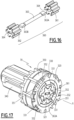
- the deformation element 70 comprises an elastic device also produced here in the form of a torsion bar 360 mounted between the output of the reducer 19 and the output shaft 20.
- This deformation element 70 transmits the engine torque towards the winding shaft 4, in the same way as the deformation element of the figure 13 .
- An upstream part 320 of the output shaft 20 is fixed in rotation with the output of the reducer 19, by cooperation of shapes between a grooved internal recess 323 of this upstream part and the output shaft of the reducer 19.
- a downstream part 340 of the output shaft 20 is adapted for attachment to the winding shaft 4, for example by means of a connecting accessory, such as that shown in Figure 3 with the reference 30.
- Two rings 330 and 350 are respectively mounted around the upstream 320 and downstream 340 parts. These rings are secured together by elastic clipping and/or shape cooperation between tongues, only one of which is visible at the Figure 14 with the reference 353, which extend from the ring 350 and which cover the external reliefs 332 of the ring 330 when the rings are assembled together.
- the rings 330 and 350 make it possible to maintain and center the deformation element 70 in the casing or the winding tube defined as in the first embodiment.
- the two upstream 320 and downstream 340 parts respectively comprise abutment surfaces 331, 332 and 351, 352 which are opposite each other when the output shaft 20 is assembled, as visible in the Figure 17 , with spaces remaining between the facing abutment surfaces.
- the widths of these spaces measured between the abutment surfaces 331 and 351 or 332 and 352 in a direction ortho-radial to the axis upstream 320 and downstream 340 around the X axis.
- the torsion bar 360 is generally in the shape of a dumbbell and comprises a central rod 363, preferably metallic, and two pinions 361 and 362, made of synthetic material or metal, which respectively form the upstream and downstream ends of the torsion bar. twist.
- the pinions 361 and 362 are respectively configured to engage with internal teeth 321 of the upstream part 320 and with internal teeth 342 of the downstream part 340.
- the bar 360 works in torsion in the event of relative movement of the upstream parts and downstream 320 and 340, rotating around the axis X.
- the central rod is provided with two flattened ends 363A and 363B configured to be received in correspondingly shaped housings 364 provided in the center of the gears 361 and 362, which allows torque transmission between the central rod and the gears.
- the housings 364 of the two pinions 361 and 362 also have the same shape.
- the method may optionally include a preliminary learning step E100.
- the learning step E100 may include a step of learning an angular variation threshold. Alternatively, the angular variation threshold between the two Detection devices can be chosen fixed.
- the learning step may include a step of learning a detection time. The learning step E100 makes it possible to adapt the obstacle detection to the installation 100, or even to the position of the screen 2 over its course.
- This learning step E100 can take place during the installation of the motorized concealment device within the installation 100.
- the threshold(s), and/or the detection time of the obstacle may be be determined by learning when carrying out a learning cycle, that is to say a complete opening-closing cycle without obstacle.
- a learning cycle that is to say a complete opening-closing cycle without obstacle.
- one or more maximum deviations that is to say local maxima of the angular deformation value DA of the kinematic chain during the cycle, are determined and recorded, the angular deformation being defined during a step similar to step E107.
- This or these threshold values are integrated into the algorithms for filtering and analyzing the values of position detection devices.
- the threshold can also be defined as a progressive variable threshold, with a Relatively slow reaction time.
- the threshold can also be defined as a progressive variable threshold, with a Relatively slow reaction time.
- sudden angular variations for example linked to the passage of hard points of the weighted bar 8 in the slides 6, with a relatively rapid reaction time.
- Threshold values can be defined based on values measured during learning cycles and a safety margin value.
- the learning step E100 can also be repeated during the life of the product, particularly automatically. Several learning cycles may be necessary before modifying previously saved values. In particular, the threshold values, detection sensitivity or detection time can be adjusted during these learning cycles, to determine the value most suited to the installation.
- the comparison signal 59 obtained from the two position detection devices 36 and 38 can be processed and filtered according to conventional methods, in particular by static or dynamic filtering.
- filtering parameters can be defined and adjusted: the number F of filter values, the index deviation p compared to the previous value, the detection threshold S in counter value.
- the comparison signal 59 can be filtered according to a simple average for example or according to other more complex filtering and on F values.
- An algorithm with significant filtering, or dynamic filtering makes it possible to eliminate high and low frequencies and makes it possible to determine a measure of relative deviation.
- the filtering can be more limited. This is called static filtering.
- the deviation measurement can be determined in absolute value.
- Obstacle detection is triggered after a predefined trigger time.
Landscapes
- Engineering & Computer Science (AREA)
- Structural Engineering (AREA)
- Power Engineering (AREA)
- Architecture (AREA)
- Civil Engineering (AREA)
- Databases & Information Systems (AREA)
- Operating, Guiding And Securing Of Roll- Type Closing Members (AREA)
Claims (15)
- Verfahren zum Erkennen eines Hindernisses, das der Bewegung eines Schirms (2) in einer Hausautomatisierungsanlage (100) zum Schließen oder zum Sonnenschutz entgegensteht, die einen elektromechanischen Aktuator (11) umfasst, der die Bewegung eines Schirms (2) antreibt, wobei der elektromechanische Aktuator (11) eine Drehmomentstütze (21), ein Gehäuse (17), eine Abtriebswelle (20), einen Elektromotor (16) mit einem Stator (32) und einem Rotor (34) umfasst, wobei die Anlage (100) eine Wickelwelle (4) umfasst, die den Schirm (2) in Rotation versetzt, und ein Verbindungszubehör (30) zwischen der Abtriebswelle (20) des elektromechanischen Aktuators (11) und der Wickelwelle (4), wobei das Verfahren die folgenden Schritte umfasst:- (E101) Bestimmen eines Wertes für die Winkelverschiebung (Dθ) des Rotors (34) in Bezug auf den Stator (32) des elektromechanischen Aktuators (11),- (E103) Bestimmen eines Wertes für die Winkelverschiebung (DΦ) der Wickelwelle (4) in Bezug auf das Gehäuse (17) oder die Drehmomentstütze (21) des elektromechanischen Aktuators (11),- (E107) Bestimmen einer Winkelverformung (DA) des Antriebsstrangs zwischen dem Elektromotor (16) und der Wickelwelle (4) durch Vergleich zwischen diesen beiden Werten der Winkelverschiebung,- (E109) Bestimmen des Vorhandenseins eines Hindernisses für die Bewegung des Schirms (2) aus einer Winkelverformung, die größer als ein vordefinierter Wert (VS) der Winkelverformung ist.
- Verfahren nach Anspruch 1, dadurch gekennzeichnet, dass es mindestens einen Schritt (E105) zur Umwandlung von Folgendem umfasst:(a) des Wertes der Winkelverschiebung (Dθ) des Rotors (34) in eine äquivalente Winkelverschiebungsangabe der Wickelwelle (4) oder(b) des Wertes der Winkelverschiebung (DΦ) der Wickelwelle (4) in Bezug auf das Gehäuse (17) oder die Drehmomentstütze (21) des elektromechanischen Aktuators (11) in eine äquivalente Winkelverschiebungsangabe des Rotors (34).
- Verfahren nach dem vorhergehenden Anspruch, dadurch gekennzeichnet, dass die äquivalente Winkelverschiebungsangabe erhalten wird, indem der Wert der Winkelverschiebung (Dθ) des Rotors (34) durch das theoretische Übersetzungsverhältnis (R19) eines Getriebes (19) des elektromechanischen Aktuators (11) geteilt wird, wobei das Übersetzungsverhältnis eine Zahl größer als 1 ist, oder umgekehrt durch Multiplizieren des Winkelverschiebungswertes (DΦ) der Wickelwelle (4) mit dem theoretischen Untersetzungsverhältnis des Getriebes (19) des elektromechanischen Aktuators (11).
- Verfahren nach einem der Ansprüche 3 oder 4, dadurch gekennzeichnet, dass es einen Schritt (E109) des Verarbeitens und Filterns eines Vergleichssignals (59) umfasst, das aus dem Signal (54) der Winkelverschiebung des Rotors (34) und dem Signal (56) der Winkelverschiebung der Wickelwelle (4) erhalten wird.
- Verfahren nach einem der vorhergehenden Ansprüche, dadurch gekennzeichnet, dass es einen Schritt des Lernens (E100) des vordefinierten Werts (VS) der Winkelverformung in Abhängigkeit von Daten der Winkelverformungsabweichung und/oder der Auslösezeit dieser Abweichungen umfasst, die während eines Lernzyklus gemessen wurden.
- Verfahren nach einem der vorhergehenden Ansprüche, bei dem das Erreichen extremer Positionen des Schirms (2) durch Vergleich des Wertes der Winkelverschiebung (DΦ) der Wickelwelle (4) mit einem vordefinierten Verschiebungswert verwaltet wird.
- Elektromechanischer Aktuator (11) mit einer Drehmomentstütze (21), einem Gehäuse (17), einem Elektromotor (16) mit einem Stator (32) und einem Rotor (34) und einer Abtriebswelle (20), die über ein Verbindungszubehör (30) mit einer Wickelwelle (4) in Drehungseingriff steht, wobei der elektromechanische Aktuator (11) dadurch gekennzeichnet ist, dass er ferner eine erste Positionserfassungsvorrichtung (36) umfasst, die dazu geeignet ist, eine Winkelposition des Rotors (34) zu bestimmen, und eine zweite Positionserfassungsvorrichtung (38), die dazu geeignet ist, eine Winkelposition der Wickelwelle (4) zu bestimmen, die mit der Abtriebswelle (20) in Drehungseingriff steht, und eine elektronische Steuereinheit (15), die dazu ausgelegt ist, die von den beiden Positionserfassungsvorrichtungen (36, 38) stammenden Daten so zu verarbeiten, dass das Verfahren nach einem der vorhergehenden Ansprüche durchgeführt wird.
- Elektromechanischer Aktuator (11) nach dem vorhergehenden Anspruch, dadurch gekennzeichnet, dass die Wickelwelle (4) ein Wickelrohr ist, in das der elektromechanische Aktuator (11) zumindest teilweise eingesetzt ist, wobei dieser einen Lagerkranz (31) umfasst, der um das Gehäuse (17) in Bezug auf die Drehmomentstütze (21) drehbar ist und mit dem Wickelrohr (4) in Drehungseingriff steht, wobei die zweite Positionserfassungsvorrichtung (38) dazu ausgelegt ist, die Drehung des Lagerkranzes (31) in Bezug auf die Drehmomentstütze (21) des elektromechanischen Aktuators zu bestimmen.
- Elektromechanischer Aktuator (11) nach dem vorhergehenden Anspruch, dadurch gekennzeichnet, dass der Lagerkranz (31) mindestens zwei magnetische Sektoren (40) umfasst, die regelmäßig auf einem Umfang oder einer Fläche verteilt sind, die einer in dem Gehäuse (17) des elektromagnetischen Aktuators (11) angeordneten Magnetsensorvorrichtung (64) gegenüberliegt.
- Elektromechanischer Aktuator (11) nach einem der Ansprüche 7 bis 9, dadurch gekennzeichnet, dass er ein Verformungselement (70) umfasst, das im Antriebsstrang zwischen dem Rotor (34) und der Wickelwelle (4) angeordnet ist und einen stromaufwärtigen Teil (120; 220; 320) und einem stromabwärtigen Teil (140; 240; 340), die relativ zueinander drehbar sind und eine elastische Vorrichtung (160; 260; 360) umfasst, die der Drehbewegung des stromaufwärtigen (120; 220; 320) und des stromabwärtigen (140; 240; 340) Teils entgegenwirkt.
- Elektromechanischer Aktuator (11) nach dem vorhergehenden Anspruch, dadurch gekennzeichnet, dass die elastische Vorrichtung (70) einen Torsionsstab (260; 360) umfasst.
- Elektromechanischer Aktuator (11) nach dem vorhergehenden Anspruch, dadurch gekennzeichnet, dass die elastische Vorrichtung (70) eine zentrale Stange (263, 363) und zwei Ritzel (284, 294; 361, 362) umfasst, die an den Enden (261, 262; 363A, 363B) der zentralen Stange angebracht sind und mit Innenverzahnungen (223, 247; 321, 342) der stromaufwärts (220, 320) und stromabwärts (240, 340) gelegenen Teile in Eingriff stehen.
- Elektromechanischer Aktuator (11) nach einem der Ansprüche 7 bis 12, dadurch gekennzeichnet, dass er einen elektronisch kommutierten Permanentmagnet-Synchron-Elektromotor (16) umfasst.
- Elektromechanischer Aktuator (11) nach einem der Ansprüche 7 bis 13, dadurch gekennzeichnet, dass nur die zweite Erfassungseinrichtung (38) von den beiden Winkelstellungserfassungseinrichtungen (36, 38) eine physikalische Sensoreinrichtung (64), insbesondere Magnetsensoren zur Bestimmung der Winkelstellung umfasst.
- Schließ- oder Sonnenschutzanlage (100) mit einem Schirm (2), einer Wickelwelle (4) und einem elektromechanischen Aktuator (11), der mit der Wickelwelle (4) in Drehungseingriff steht, wobei der elektromechanische Aktuator (11) einem der Ansprüche 7 bis 14 entspricht.
Applications Claiming Priority (2)
| Application Number | Priority Date | Filing Date | Title |
|---|---|---|---|
| FR2002756A FR3108459B1 (fr) | 2020-03-20 | 2020-03-20 | Procédé de détection d’un obstacle, actionneur électromécanique et installation de fermeture ou de protection solaire |
| PCT/EP2021/057120 WO2021186051A1 (fr) | 2020-03-20 | 2021-03-19 | Procédé de détection d'un obstacle, actionneur électromécanique et installation de fermeture ou de protection solaire |
Publications (2)
| Publication Number | Publication Date |
|---|---|
| EP4121626A1 EP4121626A1 (de) | 2023-01-25 |
| EP4121626B1 true EP4121626B1 (de) | 2024-04-24 |
Family
ID=70457040
Family Applications (1)
| Application Number | Title | Priority Date | Filing Date |
|---|---|---|---|
| EP21712532.7A Active EP4121626B1 (de) | 2020-03-20 | 2021-03-19 | Verfahren zur erkennung eines hindernisses, elektromechanischer aktuator und schliess- oder sonnenschutzeinheit |
Country Status (5)
| Country | Link |
|---|---|
| US (1) | US11840885B2 (de) |
| EP (1) | EP4121626B1 (de) |
| CN (1) | CN115298409B (de) |
| FR (1) | FR3108459B1 (de) |
| WO (1) | WO2021186051A1 (de) |
Families Citing this family (3)
| Publication number | Priority date | Publication date | Assignee | Title |
|---|---|---|---|---|
| US12237800B2 (en) * | 2019-12-20 | 2025-02-25 | Nien Made Enterprise Co., Ltd. | Electric window covering, control device thereof and control method thereof |
| FR3131139A1 (fr) | 2021-12-17 | 2023-06-23 | Somfy Activites Sa | Dispositif et procédé de contrôle d’un moteur électrique en vue de réduire un bruit de fonctionnement |
| CN116446777B (zh) * | 2023-04-28 | 2024-08-30 | 东莞市歌声美实业有限公司 | 自动及手动双模式卷帘门 |
Family Cites Families (42)
| Publication number | Priority date | Publication date | Assignee | Title |
|---|---|---|---|---|
| US4055789A (en) * | 1975-12-31 | 1977-10-25 | Donald J. Dimmer | Battery-operated motor with back EMF charging |
| FR2525832B1 (fr) * | 1982-04-23 | 1986-05-09 | Carpano & Pons | Dispositif de commande d'un moteur electrique |
| FR2573551B1 (fr) * | 1984-11-16 | 1987-02-06 | Somfy | Dispositif de commande pour volet roulant ou similaire a lames orientables |
| US5760558A (en) * | 1995-07-24 | 1998-06-02 | Popat; Pradeep P. | Solar-powered, wireless, retrofittable, automatic controller for venetian blinds and similar window converings |
| DE19706209B4 (de) * | 1996-11-09 | 2004-05-06 | Becker-Antriebe Gmbh | Vorrichtung zur Steuerung, insbesondere Endabschaltung einer motorischen Antriebsvorrichtung einer Wickelwelle eines Rolladens, Garagentors o. dgl. |
| US6392374B1 (en) * | 1998-02-10 | 2002-05-21 | Somfy | Device for control of an electric motor driving a moving object |
| FR2780089B1 (fr) * | 1998-06-22 | 2000-08-25 | Somfy | Dispositif de commande d'un moteur d'entrainement d'un volet roulant |
| FR2780748B1 (fr) * | 1998-07-01 | 2000-09-08 | Somfy | Store motorise avec automatisme de securite |
| FR2814298B1 (fr) * | 2000-09-15 | 2002-12-06 | Somfy | Procede de commande d'un moteur electrique entrainant un corps en translation |
| TW448979U (en) | 2001-02-19 | 2001-08-01 | Chen Tai Shan | Control and obstacle sensor device for curtain rolling machine |
| FR2858996B1 (fr) * | 2003-08-18 | 2005-10-14 | Somfy | Procede d'initialisation d'un volet roulant |
| US6979962B2 (en) | 2004-03-16 | 2005-12-27 | Somfy Sas | Internally suspended motor for powered window covering |
| JP2006085369A (ja) | 2004-09-15 | 2006-03-30 | Sony Corp | 移動体装置及びその制御方法 |
| FR2877109B1 (fr) * | 2004-10-25 | 2007-01-19 | Somfy Sas | Procede de perfectionnement d'un ecran motorise et ecran motorise pour sa mise en oeuvre |
| ITTV20050169A1 (it) * | 2005-11-07 | 2007-05-08 | Nice Spa | Dispositivo di sicurezza per avvolgibili, tende solari, cancelli o simili. |
| EP2167776B1 (de) * | 2007-06-07 | 2010-09-08 | VKR Holding A/S | Wickelwelle mit Rohrmotor und elektronischem Bewegungssensor |
| ITVE20070089A1 (it) | 2007-11-26 | 2009-05-27 | Master S R L Unipersonale | Modulo adattatore con molle di compensazione per motori tubolari idonei alla movimentazione di dispositivi di protezione ambientale. |
| FR2925932B1 (fr) * | 2007-12-26 | 2011-08-26 | Somfy Sas | Procede de reglage d'une installation de protection solaire motorisee ne comprenant pas de butee franche. |
| FR2928401B1 (fr) | 2008-03-06 | 2011-12-23 | Deprat Jean Sa | Procede de commande d'un dispositif de fermeture et d'ouverture a commande filaire, tel que notamment un volet roulant |
| FR2941991B1 (fr) | 2009-02-06 | 2011-02-25 | Somfy Sas | Procede de detection de la presence d'un element entre un seuil d'une ouverture et une extremite d'un ecran domotique motorise. |
| JP5264617B2 (ja) * | 2009-05-21 | 2013-08-14 | 伊東電機株式会社 | 巻き取り用駆動装置、並びに、巻き取り装置 |
| FR2946997B1 (fr) * | 2009-06-23 | 2011-07-08 | Somfy Sas | Actionneur electrique d'entrainement d'un ecran domotique |
| US20120137585A1 (en) * | 2010-12-03 | 2012-06-07 | The Chamberlain Group, Inc. | Rolling Door Ballooning Monitor Apparatus and Method |
| PL2538015T3 (pl) | 2011-06-20 | 2014-08-29 | Nice Spa | Elastyczne sprzęgło kłowe do napędu rurowego rolowanej żaluzji |
| FR2978791B1 (fr) * | 2011-08-05 | 2013-09-20 | Somfy Sas | Procede de commande d'un ecran et actionneur adapte pour un tel procede |
| FR2978790B1 (fr) * | 2011-08-05 | 2013-08-30 | Somfy Sas | Procede de commande d'un ecran et actionneur adapte pour un tel procede |
| FR2978792B1 (fr) * | 2011-08-05 | 2013-09-20 | Somfy Sas | Procede de configuration et de commande d'un groupe d'ecrans et actionneur adapte pour un tel procede de commande |
| ITTV20120183A1 (it) | 2012-09-26 | 2014-03-27 | Nice Spa | Freno bidirezionale |
| CA2828819C (en) * | 2012-10-03 | 2020-03-10 | Hunter Douglas Inc. | Methods and apparatus to control an architectural opening covering assembly |
| FR2999640B1 (fr) | 2012-12-19 | 2015-06-05 | Somfy Sas | Actionneur electromecanique, installation de fermeture ou de protection solaire comprenant un tel actionneur et procede de controle d'un tel actionneur |
| FR3006706B1 (fr) * | 2013-06-06 | 2015-06-05 | Somfy Sas | Detection de la position d’un tambour d’enroulement accouple a un moteur par l’intermediaire d’un element souple amortisseur |
| FR3007911B1 (fr) * | 2013-06-27 | 2015-06-26 | Somfy Sas | Dispositif de controle d’un moteur |
| FR3015545B1 (fr) | 2013-12-20 | 2018-02-16 | Somfy Sas | Dispositif d'entrainement motorise d'un tube d'enroulement pour un ecran appartenant a un dispositif d'occultation |
| FR3024176B1 (fr) | 2014-07-25 | 2016-08-05 | Somfy Sas | Procede de controle d'un actionneur d'enroulement, actionneur d'enroulement configure pour un tel procede et installation de fermeture ou de protection solaire comprenant un tel actionneur |
| FR3024747B1 (fr) | 2014-08-08 | 2019-07-12 | Somfy Sas | Procede de commande de fonctionnement d'un actionneur electromecanique de manœuvre d'un element mobile d'une installation domotique et actionneur electromecanique fonctionnant selon ce procede. |
| NL1041462B1 (en) * | 2015-09-04 | 2017-03-22 | Hunter Douglas Ind Bv | Position detection in an electric drive unit for cords of blinds. |
| FR3084688B1 (fr) * | 2018-08-01 | 2020-09-18 | Somfy Activites Sa | Actionneur domotique electromecanique |
| EP3870795B1 (de) * | 2018-10-25 | 2023-05-17 | Somfy Activites SA | Elektromechanischer domotik-aktuator |
| CN109245633A (zh) * | 2018-10-26 | 2019-01-18 | 湖南科技大学 | 基于线电感特征点提取的三相开关磁阻电机无位置传感器控制方法及装置 |
| US20200195180A1 (en) * | 2018-12-18 | 2020-06-18 | Magna Closures Inc. | Hall sensor based field oriented control system for brushless electric motor |
| DE102019110142A1 (de) | 2019-04-17 | 2020-10-22 | Mario Geimer | Motorisch betriebener Sonnenschutz |
| US11486193B2 (en) * | 2020-04-30 | 2022-11-01 | San Hsin Plastech Co., Ltd. | Solar adjustment apparatus and method of operating the same |
-
2020
- 2020-03-20 FR FR2002756A patent/FR3108459B1/fr not_active Expired - Fee Related
-
2021
- 2021-03-19 WO PCT/EP2021/057120 patent/WO2021186051A1/fr not_active Ceased
- 2021-03-19 US US17/913,105 patent/US11840885B2/en active Active
- 2021-03-19 CN CN202180022232.5A patent/CN115298409B/zh active Active
- 2021-03-19 EP EP21712532.7A patent/EP4121626B1/de active Active
Also Published As
| Publication number | Publication date |
|---|---|
| US20230123246A1 (en) | 2023-04-20 |
| CN115298409B (zh) | 2023-08-04 |
| FR3108459A1 (fr) | 2021-09-24 |
| CN115298409A (zh) | 2022-11-04 |
| FR3108459B1 (fr) | 2022-04-01 |
| EP4121626A1 (de) | 2023-01-25 |
| US11840885B2 (en) | 2023-12-12 |
| WO2021186051A1 (fr) | 2021-09-23 |
Similar Documents
| Publication | Publication Date | Title |
|---|---|---|
| EP4121626A1 (de) | Verfahren zur erkennung eines hindernisses, elektromechanischer aktuator und schliess- oder sonnenschutzeinheit | |
| EP2821583B1 (de) | Antriebsvorrichtung für automatisierten Sonnenschutz, und Anlage, die eine solche Vorrichtung umfasst | |
| FR3022289A1 (fr) | Actionneur electromecanique et installation domotique comprenant un tel actionneur | |
| EP2886785B1 (de) | Motorisierte Antriebsvorrichtung eines Aufrollrohrs für eine Blende, die zu einer Abdeckvorrichtung gehört | |
| EP2922183B1 (de) | Elektromechanisches Betätigungselement, zugeordnet Domotik-Installation und Herstellungsverfahren. | |
| EP3292262A1 (de) | Verfahren zur konfigurierung und steuerung des betriebs einer motorisierten antriebsvorrichtung für eine heimautomatisierungseinheit sowie zugehörige einheit und motorisierte antriebsvorrichtung | |
| EP3372774B1 (de) | Konfigurations- und funktionssteuerungsverfahren einer motorisierten antriebsvorrichtung einer haustechnikanlage, entsprechende motorisierte antriebsvorrichtung und entsprechende anlage | |
| EP4202175A1 (de) | Verfahren zur betriebssteuerung einer motorischen antriebsvorrichtung, motorisierte antriebsvorrichtung und verdunkelungsvorrichtung dafür | |
| EP4509691B1 (de) | Elektromechanischer aktuator und verdunkelungsvorrichtung mit solch einem elektromechanischen aktuator | |
| EP3303752B1 (de) | Verfahren zur konfiguration einer motorantriebsvorrichtung für eine hausautomatisierungseinheit und zugehörige einheit und motorantriebsvorrichtung | |
| EP4509692A1 (de) | Elektromechanischer aktuator und verdunkelungsvorrichtung mit solch einem elektromechanischen aktuator | |
| EP4367357B1 (de) | Verfahren zur einstellung einer motorbetriebenen rolloanlage und motorbetriebene rolloanlage zur durchführung dieses verfahrens | |
| WO2023213786A1 (fr) | Procédé de commande en fonctionnement d'un dispositif d'occultation dans une installation domotique et dispositif d'occultation associé | |
| FR3057599A1 (fr) | Procede de commande en fonctionnement d'un dispositif d'entrainement motorise d'une fenetre coulissante pour un batiment, dispositif d'entrainement motorise et fenetre coulissante associes | |
| EP4345243B1 (de) | Verdunkelungsvorrichtung | |
| EP4668548A1 (de) | Elektromechanischer aktuator, verdunkelungsvorrichtung mit solch einem aktuator und verfahren zur herstellung solch eines aktuators | |
| EP4643452A1 (de) | Vorrichtung und verfahren zur steuerung eines elektromotors unter berücksichtigung einer mechanischen umgebung des motors | |
| FR3144185A1 (fr) | Dispositif d’entraînement motorisé, son procédé d’assemblage et dispositif d’occultation comprenant un tel dispositif d’entraînement motorisé | |
| WO2023111415A1 (fr) | Dispositif et procédé de contrôle d'un moteur électrique en vue de réduire un bruit de fonctionnement | |
| WO2022136496A1 (fr) | Moteur électrique de type synchrone, gamme de moteurs électriques, dispositif de fermeture, d'occultation ou de protection solaire comprenant un moteur électrique d'une telle gamme et méthode de fabrication d'un moteur électrique d'une telle gamme | |
| FR3161715A1 (fr) | Réducteur pour un actionneur électromécanique, actionneur électromécanique et dispositif d’occultation associés | |
| FR3135295A1 (fr) | Accessoire de câblage électrique à un réseau d’alimentation électrique d’un actionneur électromécanique pour un dispositif d’occultation et dispositif d’occultation associé |
Legal Events
| Date | Code | Title | Description |
|---|---|---|---|
| STAA | Information on the status of an ep patent application or granted ep patent |
Free format text: STATUS: UNKNOWN |
|
| STAA | Information on the status of an ep patent application or granted ep patent |
Free format text: STATUS: THE INTERNATIONAL PUBLICATION HAS BEEN MADE |
|
| PUAI | Public reference made under article 153(3) epc to a published international application that has entered the european phase |
Free format text: ORIGINAL CODE: 0009012 |
|
| STAA | Information on the status of an ep patent application or granted ep patent |
Free format text: STATUS: REQUEST FOR EXAMINATION WAS MADE |
|
| 17P | Request for examination filed |
Effective date: 20220914 |
|
| AK | Designated contracting states |
Kind code of ref document: A1 Designated state(s): AL AT BE BG CH CY CZ DE DK EE ES FI FR GB GR HR HU IE IS IT LI LT LU LV MC MK MT NL NO PL PT RO RS SE SI SK SM TR |
|
| DAV | Request for validation of the european patent (deleted) | ||
| DAX | Request for extension of the european patent (deleted) | ||
| RIN1 | Information on inventor provided before grant (corrected) |
Inventor name: ROBERT, HELENA Inventor name: MARAVAL, FREDERIC Inventor name: LAGARDE, ERIC Inventor name: DARLOT, ARNAUD |
|
| GRAP | Despatch of communication of intention to grant a patent |
Free format text: ORIGINAL CODE: EPIDOSNIGR1 |
|
| STAA | Information on the status of an ep patent application or granted ep patent |
Free format text: STATUS: GRANT OF PATENT IS INTENDED |
|
| INTG | Intention to grant announced |
Effective date: 20231122 |
|
| GRAS | Grant fee paid |
Free format text: ORIGINAL CODE: EPIDOSNIGR3 |
|
| GRAA | (expected) grant |
Free format text: ORIGINAL CODE: 0009210 |
|
| STAA | Information on the status of an ep patent application or granted ep patent |
Free format text: STATUS: THE PATENT HAS BEEN GRANTED |
|
| AK | Designated contracting states |
Kind code of ref document: B1 Designated state(s): AL AT BE BG CH CY CZ DE DK EE ES FI FR GB GR HR HU IE IS IT LI LT LU LV MC MK MT NL NO PL PT RO RS SE SI SK SM TR |
|
| REG | Reference to a national code |
Ref country code: GB Ref legal event code: FG4D Free format text: NOT ENGLISH |
|
| REG | Reference to a national code |
Ref country code: CH Ref legal event code: EP |
|
| REG | Reference to a national code |
Ref country code: DE Ref legal event code: R096 Ref document number: 602021012265 Country of ref document: DE |
|
| REG | Reference to a national code |
Ref country code: IE Ref legal event code: FG4D Free format text: LANGUAGE OF EP DOCUMENT: FRENCH |
|
| REG | Reference to a national code |
Ref country code: LT Ref legal event code: MG9D |
|
| REG | Reference to a national code |
Ref country code: NL Ref legal event code: FP |
|
| REG | Reference to a national code |
Ref country code: AT Ref legal event code: MK05 Ref document number: 1679758 Country of ref document: AT Kind code of ref document: T Effective date: 20240424 |
|
| PG25 | Lapsed in a contracting state [announced via postgrant information from national office to epo] |
Ref country code: IS Free format text: LAPSE BECAUSE OF FAILURE TO SUBMIT A TRANSLATION OF THE DESCRIPTION OR TO PAY THE FEE WITHIN THE PRESCRIBED TIME-LIMIT Effective date: 20240824 |
|
| PG25 | Lapsed in a contracting state [announced via postgrant information from national office to epo] |
Ref country code: BG Free format text: LAPSE BECAUSE OF FAILURE TO SUBMIT A TRANSLATION OF THE DESCRIPTION OR TO PAY THE FEE WITHIN THE PRESCRIBED TIME-LIMIT Effective date: 20240424 |
|
| PG25 | Lapsed in a contracting state [announced via postgrant information from national office to epo] |
Ref country code: FI Free format text: LAPSE BECAUSE OF FAILURE TO SUBMIT A TRANSLATION OF THE DESCRIPTION OR TO PAY THE FEE WITHIN THE PRESCRIBED TIME-LIMIT Effective date: 20240424 Ref country code: HR Free format text: LAPSE BECAUSE OF FAILURE TO SUBMIT A TRANSLATION OF THE DESCRIPTION OR TO PAY THE FEE WITHIN THE PRESCRIBED TIME-LIMIT Effective date: 20240424 |
|
| PG25 | Lapsed in a contracting state [announced via postgrant information from national office to epo] |
Ref country code: GR Free format text: LAPSE BECAUSE OF FAILURE TO SUBMIT A TRANSLATION OF THE DESCRIPTION OR TO PAY THE FEE WITHIN THE PRESCRIBED TIME-LIMIT Effective date: 20240725 |
|
| PG25 | Lapsed in a contracting state [announced via postgrant information from national office to epo] |
Ref country code: PT Free format text: LAPSE BECAUSE OF FAILURE TO SUBMIT A TRANSLATION OF THE DESCRIPTION OR TO PAY THE FEE WITHIN THE PRESCRIBED TIME-LIMIT Effective date: 20240826 |
|
| PG25 | Lapsed in a contracting state [announced via postgrant information from national office to epo] |
Ref country code: ES Free format text: LAPSE BECAUSE OF FAILURE TO SUBMIT A TRANSLATION OF THE DESCRIPTION OR TO PAY THE FEE WITHIN THE PRESCRIBED TIME-LIMIT Effective date: 20240424 |
|
| PG25 | Lapsed in a contracting state [announced via postgrant information from national office to epo] |
Ref country code: AT Free format text: LAPSE BECAUSE OF FAILURE TO SUBMIT A TRANSLATION OF THE DESCRIPTION OR TO PAY THE FEE WITHIN THE PRESCRIBED TIME-LIMIT Effective date: 20240424 |
|
| PG25 | Lapsed in a contracting state [announced via postgrant information from national office to epo] |
Ref country code: PL Free format text: LAPSE BECAUSE OF FAILURE TO SUBMIT A TRANSLATION OF THE DESCRIPTION OR TO PAY THE FEE WITHIN THE PRESCRIBED TIME-LIMIT Effective date: 20240424 |
|
| PG25 | Lapsed in a contracting state [announced via postgrant information from national office to epo] |
Ref country code: LV Free format text: LAPSE BECAUSE OF FAILURE TO SUBMIT A TRANSLATION OF THE DESCRIPTION OR TO PAY THE FEE WITHIN THE PRESCRIBED TIME-LIMIT Effective date: 20240424 |
|
| PG25 | Lapsed in a contracting state [announced via postgrant information from national office to epo] |
Ref country code: PT Free format text: LAPSE BECAUSE OF FAILURE TO SUBMIT A TRANSLATION OF THE DESCRIPTION OR TO PAY THE FEE WITHIN THE PRESCRIBED TIME-LIMIT Effective date: 20240826 Ref country code: PL Free format text: LAPSE BECAUSE OF FAILURE TO SUBMIT A TRANSLATION OF THE DESCRIPTION OR TO PAY THE FEE WITHIN THE PRESCRIBED TIME-LIMIT Effective date: 20240424 Ref country code: NO Free format text: LAPSE BECAUSE OF FAILURE TO SUBMIT A TRANSLATION OF THE DESCRIPTION OR TO PAY THE FEE WITHIN THE PRESCRIBED TIME-LIMIT Effective date: 20240724 Ref country code: LV Free format text: LAPSE BECAUSE OF FAILURE TO SUBMIT A TRANSLATION OF THE DESCRIPTION OR TO PAY THE FEE WITHIN THE PRESCRIBED TIME-LIMIT Effective date: 20240424 Ref country code: IS Free format text: LAPSE BECAUSE OF FAILURE TO SUBMIT A TRANSLATION OF THE DESCRIPTION OR TO PAY THE FEE WITHIN THE PRESCRIBED TIME-LIMIT Effective date: 20240824 Ref country code: HR Free format text: LAPSE BECAUSE OF FAILURE TO SUBMIT A TRANSLATION OF THE DESCRIPTION OR TO PAY THE FEE WITHIN THE PRESCRIBED TIME-LIMIT Effective date: 20240424 Ref country code: GR Free format text: LAPSE BECAUSE OF FAILURE TO SUBMIT A TRANSLATION OF THE DESCRIPTION OR TO PAY THE FEE WITHIN THE PRESCRIBED TIME-LIMIT Effective date: 20240725 Ref country code: FI Free format text: LAPSE BECAUSE OF FAILURE TO SUBMIT A TRANSLATION OF THE DESCRIPTION OR TO PAY THE FEE WITHIN THE PRESCRIBED TIME-LIMIT Effective date: 20240424 Ref country code: ES Free format text: LAPSE BECAUSE OF FAILURE TO SUBMIT A TRANSLATION OF THE DESCRIPTION OR TO PAY THE FEE WITHIN THE PRESCRIBED TIME-LIMIT Effective date: 20240424 Ref country code: BG Free format text: LAPSE BECAUSE OF FAILURE TO SUBMIT A TRANSLATION OF THE DESCRIPTION OR TO PAY THE FEE WITHIN THE PRESCRIBED TIME-LIMIT Effective date: 20240424 Ref country code: AT Free format text: LAPSE BECAUSE OF FAILURE TO SUBMIT A TRANSLATION OF THE DESCRIPTION OR TO PAY THE FEE WITHIN THE PRESCRIBED TIME-LIMIT Effective date: 20240424 Ref country code: RS Free format text: LAPSE BECAUSE OF FAILURE TO SUBMIT A TRANSLATION OF THE DESCRIPTION OR TO PAY THE FEE WITHIN THE PRESCRIBED TIME-LIMIT Effective date: 20240724 |
|
| PG25 | Lapsed in a contracting state [announced via postgrant information from national office to epo] |
Ref country code: DK Free format text: LAPSE BECAUSE OF FAILURE TO SUBMIT A TRANSLATION OF THE DESCRIPTION OR TO PAY THE FEE WITHIN THE PRESCRIBED TIME-LIMIT Effective date: 20240424 |
|
| PG25 | Lapsed in a contracting state [announced via postgrant information from national office to epo] |
Ref country code: EE Free format text: LAPSE BECAUSE OF FAILURE TO SUBMIT A TRANSLATION OF THE DESCRIPTION OR TO PAY THE FEE WITHIN THE PRESCRIBED TIME-LIMIT Effective date: 20240424 |
|
| PG25 | Lapsed in a contracting state [announced via postgrant information from national office to epo] |
Ref country code: CZ Free format text: LAPSE BECAUSE OF FAILURE TO SUBMIT A TRANSLATION OF THE DESCRIPTION OR TO PAY THE FEE WITHIN THE PRESCRIBED TIME-LIMIT Effective date: 20240424 |
|
| PG25 | Lapsed in a contracting state [announced via postgrant information from national office to epo] |
Ref country code: SK Free format text: LAPSE BECAUSE OF FAILURE TO SUBMIT A TRANSLATION OF THE DESCRIPTION OR TO PAY THE FEE WITHIN THE PRESCRIBED TIME-LIMIT Effective date: 20240424 Ref country code: RO Free format text: LAPSE BECAUSE OF FAILURE TO SUBMIT A TRANSLATION OF THE DESCRIPTION OR TO PAY THE FEE WITHIN THE PRESCRIBED TIME-LIMIT Effective date: 20240424 |
|
| REG | Reference to a national code |
Ref country code: DE Ref legal event code: R097 Ref document number: 602021012265 Country of ref document: DE |
|
| PG25 | Lapsed in a contracting state [announced via postgrant information from national office to epo] |
Ref country code: SM Free format text: LAPSE BECAUSE OF FAILURE TO SUBMIT A TRANSLATION OF THE DESCRIPTION OR TO PAY THE FEE WITHIN THE PRESCRIBED TIME-LIMIT Effective date: 20240424 |
|
| PG25 | Lapsed in a contracting state [announced via postgrant information from national office to epo] |
Ref country code: SM Free format text: LAPSE BECAUSE OF FAILURE TO SUBMIT A TRANSLATION OF THE DESCRIPTION OR TO PAY THE FEE WITHIN THE PRESCRIBED TIME-LIMIT Effective date: 20240424 Ref country code: SK Free format text: LAPSE BECAUSE OF FAILURE TO SUBMIT A TRANSLATION OF THE DESCRIPTION OR TO PAY THE FEE WITHIN THE PRESCRIBED TIME-LIMIT Effective date: 20240424 Ref country code: RO Free format text: LAPSE BECAUSE OF FAILURE TO SUBMIT A TRANSLATION OF THE DESCRIPTION OR TO PAY THE FEE WITHIN THE PRESCRIBED TIME-LIMIT Effective date: 20240424 Ref country code: EE Free format text: LAPSE BECAUSE OF FAILURE TO SUBMIT A TRANSLATION OF THE DESCRIPTION OR TO PAY THE FEE WITHIN THE PRESCRIBED TIME-LIMIT Effective date: 20240424 Ref country code: DK Free format text: LAPSE BECAUSE OF FAILURE TO SUBMIT A TRANSLATION OF THE DESCRIPTION OR TO PAY THE FEE WITHIN THE PRESCRIBED TIME-LIMIT Effective date: 20240424 Ref country code: CZ Free format text: LAPSE BECAUSE OF FAILURE TO SUBMIT A TRANSLATION OF THE DESCRIPTION OR TO PAY THE FEE WITHIN THE PRESCRIBED TIME-LIMIT Effective date: 20240424 |
|
| PLBE | No opposition filed within time limit |
Free format text: ORIGINAL CODE: 0009261 |
|
| STAA | Information on the status of an ep patent application or granted ep patent |
Free format text: STATUS: NO OPPOSITION FILED WITHIN TIME LIMIT |
|
| 26N | No opposition filed |
Effective date: 20250127 |
|
| PG25 | Lapsed in a contracting state [announced via postgrant information from national office to epo] |
Ref country code: SI Free format text: LAPSE BECAUSE OF FAILURE TO SUBMIT A TRANSLATION OF THE DESCRIPTION OR TO PAY THE FEE WITHIN THE PRESCRIBED TIME-LIMIT Effective date: 20240424 |
|
| PG25 | Lapsed in a contracting state [announced via postgrant information from national office to epo] |
Ref country code: SE Free format text: LAPSE BECAUSE OF FAILURE TO SUBMIT A TRANSLATION OF THE DESCRIPTION OR TO PAY THE FEE WITHIN THE PRESCRIBED TIME-LIMIT Effective date: 20240424 |
|
| PG25 | Lapsed in a contracting state [announced via postgrant information from national office to epo] |
Ref country code: MC Free format text: LAPSE BECAUSE OF FAILURE TO SUBMIT A TRANSLATION OF THE DESCRIPTION OR TO PAY THE FEE WITHIN THE PRESCRIBED TIME-LIMIT Effective date: 20240424 |
|
| REG | Reference to a national code |
Ref country code: CH Ref legal event code: H13 Free format text: ST27 STATUS EVENT CODE: U-0-0-H10-H13 (AS PROVIDED BY THE NATIONAL OFFICE) Effective date: 20251023 |
|
| PG25 | Lapsed in a contracting state [announced via postgrant information from national office to epo] |
Ref country code: LU Free format text: LAPSE BECAUSE OF NON-PAYMENT OF DUE FEES Effective date: 20250319 |
|
| REG | Reference to a national code |
Ref country code: BE Ref legal event code: MM Effective date: 20250331 |
|
| PG25 | Lapsed in a contracting state [announced via postgrant information from national office to epo] |
Ref country code: BE Free format text: LAPSE BECAUSE OF NON-PAYMENT OF DUE FEES Effective date: 20250331 |
|
| PG25 | Lapsed in a contracting state [announced via postgrant information from national office to epo] |
Ref country code: CH Free format text: LAPSE BECAUSE OF NON-PAYMENT OF DUE FEES Effective date: 20250331 |
|
| PG25 | Lapsed in a contracting state [announced via postgrant information from national office to epo] |
Ref country code: IE Free format text: LAPSE BECAUSE OF NON-PAYMENT OF DUE FEES Effective date: 20250319 |
|
| PG25 | Lapsed in a contracting state [announced via postgrant information from national office to epo] |
Ref country code: IT Free format text: LAPSE BECAUSE OF FAILURE TO SUBMIT A TRANSLATION OF THE DESCRIPTION OR TO PAY THE FEE WITHIN THE PRESCRIBED TIME-LIMIT Effective date: 20240424 |
|
| PGFP | Annual fee paid to national office [announced via postgrant information from national office to epo] |
Ref country code: NL Payment date: 20260226 Year of fee payment: 6 |
|
| PGFP | Annual fee paid to national office [announced via postgrant information from national office to epo] |
Ref country code: GB Payment date: 20260323 Year of fee payment: 6 |
|
| PGFP | Annual fee paid to national office [announced via postgrant information from national office to epo] |
Ref country code: DE Payment date: 20260313 Year of fee payment: 6 |
|
| PGFP | Annual fee paid to national office [announced via postgrant information from national office to epo] |
Ref country code: FR Payment date: 20260130 Year of fee payment: 6 |