EP4120516A1 - Elektrische maschine mit permanentmagnetrotor - Google Patents
Elektrische maschine mit permanentmagnetrotor Download PDFInfo
- Publication number
- EP4120516A1 EP4120516A1 EP22180950.2A EP22180950A EP4120516A1 EP 4120516 A1 EP4120516 A1 EP 4120516A1 EP 22180950 A EP22180950 A EP 22180950A EP 4120516 A1 EP4120516 A1 EP 4120516A1
- Authority
- EP
- European Patent Office
- Prior art keywords
- electric machine
- rotor
- machine according
- permanently excited
- excited electric
- Prior art date
- Legal status (The legal status is an assumption and is not a legal conclusion. Google has not performed a legal analysis and makes no representation as to the accuracy of the status listed.)
- Pending
Links
- 230000002093 peripheral effect Effects 0.000 claims abstract description 16
- 229910000831 Steel Inorganic materials 0.000 claims description 12
- 239000010959 steel Substances 0.000 claims description 12
- 238000003475 lamination Methods 0.000 claims description 10
- 229910052751 metal Inorganic materials 0.000 claims description 4
- 239000002184 metal Substances 0.000 claims description 4
- 230000001360 synchronised effect Effects 0.000 claims description 4
- 229910052782 aluminium Inorganic materials 0.000 claims description 3
- XAGFODPZIPBFFR-UHFFFAOYSA-N aluminium Chemical compound [Al] XAGFODPZIPBFFR-UHFFFAOYSA-N 0.000 claims description 3
- 230000000295 complement effect Effects 0.000 claims description 3
- 230000005292 diamagnetic effect Effects 0.000 claims description 3
- 239000002889 diamagnetic material Substances 0.000 claims description 3
- 239000002907 paramagnetic material Substances 0.000 claims description 3
- 239000004411 aluminium Substances 0.000 claims 1
- 230000005291 magnetic effect Effects 0.000 abstract description 12
- 230000004907 flux Effects 0.000 abstract description 10
- 239000000463 material Substances 0.000 description 4
- 238000011161 development Methods 0.000 description 3
- 230000018109 developmental process Effects 0.000 description 3
- 241000446313 Lamella Species 0.000 description 2
- 238000010586 diagram Methods 0.000 description 2
- 238000004080 punching Methods 0.000 description 2
- 239000000853 adhesive Substances 0.000 description 1
- 238000004026 adhesive bonding Methods 0.000 description 1
- 230000001070 adhesive effect Effects 0.000 description 1
- 230000001419 dependent effect Effects 0.000 description 1
- 238000009413 insulation Methods 0.000 description 1
- 238000004519 manufacturing process Methods 0.000 description 1
- 238000000034 method Methods 0.000 description 1
- 230000011218 segmentation Effects 0.000 description 1
Images



Classifications
-
- H—ELECTRICITY
- H02—GENERATION; CONVERSION OR DISTRIBUTION OF ELECTRIC POWER
- H02K—DYNAMO-ELECTRIC MACHINES
- H02K1/00—Details of the magnetic circuit
- H02K1/06—Details of the magnetic circuit characterised by the shape, form or construction
- H02K1/22—Rotating parts of the magnetic circuit
- H02K1/27—Rotor cores with permanent magnets
- H02K1/2706—Inner rotors
- H02K1/272—Inner rotors the magnetisation axis of the magnets being perpendicular to the rotor axis
- H02K1/274—Inner rotors the magnetisation axis of the magnets being perpendicular to the rotor axis the rotor consisting of two or more circumferentially positioned magnets
- H02K1/2746—Inner rotors the magnetisation axis of the magnets being perpendicular to the rotor axis the rotor consisting of two or more circumferentially positioned magnets the rotor consisting of magnets arranged with the same polarity, e.g. consequent pole type
-
- H—ELECTRICITY
- H02—GENERATION; CONVERSION OR DISTRIBUTION OF ELECTRIC POWER
- H02K—DYNAMO-ELECTRIC MACHINES
- H02K1/00—Details of the magnetic circuit
- H02K1/06—Details of the magnetic circuit characterised by the shape, form or construction
- H02K1/22—Rotating parts of the magnetic circuit
- H02K1/27—Rotor cores with permanent magnets
- H02K1/2706—Inner rotors
- H02K1/272—Inner rotors the magnetisation axis of the magnets being perpendicular to the rotor axis
- H02K1/274—Inner rotors the magnetisation axis of the magnets being perpendicular to the rotor axis the rotor consisting of two or more circumferentially positioned magnets
- H02K1/2753—Inner rotors the magnetisation axis of the magnets being perpendicular to the rotor axis the rotor consisting of two or more circumferentially positioned magnets the rotor consisting of magnets or groups of magnets arranged with alternating polarity
- H02K1/276—Magnets embedded in the magnetic core, e.g. interior permanent magnets [IPM]
- H02K1/2766—Magnets embedded in the magnetic core, e.g. interior permanent magnets [IPM] having a flux concentration effect
- H02K1/2773—Magnets embedded in the magnetic core, e.g. interior permanent magnets [IPM] having a flux concentration effect consisting of tangentially magnetized radial magnets
-
- H—ELECTRICITY
- H02—GENERATION; CONVERSION OR DISTRIBUTION OF ELECTRIC POWER
- H02K—DYNAMO-ELECTRIC MACHINES
- H02K21/00—Synchronous motors having permanent magnets; Synchronous generators having permanent magnets
- H02K21/12—Synchronous motors having permanent magnets; Synchronous generators having permanent magnets with stationary armatures and rotating magnets
- H02K21/14—Synchronous motors having permanent magnets; Synchronous generators having permanent magnets with stationary armatures and rotating magnets with magnets rotating within the armatures
-
- H—ELECTRICITY
- H02—GENERATION; CONVERSION OR DISTRIBUTION OF ELECTRIC POWER
- H02K—DYNAMO-ELECTRIC MACHINES
- H02K29/00—Motors or generators having non-mechanical commutating devices, e.g. discharge tubes or semiconductor devices
-
- H—ELECTRICITY
- H02—GENERATION; CONVERSION OR DISTRIBUTION OF ELECTRIC POWER
- H02K—DYNAMO-ELECTRIC MACHINES
- H02K2201/00—Specific aspects not provided for in the other groups of this subclass relating to the magnetic circuits
- H02K2201/03—Machines characterised by aspects of the air-gap between rotor and stator
Definitions
- the invention relates to a permanently excited electric machine, containing a stator and a rotor which can be rotated within the stator together with a shaft about an axis of rotation according to the preamble of claim 1.
- the invention also relates to a vehicle with such a permanently excited electric machine according to claim 16.
- Such an electric machine is out DE 10 2013 206 418 A1 known.
- grooves in which permanent magnets are accommodated are formed in rotor laminations of a rotor consisting of several rotor laminations.
- bridges are formed between the outer edges of the groove and an outer rotor profile, which bridge the grooves and thereby connect the areas of the rotor laminations next to the grooves to one another.
- FIG. 1 shows the electric machine 1 of the prior art described there, which can be used as an electric motor 2 or a generator 3 .
- the electric machine 1 has a shaft 5 rotating about an axis of rotation 14 .
- laminations 16 surrounded by an insulation (not shown) are arranged or layered one above the other in the axial direction of the axis of rotation 14 to form a lamina set.
- the disks 16 or the disk set have axial recesses 13 ( 2 ) in which permanent magnets 15 are arranged.
- a rotor 4 of the electric machine 1 thus comprises the shaft 5, the permanent magnets 15, the laminations 16 and also two balancing discs 6.
- the rotor 4 has a first end section 11 and a second end section 12.
- the balancing disk 6 is arranged on the first and second end sections 11, 12 in each case.
- the balancing disc 6 made of metal, in particular steel, is used to compensate for imbalances on the rotor 4 .
- the balancing discs are provided with a recess 7 on one side.
- the shaft 5 is mounted on a housing 20 of the electric machine 1 by means of a roller bearing 19 .
- a stator 17 with electromagnets 18 is arranged on the housing 20 .
- An air gap 21 is formed between the stator 17 and the rotor 4 .
- the permanent magnets 15 Due to the axial recesses of the lamellae 16 in which the permanent magnets 15 are held, the permanent magnets 15 are in one Cross-sectional plane perpendicular to the axis of rotation 14 viewed radially outwards by a so-called "bridge” 22 per lamella 16 spanned. These "bridges" 22 of the lamellae 16 therefore fix the permanent magnets 15 in their position when the rotor 4 rotates about the axis of rotation. The bridges 22 therefore serve to ensure the mechanical stability of the lamellae 16 by connecting the radially outer areas of the lamellae 16 next to the permanent magnets 15 to one another.
- BLDC brushless direct current motors
- PMSM permanent magnet synchronous motors
- the present invention is based on the object of further developing a permanently excited electric machine of the type mentioned at the outset in such a way that it has a higher degree of efficiency with high stability. Furthermore, a vehicle with such a permanently excited electric machine is also to be made available.
- the invention is based on a permanently excited electrical machine, containing a stator and a rotor which can be rotated within the stator together with a shaft about an axis of rotation, with a radially outer circumferential surface being between the rotors an air gap is formed between the rotor and a radially inner circumferential surface of the stator, and recesses are formed in a rotor body of the rotor, and permanent magnets are accommodated in at least some of the recesses.
- the electric machine can be designed in particular as an electric motor or as a generator.
- the permanent magnets are in particular magnetized with multiple poles.
- the recesses in particular all recesses in which permanent magnets are accommodated, are open towards the air gap.
- at least part of a radially outer surface of the permanent magnets then has a direct connection to the air gap.
- openings can be formed on an outer peripheral surface of the rotor body, which open into the recesses on the one hand and into the air gap on the other.
- no magnetically conductive elements are arranged or present in the openings.
- An edge of the openings can project radially in each case in such a way that the permanent magnets accommodated in the recesses are in each case partially overlapped, in particular with the relevant opening being left free by the edge.
- the permanent magnets are therefore held or countered in a form-fitting manner at their radially outer ends in the openings by the edges of the openings.
- the radially inner ends of the permanent magnets can protrude radially inwards from the recesses and contact a hub body which is connected to the shaft at least in a rotationally fixed manner and which carries the rotor body in a rotationally fixed manner. Then the permanent magnets are fixed radially on the outside by the edges of the openings and radially on the inside by the hub body.
- the recesses in the rotor body can, for example, extend from the hub body to the openings in the rotor body.
- the permanent magnets and in particular the recesses can also be arranged like spokes around the axis of rotation of the rotor.
- the rotor body can also comprise segments made of at least one metal, which are arranged like spokes around the axis of rotation of the rotor and are arranged between the permanent magnets, viewed in the circumferential direction of the rotor.
- the segments can be separate segments and each consist of several laminations, in particular steel laminations. Therefore, the segments can be made of steel or contain steel.
- the segments can also be connected at their radially inner peripheral surface to the hub body, which is at least non-rotatably connected to the shaft and which carries the rotor body non-rotatably.
- the rotor body is therefore at least non-rotatably connected to the hub body.
- the segments can be connected to the hub body in a form-fitting and/or force-fitting manner (e.g. by screwing or clamping) and/or by material bonding (e.g. by gluing).
- the hub body can have radially outer hooks, which interact with complementary hook-shaped recesses on the radially inner peripheral surface of the segments in such a way that a positive connection with an undercut cross-section is formed between the hook and the recesses will.
- the hub body can consist of a diamagnetic and/or paramagnetic material, in particular aluminum.
- the permanently excited electric machine can be designed as a brushless direct current motor (BLDC) or as a permanent magnet synchronous motor (PMSM).
- BLDC brushless direct current motor
- PMSM permanent magnet synchronous motor
- the invention also discloses a vehicle with a permanently excited electric machine as described above.
- the permanently excited electric machine 1 shown in part represents, for example, a permanently excited electric motor 2, which is designed, for example, as a brushless direct current motor (BLDC) or as a permanent magnet synchronous motor (PMSM).
- BLDC brushless direct current motor
- PMSM permanent magnet synchronous motor
- the electric machine 1 has a shaft 5 rotating about an axis of rotation 14 .
- a hub body 8 is rotatably connected to which on the one hand segments 9 of a rotor body 10 and on the other permanent magnets 15 are held.
- the segments 9 consist, for example, of steel or contain steel and are arranged in the manner of spokes or in the radial direction in relation to the axis of rotation 14 .
- the rotor body 10 preferably consists exclusively of the separate segments 9, for example.
- the preferably separate segments 9 can be formed in particular by lamellae 16 arranged or layered one above the other in the axial direction of the axis of rotation 14 to form a lamellae pack.
- the rotor body 10 or the laminations 16 or the lamina assembly have (have) radial recesses 13 in which permanent magnets 15 are arranged.
- the hub body 8 is at least non-rotatably connected to the shaft 5 and carries the rotor body 10 in a non-rotatable manner.
- the hub body 8 can consist of a diamagnetic and/or paramagnetic material, in particular aluminum.
- a rotor 4 of the electric machine 1 thus comprises the shaft 5, the permanent magnets 15, the rotor body 10, here in particular as segments 9 made of laminations 16, and the hub body 8.
- the shaft 5 is mounted on a housing of the electric machine 1, also not shown here for reasons of scale, by means of a bearing not shown here for reasons of scale.
- a stator 17 with electromagnets 18 (shown broken off here) is arranged on the housing.
- An air gap 21 is formed between the stator 17 and the rotor 4 .
- openings 24 are formed, which open into the recesses 13 on the one hand and into the air gap 21 on the other hand.
- no magnetically conductive elements are arranged or present in the openings 24 .
- the openings 24 are therefore formed on or in a radially outer peripheral surface 30 of the rotor body 10 of the rotor 4 .
- a preferably peripheral edge 25 of the openings 24 projects radially in each case in such a way that the permanent magnets 15 accommodated in the recesses 13 are each partially overlapped, in particular leaving the relevant opening 24 free through the relevant edge 25.
- the edges 25 of the Openings 24 are therefore the permanent magnets 15 at their radially outer ends in the recesses 13 positively held or countered.
- the radially inner ends of the permanent magnets 15 can protrude radially inwards from the recesses 13 of the rotor body 10 and can contact the hub body 8 . Then the permanent magnets 15 are fixed radially on the outside by the edges 25 of the openings 24 and radially on the inside by the hub body 8 .
- the recesses 13 in the rotor body 10 can, as in 3 shown, for example from the hub body 8 to the openings 24 in the rotor body 10 stab. Furthermore, the permanent magnets 15 and the recesses 13 are arranged in the rotor body, for example like spokes, around the axis of rotation 14 of the rotor 4 .
- the segments 9 of the rotor body 10 consist of at least one metal, preferably steel, and are arranged between two adjacent permanent magnets 15 in the circumferential direction of the rotor 4 . Furthermore, seen in the circumferential direction of the rotor 4, the permanent magnets 15 are each arranged between two adjacent segments.
- the segments 9 can be connected to the hub body 8 on their radially inner peripheral surface.
- the segments 9 can be connected to the hub body 8 in a form-fitting and/or force-fitting manner (eg by means of screw connections or clamps) and/or with a material bond (eg by means of adhesives).
- the hub body 8 In order to form a positive connection between the hub body 8 and the segments 9, the hub body 8, as in 3 shown, have radially outer hooks 26, which interact with complementary hook-shaped recesses 27 on the radially inner peripheral surface of the segments 9 such that between the hooks 26 and the recesses 27 a form fit with an undercut cross-section is formed.
- the hooks 26 protrude radially outwards from the hub body 8 .
- figure 5 shows a diagram in which a relationship between a torque M generated by the permanently excited electric motor 1 according to the invention and an angular position ⁇ of the rotor 4 is represented by an open line 28 on the inside.
- a closed line 29 the same connection is with a permanently excited one Shown electric motor of the prior art, which has the aforementioned bridges 22 in the rotor body ( 1 , 2 ).
- the torque M of the permanently excited electric motor 1 according to the invention is greater for all angular positions ⁇ of the rotor 4 than the torque M of an electric motor of the prior art.
Landscapes
- Engineering & Computer Science (AREA)
- Power Engineering (AREA)
- Permanent Field Magnets Of Synchronous Machinery (AREA)
Abstract
Description
- Die Erfindung betrifft eine permanenterregte Elektromaschine, beinhaltend einen Stator und einen innerhalb des Stators zusammen mit einer Welle um eine Rotationsachse drehbaren Rotor gemäß dem Oberbegriff von Anspruch 1. Weiterhin betrifft die Erfindung auch ein Fahrzeug mit einer solchen permanenterregten Elektromaschine gemäß Anspruch 16.
- Eine solche Elektromaschine ist aus
DE 10 2013 206 418 A1 bekannt. Dort sind in Rotorlamellen eines aus mehreren Rotorlamellen bestehenden Rotors Nuten ausgebildet, in denen Permanentmagnet aufgenommen sind. Zwischen den Nutaußenrändern und einem Rotoraußenprofil sind sogenannte Brücken ausgebildet, welche die Nuten überbrücken und dadurch die Bereiche der Rotorlamellen neben den Nuten miteinander verbinden. - Weiterhin wird auch in
DE 10 2009 047 677 A1 eine derartige Elektromaschine offenbart.Fig. 1 zeigt die dort beschrieben Elektromaschine 1 des Stands der Technik, die als Elektromotor 2 oder Generator 3 eingesetzt werden kann. Die Elektromaschine 1 weist eine um eine Rotationsachse 14 rotierende Welle 5 auf. An der Welle 5 aus Stahl sind von einer nichtdargestellten Isolierung umgebene Lamellen 16 in axialer Richtung der Rotationsachse 14 übereinander zu einem Lamellenpaket angeordnet oder geschichtet. Die Lamellen 16 bzw. das Lamellenpaket weisen dabei axiale Ausnehmungen 13 (Fig. 2 ) auf, in denen Permanentmagnete 15 angeordnet sind. Ein Rotor 4 der Elektromaschine 1 umfasst somit die Welle 5, die Permanentmagnete 15, die Lamellen 16 und ferner zwei Auswuchtscheiben 6. Der Rotor 4 weist dabei einen ersten Endabschnitt 11 und einen zweiten Endabschnitt 12 auf. Jeweils an dem ersten und zweiten Endabschnitt 11, 12 ist dabei die Auswuchtscheibe 6 angeordnet. Die Auswuchtscheibe 6 aus Metall, insbesondere Stahl, dient dazu, Unwuchten an dem Rotor 4 auszugleichen. Die Auswuchtscheiben sind an einer Seite mit einer Aussparung 7 versehen. Die Welle 5 ist mittels einer Wälzlagerung 19 an einem Gehäuse 20 der Elektromaschine 1 gelagert. An dem Gehäuse 20 ist ein Stator 17 mit Elektromagneten 18 angeordnet. Zwischen dem Stator 17 und dem Rotor 4 ist ein Luftspalt 21 ausgebildet. - Bedingt durch die axialen Ausnehmungen der Lamellen 16, in den die Permanentmagnete 15 gehalten sind, werden die Permanentmagnete 15 in einer Querschnittsebene senkrecht zur Rotationsachse 14 gesehen radial außen durch eine sogenannte "Brücke" 22 je Lamelle 16 überspannt. Diese "Brücken" 22 der Lamellen 16 fixieren daher die Permanentmagneten 15 in ihrer Position, wenn sich der Rotor 4 um die Rotationsachse dreht. Die Brücken 22 dienen daher dazu, die mechanische Stabilität der Lamellen 16 zu gewährleisten, indem sie die die radial äußeren Bereiche der Lamellen 16 neben den Permanentmagneten 15 miteinander verbinden.
- In
Fig. 2 ist eine solche Ausnehmung 13 in einer Lamelle 16 mit einem darin aufgenommenen Permanentmagneten 15 und einer solchen Brücke 22, welche in dem durch den gestrichelten Kreis gekennzeichneten Bereich beim Stand der Technik vorhanden ist, in der Querschnittsebene senkrecht zur Rotationsachse 14 gezeigt. Weiterhin sind inFig. 2 auch die magnetischen Flusslinien 23 des Magnetfelds der Permanentmagneten 15 gezeigt. Dabei ist zu erkennen, dass die magnetischen Flusslinien 23 auch entlang der Brücke 22 laufen. Die Brücken 22 verursachen daher einen Streufluss und reduzieren damit den Wirkungsgrad der Elektromaschine 1. Ein Entfernen der Brücken 22 bei allen Lamellen 16 könnte aber aus den oben genannten Gründen zu strukturellen Problemen bei höheren Drehzahlen des Rotors 4 führen, weil dann relativ große Fliehkräfte auf die Permanentmagneten 15 wirken. - Gerade bei Elektromotoren mit Permanentmagneten, wie bürstenlosen Gleichstrommotoren (BLDC) und Permanentmagnet-Synchronmotoren (PMSM) ist aber eine Konzentration des magnetischen Flusses zum Luftspalt hin wünschenswert, um eine effiziente Nutzung der Permanentmagnete zu erreichen.
- Der vorliegenden Erfindung liegt demgegenüber die Aufgabe zugrunde, eine permanenterregte Elektromaschine der eingangserwähnten Art derart weiterzubilden, dass sie einen höheren Wirkungsgrad bei hoher Stabilität aufweist. Weiterhin soll auch ein Fahrzeug mit einer solchen permanenterregten Elektromaschine zur Verfügung gestellt werden.
- Diese Aufgabe wird erfindungsgemäß durch die Merkmale der Ansprüche 1 und 16 gelöst.
- Die Erfindung geht aus von einer permanenterregten Elektromaschine, beinhaltend einen Stator und einen innerhalb des Stators zusammen mit einer Welle um eine Rotationsachse drehbaren Rotor, wobei zwischen einer radial äußeren Umfangsfläche des Rotors und einer radial inneren Umfangsfläche des Stators ein Luftspalt ausgebildet ist, und wobei in einem Rotorkörper des Rotors Ausnehmungen ausgebildet sind, und in wenigstens einigen der Ausnehmungen Permanentmagnete aufgenommen sind.
- Die Elektromaschine kann insbesondere als Elektromotor oder als Generator ausgebildet sein. Die Permanentmagnete sind insbesondere mehrpolig magnetisiert.
- Gemäß der Erfindung ist vorgesehen, dass die Ausnehmungen, insbesondere alle Ausnehmungen, in welchen Permanentmagnete aufgenommen sind, zum Luftspalt hin offen sind. Mit anderen Worten weist dann wenigstens ein Teil einer radial äußeren Oberfläche der Permanentmagneten eine direkte Verbindung zum Luftspalt auf. Damit wird auf die oben beschriebenen Brücken des Stands der Technik verzichtet. Der Rotorkörper wird daher ohne solche Brücken ausgeführt. Durch diese Maßnahme wird der magnetische Streufluss verringert und damit der Wirkungsgrad der elektrischen Maschine verbessert.
- In den Unteransprüche werden vorteilhafte Weiterbildungen der Erfindung offenbart.
- Zur Vermeidung der Brücken des Stands der Technik können beispielsweise an einer äußeren Umfangsfläche des Rotorkörpers Öffnungen ausgebildet sein, welche einerseits in die Ausnehmungen und andererseits in den Luftspalt münden. In den Öffnungen sind insbesondere keine magnetisch leitfähigen Elemente angeordnet oder vorhanden.
- Dabei kann ein Rand der Öffnungen jeweils derart radial vorspringen, dass die in den Ausnehmungen aufgenommenen Permanentmagneten jeweils teilweise übergriffen werden, insbesondere unter Freilassen der betreffenden Öffnung durch den Rand. Durch die Ränder der Öffnungen sind daher die Permanentmagneten an ihren radial äußeren Enden in den Öffnungen formschlüssig gehalten oder gekontert. Die radial inneren Enden der Permanentmagneten können aus den Ausnehmungen nach radial innen hin herausragen und einen Nabenkörper kontaktieren, welcher mit der Welle zumindest drehfest verbunden ist und welcher den Rotorkörper drehfest trägt. Dann sind die Permanentmagneten radial außen durch die Ränder der Öffnungen und radial innen durch den Nabenkörper fixiert. Die Ausnehmungen in dem Rotorkörper können sich beispielsweise von dem Nabenkörper bis zu den Öffnungen im Rotorkörper erstecken.
- Auch können die Permanentmagneten und insbesondere die Ausnehmungen speichenartig um die Rotationsachse des Rotors angeordnet sein.
- Auch kann der Rotorkörper Segmente aus wenigstens einem Metall umfassen, welche speichenartig um die Rotationsachse des Rotors angeordnet und in Umfangsrichtung des Rotors gesehen den Permanentmagneten zwischengeordnet sind. Insbesondere können die Segmente separate Segmente sein und jeweils aus mehreren Lamellen bestehen, insbesondere aus Stahllamellen. Daher können die Segmente aus Stahl bestehen oder Stahl beinhalten.
- Auch können die Segmente an ihrer radial inneren Umfangsfläche mit dem Nabenkörper verbunden sein, welcher mit der Welle zumindest drehfest verbunden ist und welcher den Rotorkörper drehfest trägt. Der Rotorkörper ist mit dem Nabenkörper daher zumindest drehfest verbunden.
- Insbesondere können die Segmente mit dem Nabenkörper formschlüssig und/oder kraftschlüssig (z.B. durch Verschraubungen oder Klemmungen) und/oder stoffschlüssig (z.B. durch Klebungen) verbunden sein.
- Zur Ausbildung einer formschlüssigen Verbindung zwischen dem Nabenkörper und den Segmenten, kann der Nabenkörper radial äußere Haken aufweisen, welche mit komplementär hakenförmig geformten Ausnehmungen an der radial inneren Umfangsfläche der Segmente derart zusammenwirken, dass zwischen den Haken und den Ausnehmungen jeweils ein Formschluss mit hinterschnittenem Querschnitt ausgebildet wird.
- Die oben genannten formschlüssigen und/oder kraftschlüssigen und/oder stoffschlüssigen Verbindungen zwischen dem Nabenkörper und den Segmenten ermöglichen insbesondere eine Realisierung des gesamten Rotorkörpers durch separate, speichenartig angeordnete Segmente. Durch diese Segmentierung kann mehr Material aus einer Stahlplatte gestanzt werden als bei dem Verfahren, bei dem der gesamte Rotorbereich in einem Stück ausgestanzt wird. Dies bedeutet eine Steigerung der Effizienz des Materialeinsatzes bei der Produktion. Außerdem wird nur ein Stanzwerkzeug für das Stanzen aller Segmente oder Segmentbleche benötigt. Außerdem halten die Verbindungen die Segmente in ihrer Position, was gerade bei hohen Drehzahlen des Rotors entscheidend ist.
- Gemäß einer Weiterbildung kann der Nabenkörper aus einem diamagnetischen und/oder paramagnetischen Material bestehen, insbesondere aus Aluminium.
- Gemäß einer bevorzugten Weiterbildung kann die permanenterregte Elektromaschine als ein bürstenloser Gleichstrommotor (BLDC) oder als ein Permanentmagnet-Synchronmotor (PMSM) ausgeführt sein.
- Weiterhin offenbart die Erfindung auch ein Fahrzeug mit einer oben beschriebenen permanenterregten Elektromaschine.
- Nachstehend ist ein Ausführungsbeispiel der Erfindung in der Zeichnung dargestellt und in der nachfolgenden Beschreibung näher erläutert. In der Zeichnung zeigt
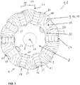
- Fig. 3
- eine schematische Querschnittsdarstellung eines Rotors einer bevorzugten Ausführungsform der permanenterregten elektrischen Maschine gemäß der Erfindung;
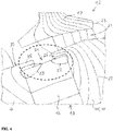
- Fig. 4
- einen Ausschnitt aus
Fig. 1 , welcher einen in einer Ausnehmung eines Rotorkörpers eines Rotors aufgenommenen Permanentmagneten sowie magnetische Flusslinien des Magnetfelds des Permanentmagneten zeigt; - Fig. 5
- ein Diagramm, in welchem ein Zusammenhang zwischen einem von der elektrischen Maschine gemäß der Erfindung erzeugten Drehmoment und einer Winkelposition des Rotors gegenüber einer elektrischen Maschine des Stands der Technik dargestellt ist;
- Die in
Fig. 3 teilweise gezeigte permanenterregte Elektromaschine 1 stellt beispielsweise einen permanenterregten Elektromotor 2 dar, welcher beispielsweise als ein bürstenloser Gleichstrommotor (BLDC) oder als ein Permanentmagnet-Synchronmotor (PMSM) ausgeführt ist. - Die Elektromaschine 1 weist eine um eine Rotationsachse 14 rotierende Welle 5 auf. Mit der Welle 5, die beispielsweise aus Stahl besteht, ist ein Nabenkörper 8 drehfest verbunden, an welchem zum einen Segmente 9 eines Rotorkörpers 10 und zum andern Permanentmagnete 15 gehalten sind. Die Segmente 9 bestehen beispielsweise aus Stahl oder beinhalten Stahl und sind in Bezug auf die Rotationsachse 14 speichenartig oder in radialer Richtung angeordnet. Vorzugsweise besteht der Rotorkörper 10 ausschließlich aus den beispielsweise separaten Segmenten 9.
- Die bevorzugt separaten Segmente 9 können insbesondere durch in axialer Richtung der Rotationsachse 14 übereinander zu einem Lamellenpaket angeordnete oder geschichtete Lamellen 16 gebildet werden. Der Rotorkörper 10 bzw. die Lamellen 16 bzw. das Lamellenpaket weisen (weist) radiale Ausnehmungen 13 auf, in denen Permanentmagnete 15 angeordnet sind. Der Nabenkörper 8 ist mit der Welle 5 zumindest drehfest verbunden und trägt den Rotorkörper 10 drehfest. Der Nabenkörper 8 kann aus einem diamagnetischen und/oder paramagnetischen Material bestehen, insbesondere aus Aluminium. Ein Rotor 4 der Elektromaschine 1 umfasst somit die Welle 5, die Permanentmagnete 15, den Rotorkörper 10, hier insbesondere als Segmente 9 aus Lamellen 16 und den Nabenkörper 8.
- Die Welle 5 ist mittels einer hier aus Maßstabsgründen nicht gezeigten Lagerung an einem hier aus Maßstabsgründen ebenfalls nicht gezeigten Gehäuse der Elektromaschine 1 gelagert. An dem Gehäuse ist ein hier abgebrochen dargestellter Stator 17 mit Elektromagneten 18 angeordnet. Zwischen dem Stator 17 und dem Rotor 4 ist ein Luftspalt 21 ausgebildet.
- An einer radial äußeren Umfangsfläche des Rotorkörpers 10 sind beispielsweise Öffnungen 24 ausgebildet, welche einerseits in die Ausnehmungen 13 und andererseits in den Luftspalt 21 münden. In den Öffnungen 24 sind insbesondere keine magnetisch leitfähigen Elemente angeordnet oder vorhanden. Die Öffnungen 24 sind daher an oder in einer radial äußeren Umfangsfläche 30 des Rotorkörpers 10 des Rotors 4 ausgebildet.
- Wie insbesondere
Fig. 4 zeigt, springt ein jeweils bevorzugt umlaufender Rand 25 der Öffnungen 24 dabei jeweils derart radial vor, dass die in den Ausnehmungen 13 aufgenommenen Permanentmagnete 15 jeweils teilweise übergriffen werden, insbesondere unter Freilassen der betreffenden Öffnung 24 durch den betreffenden Rand 25. Durch die Ränder 25 der Öffnungen 24 sind daher die Permanentmagneten 15 an ihren radial äußeren Enden in den Ausnehmungen 13 formschlüssig gehalten oder gekontert. Die radial inneren Enden der Permanentmagneten 15 können aus den Ausnehmungen 13 des Rotorkörpers 10 nach radial innen hin herausragen und den Nabenkörper 8 kontaktieren. Dann sind die Permanentmagneten 15 radial außen durch die Ränder 25 der Öffnungen 24 und radial innen durch den Nabenkörper 8 fixiert. Die Ausnehmungen 13 in dem Rotorkörper 10 können sich, wie inFig. 3 gezeigt, beispielsweise von dem Nabenkörper 8 bis zu den Öffnungen 24 im Rotorkörper 10 erstecken. Weiterhin sind die Permanentmagneten 15 und die Ausnehmungen 13 in dem Rotorkörper beispielsweise speichenartig um die Rotationsachse 14 des Rotors 4 angeordnet. - Die Segmente 9 des Rotorkörpers 10 bestehen aus wenigstens einem Metall, vorzugsweise aus Stahl und sind in Umfangsrichtung des Rotors 4 gesehen jeweils zwei benachbarten Permanentmagneten 15 zwischengeordnet. Weiterhin sind in Umfangsrichtung des Rotors 4 gesehen die Permanentmagneten 15 jeweils zwei benachbarten Segmenten zwischengeordnet.
- Wie aus
Fig. 3 hervorgeht, können die Segmente 9 an ihrer radial inneren Umfangsfläche mit dem Nabenkörper 8 verbunden sein. Insbesondere können die Segmente 9 mit dem Nabenkörper 8 formschlüssig und/oder kraftschlüssig (z.B. durch Verschraubungen oder Klemmungen) und/oder stoffschlüssig (z.B. durch Klebungen) verbunden sein. - Zur Ausbildung einer formschlüssigen Verbindung zwischen dem Nabenkörper 8 und den Segmenten 9 kann der Nabenkörper 8, wie in
Fig. 3 gezeigt, radial äußere Haken 26 aufweisen, welche mit komplementär hakenförmig geformten Aussparungen 27 an der radial inneren Umfangsfläche der Segmente 9 derart zusammenwirken, dass zwischen den Haken 26 und den Aussparungen 27 jeweils ein Formschluss mit hinterschnittenem Querschnitt ausgebildet wird. Die Haken 26 ragen insbesondere von dem Nabenkörper 8 nach radial außen weg. -
Fig. 4 zeigt magnetische Flusslinien 23 des Magnetfelds des in der dort gezeigten Ausnehmung 13 aufgenommenen Permanentmagneten 15. Daraus geht hervor, dass die magnetischen Flusslinien 23 mangels einer oben beschriebenen Brücke, welche in dem durch den gestrichelten Kreis gekennzeichneten Bereich beim Stand der Technik vorhanden ist, und aufgrund der radial äußeren Öffnung 24 im Rotorkörper 10 bzw. in der Ausnehmung 13, welche zum Luftspalt 21 hinweist, zumindest radial außen keine Verbindungen untereinander eingehen können bzw. unterbrochen werden. Dadurch wird der magnetische Streufluss verringert und damit der Wirkungsgrad des permanent erregten Elektromotors 1 verbessert. -
Fig. 5 zeigt ein Diagramm, in welchem ein Zusammenhang zwischen einem von dem permanent erregten Elektromotor 1 gemäß der Erfindung erzeugten Drehmoment M und einer Winkelposition ϕ des Rotors 4 durch eine innen offene Linie 28 dargestellt ist. Mit einer geschlossenen Linie 29 ist derselbe Zusammenhang bei einem permanent erregten Elektromotor des Stands der Technik gezeigt, welcher die eingangserwähnten Brücken 22 im Rotorkörper aufweist (Fig. 1 ,Fig. 2 ). Es kann festgestellt werden, dass das Drehmoment M des permanent erregten Elektromotors 1 gemäß der Erfindung für alle Winkelpositionen ϕ des Rotors 4 größer ist als das Drehmoment M eines Elektromotors des Stands der Technik. -
- 1
- Elektromaschine
- 2
- Elektromotor
- 3
- Generator
- 4
- Rotor
- 5
- Welle
- 6
- Auswuchtscheibe
- 7
- Aussparung
- 8
- Nabenkörper
- 9
- Segmente
- 10
- Rotorkörper
- 11
- erster Endabschnitt
- 12
- zweiter Endabschnitt
- 13
- Ausnehmungen
- 14
- Rotationsachse
- 15
- Permanentmagnete
- 16
- Lamellen
- 17
- Stator
- 18
- Elektromagneten
- 19
- Wälzlagerung
- 20
- Gehäuse
- 21
- Luftspalt
- 22
- Brücken
- 23
- magnetische Flusslinien
- 24
- Öffnungen
- 25
- Rand
- 26
- Haken
- 27
- Aussparungen
- 28
- offene Linie
- 29
- geschlossene Linie
- 30
- radial äußere Umfangsfläche
- M
- Drehmoment
- Φ
- Winkelposition Rotor
Claims (16)
- Permanenterregte Elektromaschine (1), beinhaltend einen Stator (17) und einen innerhalb des Stators (17) zusammen mit einer Welle (5) um eine Rotationsachse (14) drehbaren Rotor, wobei zwischen einer radial äußeren Umfangsfläche (30) des Rotors (4) und einer radial inneren Umfangsfläche des Stators (17) ein Luftspalt (21) ausgebildet ist, und wobei in einem Rotorkörper (10) des Rotors (4) Ausnehmungen (13) ausgebildet sind, und in wenigstens einigen der Ausnehmungen (13) Permanentmagnete (15) aufgenommen sind, dadurch gekennzeichnet, dass die Ausnehmungen (13), in welchen Permanentmagnete (15) aufgenommen sind, zum Luftspalt (21) hin offen sind.
- Permanenterregte Elektromaschine nach Anspruch 1, dadurch gekennzeichnet, dass an einer äußeren Umfangsfläche (30) des Rotorkörpers (10) Öffnungen (24) ausgebildet sind, welche einerseits in die Ausnehmungen (13) und andererseits in den Luftspalt (21) münden.
- Permanenterregte Elektromaschine nach Anspruch 2, dadurch gekennzeichnet, dass ein Rand (25) der Öffnungen (24) jeweils derart radial vorspringt, dass der die in den Ausnehmungen (13) aufgenommenen Permanentmagneten (15) jeweils teilweise übergriffen werden.
- Permanenterregte Elektromaschine nach einem der vorhergehenden Ansprüche, dadurch gekennzeichnet, dass die Permanentmagneten (15) speichenartig um die Rotationsachse (14) des Rotors (4) angeordnet sind.
- Permanenterregte Elektromaschine nach einem der vorhergehenden Ansprüche, dadurch gekennzeichnet, dass der Rotorkörper (10) Segmente (9) aus wenigstens einem Metall umfasst, welche speichenartig um die Rotationsachse (14) des Rotors (4) angeordnet und in Umfangsrichtung des Rotors gesehen den Permanentmagneten (15) zwischengeordnet sind.
- Permanenterregte Elektromaschine nach Anspruch 5, dadurch gekennzeichnet, dass die Segmente (9) separate Segmente sind.
- Permanenterregte Elektromaschine nach Anspruch 5 oder 6, dadurch gekennzeichnet, dass die Segmente (9) jeweils aus mehreren Lamellen bestehen, die in Richtung der Rotationsachse (14) gesehen zu Lamellenpaketen geschichtet sind.
- Permanenterregte Elektromaschine nach einem der Ansprüche 5 bis 7, dadurch gekennzeichnet, dass die Segmente (9) aus Stahl bestehen oder Stahl beinhalten.
- Permanenterregte Elektromaschine nach einem der Ansprüche 5 bis 8, dadurch gekennzeichnet, dass die Segmente (9) an ihrer radial inneren Umfangsfläche mit einem Nabenkörper (8) verbunden sind, welcher mit der Welle (5) zumindest drehfest verbunden ist.
- Permanenterregte Elektromaschine nach Anspruch 9, dadurch gekennzeichnet, dass die Segmente (9) mit dem Nabenkörper (8) formschlüssig und/oder kraftschlüssig und/oder stoffschlüssig verbunden sind.
- Permanenterregte Elektromaschine nach Anspruch 10, dadurch gekennzeichnet, dass der Nabenkörper (9) radial äußere Haken (26) aufweist, welche mit komplementär hakenförmig geformten Aussparungen (27) an der radial inneren Umfangsfläche der Segmente (9) derart zusammenwirken, dass zwischen den Haken (26) und den Aussparungen (27) jeweils ein Formschluss mit hinterschnittenem Querschnitt ausgebildet ist.
- Permanenterregte Elektromaschine nach einem der Ansprüche 9 bis 11, dadurch gekennzeichnet, dass der Nabenkörper (8) aus einem diamagnetischen und/oder paramagnetischen Material besteht.
- Permanenterregte Elektromaschine nach Anspruch 12, dadurch gekennzeichnet, dass der Nabenkörper (8) aus Aluminium besteht.
- Permanenterregte Elektromaschine nach einem der vorhergehenden Ansprüche, dadurch gekennzeichnet, dass sie durch einen bürstenlosen Gleichstrommotor (BLDC) gebildet wird.
- Permanenterregte Elektromaschine nach einem der vorhergehenden Ansprüche, dadurch gekennzeichnet, dass sie durch einen Permanentmagnet-Synchronmotor (PMSM) gebildet wird.
- Fahrzeug mit einer permanenterregten Elektromaschine nach wenigstens einem der vorhergehenden Ansprüche.
Applications Claiming Priority (1)
| Application Number | Priority Date | Filing Date | Title |
|---|---|---|---|
| DE102021117625.5A DE102021117625A1 (de) | 2021-07-08 | 2021-07-08 | Permanenterregte Elektromaschine |
Publications (1)
| Publication Number | Publication Date |
|---|---|
| EP4120516A1 true EP4120516A1 (de) | 2023-01-18 |
Family
ID=82308272
Family Applications (1)
| Application Number | Title | Priority Date | Filing Date |
|---|---|---|---|
| EP22180950.2A Pending EP4120516A1 (de) | 2021-07-08 | 2022-06-24 | Elektrische maschine mit permanentmagnetrotor |
Country Status (5)
| Country | Link |
|---|---|
| US (1) | US20230010022A1 (de) |
| EP (1) | EP4120516A1 (de) |
| JP (1) | JP2023010665A (de) |
| CN (1) | CN115603487A (de) |
| DE (1) | DE102021117625A1 (de) |
Families Citing this family (1)
| Publication number | Priority date | Publication date | Assignee | Title |
|---|---|---|---|---|
| DE102023123444A1 (de) * | 2023-08-31 | 2025-03-06 | Schaeffler Technologies AG & Co. KG | Rotor einer elektrischen Rotationsmaschine, Verfahren zur Herstellung des Rotors und elektrische Rotationsmaschine |
Citations (4)
| Publication number | Priority date | Publication date | Assignee | Title |
|---|---|---|---|---|
| DE102009047677A1 (de) | 2009-12-08 | 2011-06-09 | Robert Bosch Gmbh | Rotor |
| DE102010061778A1 (de) * | 2010-11-23 | 2012-05-24 | Robert Bosch Gmbh | Elektrische Maschine mit optimiertem Wirkungsgrad |
| DE102013206418A1 (de) | 2012-04-17 | 2013-10-17 | GM Global Technology Operations LLC (n.d. Ges. d. Staates Delaware) | Axial asymmetrische Permanentmagnetmaschine |
| DE102014226047A1 (de) * | 2014-12-16 | 2016-06-16 | Robert Bosch Gmbh | Speichenrotor mit Umspritzung |
Family Cites Families (18)
| Publication number | Priority date | Publication date | Assignee | Title |
|---|---|---|---|---|
| EP1249919B1 (de) | 2000-05-03 | 2006-03-15 | Moteurs Leroy-Somer | Rotor einer rotierenden elektrischen Maschine |
| FR2821024B1 (fr) | 2001-02-20 | 2003-06-13 | Leroy Somer Moteurs | Element d'entrainement tel qu'une roue motrice ou un treuil de levage, comportant un moteur synchrone |
| DE102011000439A1 (de) * | 2011-02-01 | 2012-08-02 | Uwe Guthardt | Permanentmagnetläufer für rotierende elektrische Maschinen und Verfahren zur Ausrichtung und Befestigung der Läuferpole auf einem Läufergrundkörper des Permanentmagnetläufers |
| CN102957237B (zh) * | 2011-08-22 | 2017-02-01 | 德昌电机(深圳)有限公司 | 无刷电机及其电机转子 |
| JP6018815B2 (ja) * | 2012-06-22 | 2016-11-02 | 株式会社ミツバ | ロータ、及び電動モータ |
| JP5877777B2 (ja) | 2012-09-26 | 2016-03-08 | 日立オートモティブシステムズ株式会社 | 回転電機、磁極ピース製造方法 |
| US9882440B2 (en) | 2012-10-15 | 2018-01-30 | Regal Beloit America, Inc. | Radially embedded permanent magnet rotor and methods thereof |
| GB2517410A (en) * | 2013-07-16 | 2015-02-25 | Aim Co Ltd | A Stator and a Rotor for an Electric Motor |
| US9287742B2 (en) * | 2013-08-05 | 2016-03-15 | General Electric Company | Spoke permanent magnet machine with reduced torque ripple and method of manufacturing thereof |
| DE102014001243A1 (de) | 2014-02-03 | 2015-08-06 | Baumüller Directmotion Gmbh | Elektrische Maschine |
| DE102014212872A1 (de) * | 2014-07-03 | 2016-01-07 | Schaeffler Technologies AG & Co. KG | Elektrische Maschine mit mechanischer Feldschwächung und Fail-Safe-Aktuatorik |
| JP6464822B2 (ja) * | 2015-02-27 | 2019-02-06 | 日本電産株式会社 | モータ |
| WO2017046952A1 (ja) * | 2015-09-18 | 2017-03-23 | 株式会社安川電機 | 回転電機 |
| GB2546298B (en) * | 2016-01-14 | 2022-06-15 | Advanced Electric Machines Group Ltd | Rotor assembly |
| JP6640621B2 (ja) * | 2016-03-17 | 2020-02-05 | 株式会社ミツバ | 電動機用ロータ、およびブラシレスモータ |
| EP3276794B1 (de) * | 2016-07-29 | 2018-09-19 | Etel S. A.. | Rotor für einen synchronmotor |
| DE102018130518A1 (de) * | 2018-11-30 | 2020-06-04 | Schaeffler Technologies AG & Co. KG | Permanentmagnet-Rotor für einen bürstenlosen Elektromotor und Verfahren zur Montage eines Permanentmagnet-Rotors für einen bürstenlosen Elektromotor |
| JP2021069161A (ja) * | 2019-10-18 | 2021-04-30 | パナソニックIpマネジメント株式会社 | 電動工具及びモータ |
-
2021
- 2021-07-08 DE DE102021117625.5A patent/DE102021117625A1/de active Pending
-
2022
- 2022-06-24 EP EP22180950.2A patent/EP4120516A1/de active Pending
- 2022-06-30 US US17/854,321 patent/US20230010022A1/en active Pending
- 2022-07-07 JP JP2022109535A patent/JP2023010665A/ja active Pending
- 2022-07-08 CN CN202210804829.1A patent/CN115603487A/zh active Pending
Patent Citations (4)
| Publication number | Priority date | Publication date | Assignee | Title |
|---|---|---|---|---|
| DE102009047677A1 (de) | 2009-12-08 | 2011-06-09 | Robert Bosch Gmbh | Rotor |
| DE102010061778A1 (de) * | 2010-11-23 | 2012-05-24 | Robert Bosch Gmbh | Elektrische Maschine mit optimiertem Wirkungsgrad |
| DE102013206418A1 (de) | 2012-04-17 | 2013-10-17 | GM Global Technology Operations LLC (n.d. Ges. d. Staates Delaware) | Axial asymmetrische Permanentmagnetmaschine |
| DE102014226047A1 (de) * | 2014-12-16 | 2016-06-16 | Robert Bosch Gmbh | Speichenrotor mit Umspritzung |
Also Published As
| Publication number | Publication date |
|---|---|
| CN115603487A (zh) | 2023-01-13 |
| JP2023010665A (ja) | 2023-01-20 |
| US20230010022A1 (en) | 2023-01-12 |
| DE102021117625A1 (de) | 2023-01-12 |
Similar Documents
| Publication | Publication Date | Title |
|---|---|---|
| DE69425921T2 (de) | Rotor für einen elektrischen Kompressormotor | |
| DE102004036691B4 (de) | Rotor für eine rotierende Maschine eines Reluktanztyps | |
| EP2195908B1 (de) | Elektrische maschine und rotoranordnung | |
| EP2696469B1 (de) | Rotor für eine permanent erregte Synchronmaschine | |
| EP2961039A1 (de) | Mechanisch stabilisierter Rotor für einen Reluktanzmotor | |
| EP3103183A1 (de) | Reluktanzrotor mit mechanischer stabilisierung | |
| EP2479872B1 (de) | Permanenterregte synchronmaschine mit einem rotor | |
| DE102009017850A1 (de) | Läufer für eine elektrische Maschine | |
| EP2793365A1 (de) | Einzelsegmentläufer mit durch Biegeträger gehaltenen Einzelsegmenten und Herstellungsverfahren | |
| EP3352331A1 (de) | Rotorblech für einen permanenterregten elektromotor und rotor | |
| DE102012223598A1 (de) | Rotor für eine Elektromaschine mit Aussparungen in Magnettaschen | |
| DE102019212256A1 (de) | Rotor mit minierten Streustegen | |
| DE102013200476A1 (de) | Permanenterregte Synchronmaschine mit einem Rotor mit Permanentmagneten und Verfahren zur Herstellung derartiger Maschinen bzw. Rotoren | |
| DE102009029065A1 (de) | Elektrische Maschine mit reduziertem Rastmoment, insbesondere permanentmagneterregte Synchronmaschine | |
| DE102008016890A1 (de) | Rotor mit Endscheibe für dynamoelektrische Maschine | |
| DE112017000188T5 (de) | Bürstenloser Gleichstrommotor | |
| DE102021117625A1 (de) | Permanenterregte Elektromaschine | |
| EP3610559A1 (de) | Elektrischer antriebsmotor | |
| DE102021125206A1 (de) | Elektromechanische Rotortopologie zur Steigerung der Effizienz elektrischer Maschinen | |
| DE102012218993A1 (de) | Läuferanordnung für eine permanentmagneterregte elektrische Maschine | |
| DE102012219017A1 (de) | Läuferanordnung für eine permanentmagneterregte elektrische Maschine | |
| EP3154176A1 (de) | Elektrischer antriebsmotor | |
| EP2871752B1 (de) | Läufer einer rotatorischen permanenterregten Synchronmaschine | |
| DE102023201706A1 (de) | Rotor mit Schrägung sowie Verfahren zur Herstellung des Rotors | |
| EP4445477A1 (de) | Stator für eine axialflussmaschine |
Legal Events
| Date | Code | Title | Description |
|---|---|---|---|
| PUAI | Public reference made under article 153(3) epc to a published international application that has entered the european phase |
Free format text: ORIGINAL CODE: 0009012 |
|
| STAA | Information on the status of an ep patent application or granted ep patent |
Free format text: STATUS: THE APPLICATION HAS BEEN PUBLISHED |
|
| AK | Designated contracting states |
Kind code of ref document: A1 Designated state(s): AL AT BE BG CH CY CZ DE DK EE ES FI FR GB GR HR HU IE IS IT LI LT LU LV MC MK MT NL NO PL PT RO RS SE SI SK SM TR |
|
| STAA | Information on the status of an ep patent application or granted ep patent |
Free format text: STATUS: REQUEST FOR EXAMINATION WAS MADE |
|
| 17P | Request for examination filed |
Effective date: 20230718 |
|
| RBV | Designated contracting states (corrected) |
Designated state(s): AL AT BE BG CH CY CZ DE DK EE ES FI FR GB GR HR HU IE IS IT LI LT LU LV MC MK MT NL NO PL PT RO RS SE SI SK SM TR |
|
| RAP3 | Party data changed (applicant data changed or rights of an application transferred) |
Owner name: KNORR-BREMSE SYSTEME FUER NUTZFAHRZEUGE GMBH |
|
| STAA | Information on the status of an ep patent application or granted ep patent |
Free format text: STATUS: EXAMINATION IS IN PROGRESS |
|
| 17Q | First examination report despatched |
Effective date: 20250225 |