EP4119911A1 - Einstech-speisenthermometer - Google Patents
Einstech-speisenthermometer Download PDFInfo
- Publication number
- EP4119911A1 EP4119911A1 EP21186000.2A EP21186000A EP4119911A1 EP 4119911 A1 EP4119911 A1 EP 4119911A1 EP 21186000 A EP21186000 A EP 21186000A EP 4119911 A1 EP4119911 A1 EP 4119911A1
- Authority
- EP
- European Patent Office
- Prior art keywords
- food
- probe
- energy converter
- heat conductor
- thermometer
- Prior art date
- Legal status (The legal status is an assumption and is not a legal conclusion. Google has not performed a legal analysis and makes no representation as to the accuracy of the status listed.)
- Granted
Links
Images


Classifications
-
- G—PHYSICS
- G01—MEASURING; TESTING
- G01K—MEASURING TEMPERATURE; MEASURING QUANTITY OF HEAT; THERMALLY-SENSITIVE ELEMENTS NOT OTHERWISE PROVIDED FOR
- G01K7/00—Measuring temperature based on the use of electric or magnetic elements directly sensitive to heat ; Power supply therefor, e.g. using thermoelectric elements
- G01K7/16—Measuring temperature based on the use of electric or magnetic elements directly sensitive to heat ; Power supply therefor, e.g. using thermoelectric elements using resistive elements
-
- G—PHYSICS
- G01—MEASURING; TESTING
- G01K—MEASURING TEMPERATURE; MEASURING QUANTITY OF HEAT; THERMALLY-SENSITIVE ELEMENTS NOT OTHERWISE PROVIDED FOR
- G01K1/00—Details of thermometers not specially adapted for particular types of thermometer
- G01K1/16—Special arrangements for conducting heat from the object to the sensitive element
-
- G—PHYSICS
- G01—MEASURING; TESTING
- G01K—MEASURING TEMPERATURE; MEASURING QUANTITY OF HEAT; THERMALLY-SENSITIVE ELEMENTS NOT OTHERWISE PROVIDED FOR
- G01K7/00—Measuring temperature based on the use of electric or magnetic elements directly sensitive to heat ; Power supply therefor, e.g. using thermoelectric elements
- G01K7/02—Measuring temperature based on the use of electric or magnetic elements directly sensitive to heat ; Power supply therefor, e.g. using thermoelectric elements using thermoelectric elements, e.g. thermocouples
- G01K7/04—Measuring temperature based on the use of electric or magnetic elements directly sensitive to heat ; Power supply therefor, e.g. using thermoelectric elements using thermoelectric elements, e.g. thermocouples the object to be measured not forming one of the thermoelectric materials
-
- G—PHYSICS
- G01—MEASURING; TESTING
- G01K—MEASURING TEMPERATURE; MEASURING QUANTITY OF HEAT; THERMALLY-SENSITIVE ELEMENTS NOT OTHERWISE PROVIDED FOR
- G01K1/00—Details of thermometers not specially adapted for particular types of thermometer
-
- G—PHYSICS
- G01—MEASURING; TESTING
- G01K—MEASURING TEMPERATURE; MEASURING QUANTITY OF HEAT; THERMALLY-SENSITIVE ELEMENTS NOT OTHERWISE PROVIDED FOR
- G01K1/00—Details of thermometers not specially adapted for particular types of thermometer
- G01K1/02—Means for indicating or recording specially adapted for thermometers
- G01K1/024—Means for indicating or recording specially adapted for thermometers for remote indication
-
- G—PHYSICS
- G01—MEASURING; TESTING
- G01K—MEASURING TEMPERATURE; MEASURING QUANTITY OF HEAT; THERMALLY-SENSITIVE ELEMENTS NOT OTHERWISE PROVIDED FOR
- G01K13/00—Thermometers specially adapted for specific purposes
- G01K13/10—Thermometers specially adapted for specific purposes for measuring temperature within piled or stacked materials
-
- H—ELECTRICITY
- H02—GENERATION; CONVERSION OR DISTRIBUTION OF ELECTRIC POWER
- H02N—ELECTRIC MACHINES NOT OTHERWISE PROVIDED FOR
- H02N11/00—Generators or motors not provided for elsewhere; Alleged perpetua mobilia obtained by electric or magnetic means
- H02N11/002—Generators
-
- G—PHYSICS
- G01—MEASURING; TESTING
- G01K—MEASURING TEMPERATURE; MEASURING QUANTITY OF HEAT; THERMALLY-SENSITIVE ELEMENTS NOT OTHERWISE PROVIDED FOR
- G01K2207/00—Application of thermometers in household appliances
- G01K2207/02—Application of thermometers in household appliances for measuring food temperature
- G01K2207/06—Application of thermometers in household appliances for measuring food temperature for preparation purposes
-
- H—ELECTRICITY
- H02—GENERATION; CONVERSION OR DISTRIBUTION OF ELECTRIC POWER
- H02J—ELECTRIC POWER NETWORKS; CIRCUIT ARRANGEMENTS OR SYSTEMS FOR SUPPLYING OR DISTRIBUTING ELECTRIC POWER; SYSTEMS FOR STORING ELECTRIC ENERGY
- H02J50/00—Circuit arrangements or systems for wireless supply or distribution of electric power
- H02J50/001—Energy harvesting or scavenging
Definitions
- the invention relates to an electric stick-in food thermometer.
- a meal is food that is prepared. Preparation may involve warming or heating. Examples of food that can be prepared by warming or heating are meat, vegetables, or dough for baked goods.
- a food thermometer is a temperature measuring device which is intended and suitable for measuring the temperature in food during its preparation.
- a food thermometer can therefore measure temperatures that can occur when preparing a meal. Temperatures that deviate significantly from this cannot be measured.
- a food thermometer is up to the environmental conditions that can arise during the preparation of a meal.
- temperatures of less than 200°C are reached during the preparation of a meal.
- temperatures of 350°C can also be reached, for example for baking a pizza.
- Temperatures of more than 350°C are generally not exceeded.
- a food thermometer within the meaning of the present invention is therefore set up in such a way that temperatures above 400° C., preferably above 300° C., particularly preferably above 250° C., can no longer be measured.
- the food probe is set up in such a way that it can be used in a conventional oven, i.e. at temperatures of up to 250°C.
- a food thermometer within the meaning of the present invention is not designed in such a way that very low temperatures can be measured with it, for example temperatures well below minus temperatures, such as are reached in common household chest freezers or freezers.
- a food thermometer within the meaning of the present invention is therefore not designed in such a way that it can measure temperatures below -70°C.
- a food thermometer within the meaning of the present invention is designed in such a way that it can no longer measure temperatures below -50° C., because food is usually prepared with the addition of heat and very low temperatures are only used to freeze food.
- a food probe according to the present invention can withstand a steam atmosphere.
- a food thermometer is therefore always encapsulated waterproof.
- a food thermometer within the meaning of the present invention is resistant to the usual ingredients in a meal, such as acid from lemons or vinegar.
- a food thermometer is a penetration food thermometer within the meaning of the present invention if it is intended and suitable for being inserted into food in order to be able to measure a temperature inside the food.
- a penetration food thermometer has an elongate probe with a pointed or at least a very thin end so that the probe can also be inserted into relatively solid food such as meat.
- the probe includes a sensor with which a temperature can be measured.
- a stick-in food probe has a handle that is not intended to be inserted into the food.
- the handle part can be gripped by a user in order to be able to pull the piercing food thermometer out of food or food again.
- the handle part can also include a sensor with which a temperature can be measured. The temperature outside of a food or meal can then also be measured.
- a stick-in food thermometer within the meaning of the present invention is an electric stick-in food thermometer if it requires electricity for its operation.
- An electric food penetration probe can therefore comprise a battery or can be connected to an external electric power source in order to be supplied with electric power.
- a food thermometer with the features of the first claim is used to solve the problem.
- Advantageous configurations result from the dependent claims.
- the electric stick-in food thermometer provided to solve the task comprises an elongate measuring sensor. There is a temperature sensor inside the probe.
- the probe means that part of the food probe which is intended and suitable for being inserted into a foodstuff in order to be able to measure a temperature inside the foodstuff.
- the probe is elongated when it is much longer than it is wide and deep, or the diameter is much smaller than the length of the probe.
- the sensor can be circular in cross section. However, the cross section of the sensor can be oval, square or polygonal, for example.
- the probe is basically straight for easy insertion and removal of food.
- the sensor can be cylindrical.
- the sensor can be at least 3, 4 or 5 cm long.
- the sensor can be no more than 12, 10 or 8 cm long.
- the sensor can be, for example, at most 2 cm or 1 cm wide and/or deep, or the diameter can be at most 2 cm or 1 cm, for example.
- the sensor housing has a large surface area and is generally thin-walled, it can be made of a metal that is not optimized with regard to heat-conducting properties.
- the housing of the measuring sensor can therefore consist partly or entirely of stainless steel. However, it can also consist partially or entirely of aluminum.
- a handle part of the food probe does not belong to the probe.
- a handle portion is designed and adapted to be gripped to pierce the probe into food and to withdraw the probe from the food or food made therefrom.
- a handle part therefore generally includes a cover or casing made of a thermally insulating material such as plastic.
- a temperature sensor is an electrical or electronic component that supplies an electrical signal as a measure of the temperature.
- the temperature sensor can, for example, comprise an electrical conductor whose electrical resistance, which is dependent on the temperature, is measured. The measured electrical resistance is then the measure for the temperature.
- an energy converter that converts a temperature difference into an electric current.
- a thermal conductor that is thermally conductively connected to the energy converter. If the energy converter is inside the sensor, the heat conductor leads out of the sensor. If the energy converter is outside of the sensor, the heat conductor leads into the sensor. Constructively, it is preferable that the energy converter is located in the sensor, since the sensor is designed for good heat transfer.
- a food probe is inserted into food and the food is then heated, for example in an oven, the probe remains comparatively cool compared to the temperature outside the food.
- the food probe uses this temperature difference with the help of the heat conductor and the energy converter to generate an electric current.
- the electric power generated in this way can then be used to charge a battery of the food probe and/or to supply control electronics of the food probe with electric power.
- the heat conductor preferably extends from the energy converter to a free end of the food probe to optimize power generation.
- the heat conductor preferably passes through the handle, at least through a sleeve or casing of the handle, which consists of a thermally insulating material.
- the heat conductor can then form the end of the handle part.
- This end of the handle portion is basically a blunt end.
- the heat conductor preferably runs through the entire sensor until the heat conductor has reached the corresponding end of the sensor. This end of the food probe is basically a pointed end.
- the heat conductor is preferably made of copper, since copper is a very good heat conductor.
- the temperature difference mentioned can then be used particularly well to generate an electric current.
- Silver can also be used instead of copper.
- a metal such as gold, aluminum or tungsten is less suitable but still possible.
- the heat conductor is preferably completely or at least predominantly rod-shaped in order to be able to extend to a suitable extent within the housing of the food probe.
- the heat conductor can, for example, extend from a rear third of the food probe to a front third of the food probe in order to be able to transport heat in a suitable manner for the purpose of generating electricity.
- the energy converter is then arranged in one of the two thirds.
- the length of the heat conductor is preferably at least half as long, preferably at least 2/3 as long as the length of the food probe, in order to be able to transport heat appropriately for generating electricity.
- the heat conductor preferably serves not only to conduct heat, in order to be able to keep the installation space small.
- the food probe can include a radio device and the heat conductor can be an antenna of the radio device. Measured temperatures can then be transmitted wirelessly to an external receiver by the radio device.
- the heat conductor can be an electrical conductor via which the current generated can flow to a battery and/or to an electrical consumer of the food probe.
- the heat conductor can serve as a support for other components of the food probe.
- One or more other components, such as an electrical conductor are then attached to the heat conductor. This electrical conductor can, for example, connect a temperature sensor to control electronics.
- a circuit with two different electrical conductors for generating electrical current using the Seebeck effect can be present as an energy converter.
- the Seebeck effect means the generation of a voltage in a circuit with two different conductors when there is a temperature difference at the contact points.
- the heat conductor can adjoin a contact point in order to bring it to a different temperature than the other contact point during operation.
- the energy converter is a hollow cylinder.
- different temperatures can be achieved at contact points in an improved manner.
- the efficiency of power generation can be increased in this way.
- the hollow cylinder can then directly adjoin the housing of the measuring sensor, so that the contact points adjoining it are optimally temperature-controlled. If the sensor is only approximately cylindrical, it is advantageous for the energy converter to have a corresponding shape. The energy converter is then also only approximated to the cylindrical shape.
- the heat conductor leads into the hollow cylinder in order to be able to control the temperature in an optimized manner.
- the efficiency of electric power generation can thus be improved.
- the heat conductor preferably borders on one of the two contact points in order to optimize the desired temperature control.
- the thermal conductor can then only be separated from one contact point of the energy converter by an electrical insulator.
- the heat conductor then rests directly on one side of the electrical insulator and thus makes contact with it.
- the contact point then rests directly on the other side of the electrical insulator.
- the electrical insulator can consist, for example, of a ceramic material with good thermal conductivity.
- a thermal insulator may be adjacent to the heat conductor within the probe. It is achieved by the fact that the heat conductor is not cooled during the preparation of a meal with a thermometer inserted in it. The efficiency of electric power generation can thus be further improved.
- the other contact point of the energy converter can be thermally conductively connected to the housing of the temperature sensor via another heat conductor, for example made of copper, when the energy converter is located in the measuring sensor.
- the further heat conductor can in turn be separated from the other contact point by an electrical insulator.
- the other contact point can also directly adjoin the housing of the measuring sensor in order to be temperature-controlled in a particularly suitable manner.
- An electrical insulator can then also be located between the other contact point and the housing of the measuring sensor. In turn, the efficiency for generating electrical power can be improved in this way.
- the additional heat conductor can be connected to a housing part of the handle part. The further heat conductor can thus contact the part of the housing in which the heat conductor is located in order to improve the electrical power generation.
- the energy converter can be dimensioned and arranged such that one contact point is in the area of the food probe that is kept comparatively cool during the preparation of a meal and the other contact point is in the area of the food probe that is heated to a greater extent during the preparation of a meal.
- One contact point can then be arranged in the sensor and the other Contact point outside the probe.
- the solution with one or two heat conductors is to be preferred.
- a thermal conductor can be one of the two electrical conductors of the energy converter.
- the probe can have a pointed end.
- the sensor can then be inserted into a foodstuff particularly easily.
- the food probe can include a handle part with a handle area made of plastic.
- the handle portion is used to grasp a food thermometer and pierce it into food or to pull it out of the food or food again.
- the food thermometer can be in the form of a pen. This form is particularly suitable for realizing the invention.
- the energy converter can be electrically connected to a battery of the food probe.
- the electrical current generated by the energy converter can then be used to charge the battery.
- the figure 1 shows a pen-shaped food thermometer 1, which is inserted into a bread dough 2.
- the bread dough 2 is in an oven 3 and is heated.
- the food thermometer 1 measures temperatures and transmits measured temperatures through a radio unit 4 to an external device. Bread preparation can be controlled by the external device.
- the front part of the food thermometer 1, which is to be inserted into the food 2, is the sensor 5 of the food thermometer 1.
- Within the sensor 5 there is at least one temperature sensor.
- the probe 5 includes a tip 6.
- the probe 5 may be limited to a front third or a front half of the food probe 1.
- the rear part of the food thermometer 1 comprises a casing made of a heat-insulating plastic material such as rubber or elastomer and serving as a handle 7 .
- the rear end of the food thermometer 1 is formed by a heat conductor 8 .
- the heat conductor 8 extends inside the housing 9 in the direction of the sensor 5.
- the heat conductor 8 can be made of copper, for example.
- the housing 9 can be made of stainless steel or aluminum, for example.
- thermometer 1 is intended and suitable for being pierced into a food 2 . It is therefore a penetration food thermometer.
- the rear end of the food thermometer 1 can also include one or more temperature sensors in order to also be able to measure the ambient temperature during the preparation of a meal.
- the figure 2 shows a section through an electrical piercing food thermometer 1, which in the figure 1 shown electric piercing food thermometer 1 is similar.
- An energy converter 10 is located inside the housing 9, specifically in the front third.
- the energy converter 10 is constructed like a Peltier element.
- the essentially rod-shaped heat conductor 8 makes contact with the energy converter 10 in such a way that it is adjacent to an electrical contact point of the energy converter 10 .
- Another heat conductor 11 adjoins the other electrical contact point of the energy converter 10 .
- the other heat conductor 11 is also connected to the case 9 .
- the other heat conductor 11 can also be made of copper.
- a temperature sensor 12 is located at the tip 6.
- a temperature sensor 13 is located at the rear end of the food probe 1.
- the two temperature sensors 12 and 13 are electrically connected to control electronics 14 of the food probe 1.
- the energy converter 10 is electrically connected to a battery 15 which is located between the temperature sensor 12 and the control electronics 14 .
- the control electronics 14 include a wireless radio unit.
- the control electronics 14 can be electrically connected to the Heat conductor 8 be connected.
- the essentially rod-shaped heat conductor 8 then serves as an antenna for the radio unit of the control electronics 14.
- the control electronics 14 can be arranged between the energy converter 10 and the battery 15, for example.
- the probe 5 of the food probe 1 is to be inserted into food. Once this is done and the food 2 is in a heated oven 3, the rear end 8 of the food probe 1 is heated. The heat is transported to the first electrical contact point of the energy converter 10 via the essentially rod-shaped heat conductor 8 .
- the sensor 5 is thermally shielded by the food 2 .
- the part of the housing 9 that belongs to the sensor 5 is therefore initially hardly heated and remains relatively cool.
- the second electrical contact point of the energy converter 10 is therefore kept cool via the other heat conductor 11 .
- the energy converter 10 then generates electrical current with which the battery 15 can be charged.
- the temperature inside food can be measured by the temperature sensor 12 .
- the ambient temperature can be measured by the temperature sensor 13 during the preparation of a meal.
- An electrical conductor can be attached to the rod-shaped heat conductor 8, which connects the temperature sensor 13 to the control electronics 14 at the rear end of the stick-in food thermometer.
- the heat conductor 8 can therefore also be used to suitably fix one or more electrical lines
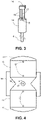
- a hollow-cylindrical energy converter 10 with a substantially rod-shaped heat conductor 8 for a stick-in food thermometer is shown.
- the rod-shaped heat conductor 8 leads into the hollow-cylindrical energy converter 10 in order to supply heat to an electrical contact point of the energy converter 10 .
- Electrical connections 16 connect the energy converter 10 to the control electronics 14 in order to supply the control electronics 14 with power.
- An electrical conductor 17 is also connected to the control electronics 14 and the thermal conductor 8 .
- the thermal conductor 8 can now, for example, in turn serve as an antenna for a radio unit of the control electronics 14 .
- the hollow cylinder shape enables a significantly larger area to be used to generate electricity.
- the hollow cylindrical shape can directly contact the housing of the food probe 1 in the area of the temperature sensor over a large area. It higher efficiencies are possible compared to the previously described embodiments.
- FIG 4 a plan view of energy converters 10 arranged one above the other for a stick-in food thermometer is shown, which are separated from one another by a heat-conducting layer 18 .
- a rod-shaped heat conductor 8 leads into the heat-conducting layer 18 .
- the thermally conductive layer 18 can be made of copper. However, other materials with good thermal conductivity are also possible.
- Thermally insulating layers 19 laterally adjoin the thermally conductive layer 18 and partially the energy converter 10 . The thermally insulating layers 19 prevent the regions of the energy converters 10 that are to be kept cool from heating up.
- the thermally insulating layers 19 can extend into the heat-conducting layer 18 in the manner of a bulge or tip, for example, in order to improve thermal insulation.
- Thermally conductive layers 11 adjoin the respective energy converter 10 on the upper side and on the underside. The surface of each may be arcuate to provide good contact with the adjacent housing of the penetration food probe.
- the one in the figure 4 shown energy converter 10 can be cuboid. For example, further energy converters can be arranged in pairs in front of and/or behind.
- the energy converter 10 includes two outer ceramic layers 20, which are good thermal conductors.
- the two ceramic layers 20 can be thermally separated from one another on the outer sides by a heat-insulating, sufficiently temperature-stable material 21 .
- Within the energy converter 10 there are alternating conductors A and B made of metal, for example.
- the material of the conductor A differs from the material of the conductor B.
- Only the ends of the electrical conductors A and B are electrically connected in pairs and offset as shown. This creates two different contact points 23 and 24.
- One contact point 23 borders on the one outer ceramic layer 20.
- the other contact point 24 borders on the other outer ceramic layer 20. If the two different ceramic layers 20 are heated differently, an electric electricity generated.
- Electrical conductors 16 lead out of the energy converter 10 and can, for example, contact a battery in order to be able to charge it.
- the ceramic layers 20 can be planar.
- the energy converter 10 can then be cuboid.
- the layers 20 can also be the outer and inner shell of a hollow cylinder.
- the energy converter 10 can then be in the form of a hollow cylinder.
Landscapes
- Physics & Mathematics (AREA)
- General Physics & Mathematics (AREA)
- Measuring Temperature Or Quantity Of Heat (AREA)
Abstract
Description
- Die Erfindung betrifft ein elektrisches Einstech-Speisenthermometer.
- Eine Speise ist eine Nahrung, die zubereitet wird. Die Zubereitung kann das Erwärmen oder Erhitzen umfassen. Beispiele für eine Nahrung, die durch Erwärmen oder Erhitzen zubereitet werden kann, sind Fleisch, Gemüse oder Teig für Backwaren.
- Ein Speisenthermometer ist ein Temperaturmessgerät, welches dafür bestimmt und geeignet ist, Temperaturen in einem Nahrungsmittel während seiner Zubereitung zu messen. Ein Speisenthermometer kann daher Temperaturen messen, die bei der Zubereitung einer Speise auftreten können. Deutlich davon abweichende Temperaturen können nicht gemessen werden. Außerdem ist ein Speisenthermometer den Umgebungsbedingungen gewachsen, die während einer Zubereitung einer Speise auftreten können.
- In der Regel werden bei der Zubereitung einer Speise Temperaturen von weniger als 200°C erreicht. Es können aber auch Temperaturen von 350°C erreicht werden, so zum Beispiel für das Backen einer Pizza. Temperaturen von mehr als 350°C werden grundsätzlich nicht überschritten. Ein Speisenthermometer im Sinne der vorliegenden Erfindung ist daher so eingerichtet, dass Temperaturen oberhalb von 400°C, vorzugsweise oberhalb von 300°C, besonders bevorzugt oberhalb von 250°C, nicht mehr gemessen werden können. Grundsätzlich ist das Speisenthermometer so eingerichtet, dass dieses in einem herkömmlichen Backofen eingesetzt werden kann, also bei Temperaturen von bis zu 250°C.
- Ein Speisenthermometer im Sinne der vorliegenden Erfindung ist nicht so ausgelegt, dass sehr tiefe Temperaturen damit gemessen werden können wie zum Beispiel Temperaturen deutlich unterhalb von Minustemperaturen, wie diese in haushaltsüblichen Gefriertruhen oder Gefrierschränken erreicht werden. Ein Speisenthermometer im Sinne der vorliegenden Erfindung ist daher nicht so ausgelegt, dass es Temperaturen von weniger als -70°C messen kann. Grundsätzlich ist ein Speisenthermometer im Sinne der vorliegenden Erfindung so ausgelegt, dass es Temperaturen unterhalb von -50°C nicht mehr messen kann, weil Speisen in der Regel unter Zufuhr von Wärme hergestellt werden und sehr tiefe Temperaturen lediglich für ein Einfrieren einer Speise angewendet werden.
- Ein Speisenthermometer im Sinne der vorliegenden Erfindung kann einer Dampfatmosphäre widerstehen. Ein Speisenthermometer ist daher grundsätzlich wasserdicht gekapselt. Ein Speisenthermometer im Sinne der vorliegenden Erfindung ist resistent gegenüber üblichen Zutaten einer Speise wie zum Beispiel Säure von Zitronen oder Essig.
- Ein Speisenthermometer ist ein Einstech-Speisenthermometer im Sinne der vorliegenden Erfindung, wenn es dafür bestimmt und geeignet ist, in eine Nahrung hineingestochen zu werden, um eine Temperatur im Inneren der Nahrung messen zu können. Ein Einstech-Speisenthermometer weist einen langgestreckten Messfühler mit einem spitzen oder zumindest einem sehr dünnen Ende auf, um den Messfühler auch in relativ feste Nahrung wie Fleisch hineinstechen zu können. Der Messfühler umfasst einen Sensor, mit dem eine Temperatur gemessen werden kann. Ein Einstech-Speisenthermometer weist ein Griffteil auf, das nicht dafür bestimmt ist, in die Speise hineingesteckt zu werden. Das Griffteil kann von einem Benutzer ergriffen werden, um das Einstech-Speisenthermometer aus einer Nahrung bzw. Speise wieder herausziehen zu können. Das Griffteil kann ebenfalls einen Sensor umfassen, mit dem eine Temperatur gemessen werden kann. Es kann dann auch die Temperatur außerhalb einer Nahrung bzw. Speise gemessen werden.
- Ein Einstech-Speisenthermometer im Sinne der vorliegenden Erfindung ist ein elektrisches Einstech-Speisenthermometer, wenn es für seinen Betrieb elektrischen Strom benötigt. Ein elektrisches Einstech-Speisenthermometer kann daher eine Batterie umfassen oder aber an eine externe elektrische Energiequelle angeschlossen werden, um mit elektrischem Strom versorgt zu werden.
- Es ist Aufgabe der vorliegenden Erfindung, die Temperatur in einer Speise während der Zubereitung unabhängig von einer externen Stromversorgung messen zu können.
- Zur Lösung der Aufgabe dient ein Speisenthermometer mit den Merkmalen des ersten Anspruchs. Vorteilhafte Ausgestaltungen ergeben sich aus den abhängigen Ansprüchen.
- Das zur Lösung der Aufgabe bereitgestellte elektrische Einstech-Speisenthermometer umfasst einen langgestreckten Messfühler. Es gibt einen Temperatursensor innerhalb des Messfühlers. Mit Messfühler ist der Teil des Speisenthermometers gemeint, der dazu bestimmt und geeignet ist, in ein Nahrungsmittel hineingestochen zu werden, um im Inneren des Nahrungsmittels eine Temperatur messen zu können.
- Der Messfühler ist langgestreckt, wenn dieser sehr viel länger als breit und tief ist bzw. der Durchmesser sehr viel kleiner als die Länge des Messfühlers ist. Im Querschnitt kann der Messfühler kreisrund sein. Der Messfühler kann aber im Querschnitt beispielsweise oval, quadratisch oder mehreckig sein. Der Messfühler verläuft grundsätzlich geradlinig, um leicht in ein Nahrungsmittel hineingesteckt und leicht wieder herausgezogen werden zu können. Der Messfühler kann zylinderförmig sein. Der Messfühler kann beispielsweise wenigstens 3, 4 oder 5 cm lang sein. Der Messfühler kann beispielsweise nicht mehr als 12, 10 oder 8 cm lang sein. Der Messfühler kann beispielsweise maximal 2 cm oder 1 cm breit und/oder tief sein bzw. der Durchmesser kann beispielsweise maximal 2 cm oder 1 cm betragen. Da das Gehäuse des Messfühlers eine große Oberfläche aufweist und grundsätzlich dünnwandig ist, kann dieses aus einem Metall bestehen, dass nicht in Bezug auf wärmeleitende Eigenschaften optimiert ist. Das Gehäuse des Messfühlers kann daher teilweise oder vollständig aus Edelstahl bestehen. Es kann aber auch teilweise oder vollständig aus Aluminium bestehen.
- Nicht zum Messfühler gehört ein Griffteil des Speisenthermometers. Ein Griffteil ist dazu bestimmt und geeignet, ergriffen zu werden, um den Messfühler in ein Nahrungsmittel hineinzustechen und den Messfühler aus dem Nahrungsmittel bzw. der daraus hergestellten Speise wieder herauszuziehen. Ein Griffteil umfasst daher in der Regel eine Hülle oder Ummantelung aus einem thermisch isolierenden Material wie Kunststoff.
- Damit eine Temperatur im Inneren eines Nahrungsmittels bzw. einer Speise gemessen werden kann, gibt es zumindest einen Temperatursensor innerhalb des Messfühlers. Ein Temperatursensor ist ein elektrisches oder elektronisches Bauelement, das ein elektrisches Signal als Maß für die Temperatur liefert. Der Temperatursensor kann beispielsweise einen elektrischen Leiter umfassen, dessen von der Temperatur abhängiger elektrischer Widerstand gemessen wird. Der gemessene elektrische Widerstand ist dann das Maß für die Temperatur.
- Es gibt einen Energiewandler, der eine Temperaturdifferenz in einen elektrischen Strom umwandelt. Es gibt einen Wärmeleiter, der mit dem Energiewandler wärmeleitend verbunden ist. Befindet sich der Energiewandler innerhalb des Messfühlers, so führt der Wärmeleiter aus dem Messfühler heraus. Befindet sich der Energiewandler außerhalb des Messfühlers, so führt der Wärmeleiter in den Messfühler hinein. Konstruktiv ist zu bevorzugen, dass sich der Energiewandler im Messfühler befindet, da der Messfühler auf eine gute Wärmeübertragung ausgelegt ist.
- Wird ein Speisenthermometer in ein Nahrungsmittel hineingestochen und wird das Nahrungsmittel dann beispielsweise in einem Backofen erhitzt, so bleibt der Messfühler vergleichsweise kühl im Vergleich zur Temperatur außerhalb des Nahrungsmittels. Diese Temperaturdifferenz nützt das Speisenthermometer mithilfe des Wärmeleiters und des Energiewandlers aus, um einen elektrischen Strom zu erzeugen. Der so erzeugte elektrische Strom kann dann dazu genutzt werden, um eine Batterie des Speisenthermometers zu laden und/oder eine Steuerelektronik des Speisenthermometers mit elektrischem Strom zu versorgen.
- Der Wärmeleiter erstreckt sich vorzugsweise von dem Energiewandler bis zu einem freien Ende des Speisenthermometers, um die Stromerzeugung zu optimieren. Ist der Messfühler beispielsweise mit einem Griffteil unmittelbar verbunden und befindet sich der Energiewandler im Messfühler, dann führt der Wärmeleiter vorzugsweise durch das Griffteil hindurch und zwar wenigstens durch eine Hülle oder Ummantelung des Griffteils, die aus einem thermisch isolierenden Material besteht. Der Wärmeleiter kann dann das Ende des Griffteils bilden. Dieses Ende des Griffteils ist grundsätzlich ein stumpfes Ende. Ist der Messfühler beispielsweise mit einem Griffteil unmittelbar verbunden und befindet sich der Energiewandler im Griffteil, dann führt der Wärmeleiter vorzugsweise durch den gesamten Messfühler hindurch, bis der Wärmeleiter das entsprechende Ende des Messfühlers erreicht hat. Dieses Ende des Speisenthermometers ist grundsätzlich ein spitzes Ende.
- Der Wärmeleiter besteht vorzugsweise aus Kupfer, da Kupfer ein sehr guter Wärmeleiter ist. Es kann dann die genannte Temperaturdifferenz besonders gut zur Erzeugung eines elektrischen Stroms ausgenutzt werden. Anstelle von Kupfer kommt auch Silber in Betracht. Weniger geeignet aber immer noch möglich ist ein Metall wie Gold, Aluminium oder Wolfram.
- Der Wärmeleiter ist vorzugsweise vollständig oder zumindest überwiegend stabförmig, um sich innerhalb des Gehäuses des Speisenthermometers geeignet weit erstrecken zu können. Der Wärmeleiter kann sich beispielsweise von einem hinteren Drittel des Speisenthermometers bis zu einem vorderen Drittel des Speisenthermometers erstrecken, um Wärme zwecks Stromerzeugung geeignet transportieren zu können. Der Energiewandler ist dann in einem der beiden Drittel angeordnet.
- Die Länge des Wärmeleiters ist vorzugsweise wenigstens halb so lang, vorzugsweise wenigsten 2/3 so lang wie die Länge des Speisenthermometers, um geeignet Wärme für eine Stromerzeugung transportieren zu können.
- Vorzugsweise dient der Wärmeleiter nicht nur der Leitung von Wärme, um den Bauraum klein halten zu können. So kann das Speisenthermometer eine Funkeinrichtung umfassen und der Wärmeleiter eine Antenne der Funkeinrichtung sein. Durch die Funkeinrichtung können dann gemessene Temperaturen drahtlos an ein externes Empfangsgerät übermittelt werden. Der Wärmeleiter kann ein elektrischer Leiter sein, über den erzeugter Strom zu einer Batterie und/oder zu einem elektrischen Verbraucher des Speisenthermometers fließen kann. Der Wärmeleiter kann als Halterung für andere Komponenten des Speisenthermometers dienen. An dem Wärmeleiter sind dann ein oder mehrere andere Komponenten wie zum Beispiel ein elektrischer Leiter befestigt. Dieser elektrische Leiter kann beispielsweise einen Temperatursensor mit einer Steuerelektronik verbinden.
- Als Energiewandler kann ein Stromkreis mit zwei verschiedenen elektrischen Leitern für die Erzeugung von elektrischem Strom mittels Seebeck-Effekt vorhanden sein. Mit Seebeck-Effekt ist die Entstehung einer Spannung in einem Stromkreis mit zwei unterschiedlichen Leitern bei einer Temperaturdifferenz an den Kontaktstellen gemeint. Der Wärmeleiter kann an eine Kontaktstelle angrenzen, um diese während des Betriebs auf eine andere Temperatur zu bringen als die andere Kontaktstelle.
- In einer bevorzugten Ausgestaltung ist der Energiewandler ein Hohlzylinder. Dadurch können verbessert unterschiedliche Temperaturen an Kontaktstellen erreicht werden. Der Wirkungsgrad für die Stromerzeugung kann so gesteigert werden. Dies gilt insbesondere dann, wenn auch der Messfühler zylinderförmig ist. Dann kann der Hohlzylinder unmittelbar an das Gehäuse des Messfühlers angrenzen, damit daran angrenzende Kontaktstellen in optimaler Weise temperiert werden. Weist der Messfühler nur näherungsweise eine Zylinderform auf, so ist es von Vorteil, dass auch der Energiewandler eine entsprechende Form aufweist. Der Energiewandler ist dann also der Zylinderform ebenfalls lediglich angenähert.
- In einer bevorzugten Ausgestaltung führt der Wärmeleiter in den Hohlzylinder hinein, um in optimierter Weise temperieren zu können. Der Wirkungsgrad der elektrischen Stromerzeugung kann so verbessert werden.
- Der Wärmeleiter grenzt vorzugsweise an eine der beiden Kontaktstellen an, um die gewünschte Temperierung zu optimieren. Der Wärmeleiter kann dann lediglich durch einen elektrischen Isolator von der einen Kontaktstelle des Energiewandlers getrennt sein. An der einen Seite des elektrischen Isolators liegt dann der Wärmeleiter unmittelbar an und kontaktiert diesen also. An der anderen Seite des elektrischen Isolators liegt dann die Kontaktstelle unmittelbar an.
- Der elektrische Isolator kann beispielsweise aus einem gut wärmeleitenden keramischen Material bestehen.
- An den Wärmeleiter kann innerhalb des Messfühlers ein thermischer Isolator angrenzen. Es wird dadurch erreicht, dass der Wärmeleiter während der Zubereitung einer Speise mit darin eingestecktem Thermometer nicht gekühlt wird. Der Wirkungsgrad der elektrischen Stromerzeugung kann so weiter verbessert werden.
- Die andere Kontaktstelle des Energiewandlers kann über einen weiteren, beispielsweise aus Kupfer bestehenden Wärmeleiter mit dem Gehäuse des Temperaturfühlers wärmeleitend verbunden sein, wenn sich der Energiewandler im Messfühler befindet. Der weitere Wärmeleiter kann wiederum durch einen elektrischen Isolator von der anderen Kontaktstelle getrennt sein. Die andere Kontaktstelle kann aber auch unmittelbar an das Gehäuse des Messfühlers angrenzen, um besonders geeignet temperiert zu werden. Zwischen der anderen Kontaktstelle und dem Gehäuse des Messfühlers kann sich dann noch ein elektrischer Isolator befinden. Wiederum kann so der Wirkungsgrad zur Erzeugung von elektrischem Strom verbessert werden. Befindet sich der Energiewandler im Griffteil, so kann der weitere Wärmeleiter mit einem Gehäuseteil des Griffteils verbunden sein. Der weitere Wärmeleiter kann also den Teil des Gehäuses kontaktieren, in dem sich der Wärmeleiter befindet, um die elektrische Stromerzeugung zu verbessern.
- Das Vorsehen von ein oder zwei Wärmeleitern ist nicht zwingend erforderlich, um erfindungsgemäß Strom zu erzeugen. Der Energiewandler kann alternativ so dimensioniert und angeordnet sein, dass eine Kontaktstelle in dem Bereich des Speisenthermometers liegt, der während der Zubereitung einer Speise vergleichsweise kühl gehalten wird und die andere Kontaktstelle in dem Bereich des Speisenthermometers, die während der Zubereitung einer Speise stärker erhitzt wird. Die eine Kontaktstelle kann also dann im Messfühler angeordnet sein und die andere Kontaktstelle außerhalb des Messfühlers. Aus Fertigungsgründen ist die Lösung mit den ein oder zwei Wärmeleitern jedoch zu bevorzugen.
- Ein Wärmeleiter kann einer der beiden elektrischen Leiter des Energiewandlers sein.
- Der Messfühler kann ein spitzes Ende aufweisen. Der Messfühler kann dann besonders leicht in ein Nahrungsmittel hineingestochen werden.
- Das Speisenthermometer kann ein Griffteil mit einem aus Kunststoff bestehenden Griffbereich umfassen. Das Griffteil dient dazu, ein Speisenthermometer zu ergreifen und in ein Nahrungsmittel hineinzustechen oder es aus dem Nahrungsmittel bzw. der Speise wieder herauszuziehen.
- Das Speisenthermometer kann stiftförmig sein. Diese Form ist zur Realisierung der Erfindung besonders geeignet.
- Der Energiewandler kann mit einer Batterie des Speisenthermometers elektrisch verbunden sein. Der durch den Energiewandler erzeugte elektrische Strom kann dann für ein Aufladen der Batterie genutzt werden.
- Nachfolgend wird die Erfindung anhand von Beispielen näher erläutert.
- Es zeigen
- Figur 1:
- stiftförmiges elektrisches Einstech-Speisenthermometer während einer Speisenzubereitung;
- Figur 2:
- Schnitt durch ein elektrisches Einstech-Speisenthermometer;
- Figur 3:
- Ausführungsform eines Energiewandlers für ein elektrisches EinstechSpeisenthermometer;
- Figur 4:
- Ausführungsform eines Energiewandlers für ein elektrisches EinstechSpeisenthermometer;
- Figur 5:
- Schnitt durch einen Energiewandler.
- Die
Figur 1 zeigt ein stiftförmiges Speisenthermometer 1, welches in einen Brotteig 2 hineingesteckt ist. Der Brotteig 2 befindet sich in einem Backofen 3 und wird erhitzt. Das Speisenthermometer 1 misst Temperaturen und übermittelt gemessene Temperaturen durch eine Funkeinheit 4 an ein externes Gerät. Durch das externe Gerät kann die Brotzubereitung gesteuert werden. Der vordere Teil des Speisenthermometers 1, der in das Nahrungsmittel 2 hineingesteckt werden soll, ist der Messfühler 5 des Speisenthermometers 1. Innerhalb des Messfühlers 5 befindet sich zumindest ein Temperatursensor. Damit der Messfühler 5 leicht in ein Nahrungsmittel 2 hineingesteckt werden kann, umfasst der Messfühler 5 eine Spitze 6. Der Messfühler 5 kann auf ein vorderes Drittel oder eine vordere Hälfte des Speisenthermometers 1 beschränkt sein. Der hintere Teil des Speisenthermometers 1 umfasst eine als Griff 7 dienende Ummantelung aus einem wärmeisolierenden Kunststoffmaterial wie Gummi oder Elastomer. Das hintere Ende des Speisenthermometers 1 wird durch einen Wärmeleiter 8 gebildet. Der Wärmeleiter 8 erstreckt sich innerhalb des Gehäuses 9 in Richtung Messfühler 5. Der Wärmeleiter 8 kann beispielsweise aus Kupfer bestehen. Das Gehäuse 9 kann beispielsweise aus Edelstahl oder aus Aluminium bestehen. - Das Thermometer 1 ist dazu bestimmt und geeignet, in ein Nahrungsmittel 2 hineingestochen zu werden. Es ist folglich ein Einstech-Speisenthermometer.
- Auch das hintere Ende des Speisenthermometers 1 kann ein oder mehrere Temperatursensoren umfassen, um auch die Umgebungstemperatur während der Zubereitung einer Speise messen zu können.
- Die
Figur 2 zeigt einen Schnitt durch ein elektrisches Einstech-Speisenthermometer 1, welches dem in derFigur 1 gezeigten elektrischen Einstech-Speisenthermometer 1 ähnelt. Innerhalb des Gehäuses 9 und zwar im vorderen Drittel befindet sich ein Energiewandler 10. Der Energiewandler 10 ist wie ein Peltierelement aufgebaut. Der im Wesentlichen stabförmige Wärmeleiter 8 kontaktiert den Energiewandler 10 und zwar derart, dass dieser an eine elektrische Kontaktstelle des Energiewandlers 10 angrenzt. An die andere elektrische Kontaktstelle des Energiewandlers 10 grenzt ein anderer Wärmeleiter 11 an. Der andere Wärmeleiter 11 ist außerdem mit dem Gehäuse 9 verbunden. Auch der andere Wärmeleiter 11 kann aus Kupfer bestehen. Bei der Spitze 6 befindet sich ein Temperatursensor 12. Ein Temperatursensor 13 befindet sich beim hinteren Ende des Speisenthermometers 1. Die beiden Temperatursensoren 12 und 13 sind elektrisch mit einer Steuerelektronik 14 des Speisenthermometers 1 verbunden. Der Energiewandler 10 ist elektrisch mit einer Batterie 15 verbunden, die sich zwischen dem Temperatursensor 12 und der Steuerelektronik 14 befindet. Die Steuerelektronik 14 umfasst eine drahtlose Funkeinheit. Die Steuerelektronik 14 kann elektrisch mit dem Wärmeleiter 8 verbunden sein. Der im Wesentlichen stabförmige Wärmeleiter 8 dient dann als Antenne für die Funkeinheit der Steuerelektronik 14. Die Steuerelektronik 14 kann beispielsweise zwischen dem Energiewandler 10 und der Batterie 15 angeordnet sein. - Der Messfühler 5 des Speisenthermometers 1 soll in eine Nahrung hineingestochen werden. Ist dies geschehen und befindet sich die Nahrung 2 in einem erhitzten Ofen 3, so wird das hintere Ende 8 des Speisenthermometers 1 erhitzt. Über den im Wesentlichen stabförmigen Wärmeleiter 8 wird die Hitze zu der einen ersten elektrischen Kontaktstelle des Energiewandlers 10 transportiert.
- Der Messfühler 5 wird durch die Nahrung 2 thermisch abgeschirmt. Der Teil des Gehäuses 9, der zum Messfühler 5 gehört, wird daher zunächst kaum erhitzt und bleibt verhältnismäßig kühl. Über den anderen Wärmeleiter 11 wird daher die zweite elektrische Kontaktstelle des Energiewandlers 10 kühl gehalten. Der Energiewandler 10 erzeugt dann elektrischen Strom, mit dem die Batterie 15 aufgeladen werden kann.
- Durch den Temperatursensor 12 kann die Temperatur im Inneren einer Nahrung gemessen werden. Durch den Temperatursensor 13 kann die Umgebungstemperatur während der Zubereitung einer Speise gemessen werden.
- An dem stabförmigen Wärmeleiter 8 kann ein elektrischer Leiter angebracht sein, der den Temperatursensor 13 beim hinteren Ende des Einstech-Speisenthermometers mit der Steuerelektronik 14 verbindet. Der Wärmeleiter 8 kann also auch dazu genutzt werden, um ein oder mehrere elektrische Leitungen geeignet zu fixieren
- In der
Figur 3 wird ein hohlzylinderförmiger Energiewandler 10 mit einem im Wesentlichen stabförmigen Wärmeleiter 8 für ein Einstech-Speisenthermometer gezeigt. Der stabförmige Wärmeleiter 8 führt in den hohlzylinderförmigen Energiewandler 10 hinein, um einer elektrischen Kontaktstelle des Energiewandlers 10 Wärme zuzuführen. Elektrische Anschlüsse 16 verbinden den Energiewandler 10 mit der Steuerelektronik 14, um die Steuerelektronik 14 mit Strom zu versorgen. Ein elektrischer Leiter 17 ist ebenfalls mit der Steuerelektronik 14 sowie dem Wärmeleiter 8 verbunden. Der Wärmeleiter 8 kann nun beispielsweise wiederum als Antenne für eine Funkeinheit der Steuerelektronik 14 dienen. Die Hohlzylinderform ermöglicht die Nutzung einer deutlich größeren Fläche zur Stromgewinnung. Außerdem kann die Hohlzylinderform unmittelbar großflächig das Gehäuse des Speisenthermometers 1 im Bereich des Temperaturfühlers kontaktieren. Es sind so höhere Wirkungsgrade im Vergleich zu der zuvor beschriebenen Ausführungsformen möglich. - In der
Figur 4 wird eine Aufsicht auf übereinander angeordnete Energiewandler 10 für ein Einstech-Speisenthermometer gezeigt, die durch eine wärmeleitende Schicht 18 voneinander getrennt sind. In die wärmeleitende Schicht 18 führt ein stabförmiger Wärmeleiter 8 hinein. Die wärmeleitende Schicht 18 kann wie der stabförmige Wärmeleiter 8 aus Kupfer bestehen. Andere gut wärmeleitende Materialien sind aber ebenfalls möglich. Seitlich grenzen an die wärmeleitende Schicht 18 und teilweise an den Energiewandler 10 thermisch isolierende Schichten 19 an. Durch die thermisch isolierenden Schichten 19 wird vermieden, dass sich die Bereiche der Energiewandler 10 aufheizen, die kühl gehalten werden sollen. Die thermisch isolierenden Schichten 19 können beispielsweise in der Art einer Wölbung oder Spitze in die wärmeleitende Schicht 18 hineinreichen, um verbessert thermisch zu isolieren. Wärmeleitende Schichten 11 grenzen an der Oberseite und an der Unterseite an den jeweiligen Energiewandler 10 an. Die Oberfläche kann jeweils bogenförmig verlaufen, um einen guten Kontakt zum angrenzenden Gehäuse des Einstech-Speisenthermometers herzustellen. Die in derFigur 4 gezeigten Energiewandler 10 können quaderförmig sein. Es können zum Beispiel paarweise weitere Energiewandler davor und/oder dahinter angeordnet sein. - In der
Figur 5 wird im Schnitt ein Energiewandler 10 gezeigt. Der Energiewandler 10 umfasst zwei äußere keramische Schichten 20, die gut wärmeleitend sind. Die beiden keramischen Schichten 20 können von einem wärmeisolierenden, hinreichend temperaturstabilen Material 21 an den Außenseiten voneinander thermisch getrennt sein. Innerhalb des Energiewandlers 10 gibt es abwechselnd zum Beispiel aus Metall bestehende Leiter A und B. Das Material des Leiters A unterscheidet sich vom Material des Leiters B. Nur die Enden der elektrischen Leiter A und B sind paarweise sowie wie gezeigt versetzt elektrisch miteinander verbunden. Es entstehen so zwei verschiedene Kontaktstellen 23 und 24. Die eine Kontaktstelle 23 grenzt an die eine äußere keramische Schicht 20. Die andere Kontaktstelle 24 grenzt an die andere äußere keramische Schicht 20. Werden die zwei verschiedenen keramischen Schichten 20 unterschiedlich temperiert, so wird ein elektrischer Strom erzeugt. Elektrische Leiter 16 führen aus dem Energiewandler 10 heraus und können beispielsweise eine Batterie kontaktieren, um diese aufladen zu können. - Die keramischen Schichten 20 können eben sein. Der Energiewandler 10 kann dann quaderförmig sein. Die Schichten 20 können aber auch die Außen- und Innenhülle eines Hohlzylinders sein. Der Energiewandler 10 kann dann hohlzylinderförmig sein.
Claims (15)
- Elektrisches Einstech-Speisenthermometer (1) mit einem langgestreckten Messfühler (5), mit einem Temperatursensor (12) innerhalb des Messfühlers (5), mit einem Energiewandler (10), der aus einer Temperaturdifferenz einen elektrischen Strom erzeugen kann, mit einem Wärmeleiter (8), der mit dem Energiewandler (10) wärmeleitend verbunden ist, wobei der Wärmeleiter (8) aus dem Messfühler (5) herausführt, wenn der Energiewandler (10) innerhalb des Messfühlers (5) angeordnet ist und der Wärmeleiter (8) in den Messfühler (5) hineinführt, wenn der Energiewandler (10) innerhalb des Messfühlers (5) angeordnet ist.
- Speisenthermometer (1) nach einem der vorhergehenden Ansprüche, dadurch gekennzeichnet, dass der Wärmeleiter (8) aus Kupfer besteht.
- Speisenthermometer (1) nach einem der vorhergehenden Ansprüche, dadurch gekennzeichnet, dass der Wärmeleiter (8) vollständig oder zumindest überwiegend stabförmig ist.
- Speisenthermometer (1) nach einem der vorhergehenden Ansprüche, dadurch gekennzeichnet, dass sich der Wärmeleiter (8) von einem hinteren Drittel des Speisenthermometers (1) bis zu einem vorderen Drittel des Speisenthermometers (1) erstreckt und der Energiewandler (10) in einem der beiden Drittel angeordnet ist.
- Speisenthermometer (1) nach einem der vorhergehenden Ansprüche, dadurch gekennzeichnet, dass das Speisenthermometer (1) eine Funkeinrichtung umfasst und der Wärmeleiter (8) eine Antenne der Funkeinrichtung oder ein elektrischer Leiter ist, der mit einer Elektronik des Speisenthermometers (1) oder mit einer Batterie des Speisenthermometers (1) verbunden ist.
- Speisenthermometer (1) nach einem der vorhergehenden Ansprüche, dadurch gekennzeichnet, dass der Energiewandler (10) zwei verschiedene elektrische Leiter (A, B) mit zwei Kontaktstellen (23, 24) für die Erzeugung von elektrischem Strom mittels Seebeck-Effekt umfasst.
- Speisenthermometer (1) nach dem vorhergehenden Anspruch, dadurch gekennzeichnet, dass der Energiewandler (10) hohlzylinderförmig ist.
- Speisenthermometer (1) nach einem der zwei vorhergehenden Ansprüche, dadurch gekennzeichnet, dass der Wärmeleiter (8) in die Hohlzylinderform hineingeführt ist.
- Speisenthermometer (1) nach einem der drei vorhergehenden Ansprüche, dadurch gekennzeichnet, dass der Wärmeleiter (8) an eine der beiden Kontaktstellen (23, 24) angrenzt.
- Speisenthermometer (1) nach dem vorhergehenden Anspruch, dadurch gekennzeichnet, dass an den Wärmeleiter (8) innerhalb des Messfühlers (5) ein thermischer Isolator (19) grenzt.
- Speisenthermometer (1) nach einem der zwei vorhergehenden Ansprüche, dadurch gekennzeichnet, dass die andere Kontaktstelle (23, 24) über einen weiteren, aus Kupfer bestehenden Wärmeleiter (11) mit dem Gehäuse (9) des Speisenthermometers (1) wärmeleitend verbunden ist oder unmittelbar an das Gehäuse (9) des Speisenthermometers (1) angrenzt.
- Speisenthermometer (1) nach einem der vorhergehenden Ansprüche, dadurch gekennzeichnet, dass der Messfühler (5) ein spitzes Ende aufweist.
- Speisenthermometer (1) nach einem der vorhergehenden Ansprüche, dadurch gekennzeichnet, dass das Speisenthermometer (1) ein Griffteil mit einem aus Kunststoff bestehenden Griffbereich (7) umfasst.
- Speisenthermometer (1) nach einem der vorhergehenden Ansprüche, dadurch gekennzeichnet, dass das Speisenthermometer (1) stiftförmig ist.
- Speisenthermometer (1) nach einem der vorhergehenden Ansprüche, dadurch gekennzeichnet, dass der Energiewandler (10) mit einer Batterie des Speisenthermometers (1) elektrisch verbunden ist.
Priority Applications (6)
| Application Number | Priority Date | Filing Date | Title |
|---|---|---|---|
| PL21186000.2T PL4119911T3 (pl) | 2021-07-16 | 2021-07-16 | Wkłuwany termometr do potraw |
| EP21186000.2A EP4119911B1 (de) | 2021-07-16 | 2021-07-16 | Einstech-speisenthermometer |
| ES21186000T ES2982602T3 (es) | 2021-07-16 | 2021-07-16 | Termómetro de pincho para comida |
| AU2022203389A AU2022203389B2 (en) | 2021-07-16 | 2022-05-19 | Penetration food thermometer |
| US17/852,691 US20230015838A1 (en) | 2021-07-16 | 2022-06-29 | Penetration food thermometer |
| CN202210834040.0A CN115615571A (zh) | 2021-07-16 | 2022-07-14 | 刺入式食物温度计 |
Applications Claiming Priority (1)
| Application Number | Priority Date | Filing Date | Title |
|---|---|---|---|
| EP21186000.2A EP4119911B1 (de) | 2021-07-16 | 2021-07-16 | Einstech-speisenthermometer |
Publications (3)
| Publication Number | Publication Date |
|---|---|
| EP4119911A1 true EP4119911A1 (de) | 2023-01-18 |
| EP4119911C0 EP4119911C0 (de) | 2024-05-29 |
| EP4119911B1 EP4119911B1 (de) | 2024-05-29 |
Family
ID=76958753
Family Applications (1)
| Application Number | Title | Priority Date | Filing Date |
|---|---|---|---|
| EP21186000.2A Active EP4119911B1 (de) | 2021-07-16 | 2021-07-16 | Einstech-speisenthermometer |
Country Status (6)
| Country | Link |
|---|---|
| US (1) | US20230015838A1 (de) |
| EP (1) | EP4119911B1 (de) |
| CN (1) | CN115615571A (de) |
| AU (1) | AU2022203389B2 (de) |
| ES (1) | ES2982602T3 (de) |
| PL (1) | PL4119911T3 (de) |
Families Citing this family (10)
| Publication number | Priority date | Publication date | Assignee | Title |
|---|---|---|---|---|
| USD1046640S1 (en) * | 2023-03-14 | 2024-10-15 | Shenzhen Hongkang International Electronic Technology Co., Ltd. | Food thermometer |
| USD1078501S1 (en) * | 2023-03-14 | 2025-06-10 | Shenzhen Hongkang International Electronic Technology Co., Ltd. | Food thermometer set |
| USD1046638S1 (en) * | 2023-03-14 | 2024-10-15 | Shenzhen Hongkang International Electronic Technology Co., Ltd. | Food thermometer |
| USD1046637S1 (en) * | 2023-03-14 | 2024-10-15 | Shenzhen Hongkang International Electronic Technology Co., Ltd. | Food thermometer |
| USD1046639S1 (en) * | 2023-07-13 | 2024-10-15 | Shenzhen Hongkang International Electronic Technology Co., Ltd. | Food thermometer |
| USD1056738S1 (en) * | 2023-08-23 | 2025-01-07 | Shenzhen Hongkang International Electronic Technology Co., Ltd. | Food thermometer set |
| USD1070613S1 (en) * | 2023-09-28 | 2025-04-15 | Shenzhen Yingboweiye Technology Co., Ltd. | Thermometer |
| USD1101580S1 (en) | 2024-01-31 | 2025-11-11 | Sharkninja Operating Llc | Temperature probe holder |
| USD1046642S1 (en) * | 2024-03-27 | 2024-10-15 | Finemold Technologies Co., Ltd | Meat thermometer |
| USD1046643S1 (en) * | 2024-03-27 | 2024-10-15 | Yaobing Deng | Meat thermometer |
Citations (4)
| Publication number | Priority date | Publication date | Assignee | Title |
|---|---|---|---|---|
| EP1624724A1 (de) * | 2004-07-23 | 2006-02-08 | ANGELO PO GRANDI CUCINE S.p.A. | System und Sonde zur Detektion zumindest eines Parameters |
| DE102007018245A1 (de) * | 2007-03-30 | 2008-10-02 | E.G.O. Elektro-Gerätebau GmbH | Temperatursonde für einen Ofen, Ofen und Verfahren zum Betrieb eines Ofens |
| DE102010020778A1 (de) * | 2010-05-19 | 2011-11-24 | Abb Technology Ag | Autonomer Temperaturtransmitter |
| US20180353003A1 (en) * | 2017-06-08 | 2018-12-13 | Ashok Sabata | Novel Sensor Probe to Monitor Temperature during Cooking |
Family Cites Families (6)
| Publication number | Priority date | Publication date | Assignee | Title |
|---|---|---|---|---|
| DE102004047756B4 (de) * | 2004-09-30 | 2012-03-01 | BSH Bosch und Siemens Hausgeräte GmbH | Temperatursensorvorrichtung |
| CN101352307B (zh) * | 2008-09-16 | 2010-10-27 | 明高五金制品(深圳)有限公司 | 半导体制冷片温差发电电子测温锅 |
| ES2804535T3 (es) * | 2015-06-25 | 2021-02-08 | Apption Labs Ltd | Termómetro para alimentos |
| US11579019B2 (en) * | 2019-08-15 | 2023-02-14 | Te Connectivity Solutions Gmbh | Wireless energy-harvesting sensor probe |
| EP3855146B1 (de) * | 2020-01-21 | 2024-11-06 | Vorwerk & Co. Interholding GmbH | Versorgungseinheit zum erzeugen elektrischer energie, küchenutensil sowie küchensystem |
| CN114977888A (zh) * | 2021-04-23 | 2022-08-30 | 深圳市安服优智能互联科技有限公司 | 温差发电结构及测温传感器 |
-
2021
- 2021-07-16 PL PL21186000.2T patent/PL4119911T3/pl unknown
- 2021-07-16 ES ES21186000T patent/ES2982602T3/es active Active
- 2021-07-16 EP EP21186000.2A patent/EP4119911B1/de active Active
-
2022
- 2022-05-19 AU AU2022203389A patent/AU2022203389B2/en active Active
- 2022-06-29 US US17/852,691 patent/US20230015838A1/en not_active Abandoned
- 2022-07-14 CN CN202210834040.0A patent/CN115615571A/zh active Pending
Patent Citations (4)
| Publication number | Priority date | Publication date | Assignee | Title |
|---|---|---|---|---|
| EP1624724A1 (de) * | 2004-07-23 | 2006-02-08 | ANGELO PO GRANDI CUCINE S.p.A. | System und Sonde zur Detektion zumindest eines Parameters |
| DE102007018245A1 (de) * | 2007-03-30 | 2008-10-02 | E.G.O. Elektro-Gerätebau GmbH | Temperatursonde für einen Ofen, Ofen und Verfahren zum Betrieb eines Ofens |
| DE102010020778A1 (de) * | 2010-05-19 | 2011-11-24 | Abb Technology Ag | Autonomer Temperaturtransmitter |
| US20180353003A1 (en) * | 2017-06-08 | 2018-12-13 | Ashok Sabata | Novel Sensor Probe to Monitor Temperature during Cooking |
Also Published As
| Publication number | Publication date |
|---|---|
| US20230015838A1 (en) | 2023-01-19 |
| AU2022203389A1 (en) | 2023-02-02 |
| EP4119911C0 (de) | 2024-05-29 |
| PL4119911T3 (pl) | 2024-09-23 |
| CN115615571A (zh) | 2023-01-17 |
| ES2982602T3 (es) | 2024-10-17 |
| AU2022203389B2 (en) | 2026-07-16 |
| EP4119911B1 (de) | 2024-05-29 |
Similar Documents
| Publication | Publication Date | Title |
|---|---|---|
| EP4119911B1 (de) | Einstech-speisenthermometer | |
| EP3501353B1 (de) | Zubereitungsgefäss für eine küchenmaschine | |
| DE102015012683B3 (de) | Temperaturmesssonde | |
| EP3335280B1 (de) | Verbinder für supraleitfähige leiter und verwendung des verbinders | |
| DE3300677C2 (de) | Applikator zum Zuführen und/oder Abführen von Hochfrequenzenergie | |
| EP2295869A2 (de) | Garraumvorrichtung mit Dickschichtheizelement | |
| DE102016125678A1 (de) | Heizelement für eine Küchenmaschine, Küchenmaschine, Kochgefäß sowie Verfahren zur Herstellung eines Heizelementes | |
| EP4212839B1 (de) | Batteriebetriebenes speisenthermometer und herstellungsverfahren | |
| DE1059939B (de) | Elektrothermisches System | |
| DE3539402A1 (de) | Leistungsmesssensor zum messen von hochfrequenzleistung | |
| DE102014106006A1 (de) | Heizelement mit Abschnitten verschiedener Heizleistungen sowie Gargerät | |
| DE102017130234A1 (de) | Bodenteil für eine Küchenmaschine | |
| DE102017114987B3 (de) | Messsonde und Gargerät mit einer solchen Messsonde | |
| DE102011086912B4 (de) | Gargeschirrvorrichtung und Systeme mit einer solchen Gargeschirrvorrichtung | |
| DE202010006471U1 (de) | Fernsteuerbare Steckdose | |
| DE102018119012A1 (de) | Verfahren zum Garen von Lebensmitteln | |
| EP1612006A1 (de) | Beheizbares Messer | |
| DE69903542T2 (de) | Temperaturfühler und haushaltelektrogerät mit einem solchen fühler | |
| DE20108963U1 (de) | Elektrischer Flachheizkörper | |
| DE395645C (de) | Elektrisch beheiztes Buegeleisen | |
| DE4000152A1 (de) | Elektronisches thermorelais und hierfuer geeignetes thermisches element | |
| DE520168C (de) | Elektrisch geheizter Behaelter | |
| DE202008003259U1 (de) | PTC-Element | |
| DE840410C (de) | Verfahren zur Herstellung hochbeanspruchbarer Heissleiter | |
| Bresch | Development of textured multilayer thermoelectric generators based on calcium cobaltite |
Legal Events
| Date | Code | Title | Description |
|---|---|---|---|
| PUAI | Public reference made under article 153(3) epc to a published international application that has entered the european phase |
Free format text: ORIGINAL CODE: 0009012 |
|
| STAA | Information on the status of an ep patent application or granted ep patent |
Free format text: STATUS: THE APPLICATION HAS BEEN PUBLISHED |
|
| AK | Designated contracting states |
Kind code of ref document: A1 Designated state(s): AL AT BE BG CH CY CZ DE DK EE ES FI FR GB GR HR HU IE IS IT LI LT LU LV MC MK MT NL NO PL PT RO RS SE SI SK SM TR |
|
| STAA | Information on the status of an ep patent application or granted ep patent |
Free format text: STATUS: REQUEST FOR EXAMINATION WAS MADE |
|
| 17P | Request for examination filed |
Effective date: 20230309 |
|
| RBV | Designated contracting states (corrected) |
Designated state(s): AL AT BE BG CH CY CZ DE DK EE ES FI FR GB GR HR HU IE IS IT LI LT LU LV MC MK MT NL NO PL PT RO RS SE SI SK SM TR |
|
| REG | Reference to a national code |
Ref country code: DE Ref legal event code: R079 Free format text: PREVIOUS MAIN CLASS: G01K0001160000 Ipc: G01K0001024000 Ref country code: DE Ref legal event code: R079 Ref document number: 502021003838 Country of ref document: DE Free format text: PREVIOUS MAIN CLASS: G01K0001160000 Ipc: G01K0001024000 |
|
| RIC1 | Information provided on ipc code assigned before grant |
Ipc: G01K 1/16 20060101ALI20231206BHEP Ipc: G01K 1/024 20210101AFI20231206BHEP |
|
| GRAP | Despatch of communication of intention to grant a patent |
Free format text: ORIGINAL CODE: EPIDOSNIGR1 |
|
| STAA | Information on the status of an ep patent application or granted ep patent |
Free format text: STATUS: GRANT OF PATENT IS INTENDED |
|
| INTG | Intention to grant announced |
Effective date: 20240125 |
|
| GRAS | Grant fee paid |
Free format text: ORIGINAL CODE: EPIDOSNIGR3 |
|
| GRAA | (expected) grant |
Free format text: ORIGINAL CODE: 0009210 |
|
| STAA | Information on the status of an ep patent application or granted ep patent |
Free format text: STATUS: THE PATENT HAS BEEN GRANTED |
|
| AK | Designated contracting states |
Kind code of ref document: B1 Designated state(s): AL AT BE BG CH CY CZ DE DK EE ES FI FR GB GR HR HU IE IS IT LI LT LU LV MC MK MT NL NO PL PT RO RS SE SI SK SM TR |
|
| REG | Reference to a national code |
Ref country code: CH Ref legal event code: EP |
|
| REG | Reference to a national code |
Ref country code: IE Ref legal event code: FG4D Free format text: LANGUAGE OF EP DOCUMENT: GERMAN |
|
| REG | Reference to a national code |
Ref country code: DE Ref legal event code: R096 Ref document number: 502021003838 Country of ref document: DE |
|
| U01 | Request for unitary effect filed |
Effective date: 20240529 |
|
| U07 | Unitary effect registered |
Designated state(s): AT BE BG DE DK EE FI FR IT LT LU LV MT NL PT SE SI Effective date: 20240604 |
|
| U20 | Renewal fee for the european patent with unitary effect paid |
Year of fee payment: 4 Effective date: 20240822 |
|
| PG25 | Lapsed in a contracting state [announced via postgrant information from national office to epo] |
Ref country code: IS Free format text: LAPSE BECAUSE OF FAILURE TO SUBMIT A TRANSLATION OF THE DESCRIPTION OR TO PAY THE FEE WITHIN THE PRESCRIBED TIME-LIMIT Effective date: 20240929 |
|
| PG25 | Lapsed in a contracting state [announced via postgrant information from national office to epo] |
Ref country code: HR Free format text: LAPSE BECAUSE OF FAILURE TO SUBMIT A TRANSLATION OF THE DESCRIPTION OR TO PAY THE FEE WITHIN THE PRESCRIBED TIME-LIMIT Effective date: 20240529 |
|
| PG25 | Lapsed in a contracting state [announced via postgrant information from national office to epo] |
Ref country code: GR Free format text: LAPSE BECAUSE OF FAILURE TO SUBMIT A TRANSLATION OF THE DESCRIPTION OR TO PAY THE FEE WITHIN THE PRESCRIBED TIME-LIMIT Effective date: 20240830 |
|
| REG | Reference to a national code |
Ref country code: ES Ref legal event code: FG2A Ref document number: 2982602 Country of ref document: ES Kind code of ref document: T3 Effective date: 20241017 |
|
| PG25 | Lapsed in a contracting state [announced via postgrant information from national office to epo] |
Ref country code: NO Free format text: LAPSE BECAUSE OF FAILURE TO SUBMIT A TRANSLATION OF THE DESCRIPTION OR TO PAY THE FEE WITHIN THE PRESCRIBED TIME-LIMIT Effective date: 20240829 Ref country code: IS Free format text: LAPSE BECAUSE OF FAILURE TO SUBMIT A TRANSLATION OF THE DESCRIPTION OR TO PAY THE FEE WITHIN THE PRESCRIBED TIME-LIMIT Effective date: 20240929 Ref country code: HR Free format text: LAPSE BECAUSE OF FAILURE TO SUBMIT A TRANSLATION OF THE DESCRIPTION OR TO PAY THE FEE WITHIN THE PRESCRIBED TIME-LIMIT Effective date: 20240529 Ref country code: GR Free format text: LAPSE BECAUSE OF FAILURE TO SUBMIT A TRANSLATION OF THE DESCRIPTION OR TO PAY THE FEE WITHIN THE PRESCRIBED TIME-LIMIT Effective date: 20240830 Ref country code: RS Free format text: LAPSE BECAUSE OF FAILURE TO SUBMIT A TRANSLATION OF THE DESCRIPTION OR TO PAY THE FEE WITHIN THE PRESCRIBED TIME-LIMIT Effective date: 20240829 |
|
| PG25 | Lapsed in a contracting state [announced via postgrant information from national office to epo] |
Ref country code: CZ Free format text: LAPSE BECAUSE OF FAILURE TO SUBMIT A TRANSLATION OF THE DESCRIPTION OR TO PAY THE FEE WITHIN THE PRESCRIBED TIME-LIMIT Effective date: 20240529 |
|
| PG25 | Lapsed in a contracting state [announced via postgrant information from national office to epo] |
Ref country code: SK Free format text: LAPSE BECAUSE OF FAILURE TO SUBMIT A TRANSLATION OF THE DESCRIPTION OR TO PAY THE FEE WITHIN THE PRESCRIBED TIME-LIMIT Effective date: 20240529 Ref country code: RO Free format text: LAPSE BECAUSE OF FAILURE TO SUBMIT A TRANSLATION OF THE DESCRIPTION OR TO PAY THE FEE WITHIN THE PRESCRIBED TIME-LIMIT Effective date: 20240529 |
|
| PG25 | Lapsed in a contracting state [announced via postgrant information from national office to epo] |
Ref country code: SM Free format text: LAPSE BECAUSE OF FAILURE TO SUBMIT A TRANSLATION OF THE DESCRIPTION OR TO PAY THE FEE WITHIN THE PRESCRIBED TIME-LIMIT Effective date: 20240529 |
|
| PG25 | Lapsed in a contracting state [announced via postgrant information from national office to epo] |
Ref country code: SM Free format text: LAPSE BECAUSE OF FAILURE TO SUBMIT A TRANSLATION OF THE DESCRIPTION OR TO PAY THE FEE WITHIN THE PRESCRIBED TIME-LIMIT Effective date: 20240529 Ref country code: SK Free format text: LAPSE BECAUSE OF FAILURE TO SUBMIT A TRANSLATION OF THE DESCRIPTION OR TO PAY THE FEE WITHIN THE PRESCRIBED TIME-LIMIT Effective date: 20240529 Ref country code: RO Free format text: LAPSE BECAUSE OF FAILURE TO SUBMIT A TRANSLATION OF THE DESCRIPTION OR TO PAY THE FEE WITHIN THE PRESCRIBED TIME-LIMIT Effective date: 20240529 Ref country code: CZ Free format text: LAPSE BECAUSE OF FAILURE TO SUBMIT A TRANSLATION OF THE DESCRIPTION OR TO PAY THE FEE WITHIN THE PRESCRIBED TIME-LIMIT Effective date: 20240529 |
|
| PG25 | Lapsed in a contracting state [announced via postgrant information from national office to epo] |
Ref country code: MC Free format text: LAPSE BECAUSE OF FAILURE TO SUBMIT A TRANSLATION OF THE DESCRIPTION OR TO PAY THE FEE WITHIN THE PRESCRIBED TIME-LIMIT Effective date: 20240529 |
|
| PLBE | No opposition filed within time limit |
Free format text: ORIGINAL CODE: 0009261 |
|
| STAA | Information on the status of an ep patent application or granted ep patent |
Free format text: STATUS: NO OPPOSITION FILED WITHIN TIME LIMIT |
|
| 26N | No opposition filed |
Effective date: 20250303 |
|
| PG25 | Lapsed in a contracting state [announced via postgrant information from national office to epo] |
Ref country code: IE Free format text: LAPSE BECAUSE OF NON-PAYMENT OF DUE FEES Effective date: 20240716 |
|
| U20 | Renewal fee for the european patent with unitary effect paid |
Year of fee payment: 5 Effective date: 20250729 |
|
| PGFP | Annual fee paid to national office [announced via postgrant information from national office to epo] |
Ref country code: ES Payment date: 20250819 Year of fee payment: 5 |
|
| PGFP | Annual fee paid to national office [announced via postgrant information from national office to epo] |
Ref country code: PL Payment date: 20250704 Year of fee payment: 5 |
|
| PGFP | Annual fee paid to national office [announced via postgrant information from national office to epo] |
Ref country code: GB Payment date: 20250724 Year of fee payment: 5 |
|
| PGFP | Annual fee paid to national office [announced via postgrant information from national office to epo] |
Ref country code: CH Payment date: 20250801 Year of fee payment: 5 |
|
| PG25 | Lapsed in a contracting state [announced via postgrant information from national office to epo] |
Ref country code: CY Free format text: LAPSE BECAUSE OF FAILURE TO SUBMIT A TRANSLATION OF THE DESCRIPTION OR TO PAY THE FEE WITHIN THE PRESCRIBED TIME-LIMIT; INVALID AB INITIO Effective date: 20210716 |
|
| PG25 | Lapsed in a contracting state [announced via postgrant information from national office to epo] |
Ref country code: HU Free format text: LAPSE BECAUSE OF FAILURE TO SUBMIT A TRANSLATION OF THE DESCRIPTION OR TO PAY THE FEE WITHIN THE PRESCRIBED TIME-LIMIT; INVALID AB INITIO Effective date: 20210716 |
|
| PG25 | Lapsed in a contracting state [announced via postgrant information from national office to epo] |
Ref country code: TR Free format text: LAPSE BECAUSE OF FAILURE TO SUBMIT A TRANSLATION OF THE DESCRIPTION OR TO PAY THE FEE WITHIN THE PRESCRIBED TIME-LIMIT Effective date: 20240529 |
|
| REG | Reference to a national code |
Ref country code: CH Ref legal event code: U11 Free format text: ST27 STATUS EVENT CODE: U-0-0-U10-U11 (AS PROVIDED BY THE NATIONAL OFFICE) Effective date: 20260801 |