EP4116639A1 - Vorkühlkreis und verfahren zur helium-kälteversorgung - Google Patents
Vorkühlkreis und verfahren zur helium-kälteversorgung Download PDFInfo
- Publication number
- EP4116639A1 EP4116639A1 EP21020348.5A EP21020348A EP4116639A1 EP 4116639 A1 EP4116639 A1 EP 4116639A1 EP 21020348 A EP21020348 A EP 21020348A EP 4116639 A1 EP4116639 A1 EP 4116639A1
- Authority
- EP
- European Patent Office
- Prior art keywords
- helium
- cooling
- cooling bath
- return line
- cold
- Prior art date
- Legal status (The legal status is an assumption and is not a legal conclusion. Google has not performed a legal analysis and makes no representation as to the accuracy of the status listed.)
- Withdrawn
Links
Images

Classifications
-
- F—MECHANICAL ENGINEERING; LIGHTING; HEATING; WEAPONS; BLASTING
- F25—REFRIGERATION OR COOLING; COMBINED HEATING AND REFRIGERATION SYSTEMS; HEAT PUMP SYSTEMS; MANUFACTURE OR STORAGE OF ICE; LIQUEFACTION SOLIDIFICATION OF GASES
- F25B—REFRIGERATION MACHINES, PLANTS OR SYSTEMS; COMBINED HEATING AND REFRIGERATION SYSTEMS; HEAT PUMP SYSTEMS
- F25B9/00—Compression machines, plants or systems, in which the refrigerant is air or other gas of low boiling point
- F25B9/14—Compression machines, plants or systems, in which the refrigerant is air or other gas of low boiling point characterised by the cycle used, e.g. Stirling cycle
-
- F—MECHANICAL ENGINEERING; LIGHTING; HEATING; WEAPONS; BLASTING
- F25—REFRIGERATION OR COOLING; COMBINED HEATING AND REFRIGERATION SYSTEMS; HEAT PUMP SYSTEMS; MANUFACTURE OR STORAGE OF ICE; LIQUEFACTION SOLIDIFICATION OF GASES
- F25B—REFRIGERATION MACHINES, PLANTS OR SYSTEMS; COMBINED HEATING AND REFRIGERATION SYSTEMS; HEAT PUMP SYSTEMS
- F25B1/00—Compression machines, plants or systems with non-reversible cycle
- F25B1/10—Compression machines, plants or systems with non-reversible cycle with multi-stage compression
-
- F—MECHANICAL ENGINEERING; LIGHTING; HEATING; WEAPONS; BLASTING
- F25—REFRIGERATION OR COOLING; COMBINED HEATING AND REFRIGERATION SYSTEMS; HEAT PUMP SYSTEMS; MANUFACTURE OR STORAGE OF ICE; LIQUEFACTION SOLIDIFICATION OF GASES
- F25B—REFRIGERATION MACHINES, PLANTS OR SYSTEMS; COMBINED HEATING AND REFRIGERATION SYSTEMS; HEAT PUMP SYSTEMS
- F25B40/00—Subcoolers, desuperheaters or superheaters
-
- F—MECHANICAL ENGINEERING; LIGHTING; HEATING; WEAPONS; BLASTING
- F25—REFRIGERATION OR COOLING; COMBINED HEATING AND REFRIGERATION SYSTEMS; HEAT PUMP SYSTEMS; MANUFACTURE OR STORAGE OF ICE; LIQUEFACTION SOLIDIFICATION OF GASES
- F25B—REFRIGERATION MACHINES, PLANTS OR SYSTEMS; COMBINED HEATING AND REFRIGERATION SYSTEMS; HEAT PUMP SYSTEMS
- F25B41/00—Fluid-circulation arrangements
- F25B41/20—Disposition of valves, e.g. of on-off valves or flow control valves
-
- F—MECHANICAL ENGINEERING; LIGHTING; HEATING; WEAPONS; BLASTING
- F25—REFRIGERATION OR COOLING; COMBINED HEATING AND REFRIGERATION SYSTEMS; HEAT PUMP SYSTEMS; MANUFACTURE OR STORAGE OF ICE; LIQUEFACTION SOLIDIFICATION OF GASES
- F25B—REFRIGERATION MACHINES, PLANTS OR SYSTEMS; COMBINED HEATING AND REFRIGERATION SYSTEMS; HEAT PUMP SYSTEMS
- F25B41/00—Fluid-circulation arrangements
- F25B41/20—Disposition of valves, e.g. of on-off valves or flow control valves
- F25B41/24—Arrangement of shut-off valves for disconnecting a part of the refrigerant cycle, e.g. an outdoor part
-
- F—MECHANICAL ENGINEERING; LIGHTING; HEATING; WEAPONS; BLASTING
- F25—REFRIGERATION OR COOLING; COMBINED HEATING AND REFRIGERATION SYSTEMS; HEAT PUMP SYSTEMS; MANUFACTURE OR STORAGE OF ICE; LIQUEFACTION SOLIDIFICATION OF GASES
- F25B—REFRIGERATION MACHINES, PLANTS OR SYSTEMS; COMBINED HEATING AND REFRIGERATION SYSTEMS; HEAT PUMP SYSTEMS
- F25B5/00—Compression machines, plants or systems, with several evaporator circuits, e.g. for varying refrigerating capacity
- F25B5/02—Compression machines, plants or systems, with several evaporator circuits, e.g. for varying refrigerating capacity arranged in parallel
-
- F—MECHANICAL ENGINEERING; LIGHTING; HEATING; WEAPONS; BLASTING
- F25—REFRIGERATION OR COOLING; COMBINED HEATING AND REFRIGERATION SYSTEMS; HEAT PUMP SYSTEMS; MANUFACTURE OR STORAGE OF ICE; LIQUEFACTION SOLIDIFICATION OF GASES
- F25B—REFRIGERATION MACHINES, PLANTS OR SYSTEMS; COMBINED HEATING AND REFRIGERATION SYSTEMS; HEAT PUMP SYSTEMS
- F25B9/00—Compression machines, plants or systems, in which the refrigerant is air or other gas of low boiling point
- F25B9/002—Compression machines, plants or systems, in which the refrigerant is air or other gas of low boiling point characterised by the refrigerant
-
- F—MECHANICAL ENGINEERING; LIGHTING; HEATING; WEAPONS; BLASTING
- F25—REFRIGERATION OR COOLING; COMBINED HEATING AND REFRIGERATION SYSTEMS; HEAT PUMP SYSTEMS; MANUFACTURE OR STORAGE OF ICE; LIQUEFACTION SOLIDIFICATION OF GASES
- F25B—REFRIGERATION MACHINES, PLANTS OR SYSTEMS; COMBINED HEATING AND REFRIGERATION SYSTEMS; HEAT PUMP SYSTEMS
- F25B9/00—Compression machines, plants or systems, in which the refrigerant is air or other gas of low boiling point
- F25B9/08—Compression machines, plants or systems, in which the refrigerant is air or other gas of low boiling point using ejectors
-
- H—ELECTRICITY
- H05—ELECTRIC TECHNIQUES NOT OTHERWISE PROVIDED FOR
- H05K—PRINTED CIRCUITS; CASINGS OR CONSTRUCTIONAL DETAILS OF ELECTRIC APPARATUS; MANUFACTURE OF ASSEMBLAGES OF ELECTRICAL COMPONENTS
- H05K7/00—Constructional details common to different types of electric apparatus
- H05K7/20—Modifications to facilitate cooling, ventilating, or heating
- H05K7/2029—Modifications to facilitate cooling, ventilating, or heating using a liquid coolant with phase change in electronic enclosures
- H05K7/20354—Refrigerating circuit comprising a compressor
-
- F—MECHANICAL ENGINEERING; LIGHTING; HEATING; WEAPONS; BLASTING
- F25—REFRIGERATION OR COOLING; COMBINED HEATING AND REFRIGERATION SYSTEMS; HEAT PUMP SYSTEMS; MANUFACTURE OR STORAGE OF ICE; LIQUEFACTION SOLIDIFICATION OF GASES
- F25B—REFRIGERATION MACHINES, PLANTS OR SYSTEMS; COMBINED HEATING AND REFRIGERATION SYSTEMS; HEAT PUMP SYSTEMS
- F25B2341/00—Details of ejectors not being used as compression device; Details of flow restrictors or expansion valves
- F25B2341/001—Ejectors not being used as compression device
- F25B2341/0011—Ejectors with the cooled primary flow at reduced or low pressure
-
- F—MECHANICAL ENGINEERING; LIGHTING; HEATING; WEAPONS; BLASTING
- F25—REFRIGERATION OR COOLING; COMBINED HEATING AND REFRIGERATION SYSTEMS; HEAT PUMP SYSTEMS; MANUFACTURE OR STORAGE OF ICE; LIQUEFACTION SOLIDIFICATION OF GASES
- F25B—REFRIGERATION MACHINES, PLANTS OR SYSTEMS; COMBINED HEATING AND REFRIGERATION SYSTEMS; HEAT PUMP SYSTEMS
- F25B2400/00—Component parts or details not otherwise provided for in this subclass
- F25B2400/07—Details of compressors or related parts
- F25B2400/075—Details of compressors or related parts with parallel compressors
-
- F—MECHANICAL ENGINEERING; LIGHTING; HEATING; WEAPONS; BLASTING
- F25—REFRIGERATION OR COOLING; COMBINED HEATING AND REFRIGERATION SYSTEMS; HEAT PUMP SYSTEMS; MANUFACTURE OR STORAGE OF ICE; LIQUEFACTION SOLIDIFICATION OF GASES
- F25B—REFRIGERATION MACHINES, PLANTS OR SYSTEMS; COMBINED HEATING AND REFRIGERATION SYSTEMS; HEAT PUMP SYSTEMS
- F25B2400/00—Component parts or details not otherwise provided for in this subclass
- F25B2400/23—Separators
Definitions
- the invention relates to a pre-cooling circuit and a method for supplying helium to cool at least one consumer to be cooled.
- Cooling temperatures well below 1 K are required in basic research and for cooling quantum computers.
- state-of-the-art mixing cryostats are used, which are pre-cooled to the range of 3 - 4 K with pulsation tube, Sterling or Gifford-McMahon coolers.
- a low pre-cooling temperature is a prerequisite for the efficiency of the mixing cryostat.
- the cooling capacity of these pre-cooling machines is in the range of just a few watts with additional cooling capacity of 50 K as shield cooling. For this reason, mixing cryostats are each equipped with 2 pulsation tube coolers, for example.
- the (closed) pre-cooling circuit for supplying helium cold to at least one consumer to be cooled comprises a supply line and a return line which are connected to one another via a cold emission device, the cold emission device being set up to exchange heat with the at least one consumer to be cooled; a helium chiller configured to dissipate heat to the environment, compress backflow helium, and direct the compressed helium into the supply line; a first and a second cooling bath tank, wherein the supply line runs through a first heat exchanger arranged in a foot space of the first cooling bath tank and subsequently in the direction of the cold delivery device through a second heat exchanger arranged in a foot space of the second cooling bath tank, and wherein a head space of the first cooling bath tank via a return line connected to the helium refrigeration system for supplying the returning helium thereto; and an ejector having a motive flow port, a suction port and a discharge port, wherein the motive flow port is connected to the return line, the suction
- a pre-cooling circuit makes it possible to convey the helium compressed by the compression system to the consumer in a supercritical state, thus avoiding the occurrence of a two-phase mixture (gaseous and liquid helium) which is difficult to control.
- the helium After passing through the consumer, the helium still has sufficient pressure to raise the helium vapor of the second cooling bath container to the pressure of the first cooling bath container by means of the ejector. In total This enables the use of multi-stage bath cooling so that a low temperature can be achieved.
- the at least one consumer to be cooled is preferably a mixing cryostat.
- a secondary return line is preferably provided, which is branched off from the return line after the consumer, runs through a fourth heat exchanger arranged in the footwell of the first cooling bath tank, and opens into the return line in front of the motive flow opening of the ejector, with more preferably in the secondary return line and/or or at least one valve is arranged in the return line parallel to the secondary return line in order to control the flow through the secondary return line.
- the pre-cooling circuit comprises a third cooling bath tank, with the supply line following the second cooling bath tank running through a third heat exchanger arranged in a foot space of the third cooling bath tank, and with a head space of the third cooling bath tank being connected to a vacuum pump which is set up to evacuate helium vapor from the Pump headspace and supply it to the helium cooling system, with a compressor preferably being provided which raises a pressure level of the pumped-out helium to a pressure level of the helium cooling system. This makes it possible to reach a lower temperature.
- the first cooling bath container is adapted to receive liquid helium in the footwell that is in equilibrium with helium vapor in the headspace, with a pressure in the range of 1.0 bar to 1.5 bar
- the second cooling bath container is adapted to receive liquid helium in the footwell accommodate helium in equilibrium with helium vapor in the headspace, a second equilibrium pressure preferably being in the range of 0.4 bar to 0.65 bar
- the third cooling bath vessel is adapted to accommodate liquid helium in the footwell which is in equilibrium with Helium vapor is in the headspace, with a third equilibrium pressure preferably being in the range of 0.1 bar to 0.3 bar.
- temperatures of less than or equal to 3.6 K can be achieved.
- the helium cooling system preferably comprises at least one compressor and is set up to compress helium to a pressure in the range from 7 bar to 18 bar, preferably in the range from 10 bar to 15 bar.
- the high pressure avoids the formation of a two-phase helium mixture.
- the helium cooling system preferably comprises a heat exchanger system, with the return-flowing helium being passed through the heat exchanger system in countercurrent to the compressed helium.
- the refrigeration delivery device comprises a shield circuit; and the helium refrigerator is configured to provide a helium shield flow, the helium shield flow being routed from the helium refrigerator to the shield circuit and from there back to the helium refrigerator.
- the helium refrigerator is configured to provide a helium shield flow, the helium shield flow being routed from the helium refrigerator to the shield circuit and from there back to the helium refrigerator.
- the cold output device is preferably set up to exchange heat with a number of consumers to be cooled, with the consumers being able to be connected and disconnected to the supply line and the return line independently of one another. It is therefore possible to vary the number of consumers.
- a low-temperature system comprises a (closed) pre-cooling circuit according to the invention and at least one mixing cryostat, which is connected to the cold delivery device as the at least one consumer to be cooled; wherein the cold delivery device is preferably set up in such a way that the supply line and the return line are connected to at least one helium bath of the at least one mixing cryostat.
- At least one sample is placed in the at least one mixing cryostat of a low-temperature system according to the invention and cooled to a temperature below 1K.
- the method according to the invention for helium refrigeration supply of at least one consumer to be cooled comprises compressing backflowing helium; passing the compressed helium through a first cooling bath and a subsequent second cooling bath to keep helium in a supercritical state; conducting the supercritical helium to a refrigeration delivery device which is in heat exchange with the at least one consumer to be cooled; directing a return flow of the helium from the cold dispenser to a motive flow port of an ejector; drawing a second helium vapor in equilibrium with the second cooling bath by the ejector and supplying it to a first helium vapor in equilibrium with the first cooling bath; and venting the first helium vapor to obtain the reverse flow helium.
- the process further comprises diverting at least a portion of the recycle stream to form a secondary recycle stream; passing the secondary reflux through the first cooling bath and then into the reflux.
- the method includes passing the compressed helium through a third cooling bath after the second cooling bath.
- this application speaks of a 'cooling supply' or a 'cooling release' by the pre-cooling circuit, or it is said that 'a consumer is supplied with coldness' or that 'coldness is released to a consumer'.
- This is to be understood in the sense that the pre-cooling circuit absorbs and dissipates heat from the consumer (by means of a respective heat exchange device).
- 'conduit' or 'conduit' refers to conduits for fluids, particularly helium, which is preferably gaseous. It means pipes or pipelines.
- 'connected' refers to the fact that there is a fluid connection via a (pipe) line. In all cases, valves can be provided which influence or control the fluid flow through the line.
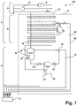
- FIG. 12 shows a pre-cooling circuit 100 with two-stage bath cooling according to a preferred embodiment of the invention.
- the pre-cooling circuit comprises a helium refrigeration system 2 including a compressor system 4 and a heat exchanger system 6 , and a bath cooling system 8 including a first cooling bath tank 34 and a second cooling bath tank 36 .
- a closed pre-cooling circuit (for the consumer to be further cooled) is formed together with a cold delivery device 10, which is set up for heat exchange with at least one consumer to be cooled, with helium being used as the cooling medium.
- the compressor system 4 comprises at least one compressor 16 which compresses helium flowing back through a return line 18 .
- a pressure of the backflow helium is typically around 1.05 bar.
- a pressure of the compressed helium is typically in the range of 7 to 18 bar, preferably in the range of 10 to 15 bar.
- Drawn-in heat dissipation device can be provided, via which heat can be dissipated to the environment.
- the compressed helium is fed to a feed line 30 via a feed line 20 .
- the return line 18 and the feed line 20 pass through the heat exchange system 6 so that a heat exchange between the returning helium and the compressed helium in counterflow is possible.
- one or more turbines 22 can be provided in the refrigeration system 2, via which compressed helium, which is taken from the supply line at a point in the heat exchanger system 6, is expanded to the pressure level of the supply line, and the back-flowing helium in the return line at a (possibly other) place in the heat exchanger system is fed back, so that in principle a Brayton cycle is formed.
- the supply line 30 running through the bath cooling system 8 first runs through a first heat exchanger 40 arranged in a footwell of the first cooling bath tank 34 and then through a second heat exchanger 42 arranged in a footwell of the second cooling bath tank 36.
- the cooling bath tanks are each set up in such a way that in the footwell a helium bath, i.e. helium in the liquid state, and there is helium vapor in the headspace which is in equilibrium with the liquid helium in the footwell.
- a pressure, i.e. an equilibrium pressure, in the cooling bath tank can therefore be assigned a corresponding temperature (corresponding to the vapor pressure curve).
- the pressure is preferably about 1.25 bar, i.e.
- the pressure is preferably about 0.5 bar, i.e. in the range of 0.4 bar to 0.65 bar.
- the base of the first cooling bath container 34 is connected via a line to the second cooling bath container 36 or its head space in order to be able to supply helium to the latter, with a valve 54 being provided in the line in order to be able to control this helium supply.
- a temperature of the helium that is supplied to the cold emitting device 10 can be lowered to 3.6 K or less.
- the helium After the helium has been fed via the feed line 30 to the cold delivery device 10 and used by the cold delivery device to cool the at least one consumer, the helium is passed from the cold delivery device into the return line 32 .
- the return line 32 is connected to an ejector 50 so that helium returned through the return line from the cold dispenser can be used as a motive flow in the ejector to draw helium vapor from the second cooling bath vessel 36 and pressurize it to the pressure of the first cooling bath vessel 34 and expel it.
- a motive flow port of the ejector is connected to the return line
- a suction port of the ejector is connected to the head space of the second cooling bath tank (via a line)
- a discharge port of the ejector is connected to the head space of the first cooling bath tank (via a line). In this way, further liquefaction of the helium in the pre-cooling circuit can be avoided.
- a valve 52 is preferably provided in the connecting line between the head space of the second cooling bath container 36 and the ejector 50 or its suction opening, in order to be able to control the steam flow from the head space of the second cooling bath container to the ejector.
- the head space of the first cooling bath container 34 is connected to the return line 20 of the refrigeration system 2 so that the helium circuit is closed.
- a shield current supply line 80 and a shield current return line 82 are provided, with compressed helium taken from the heat exchanger system 6 or the supply line 18 being routed to the consumer via the shield current supply line 80 and the helium being fed back into the heat exchanger system 6 via the shield current return line 82, e.g the turbines 22.
- the elements of the pre-cooling circuit are preferably arranged in a cold box 12, ie surrounded by heat-insulating walls.
- the lines to and from the cold dispenser 10 are surrounded by heat insulating walls. Each indicated by dashed lines.
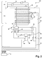
- figure 2 shows a pre-cooling circuit 200 with a variably designed two-stage bath cooling according to another preferred embodiment of the invention.
- This embodiment largely corresponds to that in figure 1 embodiment shown. In the following, therefore, essentially only different or additional elements are discussed and elements that are already associated with are explained again figure 1 were explained.
- a secondary return line 58 is also provided here.
- the secondary return line is connected to a branch from the return line 32 so that helium coming from the cold dispenser 10 can be partially diverted from the return line.
- Valves 60, 62 are provided in the sub-return line and the return line to control the flow of helium into the sub-return line and the return line, respectively.
- the secondary return line 58 leads through a fourth heat exchanger 46 arranged in the footwell of the first cooling bath tank 34 and is then brought back together with the return line 32 before the ejector 50 .
- the pre-cooling circuit can thus be used with different loads, since the helium flow is essentially determined by the operating point of the ejector. For example, a different number of consumers to be cooled can be supplied with cold via the cold delivery device 10 .
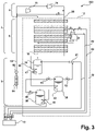
- figure 3 shows a pre-cooling circuit 300 with a three-stage bath cooling according to a further preferred embodiment of the invention.
- This embodiment largely corresponds to that in figure 1 embodiment shown. In the following, therefore, essentially only different or additional elements are discussed and elements that are already associated with are explained again figure 1 were explained.
- This embodiment also includes a third cooling bath tank 38, the supply line 32 after the second cooling bath tank 36 through a footwell in the third cooling bath container 38 arranged third heat exchanger 44 is performed.
- the third cooling bath tank 38 there is again an equilibrium between liquid helium in the foot space and helium vapor in the head space.
- the pressure is preferably about 0.2 bar, ie in the range from 0.1 bar to 0.3 bar. In this way, a further reduction in the temperature of the helium supplied through the supply line to the cold-dispensing device can be achieved. For example, a temperature below 3 K can be reached.
- a vacuum pump 64 is connected via a line to a headspace of the third cooling bath vessel 38 and is configured to pump helium vapor from the headspace.
- the pumped-out helium is fed into the return line 18 of the refrigeration system 2 via a line 68 in which a compressor 66 is arranged.
- the compressor serves to raise the pressure of the helium to the level in the return line.
- the foot space of the first cooling bath container 34 is connected via a line to the third cooling bath container 38 or its head space in order to be able to supply helium to it, with a valve 56 being provided in the line in order to be able to control this helium supply.
- FIG. 2 It is also possible the embodiments of figures 2 and 3 to combine, ie in accordance with the execution figure 2 additionally a third cooling stage, ie a third cooling bath tank, a vacuum pump, a compressor and the corresponding lines/valves according to figure 3 to foresee.
- a corresponding pre-cooling circuit 400 is in figure 4 shown. All elements of this pre-cooling circuit have already been discussed in connection with the Figures 1 to 3 explained.
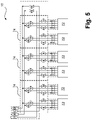
- FIG. 1 shows a cold delivery device 10 which is connected to consumers 72 to be cooled, in particular mixing cryostats.
- This cold dispenser 10 can in particular for each of the versions according to the figures 1 , 2 , 3 be used.
- the assignment of the connections is marked in the figures by arrows which are provided with the letters 'A', 'B', 'C' and 'D'.
- the cold dispensing device 10 comprises a plurality of (here, for example three) valve groups 74, in each of which lines connected to the supply line 32 or the return line 34 lead to individual consumers or consumer groups 72 are provided. These lines are provided with valves in the valve groups so that the helium can be routed from the supply line to individual consumers and from there to the return line.
- the loads 72 are thus independently connectable and disconnectable to the supply ('A') and return ('B') lines. This is especially true with the pre-cooling circuits 200, 400's figures 2 and 4 advantageous, which allow partial load operation.
- Valve assemblies 74 also provide conduit and valves for shield refrigerant flow to be routed from the shield power supply line ('C') to the loads and back to the shield power return line ('D'). So a shield circuit is formed.
- a cold box or several cold boxes are preferably provided again, within which the valve groups and preferably also consumers, in particular the mixing cryostats, are arranged.
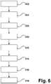
- figure 6 shows the method according to the invention according to a preferred embodiment.
- the individual steps are part of a cycle that the helium goes through.
- the returning helium is compressed (such as by the compressor system).
- the pressure achieved is in the range from 7 to 18 bar, preferably from 10 to 15 bar.
- the compressed helium is passed through a first cooling bath and a subsequent second cooling bath in step 604 to maintain helium in a supercritical state.
- the helium is passed through a third cooling bath.
- the cooling baths are in equilibrium with a respective first, second and third helium vapor.
- the equilibrium pressure corresponds to the pressure mentioned above in connection with the first, second and third cooling bath containers.
- step 610 the supercritical helium is routed to a cold delivery device which is in heat exchange with the at least one consumer to be cooled.
- a reverse flow of helium from the cold dispenser is directed to a motive flow port of an ejector.
- diverting at least a portion of the reflux to form a secondary reflux passing the secondary reflux through the first cooling bath, and then passing it into the reflux.
- step 616 the ejector draws in the second helium vapor that is in equilibrium with the second cooling bath and feeds the first helium vapor that is in equilibrium with the first cooling bath.
- the first helium vapor is vented at step 618 to yield the reverse flow helium, which is compressed at step 602 to complete the cycle.
Landscapes
- Engineering & Computer Science (AREA)
- Physics & Mathematics (AREA)
- Thermal Sciences (AREA)
- Mechanical Engineering (AREA)
- General Engineering & Computer Science (AREA)
- Microelectronics & Electronic Packaging (AREA)
- Containers, Films, And Cooling For Superconductive Devices (AREA)
Priority Applications (7)
| Application Number | Priority Date | Filing Date | Title |
|---|---|---|---|
| EP21020348.5A EP4116639A1 (de) | 2021-07-05 | 2021-07-05 | Vorkühlkreis und verfahren zur helium-kälteversorgung |
| JP2023579098A JP2024523917A (ja) | 2021-07-05 | 2022-07-04 | ヘリウム冷却供給のための予冷回路及び方法 |
| PCT/EP2022/025306 WO2023280439A1 (de) | 2021-07-05 | 2022-07-04 | Vorkühlkreis und verfahren zur helium-kälteversorgung |
| KR1020237045404A KR20240054924A (ko) | 2021-07-05 | 2022-07-04 | 헬륨 냉각을 공급하는 예냉 회로 및 방법 |
| US18/575,596 US20240302081A1 (en) | 2021-07-05 | 2022-07-04 | Pre-cooling circuit and method for supplying helium refrigeration |
| CN202280044589.8A CN117545968A (zh) | 2021-07-05 | 2022-07-04 | 供应氦冷量的预冷回路和方法 |
| EP22737751.2A EP4367449A1 (de) | 2021-07-05 | 2022-07-04 | Vorkühlkreis und verfahren zur helium-kälteversorgung |
Applications Claiming Priority (1)
| Application Number | Priority Date | Filing Date | Title |
|---|---|---|---|
| EP21020348.5A EP4116639A1 (de) | 2021-07-05 | 2021-07-05 | Vorkühlkreis und verfahren zur helium-kälteversorgung |
Publications (1)
| Publication Number | Publication Date |
|---|---|
| EP4116639A1 true EP4116639A1 (de) | 2023-01-11 |
Family
ID=76807460
Family Applications (2)
| Application Number | Title | Priority Date | Filing Date |
|---|---|---|---|
| EP21020348.5A Withdrawn EP4116639A1 (de) | 2021-07-05 | 2021-07-05 | Vorkühlkreis und verfahren zur helium-kälteversorgung |
| EP22737751.2A Pending EP4367449A1 (de) | 2021-07-05 | 2022-07-04 | Vorkühlkreis und verfahren zur helium-kälteversorgung |
Family Applications After (1)
| Application Number | Title | Priority Date | Filing Date |
|---|---|---|---|
| EP22737751.2A Pending EP4367449A1 (de) | 2021-07-05 | 2022-07-04 | Vorkühlkreis und verfahren zur helium-kälteversorgung |
Country Status (6)
| Country | Link |
|---|---|
| US (1) | US20240302081A1 (enExample) |
| EP (2) | EP4116639A1 (enExample) |
| JP (1) | JP2024523917A (enExample) |
| KR (1) | KR20240054924A (enExample) |
| CN (1) | CN117545968A (enExample) |
| WO (1) | WO2023280439A1 (enExample) |
Cited By (2)
| Publication number | Priority date | Publication date | Assignee | Title |
|---|---|---|---|---|
| US20220128272A1 (en) * | 2020-10-23 | 2022-04-28 | Illuminated Extractors, Ltd. | Heating and refrigeration system |
| CN116428759A (zh) * | 2023-06-13 | 2023-07-14 | 北京中科富海低温科技有限公司 | 一种用于长距离运输低温流体的制冷系统和方法 |
Families Citing this family (1)
| Publication number | Priority date | Publication date | Assignee | Title |
|---|---|---|---|---|
| US12566023B2 (en) * | 2022-12-14 | 2026-03-03 | International Business Machines Corporation | Modular cooling farm for cryogenic application |
Citations (3)
| Publication number | Priority date | Publication date | Assignee | Title |
|---|---|---|---|---|
| FR1573734A (enExample) * | 1967-07-27 | 1969-07-04 | ||
| US4209657A (en) * | 1976-05-31 | 1980-06-24 | Tokyo Shibaura Electric Co., Ltd. | Apparatus for immersion-cooling superconductor |
| SU918717A1 (ru) * | 1980-05-20 | 1982-04-07 | Предприятие П/Я А-7904 | Циркул ционна система криостатировани |
Family Cites Families (6)
| Publication number | Priority date | Publication date | Assignee | Title |
|---|---|---|---|---|
| CH501321A (de) * | 1968-12-19 | 1970-12-31 | Sulzer Ag | Verfahren zum Kühlen eines Verbrauchers, der aus einem teilweise stabilisierten Supraleitungsmagneten besteht |
| NL7315487A (nl) * | 1973-11-13 | 1975-05-15 | Philips Nv | 3he-4he verdunningskoelmachine. |
| US4346563A (en) * | 1981-05-15 | 1982-08-31 | Cvi Incorporated | Super critical helium refrigeration process and apparatus |
| JP2964055B2 (ja) * | 1991-11-20 | 1999-10-18 | 日本酸素株式会社 | 超臨界ヘリウム発生装置 |
| GB201210927D0 (en) * | 2012-06-20 | 2012-08-01 | Oxford Instr Nanotechnology Tools Ltd | Reduction of blockages in a cryogenic refrigerator system |
| FR3107586B1 (fr) * | 2020-02-21 | 2022-11-18 | Air Liquide | Dispositif et procédé de réfrigération à dilution |
-
2021
- 2021-07-05 EP EP21020348.5A patent/EP4116639A1/de not_active Withdrawn
-
2022
- 2022-07-04 US US18/575,596 patent/US20240302081A1/en active Pending
- 2022-07-04 KR KR1020237045404A patent/KR20240054924A/ko active Pending
- 2022-07-04 WO PCT/EP2022/025306 patent/WO2023280439A1/de not_active Ceased
- 2022-07-04 EP EP22737751.2A patent/EP4367449A1/de active Pending
- 2022-07-04 JP JP2023579098A patent/JP2024523917A/ja active Pending
- 2022-07-04 CN CN202280044589.8A patent/CN117545968A/zh active Pending
Patent Citations (3)
| Publication number | Priority date | Publication date | Assignee | Title |
|---|---|---|---|---|
| FR1573734A (enExample) * | 1967-07-27 | 1969-07-04 | ||
| US4209657A (en) * | 1976-05-31 | 1980-06-24 | Tokyo Shibaura Electric Co., Ltd. | Apparatus for immersion-cooling superconductor |
| SU918717A1 (ru) * | 1980-05-20 | 1982-04-07 | Предприятие П/Я А-7904 | Циркул ционна система криостатировани |
Cited By (3)
| Publication number | Priority date | Publication date | Assignee | Title |
|---|---|---|---|---|
| US20220128272A1 (en) * | 2020-10-23 | 2022-04-28 | Illuminated Extractors, Ltd. | Heating and refrigeration system |
| US12135149B2 (en) * | 2020-10-23 | 2024-11-05 | Illuminated Extractors, Ltd. | Heating and refrigeration system |
| CN116428759A (zh) * | 2023-06-13 | 2023-07-14 | 北京中科富海低温科技有限公司 | 一种用于长距离运输低温流体的制冷系统和方法 |
Also Published As
| Publication number | Publication date |
|---|---|
| WO2023280439A1 (de) | 2023-01-12 |
| EP4367449A1 (de) | 2024-05-15 |
| KR20240054924A (ko) | 2024-04-26 |
| US20240302081A1 (en) | 2024-09-12 |
| CN117545968A (zh) | 2024-02-09 |
| JP2024523917A (ja) | 2024-07-02 |
Similar Documents
| Publication | Publication Date | Title |
|---|---|---|
| EP4367449A1 (de) | Vorkühlkreis und verfahren zur helium-kälteversorgung | |
| DE60315197T2 (de) | Methode zum Fördern kryogener Flüssigkeiten | |
| DE69937127T2 (de) | Station und Verfahren zur Verteilung von Gas | |
| DE112019005717T5 (de) | Fluid-bypass-verfahren und -system zur steuerung der temperatur eines nicht-petroleum-kraftstoffs | |
| DE102009021442A1 (de) | Verteiltes Kühlsystem | |
| DE69211237T2 (de) | Vakuumbehälter mit einem gekühlten Element | |
| DE102017110560A1 (de) | Kältemittelkreislauf einer Kälteanlage mit einer Anordnung zum Abtauen eines Wärmeübertragers und Verfahren zum Betreiben des Kältemittelkreislaufs | |
| DE1960975C3 (de) | Kühlvorrichtung für Flüssigkeiten | |
| EP4343196A1 (de) | Vorrichtung zum transfer von flüssigem helium, mit verringerten transfer-verlusten | |
| DE102020117235A1 (de) | Kryogene Analysesysteme und Verfahren | |
| EP3749903B1 (de) | Verfahren und vorrichtung zum kühlen eines supraleitenden stromträgers | |
| DE102020130063A1 (de) | Temperieranlage und Verfahren zum Betreiben einer Temperieranlage | |
| DE102020201455A1 (de) | System sowie Verfahren zur Klimatisierung eines Fahrzeuginnenraums und gleichzeitigen Kühlung einer Fahrzeugbatterie für ein elektrisches Fahrzeug | |
| EP4153899B1 (de) | Brenngasversorgungssystem und verfahren zum versorgen eines hochdruck-gaseinspritzmotors mit brenngas | |
| DE102021105999B4 (de) | Verfahren und Vorrichtung zur Rückverflüssigung von BOG | |
| EP1026461B1 (de) | Verfahren und Vorrichtung zur Kühlung von Stromzuführung | |
| EP4004349A1 (de) | Druckregelung für geschlossene joule-kreisprozesse | |
| EP4162215B1 (de) | Verfahren und vorrichtung zum kryogenen kühlen eines verbrauchers | |
| EP3511650B1 (de) | Verfahren und vorrichtung zum kühlen eines verbrauchers sowie system mit entsprechender vorrichtung und verbraucher | |
| EP3580503B1 (de) | Verfahren zum kühlen eines verbrauchers | |
| DE19719376C2 (de) | Verfahren und Vorrichtung zum Anwärmen eines aus einem Speicherbehälter abgezogenen verflüssigten Gases oder Gasgemisches | |
| DE102020133808A1 (de) | Vorrichtung, System und Verfahren zum Kühlen eines Mediums | |
| EP3511649B1 (de) | Verfahren und vorrichtung zum kühlen eines verbrauchers sowie system mit entsprechender vorrichtung und verbraucher | |
| AT527753B1 (de) | Kryogenes Energiespeichersystem und Verfahren zum Speichern von Energie | |
| DE102011112911A1 (de) | Kälteanlage |
Legal Events
| Date | Code | Title | Description |
|---|---|---|---|
| PUAI | Public reference made under article 153(3) epc to a published international application that has entered the european phase |
Free format text: ORIGINAL CODE: 0009012 |
|
| STAA | Information on the status of an ep patent application or granted ep patent |
Free format text: STATUS: THE APPLICATION HAS BEEN PUBLISHED |
|
| AK | Designated contracting states |
Kind code of ref document: A1 Designated state(s): AL AT BE BG CH CY CZ DE DK EE ES FI FR GB GR HR HU IE IS IT LI LT LU LV MC MK MT NL NO PL PT RO RS SE SI SK SM TR |
|
| STAA | Information on the status of an ep patent application or granted ep patent |
Free format text: STATUS: THE APPLICATION IS DEEMED TO BE WITHDRAWN |
|
| 18D | Application deemed to be withdrawn |
Effective date: 20230712 |