EP4116639A1 - Pre-cooling circuit and method for supplying helium coolant - Google Patents
Pre-cooling circuit and method for supplying helium coolant Download PDFInfo
- Publication number
- EP4116639A1 EP4116639A1 EP21020348.5A EP21020348A EP4116639A1 EP 4116639 A1 EP4116639 A1 EP 4116639A1 EP 21020348 A EP21020348 A EP 21020348A EP 4116639 A1 EP4116639 A1 EP 4116639A1
- Authority
- EP
- European Patent Office
- Prior art keywords
- helium
- cooling
- cooling bath
- return line
- cold
- Prior art date
- Legal status (The legal status is an assumption and is not a legal conclusion. Google has not performed a legal analysis and makes no representation as to the accuracy of the status listed.)
- Withdrawn
Links
- 238000001816 cooling Methods 0.000 title claims abstract description 170
- 229910052734 helium Inorganic materials 0.000 title claims abstract description 148
- 239000001307 helium Substances 0.000 title claims abstract description 148
- SWQJXJOGLNCZEY-UHFFFAOYSA-N helium atom Chemical compound [He] SWQJXJOGLNCZEY-UHFFFAOYSA-N 0.000 title claims abstract description 146
- 238000000034 method Methods 0.000 title claims description 13
- 239000002826 coolant Substances 0.000 title description 2
- 239000007788 liquid Substances 0.000 claims description 10
- 238000010992 reflux Methods 0.000 claims description 10
- 238000005057 refrigeration Methods 0.000 claims description 9
- 230000001419 dependent effect Effects 0.000 claims description 2
- 238000010926 purge Methods 0.000 claims 1
- 239000012530 fluid Substances 0.000 description 3
- 150000002371 helium Chemical class 0.000 description 2
- 239000000203 mixture Substances 0.000 description 2
- 230000010349 pulsation Effects 0.000 description 2
- 230000000712 assembly Effects 0.000 description 1
- 238000000429 assembly Methods 0.000 description 1
- 230000015572 biosynthetic process Effects 0.000 description 1
- 230000006835 compression Effects 0.000 description 1
- 238000007906 compression Methods 0.000 description 1
- 238000005265 energy consumption Methods 0.000 description 1
- 230000017525 heat dissipation Effects 0.000 description 1
- 239000003380 propellant Substances 0.000 description 1
- 239000003507 refrigerant Substances 0.000 description 1
- 238000013022 venting Methods 0.000 description 1
Images


Classifications
-
- F—MECHANICAL ENGINEERING; LIGHTING; HEATING; WEAPONS; BLASTING
- F25—REFRIGERATION OR COOLING; COMBINED HEATING AND REFRIGERATION SYSTEMS; HEAT PUMP SYSTEMS; MANUFACTURE OR STORAGE OF ICE; LIQUEFACTION SOLIDIFICATION OF GASES
- F25B—REFRIGERATION MACHINES, PLANTS OR SYSTEMS; COMBINED HEATING AND REFRIGERATION SYSTEMS; HEAT PUMP SYSTEMS
- F25B1/00—Compression machines, plants or systems with non-reversible cycle
- F25B1/10—Compression machines, plants or systems with non-reversible cycle with multi-stage compression
-
- F—MECHANICAL ENGINEERING; LIGHTING; HEATING; WEAPONS; BLASTING
- F25—REFRIGERATION OR COOLING; COMBINED HEATING AND REFRIGERATION SYSTEMS; HEAT PUMP SYSTEMS; MANUFACTURE OR STORAGE OF ICE; LIQUEFACTION SOLIDIFICATION OF GASES
- F25B—REFRIGERATION MACHINES, PLANTS OR SYSTEMS; COMBINED HEATING AND REFRIGERATION SYSTEMS; HEAT PUMP SYSTEMS
- F25B40/00—Subcoolers, desuperheaters or superheaters
-
- F—MECHANICAL ENGINEERING; LIGHTING; HEATING; WEAPONS; BLASTING
- F25—REFRIGERATION OR COOLING; COMBINED HEATING AND REFRIGERATION SYSTEMS; HEAT PUMP SYSTEMS; MANUFACTURE OR STORAGE OF ICE; LIQUEFACTION SOLIDIFICATION OF GASES
- F25B—REFRIGERATION MACHINES, PLANTS OR SYSTEMS; COMBINED HEATING AND REFRIGERATION SYSTEMS; HEAT PUMP SYSTEMS
- F25B41/00—Fluid-circulation arrangements
- F25B41/20—Disposition of valves, e.g. of on-off valves or flow control valves
- F25B41/24—Arrangement of shut-off valves for disconnecting a part of the refrigerant cycle, e.g. an outdoor part
-
- F—MECHANICAL ENGINEERING; LIGHTING; HEATING; WEAPONS; BLASTING
- F25—REFRIGERATION OR COOLING; COMBINED HEATING AND REFRIGERATION SYSTEMS; HEAT PUMP SYSTEMS; MANUFACTURE OR STORAGE OF ICE; LIQUEFACTION SOLIDIFICATION OF GASES
- F25B—REFRIGERATION MACHINES, PLANTS OR SYSTEMS; COMBINED HEATING AND REFRIGERATION SYSTEMS; HEAT PUMP SYSTEMS
- F25B5/00—Compression machines, plants or systems, with several evaporator circuits, e.g. for varying refrigerating capacity
- F25B5/02—Compression machines, plants or systems, with several evaporator circuits, e.g. for varying refrigerating capacity arranged in parallel
-
- F—MECHANICAL ENGINEERING; LIGHTING; HEATING; WEAPONS; BLASTING
- F25—REFRIGERATION OR COOLING; COMBINED HEATING AND REFRIGERATION SYSTEMS; HEAT PUMP SYSTEMS; MANUFACTURE OR STORAGE OF ICE; LIQUEFACTION SOLIDIFICATION OF GASES
- F25B—REFRIGERATION MACHINES, PLANTS OR SYSTEMS; COMBINED HEATING AND REFRIGERATION SYSTEMS; HEAT PUMP SYSTEMS
- F25B9/00—Compression machines, plants or systems, in which the refrigerant is air or other gas of low boiling point
- F25B9/002—Compression machines, plants or systems, in which the refrigerant is air or other gas of low boiling point characterised by the refrigerant
-
- F—MECHANICAL ENGINEERING; LIGHTING; HEATING; WEAPONS; BLASTING
- F25—REFRIGERATION OR COOLING; COMBINED HEATING AND REFRIGERATION SYSTEMS; HEAT PUMP SYSTEMS; MANUFACTURE OR STORAGE OF ICE; LIQUEFACTION SOLIDIFICATION OF GASES
- F25B—REFRIGERATION MACHINES, PLANTS OR SYSTEMS; COMBINED HEATING AND REFRIGERATION SYSTEMS; HEAT PUMP SYSTEMS
- F25B9/00—Compression machines, plants or systems, in which the refrigerant is air or other gas of low boiling point
- F25B9/08—Compression machines, plants or systems, in which the refrigerant is air or other gas of low boiling point using ejectors
-
- F—MECHANICAL ENGINEERING; LIGHTING; HEATING; WEAPONS; BLASTING
- F25—REFRIGERATION OR COOLING; COMBINED HEATING AND REFRIGERATION SYSTEMS; HEAT PUMP SYSTEMS; MANUFACTURE OR STORAGE OF ICE; LIQUEFACTION SOLIDIFICATION OF GASES
- F25B—REFRIGERATION MACHINES, PLANTS OR SYSTEMS; COMBINED HEATING AND REFRIGERATION SYSTEMS; HEAT PUMP SYSTEMS
- F25B2341/00—Details of ejectors not being used as compression device; Details of flow restrictors or expansion valves
- F25B2341/001—Ejectors not being used as compression device
- F25B2341/0011—Ejectors with the cooled primary flow at reduced or low pressure
-
- F—MECHANICAL ENGINEERING; LIGHTING; HEATING; WEAPONS; BLASTING
- F25—REFRIGERATION OR COOLING; COMBINED HEATING AND REFRIGERATION SYSTEMS; HEAT PUMP SYSTEMS; MANUFACTURE OR STORAGE OF ICE; LIQUEFACTION SOLIDIFICATION OF GASES
- F25B—REFRIGERATION MACHINES, PLANTS OR SYSTEMS; COMBINED HEATING AND REFRIGERATION SYSTEMS; HEAT PUMP SYSTEMS
- F25B2400/00—General features or devices for refrigeration machines, plants or systems, combined heating and refrigeration systems or heat-pump systems, i.e. not limited to a particular subgroup of F25B
- F25B2400/07—Details of compressors or related parts
- F25B2400/075—Details of compressors or related parts with parallel compressors
-
- F—MECHANICAL ENGINEERING; LIGHTING; HEATING; WEAPONS; BLASTING
- F25—REFRIGERATION OR COOLING; COMBINED HEATING AND REFRIGERATION SYSTEMS; HEAT PUMP SYSTEMS; MANUFACTURE OR STORAGE OF ICE; LIQUEFACTION SOLIDIFICATION OF GASES
- F25B—REFRIGERATION MACHINES, PLANTS OR SYSTEMS; COMBINED HEATING AND REFRIGERATION SYSTEMS; HEAT PUMP SYSTEMS
- F25B2400/00—General features or devices for refrigeration machines, plants or systems, combined heating and refrigeration systems or heat-pump systems, i.e. not limited to a particular subgroup of F25B
- F25B2400/23—Separators
Definitions
- the invention relates to a pre-cooling circuit and a method for supplying helium to cool at least one consumer to be cooled.
- Cooling temperatures well below 1 K are required in basic research and for cooling quantum computers.
- state-of-the-art mixing cryostats are used, which are pre-cooled to the range of 3 - 4 K with pulsation tube, Sterling or Gifford-McMahon coolers.
- a low pre-cooling temperature is a prerequisite for the efficiency of the mixing cryostat.
- the cooling capacity of these pre-cooling machines is in the range of just a few watts with additional cooling capacity of 50 K as shield cooling. For this reason, mixing cryostats are each equipped with 2 pulsation tube coolers, for example.
- the (closed) pre-cooling circuit for supplying helium cold to at least one consumer to be cooled comprises a supply line and a return line which are connected to one another via a cold emission device, the cold emission device being set up to exchange heat with the at least one consumer to be cooled; a helium chiller configured to dissipate heat to the environment, compress backflow helium, and direct the compressed helium into the supply line; a first and a second cooling bath tank, wherein the supply line runs through a first heat exchanger arranged in a foot space of the first cooling bath tank and subsequently in the direction of the cold delivery device through a second heat exchanger arranged in a foot space of the second cooling bath tank, and wherein a head space of the first cooling bath tank via a return line connected to the helium refrigeration system for supplying the returning helium thereto; and an ejector having a motive flow port, a suction port and a discharge port, wherein the motive flow port is connected to the return line, the suction
- a pre-cooling circuit makes it possible to convey the helium compressed by the compression system to the consumer in a supercritical state, thus avoiding the occurrence of a two-phase mixture (gaseous and liquid helium) which is difficult to control.
- the helium After passing through the consumer, the helium still has sufficient pressure to raise the helium vapor of the second cooling bath container to the pressure of the first cooling bath container by means of the ejector. In total This enables the use of multi-stage bath cooling so that a low temperature can be achieved.
- the at least one consumer to be cooled is preferably a mixing cryostat.
- a secondary return line is preferably provided, which is branched off from the return line after the consumer, runs through a fourth heat exchanger arranged in the footwell of the first cooling bath tank, and opens into the return line in front of the motive flow opening of the ejector, with more preferably in the secondary return line and/or or at least one valve is arranged in the return line parallel to the secondary return line in order to control the flow through the secondary return line.
- the pre-cooling circuit comprises a third cooling bath tank, with the supply line following the second cooling bath tank running through a third heat exchanger arranged in a foot space of the third cooling bath tank, and with a head space of the third cooling bath tank being connected to a vacuum pump which is set up to evacuate helium vapor from the Pump headspace and supply it to the helium cooling system, with a compressor preferably being provided which raises a pressure level of the pumped-out helium to a pressure level of the helium cooling system. This makes it possible to reach a lower temperature.
- the first cooling bath container is adapted to receive liquid helium in the footwell that is in equilibrium with helium vapor in the headspace, with a pressure in the range of 1.0 bar to 1.5 bar
- the second cooling bath container is adapted to receive liquid helium in the footwell accommodate helium in equilibrium with helium vapor in the headspace, a second equilibrium pressure preferably being in the range of 0.4 bar to 0.65 bar
- the third cooling bath vessel is adapted to accommodate liquid helium in the footwell which is in equilibrium with Helium vapor is in the headspace, with a third equilibrium pressure preferably being in the range of 0.1 bar to 0.3 bar.
- temperatures of less than or equal to 3.6 K can be achieved.
- the helium cooling system preferably comprises at least one compressor and is set up to compress helium to a pressure in the range from 7 bar to 18 bar, preferably in the range from 10 bar to 15 bar.
- the high pressure avoids the formation of a two-phase helium mixture.
- the helium cooling system preferably comprises a heat exchanger system, with the return-flowing helium being passed through the heat exchanger system in countercurrent to the compressed helium.
- the refrigeration delivery device comprises a shield circuit; and the helium refrigerator is configured to provide a helium shield flow, the helium shield flow being routed from the helium refrigerator to the shield circuit and from there back to the helium refrigerator.
- the helium refrigerator is configured to provide a helium shield flow, the helium shield flow being routed from the helium refrigerator to the shield circuit and from there back to the helium refrigerator.
- the cold output device is preferably set up to exchange heat with a number of consumers to be cooled, with the consumers being able to be connected and disconnected to the supply line and the return line independently of one another. It is therefore possible to vary the number of consumers.
- a low-temperature system comprises a (closed) pre-cooling circuit according to the invention and at least one mixing cryostat, which is connected to the cold delivery device as the at least one consumer to be cooled; wherein the cold delivery device is preferably set up in such a way that the supply line and the return line are connected to at least one helium bath of the at least one mixing cryostat.
- At least one sample is placed in the at least one mixing cryostat of a low-temperature system according to the invention and cooled to a temperature below 1K.
- the method according to the invention for helium refrigeration supply of at least one consumer to be cooled comprises compressing backflowing helium; passing the compressed helium through a first cooling bath and a subsequent second cooling bath to keep helium in a supercritical state; conducting the supercritical helium to a refrigeration delivery device which is in heat exchange with the at least one consumer to be cooled; directing a return flow of the helium from the cold dispenser to a motive flow port of an ejector; drawing a second helium vapor in equilibrium with the second cooling bath by the ejector and supplying it to a first helium vapor in equilibrium with the first cooling bath; and venting the first helium vapor to obtain the reverse flow helium.
- the process further comprises diverting at least a portion of the recycle stream to form a secondary recycle stream; passing the secondary reflux through the first cooling bath and then into the reflux.
- the method includes passing the compressed helium through a third cooling bath after the second cooling bath.
- this application speaks of a 'cooling supply' or a 'cooling release' by the pre-cooling circuit, or it is said that 'a consumer is supplied with coldness' or that 'coldness is released to a consumer'.
- This is to be understood in the sense that the pre-cooling circuit absorbs and dissipates heat from the consumer (by means of a respective heat exchange device).
- 'conduit' or 'conduit' refers to conduits for fluids, particularly helium, which is preferably gaseous. It means pipes or pipelines.
- 'connected' refers to the fact that there is a fluid connection via a (pipe) line. In all cases, valves can be provided which influence or control the fluid flow through the line.
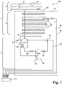
- FIG. 12 shows a pre-cooling circuit 100 with two-stage bath cooling according to a preferred embodiment of the invention.
- the pre-cooling circuit comprises a helium refrigeration system 2 including a compressor system 4 and a heat exchanger system 6 , and a bath cooling system 8 including a first cooling bath tank 34 and a second cooling bath tank 36 .
- a closed pre-cooling circuit (for the consumer to be further cooled) is formed together with a cold delivery device 10, which is set up for heat exchange with at least one consumer to be cooled, with helium being used as the cooling medium.
- the compressor system 4 comprises at least one compressor 16 which compresses helium flowing back through a return line 18 .
- a pressure of the backflow helium is typically around 1.05 bar.
- a pressure of the compressed helium is typically in the range of 7 to 18 bar, preferably in the range of 10 to 15 bar.
- Drawn-in heat dissipation device can be provided, via which heat can be dissipated to the environment.
- the compressed helium is fed to a feed line 30 via a feed line 20 .
- the return line 18 and the feed line 20 pass through the heat exchange system 6 so that a heat exchange between the returning helium and the compressed helium in counterflow is possible.
- one or more turbines 22 can be provided in the refrigeration system 2, via which compressed helium, which is taken from the supply line at a point in the heat exchanger system 6, is expanded to the pressure level of the supply line, and the back-flowing helium in the return line at a (possibly other) place in the heat exchanger system is fed back, so that in principle a Brayton cycle is formed.
- the supply line 30 running through the bath cooling system 8 first runs through a first heat exchanger 40 arranged in a footwell of the first cooling bath tank 34 and then through a second heat exchanger 42 arranged in a footwell of the second cooling bath tank 36.
- the cooling bath tanks are each set up in such a way that in the footwell a helium bath, i.e. helium in the liquid state, and there is helium vapor in the headspace which is in equilibrium with the liquid helium in the footwell.
- a pressure, i.e. an equilibrium pressure, in the cooling bath tank can therefore be assigned a corresponding temperature (corresponding to the vapor pressure curve).
- the pressure is preferably about 1.25 bar, i.e.
- the pressure is preferably about 0.5 bar, i.e. in the range of 0.4 bar to 0.65 bar.
- the base of the first cooling bath container 34 is connected via a line to the second cooling bath container 36 or its head space in order to be able to supply helium to the latter, with a valve 54 being provided in the line in order to be able to control this helium supply.
- a temperature of the helium that is supplied to the cold emitting device 10 can be lowered to 3.6 K or less.
- the helium After the helium has been fed via the feed line 30 to the cold delivery device 10 and used by the cold delivery device to cool the at least one consumer, the helium is passed from the cold delivery device into the return line 32 .
- the return line 32 is connected to an ejector 50 so that helium returned through the return line from the cold dispenser can be used as a motive flow in the ejector to draw helium vapor from the second cooling bath vessel 36 and pressurize it to the pressure of the first cooling bath vessel 34 and expel it.
- a motive flow port of the ejector is connected to the return line
- a suction port of the ejector is connected to the head space of the second cooling bath tank (via a line)
- a discharge port of the ejector is connected to the head space of the first cooling bath tank (via a line). In this way, further liquefaction of the helium in the pre-cooling circuit can be avoided.
- a valve 52 is preferably provided in the connecting line between the head space of the second cooling bath container 36 and the ejector 50 or its suction opening, in order to be able to control the steam flow from the head space of the second cooling bath container to the ejector.
- the head space of the first cooling bath container 34 is connected to the return line 20 of the refrigeration system 2 so that the helium circuit is closed.
- a shield current supply line 80 and a shield current return line 82 are provided, with compressed helium taken from the heat exchanger system 6 or the supply line 18 being routed to the consumer via the shield current supply line 80 and the helium being fed back into the heat exchanger system 6 via the shield current return line 82, e.g the turbines 22.
- the elements of the pre-cooling circuit are preferably arranged in a cold box 12, ie surrounded by heat-insulating walls.
- the lines to and from the cold dispenser 10 are surrounded by heat insulating walls. Each indicated by dashed lines.
- figure 2 shows a pre-cooling circuit 200 with a variably designed two-stage bath cooling according to another preferred embodiment of the invention.
- This embodiment largely corresponds to that in figure 1 embodiment shown. In the following, therefore, essentially only different or additional elements are discussed and elements that are already associated with are explained again figure 1 were explained.
- a secondary return line 58 is also provided here.
- the secondary return line is connected to a branch from the return line 32 so that helium coming from the cold dispenser 10 can be partially diverted from the return line.
- Valves 60, 62 are provided in the sub-return line and the return line to control the flow of helium into the sub-return line and the return line, respectively.
- the secondary return line 58 leads through a fourth heat exchanger 46 arranged in the footwell of the first cooling bath tank 34 and is then brought back together with the return line 32 before the ejector 50 .
- the pre-cooling circuit can thus be used with different loads, since the helium flow is essentially determined by the operating point of the ejector. For example, a different number of consumers to be cooled can be supplied with cold via the cold delivery device 10 .
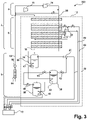
- figure 3 shows a pre-cooling circuit 300 with a three-stage bath cooling according to a further preferred embodiment of the invention.
- This embodiment largely corresponds to that in figure 1 embodiment shown. In the following, therefore, essentially only different or additional elements are discussed and elements that are already associated with are explained again figure 1 were explained.
- This embodiment also includes a third cooling bath tank 38, the supply line 32 after the second cooling bath tank 36 through a footwell in the third cooling bath container 38 arranged third heat exchanger 44 is performed.
- the third cooling bath tank 38 there is again an equilibrium between liquid helium in the foot space and helium vapor in the head space.
- the pressure is preferably about 0.2 bar, ie in the range from 0.1 bar to 0.3 bar. In this way, a further reduction in the temperature of the helium supplied through the supply line to the cold-dispensing device can be achieved. For example, a temperature below 3 K can be reached.
- a vacuum pump 64 is connected via a line to a headspace of the third cooling bath vessel 38 and is configured to pump helium vapor from the headspace.
- the pumped-out helium is fed into the return line 18 of the refrigeration system 2 via a line 68 in which a compressor 66 is arranged.
- the compressor serves to raise the pressure of the helium to the level in the return line.
- the foot space of the first cooling bath container 34 is connected via a line to the third cooling bath container 38 or its head space in order to be able to supply helium to it, with a valve 56 being provided in the line in order to be able to control this helium supply.
- FIG. 2 It is also possible the embodiments of figures 2 and 3 to combine, ie in accordance with the execution figure 2 additionally a third cooling stage, ie a third cooling bath tank, a vacuum pump, a compressor and the corresponding lines/valves according to figure 3 to foresee.
- a corresponding pre-cooling circuit 400 is in figure 4 shown. All elements of this pre-cooling circuit have already been discussed in connection with the Figures 1 to 3 explained.
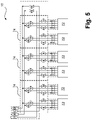
- FIG. 1 shows a cold delivery device 10 which is connected to consumers 72 to be cooled, in particular mixing cryostats.
- This cold dispenser 10 can in particular for each of the versions according to the figures 1 , 2 , 3 be used.
- the assignment of the connections is marked in the figures by arrows which are provided with the letters 'A', 'B', 'C' and 'D'.
- the cold dispensing device 10 comprises a plurality of (here, for example three) valve groups 74, in each of which lines connected to the supply line 32 or the return line 34 lead to individual consumers or consumer groups 72 are provided. These lines are provided with valves in the valve groups so that the helium can be routed from the supply line to individual consumers and from there to the return line.
- the loads 72 are thus independently connectable and disconnectable to the supply ('A') and return ('B') lines. This is especially true with the pre-cooling circuits 200, 400's figures 2 and 4 advantageous, which allow partial load operation.
- Valve assemblies 74 also provide conduit and valves for shield refrigerant flow to be routed from the shield power supply line ('C') to the loads and back to the shield power return line ('D'). So a shield circuit is formed.
- a cold box or several cold boxes are preferably provided again, within which the valve groups and preferably also consumers, in particular the mixing cryostats, are arranged.
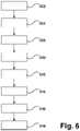
- figure 6 shows the method according to the invention according to a preferred embodiment.
- the individual steps are part of a cycle that the helium goes through.
- the returning helium is compressed (such as by the compressor system).
- the pressure achieved is in the range from 7 to 18 bar, preferably from 10 to 15 bar.
- the compressed helium is passed through a first cooling bath and a subsequent second cooling bath in step 604 to maintain helium in a supercritical state.
- the helium is passed through a third cooling bath.
- the cooling baths are in equilibrium with a respective first, second and third helium vapor.
- the equilibrium pressure corresponds to the pressure mentioned above in connection with the first, second and third cooling bath containers.
- step 610 the supercritical helium is routed to a cold delivery device which is in heat exchange with the at least one consumer to be cooled.
- a reverse flow of helium from the cold dispenser is directed to a motive flow port of an ejector.
- diverting at least a portion of the reflux to form a secondary reflux passing the secondary reflux through the first cooling bath, and then passing it into the reflux.
- step 616 the ejector draws in the second helium vapor that is in equilibrium with the second cooling bath and feeds the first helium vapor that is in equilibrium with the first cooling bath.
- the first helium vapor is vented at step 618 to yield the reverse flow helium, which is compressed at step 602 to complete the cycle.
Abstract
Bereitgestellt wird ein Vorkühlkreis zur Helium-Kälteversorgung wenigstens eines zu kühlenden Verbrauchers (72), umfassend eine Zuleitung (30) und eine Rückleitung (32), die über eine Kälteabgabeeinrichtung (10) miteinander verbunden sind, wobei die Kälteabgabeeinrichtung eingerichtet ist, Wärme mit dem wenigstens einen zu kühlenden Verbraucher zu tauschen; eine Helium-Kühlanlage (2), die eingerichtet ist, Wärme an die Umgebung abzugeben, rückströmendes Helium zu verdichten und das verdichtete Helium in die Zuleitung zu leiten; einen ersten und einen zweiten Kühlbadbehälter (34, 36), wobei die Zuleitung durch einen in einem Fußraum des ersten Kühlbadbehälters (34) angeordneten ersten Wärmetauscher (40) und in Richtung der Kälteabgabeeinrichtung nachfolgend durch einen in einem Fußraum des zweiten Kühlbadbehälters (36) angeordneten zweiten Wärmetauscher (42) verläuft, und wobei ein Kopfraum des ersten Kühlbadbehälters über eine Rückführleitung (18) mit der Helium-Kühlanlage verbunden ist; einen Ejektor (50), wobei eine Treibstrom-Öffnung mit der Rückleitung verbunden ist, eine Ansaug-Öffnung mit einem Kopfraum des zweiten Kühlbadbehälters verbunden ist, und eine Ausstoß-Öffnung mit dem Kopfraum des ersten Kühlbadbehälters verbunden ist, wobei der Ejektor eingerichtet ist, von der Kälteabgabeeinrichtung rückströmendes Helium als Treibstrom zu verwenden, um Heliumdampf aus dem zweiten Kühlbadbehälter anzusaugen und auf den Druck des ersten Kühlbadbehälters anzuheben.A pre-cooling circuit is provided for the helium cold supply of at least one consumer (72) to be cooled, comprising a supply line (30) and a return line (32), which are connected to one another via a cold output device (10), the cold output device being set up to transfer heat to the to exchange at least one consumer to be cooled; a helium cooling system (2) which is set up to give off heat to the environment, to compress backflowing helium and to direct the compressed helium into the feed line; a first and a second cooling bath container (34, 36), the supply line being arranged in a foot space of the first cooling bath container (34) through a first heat exchanger (40) and subsequently in the direction of the cold delivery device through one arranged in a foot space of the second cooling bath container (36). second heat exchanger (42) and wherein a headspace of the first cooling bath vessel is connected to the helium cooling system via a return line (18); an ejector (50), wherein a motive flow port is connected to the return line, a suction port is connected to a head space of the second cooling bath tank, and a discharge port is connected to the head space of the first cooling bath tank, the ejector being arranged, using helium returning from the cold dispenser as a motive flow to draw in helium vapor from the second cooling bath vessel and pressurize it to the pressure of the first cooling bath vessel.
Description
Die Erfindung betrifft einen Vorkühlkreis und ein Verfahren zur Helium-Kälteversorgung wenigstens eines zu kühlenden Verbrauchers.The invention relates to a pre-cooling circuit and a method for supplying helium to cool at least one consumer to be cooled.
In der Grundlagenforschung wie auch zur Kühlung von Quantencomputern werden Kühltemperaturen weit unterhalb von 1 K benötigt. Dazu werden nach heutigem Stand der Technik Mischungskryostate eingesetzt, die mit Pulsationsrohr-, Sterling- oder Gifford-McMahon-Kühler bis in den Bereich von 3 - 4 K vorgekühlt werden. Eine tiefe Vorkühltemperatur ist Voraussetzung für die Effizienz des Mischungskryostats. Die Kälteleistung dieser Vorkühlmaschinen liegt im Bereich von nur wenigen Watt mit zusätzlicher Kühlleistung bei 50 K als Schildkühlung. Daher werden Mischungskryostate z.B. jeweils mit 2 Pulsationsrohrkühlern ausgerüstet.Cooling temperatures well below 1 K are required in basic research and for cooling quantum computers. For this purpose, state-of-the-art mixing cryostats are used, which are pre-cooled to the range of 3 - 4 K with pulsation tube, Sterling or Gifford-McMahon coolers. A low pre-cooling temperature is a prerequisite for the efficiency of the mixing cryostat. The cooling capacity of these pre-cooling machines is in the range of just a few watts with additional cooling capacity of 50 K as shield cooling. For this reason, mixing cryostats are each equipped with 2 pulsation tube coolers, for example.
Mit dem Fortschritt insbesondere in der Quantencomputer-Forschung steigt der Leistungsbedarf an Vorkühlung stark an. Der Wirkungsgrad der oben genannten Vorkühlsysteme ist jedoch sehr niedrig. Dies fällt bei kleineren Anwendungen nicht sonderlich ins Gewicht, bestimmend ist hier der generell hohe Anschaffungspreis des Mischungskryostaten. Bei mehrfacher Anordnung der Vorkühlsysteme steigt jedoch der Energieverbrauch linear an, so dass die resultierenden Betriebskosten signifikant werden. Sollen zusätzlich mehrere Mischungskryostate für z.B. mehrere Quantencomputer betrieben werden, vervielfältigt sich das Problem.With the progress, especially in quantum computer research, the power requirement for pre-cooling increases sharply. However, the efficiency of the above pre-cooling systems is very low. This is not particularly important for smaller applications, the generally high purchase price of the mixing cryostat is decisive here. However, if the pre-cooling systems are arranged multiple times, the energy consumption increases linearly, so that the resulting operating costs become significant. If, in addition, several mixing cryostats are to be operated, e.g. for several quantum computers, the problem is multiplied.
Es besteht also Bedarf an einem effizienten Vorkühlsystem, das in der Lage ist, ein oder mehrere Mischungskryostate mit Kälte, insbesondere Heliumkälte, möglichst tiefer Temperatur zu versorgen, wobei die Kältezufuhr bzw. Kälteleistung, insbesondere im Falle mehrerer Mischungskryostate, variabel sein sollte.There is therefore a need for an efficient pre-cooling system that is able to supply one or more mixing cryostats with cold, in particular helium cold, at the lowest possible temperature, with the cold supply or cooling capacity, especially in the case of several mixing cryostats, being variable.
Diese Aufgabe wird gelöst durch einen Vorkühlkreis und ein Verfahren zur Helium-Kälteversorgung wenigstens eines zu kühlenden Verbrauchers mit den Merkmalen der unabhängigen Ansprüche. Abhängige Ansprüche betreffen bevorzugte Ausführungsformen.This object is achieved by a pre-cooling circuit and a method for helium cooling supply of at least one consumer to be cooled with the features of the independent claims. Dependent claims relate to preferred embodiments.
Der (geschlossene) Vorkühlkreis zur Helium-Kälteversorgung wenigstens eines zu kühlenden Verbrauchers, umfasst eine Zuleitung und eine Rückleitung, die über eine Kälteabgabeeinrichtung miteinander verbunden sind, wobei die Kälteabgabeeinrichtung dazu eingerichtet ist, Wärme mit dem wenigstens einen zu kühlenden Verbraucher zu tauschen; eine Helium-Kühlanlage, die dazu eingerichtet ist, Wärme an die Umgebung abzugeben, rückströmendes Helium zu verdichten und das verdichtete Helium in die Zuleitung zu leiten; einen ersten und einen zweiten Kühlbadbehälter, wobei die Zuleitung durch einen in einem Fußraum des ersten Kühlbadbehälters angeordneten ersten Wärmetauscher und in Richtung der Kälteabgabeeinrichtung nachfolgend durch einen in einem Fußraum des zweiten Kühlbadbehälters angeordneten zweiten Wärmetauscher verläuft, und wobei ein Kopfraum des ersten Kühlbadbehälters über eine Rückführleitung mit der Helium-Kühlanlage verbunden ist, um dieser das rückströmende Helium zuzuführen; und einen Ejektor mit einer Treibstrom-Öffnung, einer Ansaug-Öffnung und einer Ausstoß-Öffnung, wobei die Treibstrom-Öffnung mit der Rückleitung verbunden ist, die Ansaug-Öffnung mit einem Kopfraum des zweiten Kühlbadbehälters verbunden ist, und die Ausstoß-Öffnung mit dem Kopfraum des ersten Kühlbadbehälters verbunden ist, wobei der Ejektor eingerichtet ist, durch die Rückleitung von der Kälteabgabeeinrichtung rückströmendes Helium als Treibstrom zu verwenden, um Heliumdampf aus dem zweiten Kühlbadbehälter anzusaugen und auf den Druck des ersten Kühlbadbehälters anzuheben. Der Begriff "Fußraum" ist auch als "Sumpfraum" bekannt.The (closed) pre-cooling circuit for supplying helium cold to at least one consumer to be cooled comprises a supply line and a return line which are connected to one another via a cold emission device, the cold emission device being set up to exchange heat with the at least one consumer to be cooled; a helium chiller configured to dissipate heat to the environment, compress backflow helium, and direct the compressed helium into the supply line; a first and a second cooling bath tank, wherein the supply line runs through a first heat exchanger arranged in a foot space of the first cooling bath tank and subsequently in the direction of the cold delivery device through a second heat exchanger arranged in a foot space of the second cooling bath tank, and wherein a head space of the first cooling bath tank via a return line connected to the helium refrigeration system for supplying the returning helium thereto; and an ejector having a motive flow port, a suction port and a discharge port, wherein the motive flow port is connected to the return line, the suction port is connected to a headspace of the second cooling bath vessel, and the discharge port is connected to the Headspace of the first cooling bath vessel is connected, wherein the ejector is arranged to use helium flowing back through the return line from the cold delivery device as a motive current to draw in helium vapor from the second cooling bath vessel and raise it to the pressure of the first cooling bath vessel. The term "foot room" is also known as "swamp room".
Durch einen erfindungsgemäßen Vorkühlkreis wird ermöglicht, das von dem Kompressionssystem verdichtete Helium in einem überkritischen Zustand zum Verbraucher zu leiten, so dass das Auftreten eines schwer zu kontrollierenden Zweiphasengemisches (gasförmiges und flüssiges Helium) vermieden wird. Dabei weist das Helium nach Durchlaufen des Verbrauchers immer noch einen ausreichenden Druck auf, um mittels des Ejektors den Heliumdampf des zweiten Kühlbadbehälters auf den Druck des ersten Kühlbadbehälters anzuheben. Insgesamt wird so der Einsatz einer mehrstufigen Badkühlung ermöglicht, so dass eine tiefe Temperatur erreicht werden kann.A pre-cooling circuit according to the invention makes it possible to convey the helium compressed by the compression system to the consumer in a supercritical state, thus avoiding the occurrence of a two-phase mixture (gaseous and liquid helium) which is difficult to control. After passing through the consumer, the helium still has sufficient pressure to raise the helium vapor of the second cooling bath container to the pressure of the first cooling bath container by means of the ejector. In total This enables the use of multi-stage bath cooling so that a low temperature can be achieved.
Bevorzugt handelt es sich bei dem wenigstens einen zu kühlenden Verbraucher um einen Mischungskryostat.The at least one consumer to be cooled is preferably a mixing cryostat.
Bevorzugt ist eine Nebenrückleitung vorgesehen, die nach dem Verbraucher von der Rückleitung abgezweigt ist, durch einen in dem Fußraum des ersten Kühlbadbehälters angeordneten vierten Wärmetauscher verläuft, und vor der Treibstrom-Öffnung des Ejektors in die Rückleitung mündet, wobei weiter bevorzugt in der Nebenrückleitung und/oder in der Rückleitung parallel zur Nebenrückleitung wenigstens ein Ventil angeordnet ist, um den Durchfluss durch die Nebenrückleitung zu steuern. Dies ermöglicht einen Teillastbetrieb des Vorkühlkreises, so dass insbesondere eine variable Anzahl von Verbrauchern mit Kälte versorgt werden kann.A secondary return line is preferably provided, which is branched off from the return line after the consumer, runs through a fourth heat exchanger arranged in the footwell of the first cooling bath tank, and opens into the return line in front of the motive flow opening of the ejector, with more preferably in the secondary return line and/or or at least one valve is arranged in the return line parallel to the secondary return line in order to control the flow through the secondary return line. This enables partial load operation of the pre-cooling circuit, so that in particular a variable number of consumers can be supplied with cold.
Bevorzugt umfasst der Vorkühlkreis einen dritten Kühlbadbehälter, wobei die Zuleitung nachfolgend auf den zweiten Kühlbadbehälter durch einen in einem Fußraum des dritten Kühlbadbehälters angeordneten dritten Wärmetauscher verläuft, und wobei ein Kopfraum des dritten Kühlbadbehälters mit einer Vakuumpumpe verbunden ist, die dazu eingerichtet ist, Heliumdampf aus dem Kopfraum abzupumpen und der Helium-Kühlanlage zuzuführen, wobei bevorzugt ein Verdichter vorgesehen ist, der ein Druckniveau des abgepumpten Heliums auf ein Druckniveau der Helium-Kühlanlage anhebt. Hierdurch wird ermöglicht, eine tiefere Temperatur zu erreichen.Preferably, the pre-cooling circuit comprises a third cooling bath tank, with the supply line following the second cooling bath tank running through a third heat exchanger arranged in a foot space of the third cooling bath tank, and with a head space of the third cooling bath tank being connected to a vacuum pump which is set up to evacuate helium vapor from the Pump headspace and supply it to the helium cooling system, with a compressor preferably being provided which raises a pressure level of the pumped-out helium to a pressure level of the helium cooling system. This makes it possible to reach a lower temperature.
Bevorzugt ist der erste Kühlbadbehälter dazu eingerichtet, im Fußraum flüssiges Helium aufzunehmen, das im Gleichgewicht mit Heliumdampf im Kopfraum steht, wobei ein im Bereich von 1,0 bar bis 1,5 bar liegt, und der zweite Kühlbadbehälter ist dazu eingerichtet, im Fußraum flüssiges Helium aufzunehmen, das im Gleichgewicht mit Heliumdampf im Kopfraum steht, wobei ein zweiter Gleichgewichtsdruck bevorzugt im Bereich von 0,4 bar bis 0,65 bar liegt, und gegebenenfalls ist der dritte Kühlbadbehälter dazu eingerichtet, im Fußraum flüssiges Helium aufzunehmen, das im Gleichgewicht mit Heliumdampf im Kopfraum steht, wobei ein dritter Gleichgewichtsdruck bevorzugt im Bereich von 0,1 bar bis 0,3 bar liegt. Im zweistufigen Fall lassen sich so Temperaturen kleiner oder gleich 3,6 K erreichen. Im dreistufigen Fall lassen sich so Temperaturen kleiner 3 K erreichen
Bevorzugt umfasst die Helium-Kühlanlage wenigstens einen Kompressor und ist dazu eingerichtet Helium auf einen Druck im Bereich von 7 bar bis 18 bar, bevorzugt im Bereich von 10 bar bis 15 bar, zu verdichten. Durch den hohen Druck lässt sich das Entstehen eines Zweiphasen-Heliumgemisches vermeiden.Preferably, the first cooling bath container is adapted to receive liquid helium in the footwell that is in equilibrium with helium vapor in the headspace, with a pressure in the range of 1.0 bar to 1.5 bar, and the second cooling bath container is adapted to receive liquid helium in the footwell accommodate helium in equilibrium with helium vapor in the headspace, a second equilibrium pressure preferably being in the range of 0.4 bar to 0.65 bar, and optionally the third cooling bath vessel is adapted to accommodate liquid helium in the footwell which is in equilibrium with Helium vapor is in the headspace, with a third equilibrium pressure preferably being in the range of 0.1 bar to 0.3 bar. In the two-stage case, temperatures of less than or equal to 3.6 K can be achieved. In the three-stage case, temperatures below 3 K can be achieved
The helium cooling system preferably comprises at least one compressor and is set up to compress helium to a pressure in the range from 7 bar to 18 bar, preferably in the range from 10 bar to 15 bar. The high pressure avoids the formation of a two-phase helium mixture.
Bevorzugt umfasst die Helium-Kühlanlage ein Wärmetauschersystem, wobei das rückströmende Helium im Gegenstrom zum verdichteten Helium durch das Wärmetauschersystem geleitet wird.The helium cooling system preferably comprises a heat exchanger system, with the return-flowing helium being passed through the heat exchanger system in countercurrent to the compressed helium.
Weiterhin umfasst bevorzugt die Kälteabgabeeinrichtung einen Schildkreislauf umfasst; und die Helium-Kühlanlage ist dazu eingerichtet, einen Heliumschildstrom bereitzustellen, wobei der Heliumschildstrom von der Helium-Kühlanlage zum Schildkreislauf geleitet und von diesem zurück zur Helium-Kühlanlage geleitet wird. Dadurch kann eine äußere Schild-Kühlung des Verbrauchers versorgt werden.Furthermore, preferably, the refrigeration delivery device comprises a shield circuit; and the helium refrigerator is configured to provide a helium shield flow, the helium shield flow being routed from the helium refrigerator to the shield circuit and from there back to the helium refrigerator. As a result, external shield cooling of the consumer can be supplied.
Bevorzugt ist die Kälteabgabeeinrichtung dazu eingerichtet, Wärme mit mehreren zu kühlenden Verbrauchern zu tauschen, wobei die Verbraucher unabhängig voneinander mit der Zuleitung und der Rückleitung verbindbar und trennbar sind. Es ist also möglich, die Anzahl der Verbraucher zu variieren.The cold output device is preferably set up to exchange heat with a number of consumers to be cooled, with the consumers being able to be connected and disconnected to the supply line and the return line independently of one another. It is therefore possible to vary the number of consumers.
Eine erfindungsgemäße Tieftemperaturanlage umfasst einen erfindungsgemäßen (geschlossenen) Vorkühlkreis und wenigstens einen Mischungskryostat, der als der wenigstens eine zu kühlenden Verbraucher mit der Kälteabgabeeinrichtung verbunden ist; wobei bevorzugt die Kälteabgabeeinrichtung so eingerichtet ist, dass die Zuleitung und die Rückleitung mit wenigstens einem Heliumbad des wenigstens einen Mischungskryostats verbunden sind.A low-temperature system according to the invention comprises a (closed) pre-cooling circuit according to the invention and at least one mixing cryostat, which is connected to the cold delivery device as the at least one consumer to be cooled; wherein the cold delivery device is preferably set up in such a way that the supply line and the return line are connected to at least one helium bath of the at least one mixing cryostat.
In einem erfindungsgemäßen Tieftemperaturverfahren wird wenigstens eine Probe in dem wenigstens einen Mischungskryostat einer erfindungsgemäßen Tieftemperaturanlage platziert und auf eine Temperatur unter 1 K gekühlt.In a low-temperature method according to the invention, at least one sample is placed in the at least one mixing cryostat of a low-temperature system according to the invention and cooled to a temperature below 1K.
Das erfindungsgemäße Verfahren zur Helium-Kälteversorgung wenigstens eines zu kühlenden Verbrauchers, umfasst ein Verdichten rückströmenden Heliums; ein Leiten des verdichteten Heliums durch ein erstes Kühlbad und ein nachfolgendes zweites Kühlbad, um Helium in einem überkritischen Zustand zu erhalten; ein Leiten des überkritischen Heliums zu einer Kälteabgabeeinrichtung, die mit dem wenigstens einen zu kühlenden Verbraucher in Wärmeaustausch steht; ein Leiten eines Rückstroms des Heliums von der Kälteabgabeeinrichtung zu einer Treibstromöffnung eines Ejektors; ein Ansaugen eines zweiten Heliumdampfes, der im Gleichgewicht mit dem zweiten Kühlbad steht, mittels des Ejektors und Zuführen zu einem ersten Heliumdampf, der im Gleichgewicht mit dem ersten Kühlbad steht; und ein Ableiten des ersten Heliumdampfes, um das rückströmende Helium zu erhalten.The method according to the invention for helium refrigeration supply of at least one consumer to be cooled comprises compressing backflowing helium; passing the compressed helium through a first cooling bath and a subsequent second cooling bath to keep helium in a supercritical state; conducting the supercritical helium to a refrigeration delivery device which is in heat exchange with the at least one consumer to be cooled; directing a return flow of the helium from the cold dispenser to a motive flow port of an ejector; drawing a second helium vapor in equilibrium with the second cooling bath by the ejector and supplying it to a first helium vapor in equilibrium with the first cooling bath; and venting the first helium vapor to obtain the reverse flow helium.
Bevorzugt umfasst das Verfahren weiterhin ein Abzweigen mindestens eines Teils des Rückstroms, um einen Nebenrückstrom zu bilden; ein Leiten des Nebenrückstroms durch das erste Kühlbad und anschließend in den Rückstrom.Preferably, the process further comprises diverting at least a portion of the recycle stream to form a secondary recycle stream; passing the secondary reflux through the first cooling bath and then into the reflux.
Vorzugsweise umfasst das Verfahren ein Leiten des verdichteten Heliums durch ein drittes Kühlbad nach dem zweiten Kühlbad.Preferably, the method includes passing the compressed helium through a third cooling bath after the second cooling bath.
In dieser Anmeldung wird zur Vereinfachung von einer 'Kälteversorgung' oder einer 'Kälteabgabe' durch den Vorkühlkreis gesprochen, bzw. davon gesprochen, dass 'ein Verbraucher mit Kälte versorgt wird' oder dass 'Kälte an einen Verbraucher abgegeben wird'. Dies ist jeweils in dem Sinne zu verstehen, dass durch den Vorkühlkreis Wärme vom Verbraucher aufgenommen bzw. abgeführt wird (mittels einer jeweiligen Wärmetauschvorrichtung).For the sake of simplicity, this application speaks of a 'cooling supply' or a 'cooling release' by the pre-cooling circuit, or it is said that 'a consumer is supplied with coldness' or that 'coldness is released to a consumer'. This is to be understood in the sense that the pre-cooling circuit absorbs and dissipates heat from the consumer (by means of a respective heat exchange device).
Der Begriff 'Leitung' bzw. 'leiten' bezieht sich auf Leitungen für Fluide, insbesondere für Helium, das vorzugsweise gasförmig ist. Es sind also Rohre bzw. Rohrleitungen gemeint. Ebenso bezieht sich der Begriff 'verbunden' darauf, dass eine fluidische Verbindung über eine (Rohr-)Leitung besteht. In allen Fällen können Ventile vorgesehen sein, die den Fluidfluss durch die Leitung beeinflussen bzw. steuern.The term 'conduit' or 'conduit' refers to conduits for fluids, particularly helium, which is preferably gaseous. It means pipes or pipelines. Likewise, the term 'connected' refers to the fact that there is a fluid connection via a (pipe) line. In all cases, valves can be provided which influence or control the fluid flow through the line.
Die Erfindung wird nachfolgend unter Bezugnahme auf die beigefügten Zeichnungen näher erläutert, welche die vorliegende Erfindung und ihre Merkmale gegenüber dem Stand der Technik veranschaulichen.The invention will be explained in more detail below with reference to the accompanying drawings, which illustrate the present invention and its features over the prior art.
-
Figur 1 zeigt einen Vorkühlkreis mit zweistufiger Badkühlung gemäß einer bevorzugten Ausführungsform der Erfindung;figure 1 shows a pre-cooling circuit with two-stage bath cooling according to a preferred embodiment of the invention; -
Figur 2 zeigt einen Vorkühlkreis mit einer variabel ausgelegten zweistufigen Badkühlung gemäß einer anderen bevorzugten Ausführungsform der Erfindung;figure 2 shows a pre-cooling circuit with a variably designed two-stage bath cooling according to another preferred embodiment of the invention; -
Figur 3 zeigt einen Vorkühlkreis mit einer dreistufigen Badkühlung gemäß einer weiteren bevorzugten Ausführungsform der Erfindung;figure 3 shows a pre-cooling circuit with a three-stage bath cooling according to a further preferred embodiment of the invention; -
Figur 4 zeigt einen Vorkühlkreis mit einer variabel ausgelegten dreistufigen Badkühlung gemäß einer weiteren bevorzugten Ausführungsform der Erfindung;figure 4 shows a pre-cooling circuit with a variably designed three-stage bath cooling according to a further preferred embodiment of the invention; -
Figur 5 zeigt eine Kälteabgabeeinrichtung, die mit zu kühlenden Verbrauchern, insbesondere Mischungskryostaten, verbunden ist; undfigure 5 shows a cold delivery device which is connected to consumers to be cooled, in particular mixing cryostats; and -
Figur 6 zeigt das erfindungsgemäße Verfahren gemäß einer bevorzugten Ausführungsform.figure 6 shows the method according to the invention according to a preferred embodiment.
Das Kompressorsystem 4 umfasst wenigstens einen Kompressor 16, der durch eine Rückführleitung 18 rückströmendes Helium verdichtet. Ein Druck des rückströmenden Heliums liegt typischerweise bei etwa 1,05 bar. Ein Druck des verdichteten Heliums liegt typischerweise im Bereich von 7 bis 18 bar, vorzugsweise im Bereich von 10 bis 15 bar. Weiterhin kann im oder am Kompressorsystem eine nicht weiter eingezeichnete Wärmeabgabeeinrichtung vorgesehen sein, über die Wärme an die Umgebung abgegeben werden kann.The compressor system 4 comprises at least one
Das verdichtete Helium wird über eine Zuführleitung 20 einer Zuleitung 30 zugeführt. Die Rückführleitung 18 und die Zuführleitung 20 verlaufen durch das Wärmetauschersystem 6, so dass zwischen dem rückströmenden Helium und dem verdichteten Helium im Gegenstrom ein Wärmeaustausch ermöglicht wird.The compressed helium is fed to a
Weiterhin können in der Kälteanlage 2 eine oder mehrere Turbinen 22 vorgesehen sein, über die verdichtetes Helium, das der Zuführleitung an einer Stelle im Wärmetauschersystem 6 entnommen wird, auf das Druckniveau der Zuführleitung entspannt wird, und dem rückströmenden Helium in der Rückführleitung an einer (möglicherweise anderen) Stelle im Wärmetauschersystem wieder zugeführt wird, so dass im Prinzip ein Brayton-Zyklus gebildet wird.Furthermore, one or
Die durch das Badkühlsystem 8 verlaufende Zuleitung 30 verläuft zunächst durch einen in einem Fußraum des ersten Kühlbadbehälters 34 angeordneten ersten Wärmetauscher 40 und anschließend durch einen in einem Fußraum des zweiten Kühlbadbehälters 36 angeordneten zweiten Wärmetauscher 42. Die Kühlbadbehälter sind jeweils so eingerichtet, dass sich im Fußraum ein Heliumbad, d.h. Helium im flüssigen Zustand, befindet und sich im Kopfraum Heliumdampf befindet, der sich im Gelichgewicht mit dem flüssigen Helium im Fußraum befindet. Einem Druck, d.h. einem Gleichgewichtsdruck, im Kühlbadbehälter kann also eine entsprechende Temperatur zugeordnet werden (entsprechend der Dampfdruckkurve). Im ersten Kühlbadbehälter 34 beträgt der Druck vorzugsweise etwa 1,25 bar, d.h. liegt im Bereich von 1,0 bar bis 1,5 bar. Im zweiten Kühlbadbehälter 36 beträgt der Druck vorzugsweise etwa 0,5 bar, d.h. liegt im Bereich von 0,4 bar bis 0,65 bar. Der Fußraum des ersten Kühlbadbehälters 34 ist über eine Leitung mit dem zweiten Kühlbadbehälter 36 bzw. dessen Kopfraum verbunden, um letzteren Helium zuführen zu können, wobei in der Leitung ein Ventil 54 vorgesehen ist, um diese Heliumzuführung steuern zu können.The
Insgesamt kann mittels der zweistufigen Badkühlung (im ersten und zweiten Kühlbadbehälter 34, 36) eine Temperatur des Heliums, das der Kälteabgabeeinrichtung 10 zugeführt wird, auf 3,6 K oder weniger abgesenkt werden.Overall, by means of the two-stage bath cooling (in the first and second
Nachdem das Helium über die Zuleitung 30 der Kälteabgabeeinrichtung 10 zugeleitet und durch die Kälteabgabeeinrichtung zum Kühlen des wenigstens eines Verbrauchers verwendet wurde, wird das Helium von der Kälteabgabeeinrichtung in die Rückleitung 32 geleitet.After the helium has been fed via the
Die Rückleitung 32 ist mit einem Ejektor 50 verbunden, so dass durch die Rückleitung von der Kälteabgabeeinrichtung zurückgeleitetes Helium als Treibstrom im Ejektor verwendet werden kann, um Heliumdampf aus dem zweiten Kühlbadbehälter 36 anzusaugen und auf den Druck des ersten Kühlbadbehälter 34 anzuheben und in diesen auszustoßen. Entsprechend ist eine Treibstromöffnung des Ejektors mit der Rückleitung verbunden, eine Ansaugöffnung des Ejektors mit dem Kopfraum des zweiten Kühlbadbehälters (über eine Leitung) verbunden und eine Ausstoßöffnung des Ejektors mit dem Kopfraum des ersten Kühlbadbehälters (über eine Leitung) verbunden. Eine weitere Verflüssigung des Heliums kann auf diese Weise im Vorkühlkreis vermieden werden. In der Verbindungleitung zwischen Kopfraum des zweiten Kühlbadbehälters 36 und dem Ejektor 50 bzw. dessen Ansaugöffnung ist vorzugsweise ein Ventil 52 vorgesehen, um den Dampfstrom vom Kopfraum des zweiten Kühlbadbehälters zum Ejektor steuern zu können.The
Der Kopfraum des ersten Kühlbadbehälters 34 ist mit der Rückführleitung 20 der Kälteanlage 2 verbunden, so dass der Heliumkreislauf geschlossen wird.The head space of the first
Weiterhin kann vorgesehen sein, einen Schildkältestrom bereitzustellen, der vom Verbraucher für eine äußere Kühlung verwendet werden kann. Dazu sind beispielsweise eine Schildstromzuleitung 80 und eine Schildstromrückleitung 82 vorgesehen, wobei über die Schildstromzuleitung 80 aus dem Wärmetauschersystem 6 bzw. der Zuführleitung 18 entnommenes verdichtetes Helium zum Verbraucher geleitet wird und das Helium über die Schildstromrückleitung 82 wieder in das Wärmetauschersystem 6 eingespeist wird, z.B. über die Turbinen 22.Provision can also be made to provide a shield cold flow that can be used by the consumer for external cooling. For this purpose, for example, a shield
Die Elemente des Vorkühlkreises sind mit Ausnahme des Kompressorsystems 4 vorzugsweise in einer Kältebox 12 angeordnet, d.h. von wärmeisolierenden Wänden umgeben. Ebenso sind die Leitungen zu und von der Kälteabgabeeinrichtung 10 von wärmeisolierenden Wänden umgeben. Jeweils durch gestrichelte Linien angedeutet.With the exception of the compressor system 4, the elements of the pre-cooling circuit are preferably arranged in a
Im Unterschied zu
Die Nebenrückleitung 58 führt durch einen im Fußraum des ersten Kühlbadbehälters 34 angeordneten vierten Wärmetauscher 46 und wird anschießend, vor dem Ejektor 50, wieder mit der Rückleitung 32 zusammengeführt. Durch die Kühlung des durch die Nebenrückleitung geleiteten Teils des Heliums kann die Temperatur an der Treibstromöffnung des Ejektors beeinflusst werden, was eine Einstellung (indirekt, mittels der Ventile 60, 62 in der Nebenrückleitung bzw. Rückleitung) des Betriebspunkts des Ejektors 50 ermöglicht. Der Vorkühlkreis kann somit mit unterschiedlichen Belastungen benutzt werden, da der Heliumfluss wesentlich durch den Betriebspunkt des Ejektors bestimmt ist. Z.B. können unterschiedlich viele zu kühlende Verbraucher über die Kälteabgabeeinrichtung 10 mit Kälte versorgt werden.The
Diese Ausführung umfasst zusätzlich einen dritten Kühlbadbehälter 38, wobei die Zuleitung 32 nach dem zweiten Kühlbadbehälter 36 durch einen in einem Fußraum des dritten Kühlbadbehälters 38 angeordneten dritten Wärmetauscher 44 geführt wird. Im dritten Kühlbadbehälter 38 liegt wieder ein Gleichgewicht zwischen flüssigem Helium im Fußraum und Heliumdampf im Kopfraum vor. Der Druck beträgt dabei vorzugsweise etwa 0,2 bar, d.h. liegt im Bereich von 0,1 bar bis 0,3 bar. Auf diese Weise kann eine weitere Temperaturabsenkung des durch die Zuleitung der Kälteabgabeeinrichtung zugeführten Heliums erreicht werden. Beispielsweise kann eine Temperatur unter 3 K erreicht werden.This embodiment also includes a third
Eine Vakuumpumpe 64 ist über eine Leitung mit einem Kopfraum des dritten Kühlbadbehälters 38 verbunden und eingerichtet, Heliumdampf aus dem Kopfraum abzupumpen. Das abgepumpte Helium wird über eine Leitung 68, in der ein Verdichter 66 angeordnet ist, in die Rückführleitung 18 der Kälteanlage 2 geleitet. Der Verdichter dient dazu, den Druck des Heliums auf das Niveau in der Rückführleitung anzuheben.A
Der Fußraum des ersten Kühlbadbehälters 34 ist über eine Leitung mit dem dritten Kühlbadbehälter 38 bzw. dessen Kopfraum verbunden, um diesem Helium zuführen zu können, wobei in der Leitung ein Ventil 56 vorgesehen ist, um diese Heliumzuführung steuern zu können.The foot space of the first
Es ist ebenso möglich die Ausführungsformen der
Die Kälteabgabeeinrichtung 10 umfasst mehrere (hier beispielsweise drei) Ventilgruppen 74, in denen jeweils mit der Zuleitung 32 bzw. der Rückleitung 34 verbundene Leitungen zu einzelnen Verbrauchern oder Verbrauchergruppen 72 vorgesehen sind. Diese Leitungen sind in den Ventilgruppen mit Ventilen versehen, so dass das Helium aus der Zuleitung gezielt zu einzelnen Verbrauchern geleitet und von diesen in die Rückleitung geleitet werden kann. Die Verbraucher 72 sind also in unabhängiger Weise voneinander mit der Zuleitung ('A') und der Rückleitung ('B') verbindbar und trennbar. Dies ist besonders zusammen mit den Vorkühlkreisen 200, 400 der
In den Ventilgruppen 74 wird ebenso Leitungen und Ventile für einen Schildkältestrom vorgesehen, über die dieser von der Schildstromzuleitung ('C') zu den Verbrauchern und wieder zurück zu der Schildstromrückleitung ('D') geleitet werden kann. Es wird also ein Schildkreislauf gebildet.
Vorzugsweise ist wieder eine Kältebox oder sind mehrere Kälteboxen vorgesehen, innerhalb derer die Ventilgruppen und vorzugsweise auch Verbraucher, insbesondere die Mischungskryostaten, angeordnet sind.A cold box or several cold boxes are preferably provided again, within which the valve groups and preferably also consumers, in particular the mixing cryostats, are arranged.
Das verdichte Helium wird in Schritt 604 durch ein erstes Kühlbad und ein nachfolgendes zweites Kühlbad geleitet, um Helium in einem überkritischen Zustand zu erhalten. Im bevorzugten Schritt 606 wird das Helium nach dem zweiten Kühlbad durch ein drittes Kühlbad geleitet. Die Kühlbäder stehen im Gleichgewicht mit einem entsprechenden ersten, zweiten bzw. dritten Heliumdampf. Der Gleichgewichtsdruck entspricht dabei jeweils dem vorstehend im Zusammenhang mit dem ersten, zweiten bzw. dritten Kühlbadbehälter genannten Druck.The compressed helium is passed through a first cooling bath and a subsequent second cooling bath in
Das überkritische Helium wird in Schritt 610 zu einer Kälteabgabeeinrichtung geleitet, die mit dem wenigstens einen zu kühlenden Verbraucher in Wärmeaustausch steht.In
In Schritt 612 wird ein Rückstrom des Heliums von der Kälteabgabeeinrichtung zu einer Treibstromöffnung eines Ejektors geleitet. Optional kann in Schritt 614 ein Abzweigen mindestens eines Teils des Rückstroms, um einen Nebenrückstrom zu bilden, ein Leiten des Nebenrückstroms durch das erste Kühlbad und anschließend ein Leiten in den Rückstrom durchgeführt werden.In
In Schritt 616 erfolgt ein Ansaugen durch den Ejektor des zweiten Heliumdampfes, der im Gleichgewicht mit dem zweiten Kühlbad steht, und ein Zuführen zu dem ersten Heliumdampf, der im Gleichgewicht mit dem ersten Kühlbad steht.In
Der erste Heliumdampf wird in Schritt 618 abgeleitet, um das rückströmende Helium zu erhalten, das in Schritt 602 verdichtet wird, so dass der Kreislauf vervollständigt wird.The first helium vapor is vented at
Claims (13)
einen dritten Kühlbadbehälter (38), wobei die Zuleitung (30) nachfolgend auf den zweiten Kühlbadbehälter durch einen in einem Fußraum des dritten Kühlbadbehälters angeordneten dritten Wärmetauscher (44) verläuft, und wobei ein Kopfraum des dritten Kühlbadbehälters mit einer Vakuumpumpe (64) verbunden ist, die dazu eingerichtet ist, Heliumdampf aus dem Kopfraum abzupumpen und der Helium-Kühlanlage zuzuführen, wobei bevorzugt ein Verdichter (66) vorgesehen ist, der ein Druckniveau des abgepumpten Heliums auf ein Druckniveau der Helium-Kühlanlage anhebt.Pre-cooling circuit (300, 400) according to any one of the preceding claims, comprising
a third cooling bath tank (38), the supply line (30) following the second cooling bath tank passing through a third heat exchanger (44) arranged in a foot space of the third cooling bath tank, and a head space of the third cooling bath tank being connected to a vacuum pump (64), which is set up to pump helium vapor out of the headspace and to supply it to the helium cooling system, a compressor (66) preferably being provided which raises a pressure level of the pumped-out helium to a pressure level of the helium cooling system.
wobei die Helium-Kühlanlage (2) wenigstens einen Kompressor (16) umfasst und dazu eingerichtet ist, Helium auf einen Druck im Bereich von 7 bar bis 18 bar, bevorzugt im Bereich von 10 bar bis 15 bar, zu verdichten.Pre-cooling circuit (100, 200, 300, 400) according to one of the preceding claims,
wherein the helium cooling system (2) comprises at least one compressor (16) and is set up to compress helium to a pressure in the range from 7 bar to 18 bar, preferably in the range from 10 bar to 15 bar.
wobei die Helium-Kühlanlage (2) ein Wärmetauschersystem (6) umfasst, wobei das rückströmende Helium im Gegenstrom zum verdichteten Helium durch das Wärmetauschersystem geleitet wird.Pre-cooling circuit (100, 200, 300, 400) according to claim 5,
wherein the helium cooling system (2) comprises a heat exchanger system (6), the return-flowing helium being passed through the heat exchanger system in countercurrent to the compressed helium.
wobei die Kälteabgabeeinrichtung (10) dazu eingerichtet ist, Wärme mit mehreren zu kühlenden Verbrauchern (72) zu tauschen, wobei die Verbraucher unabhängig voneinander mit der Zuleitung und der Rückleitung verbindbar und trennbar sind.Pre-cooling circuit (100, 200, 300, 400) according to one of the preceding claims,
wherein the cold delivery device (10) is set up to exchange heat with a plurality of consumers (72) to be cooled, the consumers being able to be connected and disconnected to the supply line and the return line independently of one another.
Leiten des verdichteten Heliums durch ein drittes Kühlbad nach dem zweiten Kühlbad.A method according to any one of claims 11 or 12, comprising
Passing the compressed helium through a third cooling bath after the second cooling bath.
Priority Applications (3)
| Application Number | Priority Date | Filing Date | Title |
|---|---|---|---|
| EP21020348.5A EP4116639A1 (en) | 2021-07-05 | 2021-07-05 | Pre-cooling circuit and method for supplying helium coolant |
| CN202280044589.8A CN117545968A (en) | 2021-07-05 | 2022-07-04 | Precooling circuit and method for supplying helium cooling capacity |
| PCT/EP2022/025306 WO2023280439A1 (en) | 2021-07-05 | 2022-07-04 | Pre-cooling circuit and method for supplying helium refrigeration |
Applications Claiming Priority (1)
| Application Number | Priority Date | Filing Date | Title |
|---|---|---|---|
| EP21020348.5A EP4116639A1 (en) | 2021-07-05 | 2021-07-05 | Pre-cooling circuit and method for supplying helium coolant |
Publications (1)
| Publication Number | Publication Date |
|---|---|
| EP4116639A1 true EP4116639A1 (en) | 2023-01-11 |
Family
ID=76807460
Family Applications (1)
| Application Number | Title | Priority Date | Filing Date |
|---|---|---|---|
| EP21020348.5A Withdrawn EP4116639A1 (en) | 2021-07-05 | 2021-07-05 | Pre-cooling circuit and method for supplying helium coolant |
Country Status (3)
| Country | Link |
|---|---|
| EP (1) | EP4116639A1 (en) |
| CN (1) | CN117545968A (en) |
| WO (1) | WO2023280439A1 (en) |
Cited By (2)
| Publication number | Priority date | Publication date | Assignee | Title |
|---|---|---|---|---|
| US20220128272A1 (en) * | 2020-10-23 | 2022-04-28 | Illuminated Extractors, Ltd. | Heating and refrigeration system |
| CN116428759A (en) * | 2023-06-13 | 2023-07-14 | 北京中科富海低温科技有限公司 | Refrigeration system and method for transporting low-temperature fluid in long distance |
Citations (3)
| Publication number | Priority date | Publication date | Assignee | Title |
|---|---|---|---|---|
| FR1573734A (en) * | 1967-07-27 | 1969-07-04 | ||
| US4209657A (en) * | 1976-05-31 | 1980-06-24 | Tokyo Shibaura Electric Co., Ltd. | Apparatus for immersion-cooling superconductor |
| SU918717A1 (en) * | 1980-05-20 | 1982-04-07 | Предприятие П/Я А-7904 | Circulation cryostatting system |
-
2021
- 2021-07-05 EP EP21020348.5A patent/EP4116639A1/en not_active Withdrawn
-
2022
- 2022-07-04 WO PCT/EP2022/025306 patent/WO2023280439A1/en active Application Filing
- 2022-07-04 CN CN202280044589.8A patent/CN117545968A/en active Pending
Patent Citations (3)
| Publication number | Priority date | Publication date | Assignee | Title |
|---|---|---|---|---|
| FR1573734A (en) * | 1967-07-27 | 1969-07-04 | ||
| US4209657A (en) * | 1976-05-31 | 1980-06-24 | Tokyo Shibaura Electric Co., Ltd. | Apparatus for immersion-cooling superconductor |
| SU918717A1 (en) * | 1980-05-20 | 1982-04-07 | Предприятие П/Я А-7904 | Circulation cryostatting system |
Cited By (2)
| Publication number | Priority date | Publication date | Assignee | Title |
|---|---|---|---|---|
| US20220128272A1 (en) * | 2020-10-23 | 2022-04-28 | Illuminated Extractors, Ltd. | Heating and refrigeration system |
| CN116428759A (en) * | 2023-06-13 | 2023-07-14 | 北京中科富海低温科技有限公司 | Refrigeration system and method for transporting low-temperature fluid in long distance |
Also Published As
| Publication number | Publication date |
|---|---|
| WO2023280439A1 (en) | 2023-01-12 |
| CN117545968A (en) | 2024-02-09 |
Similar Documents
| Publication | Publication Date | Title |
|---|---|---|
| WO2023280439A1 (en) | Pre-cooling circuit and method for supplying helium refrigeration | |
| DE102009021442B4 (en) | Distributed cooling system | |
| DE112019005717T5 (en) | FLUID BYPASS PROCESS AND SYSTEM FOR CONTROLLING THE TEMPERATURE OF A NON-PETROLEUM FUEL | |
| DE102016005632A1 (en) | Mixing column for processes with a single mixed refrigerant | |
| DE1960975C3 (en) | Cooling device for liquids | |
| WO2022101139A2 (en) | Temperature control system and method for operating a temperature control system | |
| DE102017110560B4 (en) | Refrigerant circuit of a refrigeration system with an arrangement for defrosting a heat exchanger and a method for operating the refrigerant circuit | |
| DE102017008210B4 (en) | Device and method for filling a mobile refrigerant tank with a cryogenic refrigerant | |
| EP3749903B1 (en) | Method and device for cooling a superconducting current carrier | |
| DE1501101B2 (en) | Device for generating cold and / or for liquefying gases | |
| DE102020117235A1 (en) | Cryogenic analysis systems and processes | |
| EP1026461B1 (en) | Method and device for cooling current supply | |
| DE19908506A1 (en) | Refrigeration using thermal cycle for low boiling point fluid, especially for cooling superconducting components of particle accelerators | |
| EP3511650B1 (en) | Method and device for cooling a consumer and system with corresponding device and consumers | |
| DE102020201455A1 (en) | System and method for air conditioning a vehicle interior and simultaneous cooling of a vehicle battery for an electric vehicle | |
| EP4004349A1 (en) | Pressure control for closed brayton cycles | |
| DE1840441U (en) | COOLING DEVICE. | |
| WO2021245157A1 (en) | Method and device for cryogenic cooling of a consumer | |
| DE102007052259A1 (en) | Fuel supply device for proportional supply of hydrogen to consumer, particularly to internal combustion engine of motor vehicle, for burning gaseous fuel in combustion chamber, has hydrogen storage, particularly cryogenic tank | |
| EP3511649B1 (en) | Method and device for cooling a consumer and system with corresponding device and consumers | |
| DE19719376C2 (en) | Method and device for heating a liquefied gas or gas mixture drawn off from a storage container | |
| DE102011112911A1 (en) | refrigeration plant | |
| DE102021105999B4 (en) | Method and device for reliquefaction of BOG | |
| EP0964156A2 (en) | Pump operating process for boiling refrigerants or coolants | |
| EP3580503B1 (en) | Method for cooling a consumer |
Legal Events
| Date | Code | Title | Description |
|---|---|---|---|
| PUAI | Public reference made under article 153(3) epc to a published international application that has entered the european phase |
Free format text: ORIGINAL CODE: 0009012 |
|
| STAA | Information on the status of an ep patent application or granted ep patent |
Free format text: STATUS: THE APPLICATION HAS BEEN PUBLISHED |
|
| AK | Designated contracting states |
Kind code of ref document: A1 Designated state(s): AL AT BE BG CH CY CZ DE DK EE ES FI FR GB GR HR HU IE IS IT LI LT LU LV MC MK MT NL NO PL PT RO RS SE SI SK SM TR |
|
| STAA | Information on the status of an ep patent application or granted ep patent |
Free format text: STATUS: THE APPLICATION IS DEEMED TO BE WITHDRAWN |
|
| 18D | Application deemed to be withdrawn |
Effective date: 20230712 |