EP4116129A1 - Verfahren und master-steuereinheit zur steuerung eines elektrischen systems eines elektrischen fahrzeugs - Google Patents
Verfahren und master-steuereinheit zur steuerung eines elektrischen systems eines elektrischen fahrzeugs Download PDFInfo
- Publication number
- EP4116129A1 EP4116129A1 EP21184242.2A EP21184242A EP4116129A1 EP 4116129 A1 EP4116129 A1 EP 4116129A1 EP 21184242 A EP21184242 A EP 21184242A EP 4116129 A1 EP4116129 A1 EP 4116129A1
- Authority
- EP
- European Patent Office
- Prior art keywords
- network
- determined
- current value
- battery
- converter
- Prior art date
- Legal status (The legal status is an assumption and is not a legal conclusion. Google has not performed a legal analysis and makes no representation as to the accuracy of the status listed.)
- Pending
Links
Images


Classifications
-
- B—PERFORMING OPERATIONS; TRANSPORTING
- B60—VEHICLES IN GENERAL
- B60L—PROPULSION OF ELECTRICALLY-PROPELLED VEHICLES; SUPPLYING ELECTRIC POWER FOR AUXILIARY EQUIPMENT OF ELECTRICALLY-PROPELLED VEHICLES; ELECTRODYNAMIC BRAKE SYSTEMS FOR VEHICLES IN GENERAL; MAGNETIC SUSPENSION OR LEVITATION FOR VEHICLES; MONITORING OPERATING VARIABLES OF ELECTRICALLY-PROPELLED VEHICLES; ELECTRIC SAFETY DEVICES FOR ELECTRICALLY-PROPELLED VEHICLES
- B60L1/00—Supplying electric power to auxiliary equipment of vehicles
- B60L1/006—Supplying electric power to auxiliary equipment of vehicles to power outlets
-
- B—PERFORMING OPERATIONS; TRANSPORTING
- B60—VEHICLES IN GENERAL
- B60L—PROPULSION OF ELECTRICALLY-PROPELLED VEHICLES; SUPPLYING ELECTRIC POWER FOR AUXILIARY EQUIPMENT OF ELECTRICALLY-PROPELLED VEHICLES; ELECTRODYNAMIC BRAKE SYSTEMS FOR VEHICLES IN GENERAL; MAGNETIC SUSPENSION OR LEVITATION FOR VEHICLES; MONITORING OPERATING VARIABLES OF ELECTRICALLY-PROPELLED VEHICLES; ELECTRIC SAFETY DEVICES FOR ELECTRICALLY-PROPELLED VEHICLES
- B60L53/00—Methods of charging batteries, specially adapted for electric vehicles; Charging stations or on-board charging equipment therefor; Exchange of energy storage elements in electric vehicles
- B60L53/60—Monitoring or controlling charging stations
- B60L53/63—Monitoring or controlling charging stations in response to network capacity
-
- B—PERFORMING OPERATIONS; TRANSPORTING
- B60—VEHICLES IN GENERAL
- B60L—PROPULSION OF ELECTRICALLY-PROPELLED VEHICLES; SUPPLYING ELECTRIC POWER FOR AUXILIARY EQUIPMENT OF ELECTRICALLY-PROPELLED VEHICLES; ELECTRODYNAMIC BRAKE SYSTEMS FOR VEHICLES IN GENERAL; MAGNETIC SUSPENSION OR LEVITATION FOR VEHICLES; MONITORING OPERATING VARIABLES OF ELECTRICALLY-PROPELLED VEHICLES; ELECTRIC SAFETY DEVICES FOR ELECTRICALLY-PROPELLED VEHICLES
- B60L53/00—Methods of charging batteries, specially adapted for electric vehicles; Charging stations or on-board charging equipment therefor; Exchange of energy storage elements in electric vehicles
- B60L53/50—Charging stations characterised by energy-storage or power-generation means
- B60L53/53—Batteries
-
- B—PERFORMING OPERATIONS; TRANSPORTING
- B60—VEHICLES IN GENERAL
- B60L—PROPULSION OF ELECTRICALLY-PROPELLED VEHICLES; SUPPLYING ELECTRIC POWER FOR AUXILIARY EQUIPMENT OF ELECTRICALLY-PROPELLED VEHICLES; ELECTRODYNAMIC BRAKE SYSTEMS FOR VEHICLES IN GENERAL; MAGNETIC SUSPENSION OR LEVITATION FOR VEHICLES; MONITORING OPERATING VARIABLES OF ELECTRICALLY-PROPELLED VEHICLES; ELECTRIC SAFETY DEVICES FOR ELECTRICALLY-PROPELLED VEHICLES
- B60L58/00—Methods or circuit arrangements for monitoring or controlling batteries or fuel cells, specially adapted for electric vehicles
- B60L58/10—Methods or circuit arrangements for monitoring or controlling batteries or fuel cells, specially adapted for electric vehicles for monitoring or controlling batteries
- B60L58/12—Methods or circuit arrangements for monitoring or controlling batteries or fuel cells, specially adapted for electric vehicles for monitoring or controlling batteries responding to state of charge [SoC]
-
- B—PERFORMING OPERATIONS; TRANSPORTING
- B60—VEHICLES IN GENERAL
- B60L—PROPULSION OF ELECTRICALLY-PROPELLED VEHICLES; SUPPLYING ELECTRIC POWER FOR AUXILIARY EQUIPMENT OF ELECTRICALLY-PROPELLED VEHICLES; ELECTRODYNAMIC BRAKE SYSTEMS FOR VEHICLES IN GENERAL; MAGNETIC SUSPENSION OR LEVITATION FOR VEHICLES; MONITORING OPERATING VARIABLES OF ELECTRICALLY-PROPELLED VEHICLES; ELECTRIC SAFETY DEVICES FOR ELECTRICALLY-PROPELLED VEHICLES
- B60L2200/00—Type of vehicles
- B60L2200/40—Working vehicles
-
- Y—GENERAL TAGGING OF NEW TECHNOLOGICAL DEVELOPMENTS; GENERAL TAGGING OF CROSS-SECTIONAL TECHNOLOGIES SPANNING OVER SEVERAL SECTIONS OF THE IPC; TECHNICAL SUBJECTS COVERED BY FORMER USPC CROSS-REFERENCE ART COLLECTIONS [XRACs] AND DIGESTS
- Y02—TECHNOLOGIES OR APPLICATIONS FOR MITIGATION OR ADAPTATION AGAINST CLIMATE CHANGE
- Y02T—CLIMATE CHANGE MITIGATION TECHNOLOGIES RELATED TO TRANSPORTATION
- Y02T10/00—Road transport of goods or passengers
- Y02T10/60—Other road transportation technologies with climate change mitigation effect
- Y02T10/70—Energy storage systems for electromobility, e.g. batteries
Definitions
- the invention relates to a method for controlling an electrical system of an electric vehicle.
- the invention relates to a method for controlling an electrical system of an electric heavy-duty vehicle.
- the invention relates to a master control unit for controlling an electrical system of an electric vehicle.
- the invention relates to a master control unit for controlling an electrical system of an electric heavy-duty vehicle.
- the invention relates to a computer program and relates to a computer readable medium carrying a computer program.
- the invention relates to an electrical system of an electric vehicle, in particular an electric heavy-duty vehicle.
- the invention relates to an electric vehicle, in particular an electric heavy-duty vehicle.
- the invention can be applied in heavy-duty vehicles, such as trucks, buses and construction equipment.
- the invention can be applied to a garbage truck, a mixer, a crane or alike.
- the invention will be described - in particular - with respect to a heavy-duty vehicle, the invention is not restricted to this particular vehicle, but may also be used in other vehicles such as a car.
- KR 101439060 B1 discloses a vehicle battery control apparatus.
- the vehicle battery control apparatus includes a high voltage battery, a low voltage DC converter, an auxiliary low voltage battery and an electronic load controller.
- the high-voltage battery is supplied with the voltage that is down from the main power source of the fuel cell or the like, and can supply power to the low-voltage DC converter.
- the low voltage DC converter may reduce the high voltage received from the high voltage battery to a low voltage to charge the auxiliary low voltage battery.
- the auxiliary low-voltage battery is charged with electric power supplied from the low-voltage DC converter, and can supply auxiliary electric power to a plurality of electronic loads inside the vehicle.
- KR 101439060 B1 relates to the field of passenger cars. It does not deal with the problem of external loads (body builder loads) added a posteriori by the vehicle owner.
- WO 2019/238 203 A1 discloses a method of operating a vehicle electrical system.
- the vehicle electrical system includes an electrical power source configured to supply a first DC voltage at a first voltage level and a DC/DC converter coupled to the electrical power source and configured to supply a second DC voltage at a second voltage level that is different from the first voltage level.
- the method comprises the steps of monitoring a level of current supplied by the DC/DC converter, determining, based on monitoring of the level of the current, that the DC/DC converter is saturated, and in response to determining that the DC/DC converter is saturated, regulating a level of voltage output by the DC/DC converter.
- US 2012/0306263 A1 discloses a control device for an electrically powered vehicle, mounted to the electrically powered vehicle.
- the control device comprises a current control element that takes off a charging current to be supplied to a low voltage battery that supplies power to auxiliary equipment mounted to the electrically powered vehicle in order to charge up the low voltage battery from an output current on the low voltage battery side of a voltage conversion device that performs voltage conversion between voltage of a high voltage battery that, along with supplying power to a motor that propels the electrically powered vehicle and power to the auxiliary equipment, charges up the low Voltage battery and Voltage of the low Voltage battery.
- the control device further comprises an integrated control unit that determines a charging current value for the charging current based upon accumulated power information related to power accumulated in the low voltage battery and conversion efficiency of the Voltage conversion by the Voltage conversion device, and that controls the current control element so as to take off the charging current specified by the charging current value with the current control element.
- US 6,580,180 B2 discloses a power supply apparatus for a vehicle.
- the vehicle comprises a first battery for supplying power at a first voltage, a second battery for supplying power at a second voltage to a load, a converter between the first battery and the second battery for converting power from the first voltage and the second voltage in magnitude into each other and a controller for operating the converter dependent on a first current in magnitude through the load and a second current in magnitude through the second battery.
- An object of the invention is to control an external load of an external network to ensure safe operation of electric vehicles, in particular while the electric vehicle is in motion.
- the object of the invention is achieved by a method for controlling an electrical system of an electric vehicle, in particular an electric heavy-duty vehicle, according to claim 1.
- the electric vehicle is a hybrid electric vehicle (HEV) or a battery electric vehicle (BEV).
- the electric vehicle is a plug-in hybrid vehicle (PHEV) or a fuel cell electrical vehicle (FCEV).
- HEV hybrid electric vehicle
- BEV battery electric vehicle
- FCEV fuel cell electrical vehicle
- Such vehicles are also known as dual network vehicles. This is because such vehicles typically comprise an electrical system having an on-board network, also called low voltage network, and a traction voltage network, also known as high voltage network.
- the on-board network is a 12V-network, a 24V-network or 48V-network.
- the traction voltage network may be a 48V-network or at least a 60V-network, in particular a 600V-network. In any case, the voltage of the on-board network is typically lower than the voltage of the traction voltage network.
- the electrical system comprises a vehicle network and an external network.
- the vehicle network comprises a converter unit being adapted for connecting a traction voltage network and an on-board network. Further, the vehicle network comprises the on-board network having a battery unit and one or more internal loads, wherein the on-board network is connected to the converter unit. Finally, the vehicle network comprises a switching unit that is adapted for controlling a power output to the external network by connecting and disconnecting the on-board network and an external network.
- the external network has one or more external loads, wherein the external network is connectable to the on-board network via the switching unit.
- the method comprises the steps of determining at least one current information of the electrical system, determining at least one safety current value, and controlling the switching unit to control the power output from the on-board network to the external network depending on the determined at least one current information of the electrical system and the determined at least one safety current value.
- the invention is based on the inventors' findings that that in some situations where the on-board network loads exceed the capacity of the converter unit. This could lead to severe voltage drop on the on-board network leading to a reset of control units. Such a reset of control units can limit safe operation of electric vehicles, in particular if a reset of the control units occurs while the electric vehicle is in motion.
- Such safety issues could arise if a battery is disconnected or in case of an open circuit while driving the electric vehicle in combination with a high load activation on the on-board network- for example steering, activation of the air condition or air compression, activation of cooling fans - that could exceed the nominal capacity of the converter unit.
- a derating convertor unit could lead to a reduced power output on the on-board network with a negative effect on safe operation of the electric vehicle.
- any issues that could lead to no power output from the converter unit on the on-board network could also limit safe operation of electric vehicles.
- an over usage of the on-board network loads for example in case all loads are activated in the same time - limit safe operation of electric vehicles.
- All or some of the steps of the method described herein may preferably be performed in the order described herein. Further preferably, all or some of steps of the method described herein may be performed in any order. In particular, all or some of steps of the method described herein may be performed in series or in parallel. For example, for controlling the electrical system of the electric vehicle, some of the steps of the method may be performed in series and other steps of the method may be performed in parallel.
- the method as described has the effect to control the external loads of the external network by controlling the switching unit. Thereby, safe operation of electric vehicles, in particular while the electric vehicle is in motion, is increased in comparison to known solutions. Further, the method described herein has the effect to dynamically control the external loads of the external network through information received from the converter unit, battery current information - for example through battery sensor- and current information of the external network.
- the vehicle network comprises a traction voltage network having one or more traction electric motors for driving the electric vehicle and/or an electric storage system and/or loads.
- the at least one safety current value is a current protection value.
- the at least one safety current value is a limitation value.
- it may also be preferred that the at least one safety current value is a current protection value and a limitation value.
- the at least one current information of the electrical system a status information of the converter unit and/or a battery current value of the battery of the on-board network and/or an external load current consumption value of the external network.
- the at least one current information of the electrical system is a status information of the converter unit, a battery current value of the battery of the on-board network and an external load current consumption value of the external network.
- the status information of the converter unit is at least an operation status of the converter unit and/or an actual converter output current and/or a maximum converter current capacity value.
- the step of controlling the power output from the on-board network to the external network comprises the step of closing the switching unit for connecting the on-board network with the external network and/or the step of opening the switching unit for disconnecting the on-board network from the external network and/or the step of discrete or continuous adjustment of the switching unit for discrete or continuous adjustment of the output power.
- the effect of this preferred embodiment is a downgraded function of the external load of the external network.
- the one or more internal loads are one or more non-critical internal loads and/or one or more critical internal loads.
- the method comprises the step of controlling the one or more non-critical internal loads depending on the determined at least one current information of the electrical system.
- the step of controlling the one or more non-critical internal loads comprises connecting and/or disconnecting the one or more non-critical internal loads from the on-board network.
- the step of controlling the one or more non-critical internal loads comprises the step of discrete or continuous adjustment of the one or more non-critical internal loads.
- the effect of this preferred embodiment is to switch off internal loads such as coffee maker, fridge, appliance socket (e.g.: USB socket, cigarette lighter socket, grid inverter) or to limit cooling fan, limit assistance torque for front or rear steering or alike.
- appliance socket e.g.: USB socket, cigarette lighter socket, grid inverter
- limit cooling fan limit assistance torque for front or rear steering or alike.
- the switching unit is closed if the determined operation status of the converter unit signals full readiness for operation, and the determined battery current value signals that the battery is connected to the on-board network and under charge and the determined actual converter output current minus the determined battery current value is below a threshold of the determined maximum converter current capacity value.
- the switching unit is opened if the determined operation status of the converter unit does not signal readiness for operation.
- the switching unit is controlled discretely or continuously to discretely or continuously control the output power if the determined operation status of the converter unit signals partial readiness for operation and/or the determined battery current value signals that the battery is not connected to the on-board network and/or not under charge.
- the switching unit is controlled discretely or continuously to discretely or continuously control the output power if the determined operation status of the converter unit signals full readiness for operation, and the determined battery current value signals that the battery is connected to the on-board network and under charge and the determined actual converter output current minus the determined battery current value is above the threshold of the determined maximum converter current capacity value.
- the step of determining at least one safety current value comprises the sub-step of defining a minimum and/or maximum safety current value
- the step of determining at least one safety current value comprises the sub-step of determining the at least one safety current value as maximum safety current value if the determined operation status of the converter unit signals full readiness for operation, and the determined battery current value signals that the battery is connected to the on-board network and under charge and the determined actual converter output current minus the determined battery current value is below the threshold of the determined maximum converter current capacity value.
- the step of determining at least one safety current value comprises the sub-step of determining the at least one safety current value as minimum safety current value if the determined operation status of the converter unit does not signal readiness for operation; and/or the determined battery current value signals that the battery is connected to the on-board network and/or under discharge
- the step of determining at least one safety current value comprises the sub-step of determining the at least one safety current value as a minimum of the sum of the determined maximum converter current capacity value minus the determined actual converter output current plus the determined battery current value plus the external load current consumption value and the maximum safety current value if the determined operation status of the converter unit signals partial readiness for operation and/or the determined battery current value signals that the battery is not connected to the on-board network and/or under discharge;
- the step of determining at least one safety current value comprises the sub-step of determining the at least one safety current value as a minimum of the sum of the determined maximum converter current capacity value minus the determined actual converter output current plus the determined battery current value plus the external load current consumption value and the maximum safety current value if the determined operation status of the converter unit signals full readiness for operation, and the determined battery current value signals that the battery is connected to the on-board network and under charge and the determined actual converter output current minus the determined battery current value is above the determined at least one safety current value.
- a master control unit for controlling an electrical system of an electric vehicle, in particular an electric heavy-duty vehicle, wherein the master control unit is configured to perform the steps of the method described herein.
- the object of the invention is achieved by a computer program comprising program code means for performing the steps of the method described herein when said program is run on the master control unit described before.
- a computer readable medium carrying a computer program comprising program code means for the steps of the method described herein when said program product is run on the master control unit described before.
- an electrical system of an electric vehicle in particular an electric heavy-duty vehicle, the electrical system comprising a vehicle network, wherein the vehicle network comprises a converter unit being adapted for connecting a traction voltage network and an on-board network; and an on-board network having a battery unit and one or more internal loads, wherein the on-board network is connected to the converter unit; the electrical system further comprising an external network having one or more external loads, wherein the external network is connectable to the on-board network via a switching unit; wherein the vehicle network comprises the switching unit for controlling a power output to the external network, wherein the switching unit is adapted for connecting and disconnecting the on-board network and an external network depending on at least one determined current information of the electrical system and a determined at least one safe-ty current value, and a master control unit described before that is being signal-coupled with the electrical system and adapted for controlling the electrical system, in particular the switching unit.
- the vehicle network comprises a converter unit being adapted for connecting a traction voltage network and an on-board network; and an
- the vehicle network comprises the traction voltage network having one or more traction electric motors for driving the electric vehicle and/or an electric storage system and/or loads; and/or wherein the switching unit is an electrical switch, in particular a relay, and/or a transistor, in particular a MOSFET.
- the master control unit is signal-coupled with the switching unit and/or the converter unit and/or the on-board network.
- the electrical system comprises a vehicle control unit that is adapted for controlling one or more internal loads, in particular one or more non-critical internal loads, of the on-board network, wherein preferably the vehicle control unit is configured to perform the steps of the method described herein.
- the vehicle control unit is signal-coupled with the converter unit and/or the on-board network and/or the one or more internal loads, in particular one or more non-critical internal loads.
- an electric vehicle in particular an electric heavy-duty vehicle, comprising an electrical system described herein.
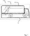
- Figure 1 represents an electric heavy-duty vehicle 1
- the electric heavy-duty vehicle 1 is a garbage truck.
- the electric heavy-duty vehicle 1 comprises an electrical system 10.
- Such an electrical system 10 comprises a vehicle network 20 and an external network 400.
- FIG 2 is a detailed view of an electric system of the electric heavy-duty vehicle of figure 1 .
- the vehicle network 20 comprises a converter unit 300 and an on-board network 200.
- the on-board network 200 comprises a battery unit 201 and one or more internal loads 202a, 202b.
- the on-board network 200 and the converter unit 300 are connected.
- the converter unit 300 is adapted for connecting a traction voltage network 100 and an on-board network 200.
- the traction voltage network 100 comprises electric motors 101, an electric storage system 102 and traction loads 103.
- the vehicle network 20 comprises a switching unit 600.
- the switching unit 600 is an electrical switch, in particular a relay, and/or a transistor, in particular a MOSFET.
- the switching unit 600 By means of the switching unit 600 a power output to the external network 400 can be controlled.
- the switching unit 600 is adapted for connecting and disconnecting the on-board network 200 and an external network 400.
- the switching unit 600 connects and disconnects the external network 400 from the on-board network 200 depending on at least one determined current information of the electrical system 10 and a determined at least one safety current value.
- Such an external network 400 may have one or more external loads 401.
- the electric system 10 comprises a master control unit 500.
- the master control unit 500 is signal-coupled with the electrical system 10, in particular the switching unit 600, the converter unit 300, and the on-board network 200.
- the master control unit 500 is adapted for controlling an electrical system 10 of an electric heavy-duty vehicle 1, in particular its switching unit 600.
- the electrical system 10 may comprise a vehicle control unit 700.
- the vehicle control unit 700 is signal-coupled with the converter unit 300, the on-board network 200, and one non-critical internal load 202a.
- the vehicle control unit 700 is adapted for controlling one or more internal loads 202, in particular one or more non-critical internal loads 202a, of the on-board network 200.
- Both, the master control unit 500 and the vehicle control unit 700 are configured to perform the steps of a method for controlling an electrical system 10 of the electric heavy-duty vehicle 1.
- Figure 3 is a first embodiment of a schematic flow diagram of the method for controlling an electrical system of figure 2 .
- the method comprises three steps.
- the method comprises the step of determining S1 at least one current information of the electrical system 10.
- the at least one current information of the electrical system 10 is a status information of the converter unit and/or a battery current value of the battery of the on-board network 200 and/or an external load current consumption value of the external network 400.
- the status information of the converter unit 300 is at least one of the following: an operation status of the converter unit 300; an actual converter output current; and/or a maximum converter current capacity value.
- the method comprises the step of determining S2 at least one safety current value.
- the at least one safety current value is a current protection value and/or a limitation value.
- the method comprises the step of controlling S3 the switching unit 600 to control the power output from the on-board network 200 to the external network 300 depending on the determined at least one current information of the electrical system 10 and the determined at least one safety current value.
- the step of controlling S3 the power output from the on-board network 200 to the external network 300 comprises closing the switching unit 600 for connecting the on-board network 200 with the external network 400.
- the step of controlling S3 the power output from the on-board network 200 to the external network 300 comprises opening the switching unit 600 for disconnecting the on-board network 200 from the external network 400.
- a discrete or continuous adjustment of the switching unit 600 for discrete or continuous adjustment of the output power may be preferred.
- the switching unit 600 is closed if the determined operation status of the converter unit 300 signals full readiness for operation, and the determined battery current value signals that the battery is connected to the on-board network 200 and under charge and the determined actual converter output current minus the determined battery current value is below a threshold of the determined maximum converter current capacity value.
- the switching unit 600 is opened if the determined operation status of the converter unit 300 does not signal readiness for operation.
- the switching unit 600 is controlled discretely or continuously to discretely or continuously control the output power if the determined operation status of the converter unit 300 signals partial readiness for operation and/or the determined battery current value signals that the battery is not connected to the on-board network 200 and/or not under charge.
- the switching unit 600 is controlled discretely or continuously to discretely or continuously control the output power if the determined operation status of the converter unit 300 signals full readiness for operation, and the determined battery current value signals that the battery is connected to the on-board network 200 and under charge and the determined actual converter output current minus the determined battery current value is above the threshold of the determined maximum converter current capacity value.
- Figure 4 is a second embodiment of a schematic flow diagram of the method for controlling an electrical system of figure 2 .
- the method comprises foursteps.
- the second embodiment of the method schematically shown in figure 4 is based on the first embodiment of the method schematically shown in figure 3 .
- the second embodiment of the method additionally comprises the step of controlling S4 the one or more non-critical internal loads 202a depending on the determined at least one current information of the electrical system.
- the step of controlling S4 the one or more non-critical internal loads 202a comprises a sub-step of connecting and/or disconnecting the one or more non-critical internal loads 202a from the on-board network 200.
- the step of controlling S4 the one or more non-critical internal loads 202a comprises a sub-step of discrete or continuous adjustment of the one or more non-critical internal loads 202a.
- the step of determining S2 at least one safety current value may comprise at least one of the four following sub-steps:
- a first sub-step is defining S20 a minimum and/or maximum safety current value.
- the second and third sub-steps are determining the at least one safety current value as maximum safety current value S21 and/or determining the at least one safety current value as minimum safety current value S22.
- the fourth sub-step is determining the at least one safety current value as a minimum S23 of the sum of the determined maximum converter current capacity value minus the determined actual converter output current plus the determined battery current value plus the external load current consumption value and the maximum safety current value.
- the at least one safety current value is determined as maximum safety current value S21 if the determined operation status of the converter unit 300 signals full readiness for operation, and the determined battery current value signals that the battery is connected to the on-board network 200 and under charge and the determined actual converter output current minus the determined battery current value is below the threshold of the determined maximum converter current capacity value.
- the at least one safety current value is determined as minimum safety current value S22 if the determined operation status of the converter unit 300 does not signal readiness for operation; and/or the determined battery current value signals that the battery is connected to the on-board network 200 and/or under discharge.
- the at least one safety current value is determined as minimum safety current value S23 of the sum of the determined maximum converter current capacity value minus the determined actual converter output current plus the determined battery current value plus the external load current consumption value and the maximum safety current value if the determined operation status of the converter unit 300 signals partial readiness for operation and/or the determined battery current value signals that the battery is not connected to the on-board network 200 and/or under discharge.
- the at least one safety current value is determined as minimum safety current value S23 of the sum of the determined maximum converter current capacity value minus the determined actual converter output current plus the determined battery current value plus the external load current consumption value and the maximum safety current value if the determined operation status of the converter unit 300 signals full readiness for operation, and the determined battery current value signals that the battery is connected to the on-board network 200 and under charge and the determined actual converter output current minus the determined battery current value is above the determined at least one safety current value.
- the power output from the on-board network 200 to the external network 300 is controlled by opening the switching unit 600, to limit as much as possible the current consumption on the on-board network (that will be supplied from batteries).
- other non-safety high power loads i.e. for example non-critical internal loads 202a - can be cut-off. This can be directly controlled from a vehicle control unit 700. This in order to ensure a safe stop of the electric vehicle 1.
- Figures 5 and 6 schematically illustrate two use cases when a severe issues M occurs with an associated reaction of the electric system 10, respectively of the method for controlling the electrical system 10 of the electric vehicle 1.
- Figure 5 refers to a first use case, schematically illustrates the maximum converter current capacity value "A”, the actual converter output current "B", the battery current value of the battery of the on-board network "C”, the safety current value “D”, the external load current consumption value of the external network "E”, and the non-critical internal load current "F” overtime if a severe issue M is detected as described above.
- the severe issue detected M is a malfunctioning converter unit 300 that is derated.
- the at least one safety current value is determined as minimum safety current value S22 as the determined operation status of the converter unit 300 signals its non-readiness for operation.
- Figure 6 refers to a second use case, schematically illustrates the maximum converter current capacity value "A”, the actual converter output current "B", the battery current value of the battery of the on-board network “F”, the safety current value “D”, the external load current consumption value of the external network "E”, and a vehicle load current (without external loads) "C” over time if a severe issue M is detected as described above.
- the severe issue detected M is a detected low voltage battery open circuit in the on-board network 200.
- the at least one safety current value is determined as minimum of the sum of the determined maximum converter current capacity value minus the determined actual converter output current plus the determined battery current value plus the external load current consumption value and the maximum safety current value as the determined battery current value signals that the battery is not connected to the on-board network 200. Further, at some time, the switching unit is controlled S3 in order to control the power output from the on-board network to the external network as the consumption value of the external network "E" would otherwise exceed the determined safety current value "D".
Priority Applications (3)
| Application Number | Priority Date | Filing Date | Title |
|---|---|---|---|
| EP21184242.2A EP4116129A1 (de) | 2021-07-07 | 2021-07-07 | Verfahren und master-steuereinheit zur steuerung eines elektrischen systems eines elektrischen fahrzeugs |
| US17/856,244 US20230010979A1 (en) | 2021-07-07 | 2022-07-01 | Method and a master control unit for controlling an electrical system of an electric vehicle |
| CN202210783221.5A CN115648940A (zh) | 2021-07-07 | 2022-07-05 | 用于控制电动车辆的电气系统的方法和主控制单元 |
Applications Claiming Priority (1)
| Application Number | Priority Date | Filing Date | Title |
|---|---|---|---|
| EP21184242.2A EP4116129A1 (de) | 2021-07-07 | 2021-07-07 | Verfahren und master-steuereinheit zur steuerung eines elektrischen systems eines elektrischen fahrzeugs |
Publications (1)
| Publication Number | Publication Date |
|---|---|
| EP4116129A1 true EP4116129A1 (de) | 2023-01-11 |
Family
ID=76829439
Family Applications (1)
| Application Number | Title | Priority Date | Filing Date |
|---|---|---|---|
| EP21184242.2A Pending EP4116129A1 (de) | 2021-07-07 | 2021-07-07 | Verfahren und master-steuereinheit zur steuerung eines elektrischen systems eines elektrischen fahrzeugs |
Country Status (3)
| Country | Link |
|---|---|
| US (1) | US20230010979A1 (de) |
| EP (1) | EP4116129A1 (de) |
| CN (1) | CN115648940A (de) |
Families Citing this family (1)
| Publication number | Priority date | Publication date | Assignee | Title |
|---|---|---|---|---|
| CN111655546A (zh) * | 2018-01-25 | 2020-09-11 | 沃尔沃建筑设备公司 | 均衡器过载管理 |
Citations (7)
| Publication number | Priority date | Publication date | Assignee | Title |
|---|---|---|---|---|
| US6580180B2 (en) | 2000-04-13 | 2003-06-17 | Yazaki Corporation | Power supply apparatus for vehicle |
| US20120306263A1 (en) | 2011-05-30 | 2012-12-06 | Hitachi Automotive Systems, Ltd. | Control Device for Electrically Powered Vehicle |
| KR101439060B1 (ko) | 2013-10-29 | 2014-09-05 | 현대자동차주식회사 | 차량의 배터리 제어 장치 및 제어 방법 |
| EP2823987A1 (de) * | 2012-03-07 | 2015-01-14 | Toyota Jidosha Kabushiki Kaisha | Elektrofahrzeug und steuerverfahren dafür |
| WO2019238203A1 (en) | 2018-06-11 | 2019-12-19 | Volvo Truck Corporation | Dc/dc converter overload management in vehicle electrical systems |
| US20200108819A1 (en) * | 2018-10-09 | 2020-04-09 | Ford Global Technologies, Llc | Hybrid vehicle with electrical power outlet |
| WO2021004639A1 (en) * | 2019-07-11 | 2021-01-14 | Volvo Truck Corporation | A control unit for an electric power transmission system |
-
2021
- 2021-07-07 EP EP21184242.2A patent/EP4116129A1/de active Pending
-
2022
- 2022-07-01 US US17/856,244 patent/US20230010979A1/en active Pending
- 2022-07-05 CN CN202210783221.5A patent/CN115648940A/zh active Pending
Patent Citations (7)
| Publication number | Priority date | Publication date | Assignee | Title |
|---|---|---|---|---|
| US6580180B2 (en) | 2000-04-13 | 2003-06-17 | Yazaki Corporation | Power supply apparatus for vehicle |
| US20120306263A1 (en) | 2011-05-30 | 2012-12-06 | Hitachi Automotive Systems, Ltd. | Control Device for Electrically Powered Vehicle |
| EP2823987A1 (de) * | 2012-03-07 | 2015-01-14 | Toyota Jidosha Kabushiki Kaisha | Elektrofahrzeug und steuerverfahren dafür |
| KR101439060B1 (ko) | 2013-10-29 | 2014-09-05 | 현대자동차주식회사 | 차량의 배터리 제어 장치 및 제어 방법 |
| WO2019238203A1 (en) | 2018-06-11 | 2019-12-19 | Volvo Truck Corporation | Dc/dc converter overload management in vehicle electrical systems |
| US20200108819A1 (en) * | 2018-10-09 | 2020-04-09 | Ford Global Technologies, Llc | Hybrid vehicle with electrical power outlet |
| WO2021004639A1 (en) * | 2019-07-11 | 2021-01-14 | Volvo Truck Corporation | A control unit for an electric power transmission system |
Also Published As
| Publication number | Publication date |
|---|---|
| CN115648940A (zh) | 2023-01-31 |
| US20230010979A1 (en) | 2023-01-12 |
Similar Documents
| Publication | Publication Date | Title |
|---|---|---|
| EP2476574B1 (de) | Stromversorgungssystem für ein fahrzeug und steuerverfahren dafür | |
| US10800360B2 (en) | Electric power system of vehicle with quick discharge of a high-voltage condenser | |
| JP5525731B2 (ja) | 電気またはハイブリッド自動車用のエネルギー蓄積システム | |
| US7923866B2 (en) | Power supply system and vehicle including the same, and method of controlling the same | |
| JP5171578B2 (ja) | 車両用バッテリー制御装置 | |
| US11458844B2 (en) | Power supply system for vehicle | |
| CN109941106B (zh) | 电动车辆的电源系统 | |
| US20130030621A1 (en) | Discharge technique for residual high voltage in hybrid vehicle and method thereof | |
| CN110549890B (zh) | Dc/dc转换单元 | |
| EP3321119B1 (de) | Fahrzeugversorgungssystem | |
| CN104136262A (zh) | 电动车 | |
| EP2647521A1 (de) | Steuervorrichtung für ein elektrofahrzeug | |
| US10787136B2 (en) | Electric power system for controlling pre-charge of vehicle | |
| DE102010061618A1 (de) | Steuerung für einen Hybrid-Hochspannungs-Isolationsschutz | |
| CN110143204A (zh) | 一种城轨车辆电池应急牵引控制方法及其控制系统 | |
| WO2015140618A1 (en) | Charging system mouted on vehicle | |
| JP2010213503A (ja) | 電力供給装置および方法 | |
| US20230010979A1 (en) | Method and a master control unit for controlling an electrical system of an electric vehicle | |
| CN112046288A (zh) | 电源系统 | |
| JP2018121397A (ja) | 電動自動車 | |
| JP2005229706A (ja) | 車両の制御装置 | |
| CN217396456U (zh) | 车辆供电系统 | |
| CN214607388U (zh) | 电路系统及取消低压蓄电池的车辆 | |
| US20240120851A1 (en) | Electrified vehicle with active discharge of high-voltage bus | |
| CN220809202U (zh) | 电池管理系统及电动汽车 |
Legal Events
| Date | Code | Title | Description |
|---|---|---|---|
| PUAI | Public reference made under article 153(3) epc to a published international application that has entered the european phase |
Free format text: ORIGINAL CODE: 0009012 |
|
| STAA | Information on the status of an ep patent application or granted ep patent |
Free format text: STATUS: THE APPLICATION HAS BEEN PUBLISHED |
|
| AK | Designated contracting states |
Kind code of ref document: A1 Designated state(s): AL AT BE BG CH CY CZ DE DK EE ES FI FR GB GR HR HU IE IS IT LI LT LU LV MC MK MT NL NO PL PT RO RS SE SI SK SM TR |
|
| STAA | Information on the status of an ep patent application or granted ep patent |
Free format text: STATUS: REQUEST FOR EXAMINATION WAS MADE |
|
| 17P | Request for examination filed |
Effective date: 20230201 |
|
| RBV | Designated contracting states (corrected) |
Designated state(s): AL AT BE BG CH CY CZ DE DK EE ES FI FR GB GR HR HU IE IS IT LI LT LU LV MC MK MT NL NO PL PT RO RS SE SI SK SM TR |