EP4115989B1 - Kleberauftragsvorrichtung - Google Patents
Kleberauftragsvorrichtung Download PDFInfo
- Publication number
- EP4115989B1 EP4115989B1 EP21184860.1A EP21184860A EP4115989B1 EP 4115989 B1 EP4115989 B1 EP 4115989B1 EP 21184860 A EP21184860 A EP 21184860A EP 4115989 B1 EP4115989 B1 EP 4115989B1
- Authority
- EP
- European Patent Office
- Prior art keywords
- slot
- nozzle
- dosing
- adhesive application
- application apparatus
- Prior art date
- Legal status (The legal status is an assumption and is not a legal conclusion. Google has not performed a legal analysis and makes no representation as to the accuracy of the status listed.)
- Active
Links
Images



Classifications
-
- B—PERFORMING OPERATIONS; TRANSPORTING
- B05—SPRAYING OR ATOMISING IN GENERAL; APPLYING FLUENT MATERIALS TO SURFACES, IN GENERAL
- B05C—APPARATUS FOR APPLYING FLUENT MATERIALS TO SURFACES, IN GENERAL
- B05C5/00—Apparatus in which liquid or other fluent material is projected, poured or allowed to flow on to the surface of the work
- B05C5/02—Apparatus in which liquid or other fluent material is projected, poured or allowed to flow on to the surface of the work the liquid or other fluent material being discharged through an outlet orifice by pressure, e.g. from an outlet device in contact or almost in contact, with the work
- B05C5/0204—Apparatus in which liquid or other fluent material is projected, poured or allowed to flow on to the surface of the work the liquid or other fluent material being discharged through an outlet orifice by pressure, e.g. from an outlet device in contact or almost in contact, with the work for applying liquid or other fluent material to the edges of essentially flat articles
-
- B—PERFORMING OPERATIONS; TRANSPORTING
- B05—SPRAYING OR ATOMISING IN GENERAL; APPLYING FLUENT MATERIALS TO SURFACES, IN GENERAL
- B05C—APPARATUS FOR APPLYING FLUENT MATERIALS TO SURFACES, IN GENERAL
- B05C5/00—Apparatus in which liquid or other fluent material is projected, poured or allowed to flow on to the surface of the work
- B05C5/02—Apparatus in which liquid or other fluent material is projected, poured or allowed to flow on to the surface of the work the liquid or other fluent material being discharged through an outlet orifice by pressure, e.g. from an outlet device in contact or almost in contact, with the work
- B05C5/0254—Coating heads with slot-shaped outlet
- B05C5/0258—Coating heads with slot-shaped outlet flow controlled, e.g. by a valve
-
- B—PERFORMING OPERATIONS; TRANSPORTING
- B05—SPRAYING OR ATOMISING IN GENERAL; APPLYING FLUENT MATERIALS TO SURFACES, IN GENERAL
- B05C—APPARATUS FOR APPLYING FLUENT MATERIALS TO SURFACES, IN GENERAL
- B05C5/00—Apparatus in which liquid or other fluent material is projected, poured or allowed to flow on to the surface of the work
- B05C5/02—Apparatus in which liquid or other fluent material is projected, poured or allowed to flow on to the surface of the work the liquid or other fluent material being discharged through an outlet orifice by pressure, e.g. from an outlet device in contact or almost in contact, with the work
- B05C5/0254—Coating heads with slot-shaped outlet
- B05C5/0266—Coating heads with slot-shaped outlet adjustable in length, e.g. for coating webs of different width
-
- B—PERFORMING OPERATIONS; TRANSPORTING
- B27—WORKING OR PRESERVING WOOD OR SIMILAR MATERIAL; NAILING OR STAPLING MACHINES IN GENERAL
- B27D—WORKING VENEER OR PLYWOOD
- B27D5/00—Other working of veneer or plywood specially adapted to veneer or plywood
- B27D5/003—Other working of veneer or plywood specially adapted to veneer or plywood securing a veneer strip to a panel edge
-
- B—PERFORMING OPERATIONS; TRANSPORTING
- B27—WORKING OR PRESERVING WOOD OR SIMILAR MATERIAL; NAILING OR STAPLING MACHINES IN GENERAL
- B27G—ACCESSORY MACHINES OR APPARATUS FOR WORKING WOOD OR SIMILAR MATERIALS; TOOLS FOR WORKING WOOD OR SIMILAR MATERIALS; SAFETY DEVICES FOR WOOD WORKING MACHINES OR TOOLS
- B27G11/00—Applying adhesives or glue to surfaces of wood to be joined
-
- B—PERFORMING OPERATIONS; TRANSPORTING
- B05—SPRAYING OR ATOMISING IN GENERAL; APPLYING FLUENT MATERIALS TO SURFACES, IN GENERAL
- B05C—APPARATUS FOR APPLYING FLUENT MATERIALS TO SURFACES, IN GENERAL
- B05C5/00—Apparatus in which liquid or other fluent material is projected, poured or allowed to flow on to the surface of the work
- B05C5/02—Apparatus in which liquid or other fluent material is projected, poured or allowed to flow on to the surface of the work the liquid or other fluent material being discharged through an outlet orifice by pressure, e.g. from an outlet device in contact or almost in contact, with the work
- B05C5/0225—Apparatus in which liquid or other fluent material is projected, poured or allowed to flow on to the surface of the work the liquid or other fluent material being discharged through an outlet orifice by pressure, e.g. from an outlet device in contact or almost in contact, with the work characterised by flow controlling means, e.g. valves, located proximate the outlet
- B05C5/0229—Apparatus in which liquid or other fluent material is projected, poured or allowed to flow on to the surface of the work the liquid or other fluent material being discharged through an outlet orifice by pressure, e.g. from an outlet device in contact or almost in contact, with the work characterised by flow controlling means, e.g. valves, located proximate the outlet the valve being a gate valve or a sliding valve
- B05C5/0233—Apparatus in which liquid or other fluent material is projected, poured or allowed to flow on to the surface of the work the liquid or other fluent material being discharged through an outlet orifice by pressure, e.g. from an outlet device in contact or almost in contact, with the work characterised by flow controlling means, e.g. valves, located proximate the outlet the valve being a gate valve or a sliding valve rotating valve, e.g. rotating perforated cylinder
Definitions
- the invention relates to an adhesive application device for an edge banding machine for applying a molten adhesive to a longitudinal side of a workpiece moved in a feed direction, comprising a nozzle body which has a nozzle channel with a nozzle slot extending in the longitudinal direction of the nozzle channel for dispensing the adhesive onto the longitudinal side of the workpiece, and further comprising a dosing sleeve which is rotatable in the nozzle channel about its longitudinal axis and which has a dosing slot which can be positioned in alignment with the nozzle slot and is aligned in the longitudinal direction of the nozzle channel.
- Such an adhesive application device is known from EP 2 308 605 A1 It is used in edge banding machines, with which a glued edge, often also referred to as a "edge band", can be fed to a long side of the workpiece running parallel to the feed direction of the workpiece and glued to the workpiece. The workpiece with the edge band is then usually fed to a post-processing stage in order to achieve a continuous transition between the top and bottom sides of the workpiece and the edge band.
- a post-processing stage in order to achieve a continuous transition between the top and bottom sides of the workpiece and the edge band.
- the adhesive application device has a nozzle body which has a nozzle channel with a nozzle slot extending in the longitudinal direction of the nozzle channel.
- a dosing sleeve is arranged in the nozzle channel, which can be rotated about the longitudinal axis of the nozzle channel and has a dosing slot which can be positioned in alignment with the nozzle slot and is aligned in the longitudinal direction of the nozzle channel.
- the molten adhesive can be fed to the dosing sleeve and applied from there to the long side of the workpiece via the dosing slot and the nozzle slot aligned in alignment with the dosing slot.
- the dosing sleeve By rotating the dosing sleeve about the longitudinal axis of the nozzle channel, the dosing sleeve can be pivoted back and forth between an open position, in which the dosing slot is aligned with the nozzle slot, and a closed position, in which the dosing slot is arranged offset from the nozzle slot in the circumferential direction of the nozzle channel, in order to control the application of the adhesive.
- the dosing sleeve forms a lower end section of a dosing rod that passes through the nozzle channel.
- the dosing rod can be rotated about the longitudinal axis of the nozzle channel and displaced in the longitudinal direction of the nozzle channel.
- the dosing sleeve can be positioned such that the dosing slot is aligned with the nozzle slot, as explained above.
- a limiting member is rotatably held on the dosing rod, which dips into the nozzle slot and limits the opening area of the nozzle slot in the vertical direction upwards.
- the limiting member By displacing the dosing rod in the longitudinal direction of the nozzle channel, the limiting member can be positioned in the nozzle slot such that a lower end surface of the limiting member can be positioned at the level of an upper longitudinal edge of the workpiece. This can ensure that molten adhesive cannot reach the top of the workpiece and impair it.
- the object of the present invention is therefore to further develop an adhesive application device of the type mentioned at the outset in such a way that modern adhesives can be processed even more reliably.
- an adjusting piston is mounted in the dosing sleeve so as to be displaceable in the longitudinal direction of the nozzle channel, with a dosing slot limiting part on the adjusting piston which dips into the dosing slot and is The longitudinal axis of the nozzle channel is rotatably mounted, which limits the opening area of the dosing slot in the vertical direction upwards.
- the dosing sleeve with the aid of which the application of adhesive to the nozzle slot can be controlled, can be rotated about the longitudinal axis of the nozzle channel, but it is not necessarily displaceable in the longitudinal direction of the nozzle channel.
- the actuating piston, on which the dosing slot limiting part is held, which limits the opening area of the dosing slot upwards, can be moved in the longitudinal direction of the nozzle channel, but it is not necessarily rotatable about the longitudinal axis of the nozzle channel.
- the application of adhesive to the long side of the workpiece is controlled with the aid of the dosing sleeve, which can be rotated but not necessarily displaced, and the opening area of the dosing slot is controlled with the aid of the actuating piston, which can be moved but not necessarily rotated and on which the dosing slot limiting part is held.
- the opening area of the dosing slot is limited in the vertical direction upwards by means of the dosing slot limiting part.
- the dosing slot limiting part that dips into the dosing slot follows the rotational movement of the dosing sleeve.
- the dosing slot limiting part is mounted on the actuating piston so that it can rotate about the longitudinal axis of the nozzle channel.
- the dosing slot limiting part is positioned in the vertical direction with the aid of the actuating piston, which can be moved back and forth in the longitudinal direction of the nozzle channel for this purpose.
- the dosing sleeve is mounted non-adjustably in the longitudinal direction of the nozzle channel.
- the dosing slot limiting part has a first sliding piece and a second sliding piece, wherein the first sliding piece dips into a circumferential annular groove of the actuating piston and slides against opposing groove walls of the annular groove, and wherein the second sliding piece dips into the dosing slot and slides against opposing slot walls of the dosing slot.
- the first sliding piece is used for the rotatable mounting of the dosing slot limiting part on the actuating piston
- the second sliding piece is used to limit the opening area of the dosing slot in a vertical upward direction.
- the second sliding piece dips into the dosing slot follows the dosing sleeve and the first sliding piece slides along the groove walls of the annular groove of the actuating piston.
- the first sliding piece dips into the annular groove follows the actuating piston and the second sliding piece slides along the slot walls of the dosing slot.
- the first sliding piece extends in the circumferential direction over a partial area of the annular groove.
- the second sliding piece extends in the axial direction preferably up to the level of a lower end face of the actuating piston.
- the actuating piston is held on a piston rod which is adjustably mounted in the dosing sleeve in the longitudinal direction of the nozzle channel.
- the actuating piston can be easily positioned in the vertical direction in the dosing sleeve via the piston rod.
- the piston rod is adjustable manually, by electric motor or pneumatically.
- the piston rod is adjustable via program control.
- the piston rod is adjustable in the longitudinal direction of the nozzle channel by means of an actuator, in particular a servomotor.
- the piston rod can be coupled to the actuator, for example, via gear elements, in particular via a spindle drive.
- the adhesive application device has, in addition to the metering slot limiting part, a nozzle slot limiting part which dips into the nozzle slot, wherein the opening area of the nozzle slot can be limited in the vertical upward direction by means of the nozzle slot limiting part.
- the opening area of the metering slot is limited in the vertical upward direction by means of the metering slot limiting part, and the opening area of the nozzle slot in the vertical upward direction is limited by means of the nozzle slot limiting part.
- the nozzle slot limiting part is coupled to the metering slot limiting part.
- the coupling allows the vertical position of the metering slot limiting part to be adapted to the vertical position of the nozzle slot limiting part in a structurally simple manner.
- the nozzle slot limiting part is coupled to a sensing device, whereby an upper longitudinal edge of the workpiece can be detected with or without contact by means of the sensing device, which limits the longitudinal side of the workpiece on the upper side to which the adhesive is to be applied.
- the coupling of the nozzle slot limiting part to the sensing device allows the nozzle slot limiting part to be positioned depending on the position of the upper longitudinal edge of the workpiece and thus depending on the thickness of the workpiece. In particular, this makes it easy to position a lower end surface of the nozzle slot limiting part at the level of the upper longitudinal edge of the workpiece.
- the sensing device preferably has a sensing element which can be placed on the upper longitudinal edge of the workpiece, wherein the upper longitudinal edge delimits the upper side of the longitudinal side of the workpiece to which the adhesive is to be applied.
- the nozzle slot limiting part is rigidly connected to the probe element.
- the nozzle slot limiting part is designed as a projection of the probe element that extends into the nozzle slot.
- the projection can slide against two opposite slot walls of the nozzle slot.
- the sensing device is held on a guide rod which is mechanically connected to the piston rod.
- the probe device is spring-loaded towards the top of the workpiece.
- a compression spring is clamped between the probe device and the guide rod, which applies a spring-elastic preload to the probe device in the direction of the top side of the workpiece.
- the nozzle body has a flushing opening arranged in the circumferential direction of the nozzle channel offset from the nozzle slot, which opens into a flushing channel, wherein the dosing sleeve can be rotated back and forth about the longitudinal axis of the nozzle channel between an adhesive application position in which the dosing slot is aligned with the nozzle slot, a flushing position in which the dosing slot is aligned with the flushing opening, and a closed position in which the dosing slot is covered by the wall of the nozzle channel.
- the dosing sleeve can be rotated about the Longitudinal axis of the nozzle channel can be rotated into a flushing position in which the dosing slot is aligned with the nozzle slot.
- the dosing sleeve can be rotated about the longitudinal axis of the nozzle channel into a flushing position in which the dosing slot is aligned with a flushing opening that opens into a flushing channel.
- Molten adhesive can be fed to a collecting container via the flushing channel for cleaning purposes.
- the dosing sleeve can be rotated about the longitudinal axis of the nozzle channel into a closed position in which the dosing slot is covered by the wall of the nozzle channel.
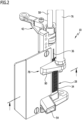
- the drawing schematically shows an adhesive application device 10 for an edge banding machine that is known per se and is therefore not shown in the drawing to provide a better overview.
- the edge banding machine has a machine upper part and a machine lower part in the usual way.
- the machine lower part comprises a frame and various processing units such as saws and milling machines.
- the machine upper part is held so that it can be adjusted in the vertical direction relative to the machine lower part.
- Transport links for example conveyor chains, are mounted on the machine upper part and the machine lower part, with the help of which a workpiece 12 can be moved in a feed direction 14.
- the workpiece 12 has various sides, namely a front side 16, a back side 18, an upper side 20, a lower side 22, a first longitudinal side 24 and a second longitudinal side 26.
- a molten adhesive can be applied to the first longitudinal side 24 by means of the adhesive application device 10.
- a glued edge can then be glued to the first long side using the edge banding machine.
- the adhesive application device 10 comprises a nozzle body 28 which has a nozzle channel 30 extending in the vertical direction.
- a supply line for molten adhesive which is known per se and is therefore not shown in the drawing for the sake of clarity, can be connected to a lower end region 32 of the nozzle channel 30.
- the nozzle body 28 has a workpiece contact side 34 along which the workpiece 12 can slide with its first longitudinal side 24. In the region of the workpiece contact side 34, the nozzle body 28 has a nozzle slot 36 extending in the longitudinal direction of the nozzle channel 30.
- a dosing sleeve 38 is mounted so that it can rotate about the longitudinal axis 40 of the nozzle channel 30 but cannot move in the axial direction.
- the dosing sleeve 38 protrudes vertically upwards from the nozzle channel 30 and is connected in this protruding area in a rotationally fixed manner to a rotating arm 42, with the aid of which the dosing sleeve 38 can be rotated about the longitudinal axis 40.
- the dosing sleeve 38 has a radially outwardly projecting flange 44 in its section protruding from the nozzle channel 30, which is positioned between a stationary first holding element 46 and a stationary second holding element 48. A movement of the dosing sleeve 38 in the longitudinal direction of the nozzle channel 30 is therefore not possible.
- the rotary arm 42 is coupled to a rotary drive which is known per se and is therefore not shown in the drawing for the sake of clarity.
- a rotary drive which is known per se and is therefore not shown in the drawing for the sake of clarity.
- This can be, for example, an electric drive or a pneumatic drive.
- the dosing sleeve 38 has a dosing slot 50 aligned in the longitudinal direction of the nozzle channel 30, which can be moved by means of the rotary arm 42 between a Figures 3 and 4 illustrated adhesive application position, one in Figure 5 shown flushing position and one in Figure 6 shown closed position can be rotated back and forth about the longitudinal axis 40 of the nozzle channel 30.
- the metering slot 50 is aligned with the nozzle slot 36, so that molten adhesive can be applied to the first longitudinal side 24 of the workpiece 12 via the nozzle channel 30, the metering sleeve 38, the metering slot 50 and the nozzle slot 36.
- the rinsing position is arranged offset in the circumferential direction of the metering sleeve 38 from the adhesive application position.
- the metering slot 50 is aligned with a rinsing opening 52 of the nozzle body 28. This is particularly evident from Figure 5 clearly.
- molten adhesive can be fed via the flushing opening 52 to a flushing channel 54 of the nozzle body 28 and discharged via the flushing channel 54 to a collecting container not shown in the drawing. This is explained in more detail below.
- a closed position is arranged in which the metering slot 50 is covered by the wall of the nozzle channel 30 and is thus closed.
- An adjusting piston 56 is mounted in the dosing sleeve 38 so that it can move in the longitudinal direction of the nozzle channel 30.
- the adjusting piston 56 is detachably held on a piston rod 58.
- the adjusting piston 56 is screwed to the piston rod 58.
- the piston rod 58 protrudes from the top of the dosing sleeve 38 and is mounted in the dosing sleeve 38 so that it can move axially.
- the actuating piston 56 has an annular groove 60 running around the circumference.
- a metering slot limiting part 62 is mounted in the annular groove 60 so as to be rotatable relative to the actuating piston 56 about the longitudinal axis 40 of the nozzle channel 30.
- the metering slot limiting part 62 has a first sliding piece 64 which dips into the annular groove 60 and slides against opposing groove walls of the annular groove 60.
- a second sliding piece 66 of the metering slot limiting part 62 adjoins the first sliding piece 64 outside the annular groove 60. The second sliding piece 66 dips into the metering slot 50 and slides against two opposing slot walls of the metering slot 50.
- the second sliding piece 66 has a lower end surface 68 facing the lower end region 32 of the nozzle channel 30.
- the lower end surface 68 is arranged at the level of a lower end face 70 of the actuating piston 56 facing away from the piston rod 58.
- the lower end surface 68 delimits an opening area 72 of the dosing slot 50 in the vertical upward direction. If the dosing sleeve 38 is rotated about the longitudinal axis 40, the dosing slot limiting part 62 is carried along by the dosing sleeve 38, the dosing slot limiting part 62 being rotated about the longitudinal axis 40 relative to the actuating piston 56.
- the piston rod 58 is rigidly connected at its end section protruding from the dosing sleeve 38 via a mechanical coupling device 74 to a guide rod 76 which is aligned parallel to the piston rod 58.
- the guide rod 76 At its lower end area facing away from the coupling device 74, the guide rod 76 carries a feeler device 78, with the aid of which an upper Longitudinal edge 92 of the workpiece 12 can be scanned.
- the upper longitudinal edge 92 limits the first longitudinal side 24 at the top.
- the scanning device 78 has a scanning element 80 which can be slidably placed on the upper longitudinal edge 92.
- the scanning element 80 is fixed to a holding pin 82 which is elastically pre-tensioned by means of a compression spring 84 in the direction of the upper side 20 of the workpiece 12.
- the compression spring 84 is arranged between the guide rod 76 and the scanning device 78.
- the probe element 80 has a projection 86 which, starting from the workpiece contact side 34 of the nozzle body 28, dips into the nozzle slot 36, sliding against two opposing slot walls of the nozzle slot 36.
- the projection 86 forms a nozzle slot limiting part 88 of the adhesive application device 10, which limits an opening area 90 of the nozzle slot 36 in the vertical direction upwards.
- the nozzle slot limiting part 88 is mechanically coupled to the metering slot limiting part 62 via the sensing device 78, the compression spring 84, the guide rod 76, the coupling device 74, the piston rod 58 and the actuating piston 56.
- the vertical position of the piston rod 58 can be specified according to the thickness of the workpiece 12 by means of an actuator known per se and therefore not shown in the drawing for the sake of clarity, for example an electric or pneumatic actuator.
- This also makes it possible to specify the vertical position of the metering slot limiting part 62 and the nozzle slot limiting part 88, whereby the exact position of the nozzle slot limiting part 88 can be adapted to the upper longitudinal edge 92 by means of the elastic preload (compression spring 84) of the probe element 80, which slides against the upper longitudinal edge 92 of the workpiece 12.
- the spring-elastic preload makes it possible to compensate for minor fluctuations in the thickness of the workpiece 12.
- the dosing sleeve 38 can be rotated into its adhesive application position so that the dosing slot 50 is aligned with the nozzle slot 36. If the application of molten adhesive is to be stopped, the dosing sleeve 38 can be rotated into its closed position in which the dosing slot is offset from the nozzle slot 36 by an angle of rotation of, for example, 45° and is covered by the wall of the nozzle channel 30.
- the dosing sleeve 38 can be pivoted in the same direction of rotation by a further angle of rotation of, for example, 45° into its rinsing position in which the dosing slot 50 is aligned with the rinsing opening 52 so that molten adhesive can pass through the dosing slot 50 and the rinsing opening 52 into the rinsing channel 54 and can be guided from there to a collecting container.
Landscapes
- Life Sciences & Earth Sciences (AREA)
- Engineering & Computer Science (AREA)
- Mechanical Engineering (AREA)
- Wood Science & Technology (AREA)
- Forests & Forestry (AREA)
- Coating Apparatus (AREA)
Description
- Die Erfindung betrifft eine Kleberauftragsvorrichtung für eine Kantenanleimmaschine zum Auftragen eines schmelzflüssigen Klebers auf eine Längsseite eines in einer Vorschubrichtung bewegten Werkstücks, umfassend einen Düsenkörper, der einen Düsenkanal mit einem sich in Längsrichtung des Düsenkanals erstreckenden Düsenschlitz zum Ausgeben des Klebers auf die Längsseite des Werkstücks aufweist, und weiter umfassend eine im Düsenkanal um dessen Längsachse drehbare Dosierhülse, die einen fluchtend zum Düsenschlitz positionierbaren, in Längsrichtung des Düsenkanals ausgerichteten Dosierschlitz aufweist.
- Eine derartige Kleberauftragsvorrichtung ist aus der
EP 2 308 605 A1 bekannt. Sie kommt bei Kantenanleimmaschinen zum Einsatz, mit denen eine Anleimkante, die häufig auch als "Umleimer" bezeichnet wird, einer parallel zur Vorschubrichtung des Werkstücks verlaufenden Längsseite des Werkstücks zugeführt und mit dem Werkstück verklebt werden kann. Anschließend wird das Werkstück mit dem Umleimer üblicherweise einer Nachbearbeitung zugeführt, um einen kontinuierlichen Übergang zwischen den Ober- und Unterseiten des Werkstücks und dem Umleimer zu erzielen. In den DokumentenUS 4418640 ,US2009/007845 ,US 2002/053406 undEP 0 897 781 werden weitere ähnliche Klebstoffabgabevorrichtungen beschrieben. - Zum Auftragen des Klebers auf die Längsseite des Werkstücks weist die Kleberauftragsvorrichtung einen Düsenkörper auf, der einen Düsenkanal mit einem sich in Längsrichtung des Düsenkanals erstreckenden Düsenschlitz aufweist. Im Düsenkanal ist eine Dosierhülse angeordnet, die um die Längsachse des Düsenkanals drehbar ist und einen fluchtend zum Düsenschlitz positionierbaren, in Längsrichtung des Düsenkanals ausgerichteten Dosierschlitz aufweist. Der schmelzflüssige Kleber kann der Dosierhülse zugeführt und von dieser über den Dosierschlitz und den fluchtend zum Dosierschlitz ausgerichteten Düsenschlitz auf die Längsseite des Werkstücks aufgetragen werden. Durch Drehen der Dosierhülse um die Längsachse des Düsenkanals kann die Dosierhülse zwischen einer Offenstellung, in der der Dosierschlitz mit dem Düsenschlitz fluchtet, und einer Schließstellung, in der der Dosierschlitz in Umfangsrichtung des Düsenkanals versetzt zum Düsenschlitz angeordnet ist, hin und her geschwenkt werden, um dadurch das Auftragen des Klebers zu steuern.
- Bei der aus der
EP 2 308 605 A1 bekannten Kleberauftragsvorrichtung bildet die Dosierhülse einen unteren Endabschnitt eines Dosierstabs aus, der den Düsenkanal durchgreift. Der Dosierstab ist um die Längsachse des Düsenkanals drehbar und in Längsrichtung des Düsenkanals verschiebbar. Durch Drehen des Dosierstabs kann die Dosierhülse derart positioniert werden, dass der Dosierschlitz mit dem Düsenschlitz fluchtet, wie voranstehend erläutert. Am Dosierstab ist ein Begrenzungsglied drehbar gehalten, das in den Düsenschlitz eintaucht und den Öffnungsbereich des Düsenschlitzes in vertikaler Richtung nach oben begrenzt. Durch Verschieben des Dosierstabs in Längsrichtung des Düsenkanals kann das Begrenzungsglied im Düsenschlitz derart positioniert werden, dass eine untere Endfläche des Begrenzungsglieds in Höhe einer oberen Längskante des Werkstücks positioniert werden kann. Dadurch kann sichergestellt werden, dass schmelzflüssiger Kleber nicht zur Oberseite des Werkstücks gelangen und diese beeinträchtigen kann. - Die aus der
EP 2 308 605 A1 bekannte Kleberauftragsvorrichtung hat sich in der Praxis bewährt. Allerdings wäre es wünschenswert, die Prozesssicherheit bei der Verarbeitung moderner Kleber noch zu erhöhen. - Aufgabe der vorliegenden Erfindung ist es daher, eine Kleberauftragsvorrichtung der eingangs genannten Art derart weiterzubilden, dass moderne Kleber noch prozesssicherer verarbeitbar sind.
- Diese Aufgabe wird bei einer Kleberauftragsvorrichtung der gattungsgemäßen Art erfindungsgemäß dadurch gelöst, dass in der Dosierhülse ein Stellkolben in Längsrichtung des Düsenkanals verschiebar gelagert ist, wobei am Stellkolben ein in den Dosierschlitz eintauchendes Dosierschlitzbegrenzungsteil um die Längsachse des Düsenkanals drehbar gelagert ist, das den Öffnungsbereich des Dosierschlitzes in vertikaler Richtung nach oben begrenzt.
- Gemäß der Erfindung ist die Dosierhülse, mit deren Hilfe das Auftragen von Kleber am Düsenschlitz gesteuert werden kann, zwar um die Längsachse des Düsenkanals drehbar, sie ist aber nicht zwingend in Längsrichtung des Düsenkanals verschiebbar. Der Stellkolben, an dem das Dosierschlitzbegrenzungsteil gehalten ist, welches den Öffnungsbereich des Dosierschlitzes nach oben begrenzt, ist zwar in Längsrichtung des Düsenkanals verschiebbar, er ist aber nicht zwingend um die Längsachse des Düsenkanals drehbar. Bei der erfindungsgemäßen Kleberauftragsvorrichtung erfolgt die Steuerung des Auftragens von Kleber auf die Längsseite des Werkstücks mit Hilfe der zwar drehbaren, nicht aber zwingend verschiebbaren Dosierhülse, und die Steuerung des Öffnungsbereichs des Dosierschlitzes erfolgt mit Hilfe des zwar verschiebbaren, nicht aber zwingend drehbaren Stellkolbens, an dem das Dosierschlitzbegrenzungsteil gehalten ist. Dies erlaubt es, moderne Kleber noch prozesssicherer zu verarbeiten.
- Bei der erfindungsgemäßen Kleberauftragsvorrichtung wird der Öffnungsbereich des Dosierschlitzes in vertikaler Richtung nach oben mittels des Dosierschlitzbegrenzungsteils begrenzt. Bei einer Drehbewegung der Dosierhülse um die Längsachse des Düsenkanals folgt das in den Dosierschlitz eintauchende Dosierschlitzbegrenzungsteil der Drehbewegung der Dosierhülse. Zu diesem Zweck ist das Dosierschlitzbegrenzungsteil am Stellkolben um die Längsachse des Düsenkanals drehbar gelagert. Die Positionierung des Dosierschlitzbegrenzungsteils in vertikaler Richtung erfolgt mit Hilfe des Stellkolbens, der zu diesem Zweck in Längsrichtung des Düsenkanals hin und her bewegt werden kann.
- Bei einer bevorzugten Ausgestaltung der erfindungsgemäßen Kleberauftragsvorrichtung ist die Dosierhülse in Längsrichtung des Düsenkanals unverstellbar gelagert.
- Von Vorteil ist es, wenn das Dosierschlitzbegrenzungsteil ein erstes Gleitstück und ein zweites Gleitstück aufweist, wobei das erste Gleitstück in eine in Umfangsrichtung umlaufende Ringnut des Stellkolbens eintaucht und an einander gegenüberliegenden Nutwänden der Ringnut gleitend anliegt, und wobei das zweite Gleitstück in den Dosierschlitz eintaucht und an einander gegenüberliegenden Schlitzwänden des Dosierschlitzes gleitend anliegt. Das erste Gleitstück dient der drehbaren Lagerung des Dosierschlitzbegrenzungsteils am Stellkolben, und das zweite Gleitstück dient der Begrenzung des Öffnungsbereichs des Dosierschlitzes in vertikaler Richtung nach oben. Bei einer Drehbewegung der Dosierhülse folgt das in den Dosierschlitz eintauchende zweite Gleitstück der Dosierhülse und das erste Gleitstück gleitet an den Nutwänden der Ringnut des Stellkolbens entlang. Bei einer Axialbewegung des Stellkolbens folgt das in die Ringnut eintauchende erste Gleitstück dem Stellkolben und das zweite Gleitstück gleitet an den Schlitzwänden des Dosierschlitzes entlang.
- Bevorzugt erstreckt sich das erste Gleitstück in Umfangsrichtung über einen Teilbereich der Ringnut.
- Das zweite Gleitstück erstreckt sich in axialer Richtung vorzugsweise bis in Höhe einer unteren Stirnseite des Stellkolbens.
- Der Stellkolben ist bei einer vorteilhaften Ausgestaltung der Erfindung an einer Kolbenstange gehalten, die in der Dosierhülse in Längsrichtung des Düsenkanals verstellbar gelagert ist. Über die Kolbenstange kann der Stellkolben auf einfache Weise in vertikaler Richtung in der Dosierhülse positioniert werden.
- Die Kolbenstange ist bei einer bevorzugten Ausgestaltung der Erfindung manuell, elektromotorisch oder pneumatisch verstellbar.
- Bevorzugt ist die Kolbenstange programmgesteuert verstellbar.
- Es kann vorgesehen sein, dass die Kolbenstange mittels eines Stellglieds, insbesondere eines Stellmotors, in Längsrichtung des Düsenkanals verstellbar ist.
- Die Kopplung der Kolbenstange mit dem Stellglied kann beispielsweise über Getriebeelemente erfolgen, insbesondere über einen Spindelantrieb.
- Günstig ist es, wenn die Kleberauftragsvorrichtung zusätzlich zum Dosierschlitzbegrenzungsteil ein Düsenschlitzbegrenzungsteil aufweist, das in den Düsenschlitz eintaucht, wobei der Öffnungsbereich des Düsenschlitzes in vertikaler Richtung nach oben mittels des Düsenschlitzbegrenzungsteils begrenzbar ist. Bei einer derartigen Ausgestaltung der Erfindung wird der Öffnungsbereich des Dosierschlitzes in vertikaler Richtung nach oben mittels des Dosierschlitzbegrenzungsteils begrenzt, und der Öffnungsbereich des Düsenschlitzes in vertikaler Richtung nach oben wird mittels des Düsenschlitzbegrenzungsteils begrenzt. Dadurch kann das Risiko besonders geringgehalten werden, dass schmelzflüssiger Kleber auf die Oberseite des Werkstücks gelangt.
- Von besonderem Vorteil ist es, wenn das Düsenschlitzbegrenzungsteil mit dem Dosierschlitzbegrenzungsteil gekoppelt ist. Die Kopplung erlaubt es auf konstruktiv einfache Weise, die vertikale Stellung des Dosierschlitzbegrenzungsteils an die vertikale Stellung des Düsenschlitzbegrenzungsteils anzupassen.
- Günstig ist es, wenn das Düsenschlitzbegrenzungsteil mit einer Tastvorrichtung gekoppelt ist, wobei mittels der Tastvorrichtung eine obere Längskante des Werkstücks berührungsbehaftet oder berührungslos erfassbar ist, die die Längsseite des Werkstücks oberseitig begrenzt, auf welche der Kleber aufzutragen ist. Die Kopplung des Düsenschlitzbegrenzungsteils mit der Tastvorrichtung erlaubt es, das Düsenschlitzbegrenzungsteil in Abhängigkeit von der Lage der oberen Längskante des Werkstücks und damit in Abhängigkeit von der Dicke des Werkstücks zu positionieren. Insbesondere kann dadurch auf einfache Weise eine untere Endfläche des Düsenschlitzbegrenzungsteils in Höhe der oberen Längskante des Werkstücks positioniert werden.
- Die Tastvorrichtung weist bevorzugt ein Tastelement auf, das an die obere Längskante des Werkstücks anlegbar ist, wobei die obere Längskante die Längsseite des Werkstücks oberseitig begrenzt, auf die der Kleber aufzutragen ist.
- Bevorzugt ist das Düsenschlitzbegrenzungsteil mit dem Tastelement starr verbunden.
- Von Vorteil ist es, wenn das Düsenschlitzbegrenzungsteil als in den Düsenschlitz eintauchender Vorsprung des Tastelements ausgestaltet ist.
- Der Vorsprung kann an zwei einander gegenüberliegenden Schlitzwänden des Düsenschlitzes gleitend anliegen.
- Es kann vorgesehen sein, dass die Tastvorrichtung an einer Führungsstange gehalten ist, die mit der Kolbenstange mechanisch verbunden ist.
- Günstig ist es, wenn die Tastvorrichtung federelastisch in Richtung auf die Oberseite des Werkstücks vorgespannt ist.
- Vorzugsweise ist eine Druckfeder zwischen die Tastvorrichtung und die Führungsstange eingespannt, die die Tastvorrichtung mit einer federelastischen Vorspannung in Richtung der Oberseite des Werkstücks beaufschlagt.
- Bei einer besonders bevorzugten Ausgestaltung der Erfindung weist der Düsenkörper eine in Umfangsrichtung des Düsenkanals versetzt zum Düsenschlitz angeordnete Spülöffnung auf, die in einen Spülkanal mündet, wobei die Dosierhülse zwischen einer Kleberauftragsstellung, in der der Dosierschlitz fluchtend zum Düsenschlitz ausgerichtet ist, einer Spülstellung, in der der Dosierschlitz fluchtend zur Spülöffnung ausgerichtet ist, und einer Schließstellung, in der der Dosierschlitz von der Wand des Düsenkanals abgedeckt ist, um die Längsachse des Düsenkanals hin und her drehbar ist. Zum Auftragen von Kleber auf die Längsseite des Werkstücks kann die Dosierhülse um die Längsachse des Düsenkanals in eine Spülstellung gedreht werden, in der der Dosierschlitz fluchtend zum Düsenschlitz ausgerichtet ist. Zum Reinigen der Kleberauftragsvorrichtung kann die Dosierhülse um die Längsachse des Düsenkanals in eine Spülstellung gedreht werden, in der der Dosierschlitz fluchtend zu einer Spülöffnung ausgerichtet ist, die in einen Spülkanal mündet. Über den Spülkanal kann schmelzflüssiger Kleber zu Reinigungszwecken einem Auffangbehälter zugeführt werden. Darüber hinaus kann die Dosierhülse um die Längsachse des Düsenkanals in eine Schließstellung gedreht werden, in der der Dosierschlitz von der Wand des Düsenkanals abgedeckt ist.
- Die nachfolgende Beschreibung einer bevorzugten Ausführungsform der Erfindung dient im Zusammenhang mit der Zeichnung der näheren Erläuterung. Es zeigen:
- Figur 1:
- eine erste perspektivische Darstellung einer Kleberauftragsvorrichtung, an der ein Werkstück entlangbewegt wird;
- Figur 2:
- eine zweite perspektivische Darstellung der Kleberauftragsvorrichtung, wobei das Werkstück ausgeblendet ist;
- Figur 3:
- eine Teilschnittansicht der Kleberauftragsvorrichtung längs der Linie 3-3 in
Figur 1 ; - Figur 4:
- eine Schnittansicht der Kleberauftragsvorrichtung längs der Linie 4-4 in
Figur 2 , wobei eine Dosierhülse eine Kleberauftragsstellung einnimmt; - Figur 5:
- eine Schnittansicht entsprechend
Figur 4 , wobei die Dosierhülse eine Spülstellung einnimmt; - Figur 6:
- eine Schnittansicht entsprechend
Figur 4 , wobei die Dosierhülse eine Schließstellung einnimmt. - In der Zeichnung ist schematisch eine Kleberauftragsvorrichtung 10 dargestellt für eine an sich bekannte und deshalb in der Zeichnung zur Erzielung einer besseren Übersicht nicht dargestellte Kantenanleimmaschine. Die Kantenanleimmaschine weist in üblicher Weise ein Maschinenoberteil und ein Maschinenunterteil auf. Das Maschinenunterteil umfasst ein Gestell sowie verschiedene Bearbeitungsaggregate wie beispielswiese Sägen und Fräsen. Das Maschinenoberteil ist relativ zum Maschinenunterteil in vertikaler Richtung verstellbar gehalten. Am Maschinenoberteil und am Maschinenunterteil sind Transportglieder, zum Beispiel Förderketten, gelagert, mit deren Hilfe ein Werkstück 12 in einer Vorschubrichtung 14 bewegt werden kann. Das Werkstück 12 weist verschiedene Seiten auf, nämlich eine Vorderseite 16, eine Rückseite 18, eine Oberseite 20, eine Unterseite 22, eine erste Längsseite 24 und eine zweite Längsseite 26. Mittels der Kleberauftragsvorrichtung 10 kann auf die erste Längsseite 24 ein schmelzflüssiger Kleber aufgetragen werden. Anschließend kann mittels der Kantenanleimmaschine eine Anleimkante auf die erste Längsseite geklebt werden.
- Die Kleberauftragsvorrichtung 10 umfasst einen Düsenkörper 28, der einen sich in vertikaler Richtung erstreckenden Düsenkanal 30 aufweist. An einen unteren Endbereich 32 des Düsenkanals 30 kann eine an sich bekannte und deshalb zur Erzielung einer besseren Übersicht in der Zeichnung nicht dargestellte Zufuhrleitung für schmelzflüssigen Kleber angeschlossen werden. Der Düsenkörper 28 weist eine Werkstückanlageseite 34 auf, an der das Werkstück 12 mit seiner ersten Längsseite 24 entlanggleiten kann. Im Bereich der Werkstückanlageseite 34 weist der Düsenkörper 28 einen sich in Längsrichtung des Düsenkanals 30 erstreckenden Düsenschlitz 36 auf.
- Im Düsenkanal 30 ist eine Dosierhülse 38 um die Längsachse 40 des Düsenkanals 30 drehbar aber in axialer Richtung unverschiebbar gelagert. Die Dosierhülse 38 ragt aus dem Düsenkanal 30 vertikal nach oben heraus und ist in diesem herausragenden Bereich drehfest mit einem Dreharm 42 verbunden, mit dessen Hilfe die Dosierhülse 38 um die Längsachse 40 gedreht werden kann.
- Zu axialen Festlegung weist die Dosierhülse 38 in ihrem aus dem Düsenkanal 30 herausragenden Abschnitt einen radial nach außenstehenden Flansch 44 auf, der zwischen einem ortsfesten ersten Halteelement 46 und einem ortsfesten zweiten Halteelement 48 positioniert ist. Eine Bewegung der Dosierhülse 38 in Längsrichtung des Düsenkanals 30 ist somit nicht möglich.
- Der Dreharm 42 ist mit einem an sich bekannten und deshalb zur Erzielung einer besseren Übersicht in der Zeichnung nicht dargestellten Drehantrieb gekoppelt. Hierbei kann es sich beispielsweise um einen Elektroantrieb oder um einen pneumatischen Antrieb handeln.
- Die Dosierhülse 38 weist einen in Längsrichtung des Düsenkanals 30 ausgerichteten Dosierschlitz 50 auf, der mit Hilfe des Dreharms 42 zwischen einer in den
Figuren 3 und4 dargestellten Kleberauftragsstellung, einer inFigur 5 dargestellten Spülstellung und einer inFigur 6 dargestellten Schließstellung um die Längsachse 40 des Düsenkanals 30 hin und her gedreht werden kann. In der Kleberauftragsstellung fluchtet der Dosierschlitz 50 mit dem Düsenschlitz 36, so dass über den Düsenkanal 30, die Dosierhülse 38, den Dosierschlitz 50 und den Düsenschlitz 36 schmelzflüssiger Kleber auf die erste Längsseite 24 des Werkstücks 12 aufgetragen werden kann. Die Spülstellung ist in Umfangsrichtung der Dosierhülse 38 versetzt zur Kleberauftragsstellung angeordnet. In der Spülstellung fluchtet der Dosierschlitz 50 mit einer Spülöffnung 52 des Düsenkörpers 28. Dies wird insbesondere ausFigur 5 deutlich. Zu Reinigungszwecken der Kleberauftragsvorrichtung 10 kann schmelzflüssiger Kleber über die Spülöffnung 52 einem Spülkanal 54 des Düsenkörpers 28 zugeführt und über den Spülkanal 54 an einen in der Zeichnung nicht dargestellten Auffangbehälter abgegeben werden. Dies wird nachstehend noch näher erläutert. Im Bereich zwischen der Kleberauftragsstellung und der Spülstellung ist eine Schließstellung angeordnet, in der der Dosierschlitz 50 von der Wand des Düsenkanals 30 abgedeckt und somit verschlossen ist. - In der Dosierhülse 38 ist ein Stellkolben 56 in Längsrichtung des Düsenkanals 30 verschiebbar gelagert. Der Stellkolben 56 ist an einer Kolbenstange 58 lösbar gehalten. In der dargestellten Ausführungsform ist der Stellkolben 56 mit der Kolbenstange 58 verschraubt.
- Die Kolbenstange 58 ragt oberseitig aus der Dosierhülse 38 heraus und ist in der Dosierhülse 38 axial verschiebbar gelagert.
- Der Stellkolben 56 weist eine in Umfangsrichtung umlaufende Ringnut 60 auf. In der Ringnut 60 ist ein Dosierschlitzbegrenzungsteil 62 relativ zum Stellkolben 56 um die Längsachse 40 des Düsenkanals 30 verdrehbar gelagert. Zu diesem Zweck weist das Dosierschlitzbegrenzungsteil 62 ein erstes Gleitstück 64 auf, das in die Ringnut 60 eintaucht und an einander gegenüberliegenden Nutwänden der Ringnut 60 gleitend anliegt. An das erste Gleitstück 64 schließt sich außerhalb der Ringnut 60 ein zweites Gleitstück 66 des Dosierschlitzbegrenzungsteils 62 an. Das zweite Gleitstück 66 taucht in den Dosierschlitz 50 ein und liegt an zwei einander gegenüberliegenden Schlitzwänden des Dosierschlitzes 50 gleitend an. Das zweite Gleitstück 66 weist eine dem unteren Endbereich 32 des Düsenkanals 30 zugewandte untere Endfläche 68 auf. Die untere Endfläche 68 ist in Höhe einer der Kolbenstange 58 abgewandten unteren Stirnseite 70 des Stellkolbens 56 angeordnet. Die untere Endfläche 68 begrenzt einen Öffnungsbereich 72 des Dosierschlitzes 50 in vertikaler Richtung nach oben. Wird die Dosierhülse 38 um die Längsachse 40 gedreht, so wird das Dosierschlitzbegrenzungsteil 62 von der Dosierhülse 38 mitgeführt, wobei das Dosierschlitzbegrenzungsteil 62 relativ zum Stellkolben 56 um die Längsachse 40 gedreht wird.
- Die Kolbenstange 58 ist an ihrem aus der Dosierhülse 38 herausragenden Endabschnitt über eine mechanische Kopplungseinrichtung 74 starr mit einer Führungsstange 76 verbunden, die parallel zur Kolbenstange 58 ausgerichtet ist. An ihrem der Kopplungseinrichtung 74 abgewandten unteren Endbereich trägt die Führungsstange 76 eine Tastvorrichtung 78, mit deren Hilfe eine obere Längskante 92 des Werkstücks 12 abgetastet werden kann. Die obere Längskante 92 begrenzt die erste Längsseite 24 nach oben. Die Tastvorrichtung 78 weist ein Tastelement 80 auf, das an die obere Längskante 92 gleitend anlegbar ist. Das Tastelement 80 ist an einem Haltezapfen 82 festgelegt, der mittels einer Druckfeder 84 in Richtung der Oberseite 20 des Werkstücks 12 elastisch vorgespannt ist. Die Druckfeder 84 ist zwischen der Führungsstange 76 und der Tastvorrichtung 78 angeordnet.
- Das Tastelement 80 weist einen Vorsprung 86 auf, der ausgehend von der Werkstückanlageseite 34 des Düsenkörpers 28 in den Düsenschlitz 36 eintaucht, wobei er an zwei einander gegenüberliegenden Schlitzwänden des Düsenschlitzes 36 gleitend anliegt. Der Vorsprung 86 bildet ein Düsenschlitzbegrenzungsteil 88 der Kleberauftragsvorrichtung 10 aus, das einen Öffnungsbereich 90 des Düsenschlitzes 36 in vertikaler Richtung nach oben begrenzt.
- Das Düsenschlitzbegrenzungsteil 88 ist über die Tastvorrichtung 78, die Druckfeder 84, die Führungsstange 76, die Kopplungseinrichtung 74, die Kolbenstange 58 und den Stellkolben 56 mit dem Dosierschlitzbegrenzungsteil 62 mechanisch gekoppelt.
- Die vertikale Stellung der Kolbenstange 58 kann entsprechend der Dicke des Werkstückes 12 mittels eines an sich bekannten und deshalb in der Zeichnung zur Erzielung einer besseren Übersicht nicht dargestellten Stellglieds, beispielsweise eines elektrischen oder pneumatischen Stellmotors, vorgegeben werden. Dies erlaubt es, auch die vertikale Stellung des Dosierschlitzbegrenzungsteils 62 und des Düsenschlitzbegrenzungsteils 88 vorzugeben, wobei die exakte Stellung des Düsenschlitzbegrenzungsteils 88 mittels der elastischen Vorspannung (Druckfeder 84) des Tastelements 80, das an der oberen Längskante 92 des Werkstücks 12 gleitend anliegt, an die obere Längskante 92 angepasst werden kann. Die federelastische Vorspannung ermöglicht es, geringfügige Schwankungen der Dicke des Werkstückes 12 auszugleichen.
- Mit Hilfe des Dosierschlitzbegrenzungsteils 62 und des Düsenschlitzbegrenzungsteils 88 ist sichergestellt, dass schmelzflüssiger Kleber lediglich auf die erste Längsseite 24 des Werkstücks 12, nicht aber auf dessen Oberseite 20 gelangen kann.
- Um schmelzflüssigen Kleber auf die erste Längsseite 24 des Werkstücks 12 aufzutragen, kann die Dosierhülse 38 in ihre Kleberauftragsstellung gedreht werden, so dass der Dosierschlitz 50 fluchtend zum Düsenschlitz 36 ausgerichtet ist. Soll das Auftragen von schmelzflüssigem Kleber beendet werden, so kann die Dosierhülse 38 in ihre Schließstellung gedreht werden, in der der Dosierschlitz um einen Drehwinkel von beispielsweise 45° versetzt zum Düsenschlitz 36 angeordnet und von der Wand des Düsenkanals 30 abgedeckt ist. Zu Reinigungszwecken kann die Dosierhülse 38 in der gleichen Drehrichtung um einen weiteren Drehwinkel von beispielsweise 45° in ihre Spülstellung verschwenkt werden, in der der Dosierschlitz 50 fluchtend zur Spülöffnung 52 ausgerichtet ist, so dass schmelzflüssiger Kleber über den Dosierschlitz 50 und die Spülöffnung 52 in den Spülkanal 54 gelangen und von diesem zu einem Auffangbehälter geführt werden kann.
Claims (15)
- Kleberauftragsvorrichtung für eine Kantenanleimmaschine zum Auftragen eines schmelzflüssigen Klebers auf eine Längsseite (24) eines in einer Vorschubrichtung (14) bewegten Werkstücks (12), umfassend einen Düsenkörper (28), der einen Düsenkanal (30) mit einem sich in Längsrichtung des Düsenkanals (30) erstreckenden Düsenschlitz (36) aufweist, und weiter umfassend eine im Düsenkanal (30) um dessen Längsachse (40) drehbare Dosierhülse (38), die einen fluchtend zum Düsenschlitz (36) positionierbaren, in Längsrichtung des Düsenkanals (30) ausgerichteten Dosierschlitz (50) aufweist, dadurch gekennzeichnet, dass in der Dosierhülse (38) ein Stellkolben (56) in Längsrichtung des Düsenkanals (30) verschiebbar gelagert ist, wobei am Stellkolben (56) ein in den Dosierschlitz (50) eintauchendes Dosierschlitzbegrenzungsteil (62) drehbar gelagert ist, das den Öffnungsbereich (72) des Dosierschlitzes (50) in vertikaler Richtung nach oben begrenzt.
- Kleberauftragsvorrichtung nach Anspruch 1, dadurch gekennzeichnet, dass die Dosierhülse (38) in Längsrichtung des Düsenkanals (30) unverstellbar gelagert ist.
- Kleberauftragsvorrichtung nach Anspruch 1 oder 2, dadurch gekennzeichnet, dass das Dosierschlitzbegrenzungsteil (62) ein erstes Gleitstück (64) und ein zweites Gleitstück (66) aufweist, wobei das erste Gleitstück (64) in eine in Umfangsrichtung umlaufende Ringnut (60) des Stellkolbens (56) eintaucht und an einander gegenüberliegenden Nutwänden der Ringnut (60) gleitend anliegt, und wobei das zweite Gleitstück (66) in den Dosierschlitz (50) eintaucht und an einander gegenüberliegenden Schlitzwänden des Dosierschlitzes (50) gleitend anliegt.
- Kleberauftragsvorrichtung nach Anspruch 3, dadurch gekennzeichnet, dass sich das zweite Gleitstück (66) in axialer Richtung bis in Höhe einer unteren Stirnseite (70) des Stellkolbens (56) erstreckt.
- Kleberauftragsvorrichtung nach einem der voranstehenden Ansprüche, dadurch gekennzeichnet, dass der Stellkolben (56) an einer Kolbenstange (58) gehalten ist, die in der Dosierhülse (38) in Längsrichtung des Düsenkanals (30) verstellbar gelagert ist.
- Kleberauftragsvorrichtung nach Anspruch 5, dadurch gekennzeichnet, dass die Kolbenstange (58) manuell, elektromotorisch oder pneumatisch, insbesondere programmgesteuert, verstellbar ist.
- Kleberauftragsvorrichtung nach einem der voranstehenden Ansprüche, dadurch gekennzeichnet, dass die Kleberauftragsvorrichtung (10) ein Düsenschlitzbegrenzungsteil (88) aufweist, das in den Düsenschlitz (36) eintaucht, wobei ein Öffnungsbereich (90) des Düsenschlitzes (36) in vertikaler Richtung nach oben mittels des Düsenschlitzbegrenzungsteils (88) begrenzbar ist.
- Kleberauftragsvorrichtung nach Anspruch 7, dadurch gekennzeichnet, dass das Düsenschlitzbegrenzungsteil (88) mit dem Dosierschlitzbegrenzungsteil (62) gekoppelt ist.
- Kleberauftragsvorrichtung nach Anspruch 7 oder 8, dadurch gekennzeichnet, dass das Düsenschlitzbegrenzungsteil (88) mit einer Tastvorrichtung (78) gekoppelt ist, wobei mittels der Tastvorrichtung (78) eine obere Längskante (92) des Werkstücks (12) erfassbar ist, die die Längsseite (24) des Werkstücks (12) oberseitig begrenzt, auf welche der Kleber aufzutragen ist.
- Kleberauftragsvorrichtung nach Anspruch 9, dadurch gekennzeichnet, dass die Tastvorrichtung (78) ein Tastelement (80) aufweist, das an die obere Längskante (92) anlegbar ist.
- Kleberauftragsvorrichtung nach Anspruch 10, dadurch gekennzeichnet, dass das Düsenschlitzbegrenzungsteil (88) als in den Düsenschlitz (36) eintauchender Vorsprung (86) des Tastelements (80) ausgestaltet ist.
- Kleberauftragsvorrichtung nach Anspruch 11, dadurch gekennzeichnet, dass der Vorsprung (86) an zwei einander gegenüberliegenden Schlitzwänden des Düsenschlitzes (36) gleitend anliegt.
- Kleberauftragsvorrichtung nach einem der Ansprüche 9 bis 12, dadurch gekennzeichnet, dass die Tastvorrichtung (78) an einer Führungsstange (76) gehalten ist, die mit der Kolbenstange (58) mechanisch verbunden ist.
- Kleberauftragsvorrichtung nach einem der Ansprüche 9 bis 13, dadurch gekennzeichnet, dass die Tastvorrichtung (78) federelastisch in Richtung auf die Oberseite (20) des Werkstücks (12) vorgespannt ist.
- Kleberauftragsvorrichtung nach einem der voranstehenden Ansprüche, dadurch gekennzeichnet, dass der Düsenkörper (28) eine in Umfangsrichtung des Düsenkanals (30) versetzt zum Düsenschlitz (36) angeordnete Spülöffnung (52) aufweist, die in einen Spülkanal (54) mündet, wobei die Dosierhülse (38) zwischen einer Kleberauftragsstellung, in der der Dosierschlitz (50) fluchtend zum Düsenschlitz (36) ausgerichtet ist, einer Spülstellung, in der der Dosierschlitz (50) fluchtend zur Spülöffnung (52) ausgerichtet ist, und einer zwischen der Kleberauftragsstellung und der Spülstellung angeordneten Schließstellung, in der der Dosierschlitz (50) von der Wand des Düsenkanals (30) abgedeckt ist, um die Längsachse (40) des Düsenkanals (30) hin und her drehbar ist.
Priority Applications (1)
| Application Number | Priority Date | Filing Date | Title |
|---|---|---|---|
| EP21184860.1A EP4115989B1 (de) | 2021-07-09 | 2021-07-09 | Kleberauftragsvorrichtung |
Applications Claiming Priority (1)
| Application Number | Priority Date | Filing Date | Title |
|---|---|---|---|
| EP21184860.1A EP4115989B1 (de) | 2021-07-09 | 2021-07-09 | Kleberauftragsvorrichtung |
Publications (2)
| Publication Number | Publication Date |
|---|---|
| EP4115989A1 EP4115989A1 (de) | 2023-01-11 |
| EP4115989B1 true EP4115989B1 (de) | 2024-11-13 |
Family
ID=76859544
Family Applications (1)
| Application Number | Title | Priority Date | Filing Date |
|---|---|---|---|
| EP21184860.1A Active EP4115989B1 (de) | 2021-07-09 | 2021-07-09 | Kleberauftragsvorrichtung |
Country Status (1)
| Country | Link |
|---|---|
| EP (1) | EP4115989B1 (de) |
Families Citing this family (1)
| Publication number | Priority date | Publication date | Assignee | Title |
|---|---|---|---|---|
| DE102024125473A1 (de) * | 2024-09-05 | 2026-03-05 | Viscotec Pumpen-U. Dosiertechnik Gmbh | Breitenvariable Auftragsdüse und Auftragssystem |
Family Cites Families (5)
| Publication number | Priority date | Publication date | Assignee | Title |
|---|---|---|---|---|
| DE3115418C2 (de) * | 1981-04-16 | 1985-01-03 | Reich Spezialmaschinen GmbH, 7440 Nürtingen | Auftragsvorrichtung für Kleber |
| EP0897781A3 (de) * | 1997-08-22 | 2001-05-09 | E.I. Du Pont De Nemours And Company | Verfahren und Vorrichtung zur Kantenumleimung |
| EP1172230A3 (de) * | 2000-07-10 | 2003-12-03 | Sogno AG | Kleberauftragsstation für Druckerzeugnisse |
| US8127711B2 (en) * | 2007-07-05 | 2012-03-06 | Nordson Corporation | Mounting systems for an adhesive application system and methods for applying adhesive |
| ES2388480T3 (es) | 2009-10-07 | 2012-10-15 | Holz-Her Gmbh | Dispositivo para aplicación de cola |
-
2021
- 2021-07-09 EP EP21184860.1A patent/EP4115989B1/de active Active
Also Published As
| Publication number | Publication date |
|---|---|
| EP4115989A1 (de) | 2023-01-11 |
Similar Documents
| Publication | Publication Date | Title |
|---|---|---|
| DE102014016630B4 (de) | Verstelleinrichtung für eine Druckrolle einer Bearbeitungsmaschine, insbesondere Kehlmaschine, sowie Bearbeitsmaschine, insbesondere Kehlmaschine, mit einer solchen Verstelleinrichtung | |
| AT507424B1 (de) | Vorrichtung zum verspritzen einer flüssigkeit | |
| EP0462324B1 (de) | Spanneinrichtung zum gezielten Spannen von Werkstücken | |
| EP2277631A1 (de) | Kleberauftragsvorrichtung | |
| DE19825698B4 (de) | Bandschleifmaschine | |
| EP2428340A1 (de) | Dosierkantenkinematik | |
| WO2016055179A1 (de) | Vorrichtung zum auftragen eines viskosen materials | |
| BE1024026B1 (de) | Einstellvorrichtung für einen Schleifstein einer Schleifvorrichtung eines Häckselwerks und Verfahren zur Einstellung eines Schleifsteins | |
| EP4115989A1 (de) | Kleberauftragsvorrichtung | |
| EP2037027A1 (de) | Fadenführer für Flachstrickmaschinen | |
| EP2308605B1 (de) | Kleberauftragsvorrichtung | |
| DE3624444A1 (de) | Maschine zum beiderseitigen boerdeln und einziehen zylindrischer dosenruempfe | |
| DE29616862U1 (de) | Drehsicherung für ein drehend gelagertes Werkzeug eines Arbeitsgerätes | |
| CH698147B1 (de) | Schleifmaschine und Verfahren zum Einrichten eines Werkstückträgers an einer Schleifmaschine. | |
| DE2148801B2 (de) | Abhebeeinrichtung für das Schneidrad einer Zahnradwälzstoßmaschine | |
| EP1559490B1 (de) | Werkzeughalter | |
| EP0418745A2 (de) | Verfahren zum Dekorieren von Gegenständen und Vorrichtung zur Durchführung des Verfahrens | |
| DE1630538A1 (de) | Rueckenlehne fuer Kraftfahrzeugsitze | |
| DE3543234C2 (de) | ||
| EP0756920B1 (de) | Vorrichtung zum Fräsen von Nuten, Schattenfugen oder dergleichen | |
| DE3542989C2 (de) | ||
| DE69905969T2 (de) | Maschine zum Ansetzen von Elementen wie Verschlussteilen | |
| EP4243999B1 (de) | Werkstückmanipulationsvorrichtung für eine schwenkbiegemaschine | |
| AT11019U1 (de) | Vorritzeinrichtung für eine kreissäge | |
| CH640165A5 (de) | Bohrer-schleifmaschine. |
Legal Events
| Date | Code | Title | Description |
|---|---|---|---|
| PUAI | Public reference made under article 153(3) epc to a published international application that has entered the european phase |
Free format text: ORIGINAL CODE: 0009012 |
|
| STAA | Information on the status of an ep patent application or granted ep patent |
Free format text: STATUS: THE APPLICATION HAS BEEN PUBLISHED |
|
| AK | Designated contracting states |
Kind code of ref document: A1 Designated state(s): AL AT BE BG CH CY CZ DE DK EE ES FI FR GB GR HR HU IE IS IT LI LT LU LV MC MK MT NL NO PL PT RO RS SE SI SK SM TR |
|
| P01 | Opt-out of the competence of the unified patent court (upc) registered |
Effective date: 20230521 |
|
| STAA | Information on the status of an ep patent application or granted ep patent |
Free format text: STATUS: REQUEST FOR EXAMINATION WAS MADE |
|
| 17P | Request for examination filed |
Effective date: 20230711 |
|
| RBV | Designated contracting states (corrected) |
Designated state(s): AL AT BE BG CH CY CZ DE DK EE ES FI FR GB GR HR HU IE IS IT LI LT LU LV MC MK MT NL NO PL PT RO RS SE SI SK SM TR |
|
| RIC1 | Information provided on ipc code assigned before grant |
Ipc: B27G 11/00 20060101ALI20231127BHEP Ipc: B27D 5/00 20060101ALI20231127BHEP Ipc: B05C 5/02 20060101AFI20231127BHEP |
|
| GRAP | Despatch of communication of intention to grant a patent |
Free format text: ORIGINAL CODE: EPIDOSNIGR1 |
|
| STAA | Information on the status of an ep patent application or granted ep patent |
Free format text: STATUS: GRANT OF PATENT IS INTENDED |
|
| INTG | Intention to grant announced |
Effective date: 20240125 |
|
| GRAJ | Information related to disapproval of communication of intention to grant by the applicant or resumption of examination proceedings by the epo deleted |
Free format text: ORIGINAL CODE: EPIDOSDIGR1 |
|
| STAA | Information on the status of an ep patent application or granted ep patent |
Free format text: STATUS: REQUEST FOR EXAMINATION WAS MADE |
|
| INTC | Intention to grant announced (deleted) | ||
| GRAP | Despatch of communication of intention to grant a patent |
Free format text: ORIGINAL CODE: EPIDOSNIGR1 |
|
| STAA | Information on the status of an ep patent application or granted ep patent |
Free format text: STATUS: GRANT OF PATENT IS INTENDED |
|
| INTG | Intention to grant announced |
Effective date: 20240702 |
|
| GRAS | Grant fee paid |
Free format text: ORIGINAL CODE: EPIDOSNIGR3 |
|
| GRAA | (expected) grant |
Free format text: ORIGINAL CODE: 0009210 |
|
| STAA | Information on the status of an ep patent application or granted ep patent |
Free format text: STATUS: THE PATENT HAS BEEN GRANTED |
|
| AK | Designated contracting states |
Kind code of ref document: B1 Designated state(s): AL AT BE BG CH CY CZ DE DK EE ES FI FR GB GR HR HU IE IS IT LI LT LU LV MC MK MT NL NO PL PT RO RS SE SI SK SM TR |
|
| REG | Reference to a national code |
Ref country code: GB Ref legal event code: FG4D Free format text: NOT ENGLISH |
|
| REG | Reference to a national code |
Ref country code: CH Ref legal event code: EP |
|
| REG | Reference to a national code |
Ref country code: DE Ref legal event code: R096 Ref document number: 502021005785 Country of ref document: DE |
|
| REG | Reference to a national code |
Ref country code: IE Ref legal event code: FG4D Free format text: LANGUAGE OF EP DOCUMENT: GERMAN |
|
| REG | Reference to a national code |
Ref country code: LT Ref legal event code: MG9D |
|
| REG | Reference to a national code |
Ref country code: NL Ref legal event code: MP Effective date: 20241113 |
|
| PG25 | Lapsed in a contracting state [announced via postgrant information from national office to epo] |
Ref country code: HR Free format text: LAPSE BECAUSE OF FAILURE TO SUBMIT A TRANSLATION OF THE DESCRIPTION OR TO PAY THE FEE WITHIN THE PRESCRIBED TIME-LIMIT Effective date: 20241113 Ref country code: IS Free format text: LAPSE BECAUSE OF FAILURE TO SUBMIT A TRANSLATION OF THE DESCRIPTION OR TO PAY THE FEE WITHIN THE PRESCRIBED TIME-LIMIT Effective date: 20250313 Ref country code: PT Free format text: LAPSE BECAUSE OF FAILURE TO SUBMIT A TRANSLATION OF THE DESCRIPTION OR TO PAY THE FEE WITHIN THE PRESCRIBED TIME-LIMIT Effective date: 20250313 |
|
| PG25 | Lapsed in a contracting state [announced via postgrant information from national office to epo] |
Ref country code: FI Free format text: LAPSE BECAUSE OF FAILURE TO SUBMIT A TRANSLATION OF THE DESCRIPTION OR TO PAY THE FEE WITHIN THE PRESCRIBED TIME-LIMIT Effective date: 20241113 Ref country code: NL Free format text: LAPSE BECAUSE OF FAILURE TO SUBMIT A TRANSLATION OF THE DESCRIPTION OR TO PAY THE FEE WITHIN THE PRESCRIBED TIME-LIMIT Effective date: 20241113 |
|
| PG25 | Lapsed in a contracting state [announced via postgrant information from national office to epo] |
Ref country code: BG Free format text: LAPSE BECAUSE OF FAILURE TO SUBMIT A TRANSLATION OF THE DESCRIPTION OR TO PAY THE FEE WITHIN THE PRESCRIBED TIME-LIMIT Effective date: 20241113 |
|
| PG25 | Lapsed in a contracting state [announced via postgrant information from national office to epo] |
Ref country code: ES Free format text: LAPSE BECAUSE OF FAILURE TO SUBMIT A TRANSLATION OF THE DESCRIPTION OR TO PAY THE FEE WITHIN THE PRESCRIBED TIME-LIMIT Effective date: 20241113 |
|
| PG25 | Lapsed in a contracting state [announced via postgrant information from national office to epo] |
Ref country code: NO Free format text: LAPSE BECAUSE OF FAILURE TO SUBMIT A TRANSLATION OF THE DESCRIPTION OR TO PAY THE FEE WITHIN THE PRESCRIBED TIME-LIMIT Effective date: 20250213 |
|
| PG25 | Lapsed in a contracting state [announced via postgrant information from national office to epo] |
Ref country code: LV Free format text: LAPSE BECAUSE OF FAILURE TO SUBMIT A TRANSLATION OF THE DESCRIPTION OR TO PAY THE FEE WITHIN THE PRESCRIBED TIME-LIMIT Effective date: 20241113 Ref country code: GR Free format text: LAPSE BECAUSE OF FAILURE TO SUBMIT A TRANSLATION OF THE DESCRIPTION OR TO PAY THE FEE WITHIN THE PRESCRIBED TIME-LIMIT Effective date: 20250214 |
|
| PG25 | Lapsed in a contracting state [announced via postgrant information from national office to epo] |
Ref country code: PL Free format text: LAPSE BECAUSE OF FAILURE TO SUBMIT A TRANSLATION OF THE DESCRIPTION OR TO PAY THE FEE WITHIN THE PRESCRIBED TIME-LIMIT Effective date: 20241113 |
|
| PG25 | Lapsed in a contracting state [announced via postgrant information from national office to epo] |
Ref country code: RS Free format text: LAPSE BECAUSE OF FAILURE TO SUBMIT A TRANSLATION OF THE DESCRIPTION OR TO PAY THE FEE WITHIN THE PRESCRIBED TIME-LIMIT Effective date: 20250213 |
|
| PG25 | Lapsed in a contracting state [announced via postgrant information from national office to epo] |
Ref country code: SM Free format text: LAPSE BECAUSE OF FAILURE TO SUBMIT A TRANSLATION OF THE DESCRIPTION OR TO PAY THE FEE WITHIN THE PRESCRIBED TIME-LIMIT Effective date: 20241113 |
|
| PG25 | Lapsed in a contracting state [announced via postgrant information from national office to epo] |
Ref country code: DK Free format text: LAPSE BECAUSE OF FAILURE TO SUBMIT A TRANSLATION OF THE DESCRIPTION OR TO PAY THE FEE WITHIN THE PRESCRIBED TIME-LIMIT Effective date: 20241113 |
|
| PG25 | Lapsed in a contracting state [announced via postgrant information from national office to epo] |
Ref country code: EE Free format text: LAPSE BECAUSE OF FAILURE TO SUBMIT A TRANSLATION OF THE DESCRIPTION OR TO PAY THE FEE WITHIN THE PRESCRIBED TIME-LIMIT Effective date: 20241113 |
|
| PG25 | Lapsed in a contracting state [announced via postgrant information from national office to epo] |
Ref country code: RO Free format text: LAPSE BECAUSE OF FAILURE TO SUBMIT A TRANSLATION OF THE DESCRIPTION OR TO PAY THE FEE WITHIN THE PRESCRIBED TIME-LIMIT Effective date: 20241113 |
|
| PG25 | Lapsed in a contracting state [announced via postgrant information from national office to epo] |
Ref country code: SK Free format text: LAPSE BECAUSE OF FAILURE TO SUBMIT A TRANSLATION OF THE DESCRIPTION OR TO PAY THE FEE WITHIN THE PRESCRIBED TIME-LIMIT Effective date: 20241113 |
|
| PG25 | Lapsed in a contracting state [announced via postgrant information from national office to epo] |
Ref country code: CZ Free format text: LAPSE BECAUSE OF FAILURE TO SUBMIT A TRANSLATION OF THE DESCRIPTION OR TO PAY THE FEE WITHIN THE PRESCRIBED TIME-LIMIT Effective date: 20241113 |
|
| REG | Reference to a national code |
Ref country code: DE Ref legal event code: R097 Ref document number: 502021005785 Country of ref document: DE |
|
| PG25 | Lapsed in a contracting state [announced via postgrant information from national office to epo] |
Ref country code: SE Free format text: LAPSE BECAUSE OF FAILURE TO SUBMIT A TRANSLATION OF THE DESCRIPTION OR TO PAY THE FEE WITHIN THE PRESCRIBED TIME-LIMIT Effective date: 20241113 |
|
| PLBE | No opposition filed within time limit |
Free format text: ORIGINAL CODE: 0009261 |
|
| STAA | Information on the status of an ep patent application or granted ep patent |
Free format text: STATUS: NO OPPOSITION FILED WITHIN TIME LIMIT |
|
| PGFP | Annual fee paid to national office [announced via postgrant information from national office to epo] |
Ref country code: DE Payment date: 20250724 Year of fee payment: 5 |
|
| PGFP | Annual fee paid to national office [announced via postgrant information from national office to epo] |
Ref country code: TR Payment date: 20250703 Year of fee payment: 5 Ref country code: IT Payment date: 20250623 Year of fee payment: 5 |
|
| PGFP | Annual fee paid to national office [announced via postgrant information from national office to epo] |
Ref country code: AT Payment date: 20251020 Year of fee payment: 5 |
|
| 26N | No opposition filed |
Effective date: 20250814 |
|
| REG | Reference to a national code |
Ref country code: CH Ref legal event code: H13 Free format text: ST27 STATUS EVENT CODE: U-0-0-H10-H13 (AS PROVIDED BY THE NATIONAL OFFICE) Effective date: 20260224 |
|
| PG25 | Lapsed in a contracting state [announced via postgrant information from national office to epo] |
Ref country code: LU Free format text: LAPSE BECAUSE OF NON-PAYMENT OF DUE FEES Effective date: 20250709 |
|
| GBPC | Gb: european patent ceased through non-payment of renewal fee |
Effective date: 20250709 |
|
| REG | Reference to a national code |
Ref country code: BE Ref legal event code: MM Effective date: 20250731 |
|
| PG25 | Lapsed in a contracting state [announced via postgrant information from national office to epo] |
Ref country code: GB Free format text: LAPSE BECAUSE OF NON-PAYMENT OF DUE FEES Effective date: 20250709 |
|
| PG25 | Lapsed in a contracting state [announced via postgrant information from national office to epo] |
Ref country code: BE Free format text: LAPSE BECAUSE OF NON-PAYMENT OF DUE FEES Effective date: 20250731 |
|
| PG25 | Lapsed in a contracting state [announced via postgrant information from national office to epo] |
Ref country code: FR Free format text: LAPSE BECAUSE OF NON-PAYMENT OF DUE FEES Effective date: 20250731 |
|
| PG25 | Lapsed in a contracting state [announced via postgrant information from national office to epo] |
Ref country code: CH Free format text: LAPSE BECAUSE OF NON-PAYMENT OF DUE FEES Effective date: 20250731 |