EP4112938A1 - Rotationswärmepumpe sowie klimaanlage und kraftfahrzeug damit - Google Patents
Rotationswärmepumpe sowie klimaanlage und kraftfahrzeug damit Download PDFInfo
- Publication number
- EP4112938A1 EP4112938A1 EP21919260.6A EP21919260A EP4112938A1 EP 4112938 A1 EP4112938 A1 EP 4112938A1 EP 21919260 A EP21919260 A EP 21919260A EP 4112938 A1 EP4112938 A1 EP 4112938A1
- Authority
- EP
- European Patent Office
- Prior art keywords
- rotary
- housing
- rotor
- region
- heat pump
- Prior art date
- Legal status (The legal status is an assumption and is not a legal conclusion. Google has not performed a legal analysis and makes no representation as to the accuracy of the status listed.)
- Granted
Links
Images


Classifications
-
- F—MECHANICAL ENGINEERING; LIGHTING; HEATING; WEAPONS; BLASTING
- F02—COMBUSTION ENGINES; HOT-GAS OR COMBUSTION-PRODUCT ENGINE PLANTS
- F02G—HOT GAS OR COMBUSTION-PRODUCT POSITIVE-DISPLACEMENT ENGINE PLANTS; USE OF WASTE HEAT OF COMBUSTION ENGINES; NOT OTHERWISE PROVIDED FOR
- F02G1/00—Hot gas positive-displacement engine plants
- F02G1/04—Hot gas positive-displacement engine plants of closed-cycle type
- F02G1/043—Hot gas positive-displacement engine plants of closed-cycle type the engine being operated by expansion and contraction of a mass of working gas which is heated and cooled in one of a plurality of constantly communicating expansible chambers, e.g. Stirling cycle type engines
- F02G1/053—Component parts or details
- F02G1/055—Heaters or coolers
-
- F—MECHANICAL ENGINEERING; LIGHTING; HEATING; WEAPONS; BLASTING
- F01—MACHINES OR ENGINES IN GENERAL; ENGINE PLANTS IN GENERAL; STEAM ENGINES
- F01C—ROTARY-PISTON OR OSCILLATING-PISTON MACHINES OR ENGINES
- F01C1/00—Rotary-piston machines or engines
- F01C1/22—Rotary-piston machines or engines of internal-axis type with equidirectional movement of co-operating members at the points of engagement, or with one of the co-operating members being stationary, the inner member having more teeth or tooth- equivalents than the outer member
-
- F—MECHANICAL ENGINEERING; LIGHTING; HEATING; WEAPONS; BLASTING
- F02—COMBUSTION ENGINES; HOT-GAS OR COMBUSTION-PRODUCT ENGINE PLANTS
- F02G—HOT GAS OR COMBUSTION-PRODUCT POSITIVE-DISPLACEMENT ENGINE PLANTS; USE OF WASTE HEAT OF COMBUSTION ENGINES; NOT OTHERWISE PROVIDED FOR
- F02G1/00—Hot gas positive-displacement engine plants
- F02G1/04—Hot gas positive-displacement engine plants of closed-cycle type
- F02G1/043—Hot gas positive-displacement engine plants of closed-cycle type the engine being operated by expansion and contraction of a mass of working gas which is heated and cooled in one of a plurality of constantly communicating expansible chambers, e.g. Stirling cycle type engines
-
- F—MECHANICAL ENGINEERING; LIGHTING; HEATING; WEAPONS; BLASTING
- F01—MACHINES OR ENGINES IN GENERAL; ENGINE PLANTS IN GENERAL; STEAM ENGINES
- F01C—ROTARY-PISTON OR OSCILLATING-PISTON MACHINES OR ENGINES
- F01C21/00—Component parts, details or accessories not provided for in groups F01C1/00 - F01C20/00
- F01C21/06—Heating; Cooling; Heat insulation
-
- F—MECHANICAL ENGINEERING; LIGHTING; HEATING; WEAPONS; BLASTING
- F02—COMBUSTION ENGINES; HOT-GAS OR COMBUSTION-PRODUCT ENGINE PLANTS
- F02G—HOT GAS OR COMBUSTION-PRODUCT POSITIVE-DISPLACEMENT ENGINE PLANTS; USE OF WASTE HEAT OF COMBUSTION ENGINES; NOT OTHERWISE PROVIDED FOR
- F02G1/00—Hot gas positive-displacement engine plants
- F02G1/04—Hot gas positive-displacement engine plants of closed-cycle type
- F02G1/043—Hot gas positive-displacement engine plants of closed-cycle type the engine being operated by expansion and contraction of a mass of working gas which is heated and cooled in one of a plurality of constantly communicating expansible chambers, e.g. Stirling cycle type engines
- F02G1/044—Hot gas positive-displacement engine plants of closed-cycle type the engine being operated by expansion and contraction of a mass of working gas which is heated and cooled in one of a plurality of constantly communicating expansible chambers, e.g. Stirling cycle type engines having at least two working members, e.g. pistons, delivering power output
- F02G1/0445—Engine plants with combined cycles, e.g. Vuilleumier
-
- F—MECHANICAL ENGINEERING; LIGHTING; HEATING; WEAPONS; BLASTING
- F04—POSITIVE - DISPLACEMENT MACHINES FOR LIQUIDS; PUMPS FOR LIQUIDS OR ELASTIC FLUIDS
- F04C—ROTARY-PISTON, OR OSCILLATING-PISTON, POSITIVE-DISPLACEMENT MACHINES FOR LIQUIDS; ROTARY-PISTON, OR OSCILLATING-PISTON, POSITIVE-DISPLACEMENT PUMPS
- F04C18/00—Rotary-piston pumps specially adapted for elastic fluids
- F04C18/22—Rotary-piston pumps specially adapted for elastic fluids of internal-axis type with equidirectional movement of co-operating members at the points of engagement, or with one of the co-operating members being stationary, the inner member having more teeth or tooth equivalents than the outer member
-
- F—MECHANICAL ENGINEERING; LIGHTING; HEATING; WEAPONS; BLASTING
- F04—POSITIVE - DISPLACEMENT MACHINES FOR LIQUIDS; PUMPS FOR LIQUIDS OR ELASTIC FLUIDS
- F04C—ROTARY-PISTON, OR OSCILLATING-PISTON, POSITIVE-DISPLACEMENT MACHINES FOR LIQUIDS; ROTARY-PISTON, OR OSCILLATING-PISTON, POSITIVE-DISPLACEMENT PUMPS
- F04C29/00—Component parts, details or accessories of pumps or pumping installations, not provided for in groups F04C18/00 - F04C28/00
- F04C29/04—Heating; Cooling; Heat insulation
-
- F—MECHANICAL ENGINEERING; LIGHTING; HEATING; WEAPONS; BLASTING
- F25—REFRIGERATION OR COOLING; COMBINED HEATING AND REFRIGERATION SYSTEMS; HEAT PUMP SYSTEMS; MANUFACTURE OR STORAGE OF ICE; LIQUEFACTION SOLIDIFICATION OF GASES
- F25B—REFRIGERATION MACHINES, PLANTS OR SYSTEMS; COMBINED HEATING AND REFRIGERATION SYSTEMS; HEAT PUMP SYSTEMS
- F25B9/00—Compression machines, plants or systems, in which the refrigerant is air or other gas of low boiling point
- F25B9/14—Compression machines, plants or systems, in which the refrigerant is air or other gas of low boiling point characterised by the cycle used, e.g. Stirling cycle
Definitions
- the present invention relates to a rotary heat pump, and an air conditioner and an automobile each equipped with the same.
- a rotary heat pump RHP disclosed in PTL 1 employs configurations with two rotary members, i.e., a displacer-side rotary member DR and a power-side rotary member PR. It is desired that a heat pump as well as an air conditioner and an automobile each equipped with a heat pump is further miniaturized and reduced in weight from current dimensions. With the configurations of the rotary heat pump RHP disclosed in PTL 1, however, a problem remains that it is impossible to meet a requirement to further miniaturization and weight reduction of the heat pump as well as the air conditioner and the automobile each equipped with this heat pump.
- an object of the present invention is to provide a rotary heat pump capable of realizing further miniaturization, weight reduction and efficiency improvement, compared with a current status, an air conditioner equipped with this rotary heat pump, and an automobile capable of accelerating electrification.
- the present invention is a rotary heat pump, including: a rotary drive section including: a rotary shaft; a stationary gear into which the rotary shaft is inserted; a rotor that has a rotor gear formed to have larger diameter dimensions than outside diameter dimensions of the stationary gear and engaged with the stationary gear, and that makes an eccentric rotation as the rotary shaft rotates; a rotary housing formed to be capable of demarcating a radially outward region of the rotor along a peritrochoid curve defined by the eccentric rotation of the rotor; a first side housing that has an insertion hole for inserting the rotary shaft, that covers one end side of the rotary housing, and that fixes the stationary gear; and a second side housing that covers an other end side of the rotary housing; a heat exchange fin provided on an outer surface of the rotary housing in each of a compression region where a region demarcated by an outer circumferential surface of the rotor and an inner circumferential surface of the rotary housing has a smallest planar area
- a rotary heat pump including: a rotary drive section including: a rotary shaft; a stationary gear into which the rotary shaft is inserted; a rotor that has a rotor gear formed to have larger diameter dimensions than outside diameter dimensions of the stationary gear and engaged with the stationary gear, and that makes an eccentric rotation as the rotary shaft rotates; a rotary housing formed to be capable of demarcating a radially outward region of the rotor along a peritrochoid curve defined by the eccentric rotation of the rotor; a first side housing that has an insertion hole for inserting the rotary shaft, that covers one end side of the rotary housing, and that fixes the stationary gear; and a second side housing that covers an other end side of the rotary housing; a heat exchange fin provided on an outer surface of the rotary housing in each of a compression region where a region demarcated by an outer circumferential surface of the rotor and an inner circumferential surface of the rotary housing has a smallest planar
- heat dissipation and heat absorption can be performed in one rotary structure, so that it is possible to greatly reduce a size, reduce a weight, and improve efficiency of the rotary heat pump, compared with a conventional rotary heat pump.
- bypass path is coupled with a bypass hole formed in at least one of the first side housing and the second side housing in the expansion region.
- the rotor and the rotary housing are a Wankel rotor and a Wankel rotary housing.
- These inventions can contribute to miniaturization, weight reduction, and high efficiency of the air conditioner. Furthermore, these inventions can contribute to miniaturization and weight reduction of the automobile equipped with such an air conditioner. In addition, energy saving of the vehicle-mounted systems allows for acceleration of electrification of the automobile.
- rotary structure sections can be integrated into one part, so that it is possible greatly reduce the size, reduce the weight, and improve efficiency, compared with the rotary heat pump according to the conventional technique.
- this air conditioner it is possible to reduce the size and the weight of the automobile and to accelerate the electrification of the automobile.
- a rotary heat pump 100 according to the present invention will be described hereinafter with reference to the drawings.
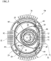
- Fig. 1 is a plan view illustrating an internal structure of the rotary heat pump 100 according to a first embodiment with a perspective view of a second side housing 50.
- the rotary heat pump 100 includes a rotary drive section 60 and heat exchange fins 70 provided on an outer wall surface of the rotary drive section 60.
- the rotary drive section 60 in the present embodiment has a rotary shaft 10, a stationary gear 15, a rotor 20, a rotary housing 30, a first side housing 40, and the second side housing 50.
- a structure of this rotary drive section 60 is such that parts formed from a metal material and heat insulation portions 80 that are parts formed from a heat insulating material are alternately disposed in a circumferential direction.
- a form that employs a Wankel rotary drive section 60 in the rotary heat pump 100 will be described.
- a first end portion of the rotary shaft 10 is rotatably supported in an internal space of the rotary drive section 60, while a second end portion thereof projects outside of the rotary drive section 60 from an insertion hole (not illustrated) of the first side housing 40.
- the second end portion of the rotary shaft 10 is coupled with an output shaft of a prime mover provided outside of the rotary drive section 60 (note that neither the prime mover nor the output shaft is illustrated) by a well-known scheme.
- the stationary gear 15 which is inserted from an outer surface side of the first side housing 40 and through which the rotary shaft 10 is inserted is fixedly screwed into the insertion hole of the first side housing 40.
- an eccentric shaft is suitably used as in the case of a rotary engine.
- At least a required thickness range of an outer surface of the rotor 20 in the present embodiment is formed into an outer shape of a so-called Reuleaux triangle (Wankel rotor) by a heat insulating material, and a fitting hole 22 of the rotor 20 is fitted into a rotary journal 12 formed in the rotary shaft 10 so that the rotor 20 is fixed in a state of being rotatable together with the rotary shaft 10.
- a rotor gear 24 that has larger diameter dimensions than outside diameter dimensions of the stationary gear 15 and the fitting hole 22, that is formed on the same axis as the fitting hole 22, and that is engaged with the stationary gear 15 is formed in a central portion of the rotor 20.
- the stationary gear 15 and the rotor gear 24 fixed to the first side housing 40 are engaged with each other only in a required range in the circumferential direction. Therefore, when the rotary shaft 10 rotates, the rotor 20 makes a motion of an eccentric rotation around the rotary shaft 10 (stationary gear 15).
- the rotary housing 30 is formed into a cocoon-shaped cylindrical body (Wankel rotary housing) that can planarly demarcate a radially outward region of the rotor 20 along a peritrochoid curve defined by the eccentric rotation of the rotor 20.
- One opening surface of the rotary housing 30 is covered with the first side housing 40 in which the insertion hole (not illustrated) for inserting the stationary gear 15 into an interior of the rotary housing 30 (rotary drive section 60) is formed.
- the rotary shaft 10 is inserted into the stationary gear 15, and the rotary shaft 10, the stationary gear 15, and the first side housing 40 are sealed by a well-known scheme.
- the second side housing 50 is mounted to the other opening surface of the rotary housing 30 in a state of being sealed with the rotary housing 30.
- Basic configurations of such a rotary drive section 60 can be designed similar to configurations of a so-called rotary engine from which intake/exhaust sections and an ignition sections are excluded.
- it is preferable that spaces surrounded by the rotor 20, the rotary housing 30, the first side housing 40, and the second side housing 50 are sealed with seal members (not illustrated) provided appropriately. Each of the spaces is filled with helium that is an example of a refrigerant.
- the heat exchange fins 70 are provided in a plurality of circumferential locations each over a required range on an outer surface of the rotary housing 30.
- a shape and a planar area of a region demarcated by an inner circumferential surface of the rotary housing 30 and an outer circumferential surface of the rotor 20 vary with the eccentric rotation of the rotor 20.
- two compression regions 32 where a demarcated region has a smallest planar area and two expansion regions 34 where the demarcated region has a largest planar area are formed, and the compression areas 32 and the expansion region 34 are alternately disposed at intervals of 90 degrees in the circumferential direction of the rotary housing 30 with a planar central portion of the rotary housing 30 assumed as a rotation center.
- the fins provided upright on the outer wall surface of the rotary drive section 60 at positions corresponding to the compression regions 32 that are high-temperature regions are heat dissipation fins 72 and the fins provided upright on the outer wall surface of the rotary drive section 60 at positions corresponding to the expansion regions 34 that are low-temperature regions are heat absorption fins 74.
- helium that is the refrigerant and that is filled in the internal space of the rotary drive section 60 is sequentially fed to the compression regions 32 and the expansion regions 34 that appear alternately in the circumferential direction of the rotary housing 30 to switch over between a high-temperature state and a low-temperature state.
- required range portions including at least boundaries between the compression regions 32 and the expansion regions 34 in the circumferential direction of the rotary housing 30, the first side housing 40, and the second side housing 50 are formed from the heat insulating material, and the heat insulating material portions serve as the heat insulation portions 80.
- first side housing 40 and the second side housing 50 are entirely formed from the heat insulating material.
- a fully gas phase Carnot cycle heat pump structure can be provided. While the rotor 20 according to the present embodiment rotates once in an internal space of the rotary housing 30, each of heat dissipation and heat absorption can be performed twice. These operations can ensure efficient heat exchange while ensuring small-sized, lightweight configurations and low noise. In addition, by accelerating the rotation of the output shaft of the prime mover to increase a revolving speed of the rotor 20, rapid heating and rapid cooling can be conveniently ensured.
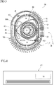
- Fig. 2 is a perspective plan view of the second side housing 50 of the rotary heat pump 100 according to a second embodiment, and illustrates a state in which the internal structure of the rotary heat pump 100 is depicted.
- same configurations as those in the first embodiment are denoted by the same reference signs used in the first embodiment and detailed descriptions of the configurations are omitted herein.
- the rotary heat pump 100 according to the present embodiment is characterized by further having a bypass path 90 that communicates the two expansion regions 34 with each other, compared with the configurations described in the first embodiment. Furthermore, the rotary heat pump 100 differs from the rotary heat pump 100 according to the first embodiment in that each of a series of heat dissipation fins 72 and a series of heat absorption fin 74 are provided upright in one location and that the heat insulation portions 80 are provided only in two locations.
- the bypass path 90 is coupled to bypass holes 34A penetrating the rotary housing 30 in the expansion regions 34, respectively.
- the heat absorption fins 74 are provided upright only on the outer wall surface of the rotary housing 30 corresponding to the expansion region 34 provided right after the compression region 32.
- the expansion region 34 (expansion region 34 located right before the compression region 32 that is the high-temperature region) communicated with the above expansion region 34 by the bypass path 90 may be entirely formed in the heat insulation portion 80.
- a bypass path heat sink 92 can be provided on the bypass path 90.
- helium is not substantially compressed in the compression region 32 at a position put between the expansion regions 34 that are brought into communication by the bypass path 90 in the rotary heat pump 100 according to the present embodiment, so that this part is not provided with the heat dissipation fins 72 or the heat insulation portion 80.
- the number of the heat dissipation fins 72, the heat absorption fins 74, and the heat insulation portions 80 to be provided can be reduced, so that it is conveniently possible to contribute to further miniaturization, weight reduction, and manufacturing cost reduction of the rotary heat pump 100.
- the rotary heat pump 100 according to the present invention has been described on the basis of the embodiments; however, the present invention is not limited to the above embodiments.
- the form in which the rotary heat pump 100 according to the embodiments described above employs the Wankel rotary drive section 60 has been described; however, the present invention is not limited to this structure and a structure of a well-known rotary drive section 60 can be applied as appropriate.
- a plurality of, i.e., three or more expansion regions 34 may be communicated with one another by the bypass path 90. It is thereby possible to provide expansion areas formed from the plurality of expansion regions 34 in a plurality of locations in the circumferential direction of the rotary drive section 60.
- the bypass holes 34A are provided in the rotary housing 30 in the expansion regions 34 and the bypass path 90 is coupled with the bypass holes 34A; however, the present invention is not limited to this form.
- the rotary heat pump 100 can have a form in which the bypass holes 34A passing through the first side housing 40 in a thickness direction are provided as an alternative to the bypass holes 34A provided in the rotary housing 30, and in which the bypass holes 34A in a plurality of expansion regions 34 are coupled together by the bypass path 90.
- These bypass holes 34A can also be provided in the second side housing 50 instead of the first side housing 40, or can be provided in both the first side housing 40 and the second side housing 50.
- bypass path heat sink 92 is provided on the bypass path 90 and in which heat exchange (heat absorption) can be also performed in the bypass path 90
- the bypass path 90 can be formed from a heat insulating material or a form in which the bypass path heat sink 92 is not provided can be employed.
- helium with high heat conductivity is filled into the rotary drive section 60 as the refrigerant
- the refrigerant with such properties is not limited to helium and a well-known refrigerant such as hydrogen or carbon dioxide can be used as appropriate.
- FIG. 4 there is also an invention as an air conditioner 200 equipped with the rotary heat pump 100 described above.
- FIG. 5 there is also an invention of an automobile 300 to which the air conditioner 200 equipped with the rotary heat pump 100 described in the present embodiments is attached. Since specific configurations of the air conditioner 200 and the automobile 300 are well known, detailed descriptions thereof are omitted herein.
- the air conditioner 200 according to the present invention can realize miniaturization, weight reduction, and high efficiency.
- the automobile 300 according to the present invention can not only realize the miniaturization and the weight reduction but also accelerate electrification of the automobile 300 by greatly saving energy.
- a form in which the rotary heat pumps 100 described above are disposed in series in an axial direction of the rotary shaft 10 can be employed. This results in an increase in an occupied volume of the rotary heat pumps 100; however, if a long and thin space can be allocated, it is possible to provide the rotary heat pump 100 with a higher performance and the air conditioner 200 and the automobile 300 each equipped with this rotary heat pump 100.
Landscapes
- Engineering & Computer Science (AREA)
- Mechanical Engineering (AREA)
- General Engineering & Computer Science (AREA)
- Chemical & Material Sciences (AREA)
- Combustion & Propulsion (AREA)
- Physics & Mathematics (AREA)
- Thermal Sciences (AREA)
- Applications Or Details Of Rotary Compressors (AREA)
- Details And Applications Of Rotary Liquid Pumps (AREA)
- Rotary Pumps (AREA)
Applications Claiming Priority (1)
| Application Number | Priority Date | Filing Date | Title |
|---|---|---|---|
| PCT/JP2021/000690 WO2022153364A1 (ja) | 2021-01-12 | 2021-01-12 | ロータリー型ヒートポンプおよびこれが搭載されたエアコンおよび自動車 |
Publications (3)
| Publication Number | Publication Date |
|---|---|
| EP4112938A1 true EP4112938A1 (de) | 2023-01-04 |
| EP4112938A4 EP4112938A4 (de) | 2023-07-19 |
| EP4112938B1 EP4112938B1 (de) | 2025-06-25 |
Family
ID=80629614
Family Applications (1)
| Application Number | Title | Priority Date | Filing Date |
|---|---|---|---|
| EP21919260.6A Active EP4112938B1 (de) | 2021-01-12 | 2021-01-12 | Rotationswärmepumpe sowie klimaanlage und kraftfahrzeug damit |
Country Status (6)
| Country | Link |
|---|---|
| US (1) | US11988166B2 (de) |
| EP (1) | EP4112938B1 (de) |
| JP (1) | JP7007776B1 (de) |
| KR (1) | KR102799855B1 (de) |
| CN (1) | CN115443380B (de) |
| WO (2) | WO2022153364A1 (de) |
Families Citing this family (4)
| Publication number | Priority date | Publication date | Assignee | Title |
|---|---|---|---|---|
| WO2024053075A1 (ja) * | 2022-09-09 | 2024-03-14 | 丸子警報器株式会社 | 電動移動体の駆動系機器冷却装置 |
| JP7549382B2 (ja) * | 2022-12-27 | 2024-09-11 | 丸子警報器株式会社 | ロータリー駆動部とロータリー型ヒートポンプ |
| WO2025046833A1 (ja) * | 2023-08-31 | 2025-03-06 | 三菱電機ビルソリューションズ株式会社 | エレベーターシステム |
| DE102024203305A1 (de) * | 2024-04-11 | 2025-10-16 | Zf Friedrichshafen Ag | Kreisprozessvorrichtung, Achsaggregat, Fahrzeug und Verfahren |
Family Cites Families (14)
| Publication number | Priority date | Publication date | Assignee | Title |
|---|---|---|---|---|
| US3042009A (en) * | 1958-10-02 | 1962-07-03 | Nsu Motorenwerke Ag | Cooling arrangement for rotary mechanisms |
| BE789541A (fr) | 1970-11-04 | 1973-01-15 | Barrett George M | Moteur thermique a faible pollution |
| US4357800A (en) * | 1979-12-17 | 1982-11-09 | Hecker Walter G | Rotary heat engine |
| JPH02118363A (ja) | 1988-10-28 | 1990-05-02 | Mazda Motor Corp | ヒートポンプ装置 |
| JPH03117658A (ja) * | 1989-09-29 | 1991-05-20 | Mazda Motor Corp | 外燃式ロータリピストンエンジン |
| CN100398829C (zh) * | 2002-11-26 | 2008-07-02 | 乐金电子(天津)电器有限公司 | 防止汪克尔型压缩机磨损的结构 |
| US20040200217A1 (en) | 2003-04-08 | 2004-10-14 | Marchetti George A | Bladed heat transfer stator elements for a stirling rotary engine |
| US8839623B2 (en) | 2005-09-06 | 2014-09-23 | Da Vinci Co., Ltd. | Rotary heat engine |
| JP2008038879A (ja) | 2006-08-03 | 2008-02-21 | Teratekku:Kk | ロータリー式スターリングエンジン |
| CN102112701A (zh) * | 2008-08-01 | 2011-06-29 | 株式会社达·芬奇 | 汪克尔型转子发动机 |
| WO2010125375A2 (en) | 2009-04-27 | 2010-11-04 | Ip Consortium Limited | Rotor side seal and method of sealing a rotor |
| FR2961266B1 (fr) * | 2010-06-11 | 2015-07-17 | Bernard Macarez | Moteur thermique a culasse echangeur |
| US20150260091A1 (en) * | 2014-03-14 | 2015-09-17 | Chung-Shan Institute Of Science And Technology, Armaments Bureau, M.N.D | External cooling fin for rotary engine |
| US20160305315A1 (en) * | 2014-03-14 | 2016-10-20 | National Chung_Shan Institute Of Science And Technology | External cooling fin for rotary engine |
-
2021
- 2021-01-12 EP EP21919260.6A patent/EP4112938B1/de active Active
- 2021-01-12 US US18/017,688 patent/US11988166B2/en active Active
- 2021-01-12 JP JP2021517497A patent/JP7007776B1/ja active Active
- 2021-01-12 CN CN202180029858.9A patent/CN115443380B/zh active Active
- 2021-01-12 WO PCT/JP2021/000690 patent/WO2022153364A1/ja not_active Ceased
- 2021-01-12 KR KR1020227035222A patent/KR102799855B1/ko active Active
- 2021-12-06 WO PCT/JP2021/044696 patent/WO2022153714A1/ja not_active Ceased
Also Published As
| Publication number | Publication date |
|---|---|
| KR20220148288A (ko) | 2022-11-04 |
| WO2022153714A1 (ja) | 2022-07-21 |
| EP4112938A4 (de) | 2023-07-19 |
| KR102799855B1 (ko) | 2025-04-29 |
| US11988166B2 (en) | 2024-05-21 |
| WO2022153364A1 (ja) | 2022-07-21 |
| EP4112938B1 (de) | 2025-06-25 |
| JP7007776B1 (ja) | 2022-01-25 |
| CN115443380A (zh) | 2022-12-06 |
| JPWO2022153364A1 (de) | 2022-07-21 |
| US20230279824A1 (en) | 2023-09-07 |
| CN115443380B (zh) | 2025-08-26 |
Similar Documents
| Publication | Publication Date | Title |
|---|---|---|
| US11988166B2 (en) | Rotary heat pump | |
| EP1209362B1 (de) | Hermetischer Verdichter | |
| US7147443B2 (en) | Electric compressor | |
| JP3818213B2 (ja) | 電動圧縮機 | |
| US6503069B2 (en) | Scroll-type compressor with an integrated motor and a compact cooling system | |
| US7179068B2 (en) | Electric compressor | |
| CN206429397U (zh) | 压缩机和具有其的车辆 | |
| JP2007224809A (ja) | 電動圧縮機 | |
| CN206206161U (zh) | 双驱动压缩机 | |
| JP2012132435A (ja) | 空気調和機 | |
| TW202233957A (zh) | 旋轉式熱泵和搭載有此旋轉式熱泵之空氣調節器、以及汽車 | |
| CN105840513B (zh) | 一种双滚动活塞式电动压缩机 | |
| JP4225101B2 (ja) | 電動圧縮機 | |
| CN205036581U (zh) | 旋转式压缩机及具有其的制冷循环装置 | |
| CN107842499A (zh) | 双驱动压缩机 | |
| JP7818306B2 (ja) | 電動移動体の駆動系機器冷却装置 | |
| WO2018054285A1 (zh) | 压缩机 | |
| CN109838381B (zh) | 涡旋压缩机 | |
| JP2013072411A (ja) | 電動圧縮機 | |
| JP4104534B2 (ja) | 密閉型圧縮機 | |
| JP2007002705A (ja) | 電動圧縮機 | |
| JP2023078810A (ja) | スクロール圧縮機 | |
| CN105329065A (zh) | 电动公交大巴的空调系统 | |
| JP2007162580A (ja) | 圧縮機 |
Legal Events
| Date | Code | Title | Description |
|---|---|---|---|
| STAA | Information on the status of an ep patent application or granted ep patent |
Free format text: STATUS: THE INTERNATIONAL PUBLICATION HAS BEEN MADE |
|
| PUAI | Public reference made under article 153(3) epc to a published international application that has entered the european phase |
Free format text: ORIGINAL CODE: 0009012 |
|
| STAA | Information on the status of an ep patent application or granted ep patent |
Free format text: STATUS: REQUEST FOR EXAMINATION WAS MADE |
|
| 17P | Request for examination filed |
Effective date: 20220930 |
|
| AK | Designated contracting states |
Kind code of ref document: A1 Designated state(s): AL AT BE BG CH CY CZ DE DK EE ES FI FR GB GR HR HU IE IS IT LI LT LU LV MC MK MT NL NO PL PT RO RS SE SI SK SM TR |
|
| REG | Reference to a national code |
Ref country code: DE Ref legal event code: R079 Free format text: PREVIOUS MAIN CLASS: F04C0018220000 Ipc: F01C0001220000 Ref country code: DE Ref legal event code: R079 Ref document number: 602021033106 Country of ref document: DE Free format text: PREVIOUS MAIN CLASS: F04C0018220000 Ipc: F01C0001220000 |
|
| A4 | Supplementary search report drawn up and despatched |
Effective date: 20230621 |
|
| RIC1 | Information provided on ipc code assigned before grant |
Ipc: F01C 1/22 20060101AFI20230615BHEP |
|
| DAV | Request for validation of the european patent (deleted) | ||
| DAX | Request for extension of the european patent (deleted) | ||
| GRAP | Despatch of communication of intention to grant a patent |
Free format text: ORIGINAL CODE: EPIDOSNIGR1 |
|
| STAA | Information on the status of an ep patent application or granted ep patent |
Free format text: STATUS: GRANT OF PATENT IS INTENDED |
|
| INTG | Intention to grant announced |
Effective date: 20250227 |
|
| GRAS | Grant fee paid |
Free format text: ORIGINAL CODE: EPIDOSNIGR3 |
|
| GRAA | (expected) grant |
Free format text: ORIGINAL CODE: 0009210 |
|
| STAA | Information on the status of an ep patent application or granted ep patent |
Free format text: STATUS: THE PATENT HAS BEEN GRANTED |
|
| P01 | Opt-out of the competence of the unified patent court (upc) registered |
Free format text: CASE NUMBER: APP_19890/2025 Effective date: 20250425 |
|
| AK | Designated contracting states |
Kind code of ref document: B1 Designated state(s): AL AT BE BG CH CY CZ DE DK EE ES FI FR GB GR HR HU IE IS IT LI LT LU LV MC MK MT NL NO PL PT RO RS SE SI SK SM TR |
|
| REG | Reference to a national code |
Ref country code: GB Ref legal event code: FG4D |
|
| REG | Reference to a national code |
Ref country code: CH Ref legal event code: EP |
|
| REG | Reference to a national code |
Ref country code: CH Ref legal event code: EP |
|
| REG | Reference to a national code |
Ref country code: IE Ref legal event code: FG4D |
|
| REG | Reference to a national code |
Ref country code: DE Ref legal event code: R096 Ref document number: 602021033106 Country of ref document: DE |
|
| PG25 | Lapsed in a contracting state [announced via postgrant information from national office to epo] |
Ref country code: FI Free format text: LAPSE BECAUSE OF FAILURE TO SUBMIT A TRANSLATION OF THE DESCRIPTION OR TO PAY THE FEE WITHIN THE PRESCRIBED TIME-LIMIT Effective date: 20250625 |
|
| REG | Reference to a national code |
Ref country code: LT Ref legal event code: MG9D |
|
| PG25 | Lapsed in a contracting state [announced via postgrant information from national office to epo] |
Ref country code: NO Free format text: LAPSE BECAUSE OF FAILURE TO SUBMIT A TRANSLATION OF THE DESCRIPTION OR TO PAY THE FEE WITHIN THE PRESCRIBED TIME-LIMIT Effective date: 20250925 Ref country code: GR Free format text: LAPSE BECAUSE OF FAILURE TO SUBMIT A TRANSLATION OF THE DESCRIPTION OR TO PAY THE FEE WITHIN THE PRESCRIBED TIME-LIMIT Effective date: 20250926 |
|
| PG25 | Lapsed in a contracting state [announced via postgrant information from national office to epo] |
Ref country code: BG Free format text: LAPSE BECAUSE OF FAILURE TO SUBMIT A TRANSLATION OF THE DESCRIPTION OR TO PAY THE FEE WITHIN THE PRESCRIBED TIME-LIMIT Effective date: 20250625 |
|
| PG25 | Lapsed in a contracting state [announced via postgrant information from national office to epo] |
Ref country code: HR Free format text: LAPSE BECAUSE OF FAILURE TO SUBMIT A TRANSLATION OF THE DESCRIPTION OR TO PAY THE FEE WITHIN THE PRESCRIBED TIME-LIMIT Effective date: 20250625 |
|
| PG25 | Lapsed in a contracting state [announced via postgrant information from national office to epo] |
Ref country code: RS Free format text: LAPSE BECAUSE OF FAILURE TO SUBMIT A TRANSLATION OF THE DESCRIPTION OR TO PAY THE FEE WITHIN THE PRESCRIBED TIME-LIMIT Effective date: 20250925 |
|
| PG25 | Lapsed in a contracting state [announced via postgrant information from national office to epo] |
Ref country code: LV Free format text: LAPSE BECAUSE OF FAILURE TO SUBMIT A TRANSLATION OF THE DESCRIPTION OR TO PAY THE FEE WITHIN THE PRESCRIBED TIME-LIMIT Effective date: 20250625 |
|
| REG | Reference to a national code |
Ref country code: NL Ref legal event code: MP Effective date: 20250625 |
|
| PG25 | Lapsed in a contracting state [announced via postgrant information from national office to epo] |
Ref country code: NL Free format text: LAPSE BECAUSE OF FAILURE TO SUBMIT A TRANSLATION OF THE DESCRIPTION OR TO PAY THE FEE WITHIN THE PRESCRIBED TIME-LIMIT Effective date: 20250625 |
|
| PG25 | Lapsed in a contracting state [announced via postgrant information from national office to epo] |
Ref country code: PT Free format text: LAPSE BECAUSE OF FAILURE TO SUBMIT A TRANSLATION OF THE DESCRIPTION OR TO PAY THE FEE WITHIN THE PRESCRIBED TIME-LIMIT Effective date: 20251027 |
|
| REG | Reference to a national code |
Ref country code: AT Ref legal event code: MK05 Ref document number: 1806625 Country of ref document: AT Kind code of ref document: T Effective date: 20250625 |
|
| PG25 | Lapsed in a contracting state [announced via postgrant information from national office to epo] |
Ref country code: IS Free format text: LAPSE BECAUSE OF FAILURE TO SUBMIT A TRANSLATION OF THE DESCRIPTION OR TO PAY THE FEE WITHIN THE PRESCRIBED TIME-LIMIT Effective date: 20251025 |
|
| PG25 | Lapsed in a contracting state [announced via postgrant information from national office to epo] |
Ref country code: AT Free format text: LAPSE BECAUSE OF FAILURE TO SUBMIT A TRANSLATION OF THE DESCRIPTION OR TO PAY THE FEE WITHIN THE PRESCRIBED TIME-LIMIT Effective date: 20250625 Ref country code: SM Free format text: LAPSE BECAUSE OF FAILURE TO SUBMIT A TRANSLATION OF THE DESCRIPTION OR TO PAY THE FEE WITHIN THE PRESCRIBED TIME-LIMIT Effective date: 20250625 |
|
| PGFP | Annual fee paid to national office [announced via postgrant information from national office to epo] |
Ref country code: FR Payment date: 20251217 Year of fee payment: 6 |
|
| PG25 | Lapsed in a contracting state [announced via postgrant information from national office to epo] |
Ref country code: CZ Free format text: LAPSE BECAUSE OF FAILURE TO SUBMIT A TRANSLATION OF THE DESCRIPTION OR TO PAY THE FEE WITHIN THE PRESCRIBED TIME-LIMIT Effective date: 20250625 |
|
| PG25 | Lapsed in a contracting state [announced via postgrant information from national office to epo] |
Ref country code: PL Free format text: LAPSE BECAUSE OF FAILURE TO SUBMIT A TRANSLATION OF THE DESCRIPTION OR TO PAY THE FEE WITHIN THE PRESCRIBED TIME-LIMIT Effective date: 20250625 |
|
| PG25 | Lapsed in a contracting state [announced via postgrant information from national office to epo] |
Ref country code: EE Free format text: LAPSE BECAUSE OF FAILURE TO SUBMIT A TRANSLATION OF THE DESCRIPTION OR TO PAY THE FEE WITHIN THE PRESCRIBED TIME-LIMIT Effective date: 20250625 |
|
| PG25 | Lapsed in a contracting state [announced via postgrant information from national office to epo] |
Ref country code: SK Free format text: LAPSE BECAUSE OF FAILURE TO SUBMIT A TRANSLATION OF THE DESCRIPTION OR TO PAY THE FEE WITHIN THE PRESCRIBED TIME-LIMIT Effective date: 20250625 |
|
| PG25 | Lapsed in a contracting state [announced via postgrant information from national office to epo] |
Ref country code: ES Free format text: LAPSE BECAUSE OF FAILURE TO SUBMIT A TRANSLATION OF THE DESCRIPTION OR TO PAY THE FEE WITHIN THE PRESCRIBED TIME-LIMIT Effective date: 20250625 |
|
| PG25 | Lapsed in a contracting state [announced via postgrant information from national office to epo] |
Ref country code: DK Free format text: LAPSE BECAUSE OF FAILURE TO SUBMIT A TRANSLATION OF THE DESCRIPTION OR TO PAY THE FEE WITHIN THE PRESCRIBED TIME-LIMIT Effective date: 20250625 |
|
| PGFP | Annual fee paid to national office [announced via postgrant information from national office to epo] |
Ref country code: DE Payment date: 20251219 Year of fee payment: 6 |
|
| PG25 | Lapsed in a contracting state [announced via postgrant information from national office to epo] |
Ref country code: IT Free format text: LAPSE BECAUSE OF FAILURE TO SUBMIT A TRANSLATION OF THE DESCRIPTION OR TO PAY THE FEE WITHIN THE PRESCRIBED TIME-LIMIT Effective date: 20250625 |