EP4112306B1 - Heissfolienprägepresse - Google Patents
Heissfolienprägepresse Download PDFInfo
- Publication number
- EP4112306B1 EP4112306B1 EP21183041.9A EP21183041A EP4112306B1 EP 4112306 B1 EP4112306 B1 EP 4112306B1 EP 21183041 A EP21183041 A EP 21183041A EP 4112306 B1 EP4112306 B1 EP 4112306B1
- Authority
- EP
- European Patent Office
- Prior art keywords
- hook element
- foil stamping
- door
- hot foil
- stamping press
- Prior art date
- Legal status (The legal status is an assumption and is not a legal conclusion. Google has not performed a legal analysis and makes no representation as to the accuracy of the status listed.)
- Active
Links
Images


Classifications
-
- B—PERFORMING OPERATIONS; TRANSPORTING
- B41—PRINTING; LINING MACHINES; TYPEWRITERS; STAMPS
- B41F—PRINTING MACHINES OR PRESSES
- B41F16/00—Transfer printing apparatus
- B41F16/0006—Transfer printing apparatus for printing from an inked or preprinted foil or band
- B41F16/004—Presses of the reciprocating type
- B41F16/0046—Presses of the reciprocating type with means for applying print under heat and pressure, e.g. using heat activable adhesive
-
- B—PERFORMING OPERATIONS; TRANSPORTING
- B41—PRINTING; LINING MACHINES; TYPEWRITERS; STAMPS
- B41F—PRINTING MACHINES OR PRESSES
- B41F16/00—Transfer printing apparatus
- B41F16/0006—Transfer printing apparatus for printing from an inked or preprinted foil or band
- B41F16/006—Arrangements for moving, supporting or positioning the printing foil or band
-
- B—PERFORMING OPERATIONS; TRANSPORTING
- B41—PRINTING; LINING MACHINES; TYPEWRITERS; STAMPS
- B41F—PRINTING MACHINES OR PRESSES
- B41F19/00—Apparatus or machines for carrying out printing operations combined with other operations
- B41F19/02—Apparatus or machines for carrying out printing operations combined with other operations with embossing
- B41F19/06—Printing and embossing between a negative and a positive forme after inking and wiping the negative forme; Printing from an ink band treated with colour or "gold"
- B41F19/064—Presses of the reciprocating type
- B41F19/068—Presses of the reciprocating type motor-driven
-
- B—PERFORMING OPERATIONS; TRANSPORTING
- B41—PRINTING; LINING MACHINES; TYPEWRITERS; STAMPS
- B41F—PRINTING MACHINES OR PRESSES
- B41F1/00—Platen presses, i.e. presses in which printing is effected by at least one essentially-flat pressure-applying member co-operating with a flat type-bed
- B41F1/26—Details
- B41F1/38—Platens or type-beds
-
- B—PERFORMING OPERATIONS; TRANSPORTING
- B41—PRINTING; LINING MACHINES; TYPEWRITERS; STAMPS
- B41F—PRINTING MACHINES OR PRESSES
- B41F16/00—Transfer printing apparatus
- B41F16/0006—Transfer printing apparatus for printing from an inked or preprinted foil or band
-
- B—PERFORMING OPERATIONS; TRANSPORTING
- B41—PRINTING; LINING MACHINES; TYPEWRITERS; STAMPS
- B41P—INDEXING SCHEME RELATING TO PRINTING, LINING MACHINES, TYPEWRITERS, AND TO STAMPS
- B41P2219/00—Printing presses using a heated printing foil
Definitions
- the invention relates to a hot foil stamping press comprising a platen press.
- Hot foil stamping is a method for transferring patterns and texts from a foil onto a sheet at high temperatures.
- the sheet can be cardboard or paper, and the foil is either a metallized plastic foil or a thin metal foil.
- the foil is pressed onto the surface of the sheet so that part of the foil is transferred to the sheet where it adheres.
- a platen press comprises an upper and a lower platen.
- a supporting plate is installed to perform the hot stamping of the foil.
- the thickness of the supporting plate must be set with a precision to a few tens of microns.
- the supporting plate can be made of two pieces, a lower base part and a top plate (top part), called the compensating plate. Between the base part and a top plate, a so-called “makeready sheet” is placed at selected locations to control and/or set the pressure at each location of the whole surface of the platen.
- the compensating plate is lifted and kept in a lifted position to allow an operator to install the makeready sheet.
- the hot foil stamping press should provide for an easy and fast set-up procedure.
- a hot foil stamping press comprising a platen press with a supporting plate comprising a base plate and a compensating plate being rotatably attached to the base plate for switching between an operating position and a makeready position and a hook element comprising a base part and a top part being arranged at an angle relative to the base part.
- the hook element is rotatably attached to a door of the platen press by a fixation axle for switching between a releasing position and a securing position of the hook element, wherein the top part retains the compensating plate in its makeready position when the hook element is in its securing position.
- a basic idea of the invention is that the top part of the supporting plate can easily be secured in its makeready position by the hook element provided at a door of the platen press. This allows a flexible arrangement of the top part in its makeready position relative to the base plate. Especially, the top part is not restricted to be brought into a vertical position, thereby allowing to optimize the makeready position in regard to the available space in front of the platen press.
- the door is arranged at an operator side (OS) of the platen press to allow an operator of the hot foil stamping press to easily access the supporting plate and the hook element during setup of the supporting plate.
- OS operator side
- the compensating plate In the makeready position, the compensating plate is arranged close to the door of the platen press for interaction with the hook element. E.g., the compensating plate is arranged essentially parallel or at an angle relative to the door.
- At an angle means that there is an angle between the respective parts which is in the range between 0° and 180°, i.e. not equal to 0° or 180°.
- the hot foil stamping press is preferably a cross-foil stamping press.
- the hook element can be held in its securing position by an elastic element.
- the elastic element is a spring, which preferably exerts a force on the compensating plate in the securing position.
- the top part of the hook element preferably comprises a manipulating element by which the hook element can be switched between the releasing position and the securing position.
- the manipulating element especially is manually operable by the operator of the hot foil stamping press.
- the manipulating element can be a knob, a grip, a handle or a recess.
- the manipulating element is a recess which is operable by a single finger of the operator. Accordingly, in this alternative, the operator needs only one hand for manipulating the hook element such that the operator at the same time can handle the compensating plate.
- first and second door sections can be arranged such that they encompass, i.e. essentially fold around, parts of the platen press like bobbins or rolls which provide foil for the hot foil stamping operation.
- the first and second door section can encompass bobbins on which foil is wound which is provided to the sheets which are to be processed from a direction perpendicular to a feeding direction of the sheets.
- the base part of the hook element can be essentially parallel to the first door section or the second door section.
- the compensating plate is arranged at an angle between 0° and 90° relative to the first door section, preferably at angle between 0° and 40°.
- a second hook element is rotatably attached to the door of the platen press, wherein the second hook element comprises a second base part and a second top part being arranged at an angle relative to the second base part.
- the second base part of the second hook element is rotatably attached to the door by a second fixation axle for switching between a releasing position and a securing position.
- the second hook element allows a further increased stabilization of the compensating plate in the makeready position. Further, in case the compensating plate is made of a flexible material, the second hook element can prevent warping and/or tilting of the compensating plate when being held in the makeready positon by the hook elements. Thus, mechanical stress on the compensating plate can be reduced, thereby minimizing the risk of damaging the compensating plate during set-up of the platen press.
- the second hook element also has a second base part and a second top part like the hook element, the second hook element is not necessarily identical to the hook element.
- the hook element and the second hook element can be connected by a connection element such that the second hook element is in the releasing position when the hook element is in the releasing position and the second hook element is in the securing position when the hook element is in the securing position.
- the hook element and the second hook element undergo a coupled motion when switching between their respective releasing positions and securing positions.
- only the hook element or the second hook element need to be manipulated by the operator of the hot foil stamping press when the compensating plate needs to be secured in its makeready position. This allows the operator to reliably secure the compensating plate with a single hand while the other hand can e.g. hold the compensating plate in the desired position.
- connection element is a bar rotatably connected at a first end to the base part of the hook element and rotatably connected at a second end to the second base part of the second hook element.
- the hook element and the second hook element can rotate into opposite directions when switching from their respective releasing position to their respective securing position.
- connection element on different sides of the respective fixation axles of the hook element and the second hook element.
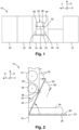
- Fig. 1 schematically shows a hot foil stamping press 10 comprising a series of processing stations that are juxtaposed but interdependent on each other and form a unitary assembly.
- the hot foil stamping press 10 includes, along a feeding direction F, a loading station 12 for loading sheets into the hot foil stamping press 10, followed by an inspection table 14, a platen press 16, a foil feed module 18 and an evacuation station 20 for collecting and removing the processed sheets from the hot foil stamping press 10.
- the sheets to be processed by the hot foil stamping press 10 can be cardboard or paper onto which metallized plastic foil or a thin metal foil is applied in the platen press 16.
- the hot foil stamping press 10 is a cross-foil stamping press. Accordingly, in the platen press 16, metallized plastic foil or thin metal foil can be applied from the foil feed module 18 to the platen press 16 perpendicular to the feeding direction F along a depth direction D within the platen press 16.
- Fig. 2 a cut through selected parts of the platen press 16 of the hot foil stamping press 10 is shown.
- the platen press 16 comprises a supporting plate 22 which can be inserted into and extracted from the platen press 16 by a pair of guides 24.
- the supporting plate 22 has a lower base plate 26 and a compensating plate 28 rotatably attached to the base plate 26.
- the compensating plate 28 can be switched between an operating position, in which the compensating plate is essentially parallel to the base plate 26 (shown in Fig. 2 as compensating plate 28' with dashed lines), to a makeready position as indicated by the arrow in Fig. 2 .
- a makeready sheet (not shown) can be placed by an operator of the hot foil stamping press on the base plate 26.
- the makeready sheet is used to toggle and/or set up the pressure achieved by the platen press 16 during the hot foil stamping process, especially by equalizing the thickness of the supporting plate 22.
- the platen press 16 has a door 30 comprising a first door section 32 and a second door section 34, wherein the second door section 34 is arranged at an angle relative to the first door section 32.
- the door 30 can be opened into an access position as indicated by the dashed representation of the door 30' in Fig. 2 .
- the operator In the access position, the operator has access to the inner of the platen press 16, e.g. to install and/or remove the bobbins 36 and 37.
- the door 30 limits the range of motion of the compensating plate 28.
- the compensating plate 28 can be arranged vertically along a height direction H when installing the makeready.
- the operator side of the hot foil stamping press 10 i.e. the side shown depicted on the right hand side of Fig. 2 , it is undesirable to extract the supporting plate 22 even further from the platen press 16.
- the hot foil stamping press 10 comprises a hook element 38.
- the hook element 38 has a base part 40 and a top part 42 being arranged at an angle ⁇ relative to the base part 40 (see Fig. 4 ).
- the hook element 38 is arranged close to an edge 39 connecting the first door section 32 and the second door section 34.
- the hook element 38 is connected to the door 30 by means of a fixation axle 44 (see Fig. 8 ).
- Fig. 2 the hook element 38 is shown in a securing position in which the hook element 38 retains the compensating plate 28 in its makeready position.
- the hook element 38 can be switched between the securing position shown in Fig. 2 and a releasing position in which the hook element 38 does not retain the compensating plate 28.
- the hook element 38 is rotatable around a rotation axis R 1 (see Figs. 4 to 6 ). Accordingly, the hook element 38 is rotatably connected to the door 30.
- Fig. 3 shows a schematic front view of the platen press of Fig. 2 in which the different parts of the platen press 16 are depicted in a folded manner.
- both the first door section 32 and the second door section 34 each comprise a respective window 46 which allows inspection of the interior of the platen press 16 during operation.
- the platen press 16 additionally comprises a second hook element 48 which is arranged opposite to the hook element 38 along the width of the door 30 and essentially at the same height along the height direction H. Specifically, the hook element 38 and the second hook element 48 are positioned close to the edge 39 connecting the first door section 32 and the second door section 34.
- the compensating plate 28 is held from both sides in its makeready position by means of the hook element 38 and the second hook element 48, such that warping or bending of the compensating plate 28 can be prevented, thereby minimizing mechanical stress on the compensating plate 28.
- Fig. 4 a side view of the hook element 38 is shown, in which the angled orientation between the base part 40 and the top part 42 is easily perceived.
- the angle ⁇ between the base part 40 and the top part 42 is approximately 35°.
- the angle ⁇ can be in the range between 0° and 90°.
- the angle ⁇ is in the range of from 20° to 70°.
- the hook element 38 is rotatable around the rotation axis R 1 as indicated by the double-arrow in Fig. 5 which shows a back view of the hook element 38.
- the hook element 38 In the orientation shown in Figs. 4 to 6 , the hook element 38 is in its securing position, i.e. the compensating plate 28 would be held by a contact surface 50 of the hook element 38.
- the hook element 38 e.g. would be rotated by 90° clockwise, based on the viewing direction used in Fig. 5 .
- the hook element 38 comprises an elastic element 52 which is a spring exerting a force F indicated in Fig. 5 .
- the elastic element 52 holds the hook element 38 in its securing position.
- Fig. 6 is a top view on the hook element 38 in which a manipulating element 58 of the hook element 38 can be seen.
- the manipulating element 58 is used by the operator of the hot foil stamping press 10 for switching between the releasing position and the securing position of the hook element 38.
- the manipulating element 58 is a recess in which a single finger of the operator can engage for controlling the hook element 38.
- the manipulating element 58 could be designed differently, e.g. the manipulating element 58 could be a handle, bar or knob.
- top part 42 of the hook element 38 has a sloped funnel surface 60.
- FIG. 7 the interaction between the hook element 38 and the second hook element 48 is illustrated.
- the second hook element 48 comprises a second base part 62 and a second top part 64 which is arranged at an angle to the second base part 62 and a contact surface 66, too, analogously to the hook element 38.
- the second hook element 48 is rotatably connected by a second fixation axle 68 to the door 30.
- hook element 38 and the second element hook element 48 have an analog structure, as can be seen in Fig. 7 , the hook element 38 and the second hook element 48 do not need to be structurally identical to each other.
- connection element 70 which in the shown embodiment is a rigid bar.
- the bar is rotatably connected with a first end 72 to the base part 40 of the hook element 38 and with a second end 74 to the second base part 62 of the second hook element 48.
- first end 72 and the second end 74 are connected at opposite sides of the respective fixation axles 44 and 68 of the hook element 38 and the second hook element 48 along the height direction H.
- the second hook element 48 is also switched from the securing position into the releasing position, but by a rotation around a rotation axis R 2 in opposite direction, shown in Fig. 7 by a counterclockwise rotation as indicated by arrow P 2 .
- the hot foil stamping press 10 provides a simple, easy to use and reliable mechanism for securing the compensating plate 28 during preparation of the supporting plate 22, thereby reducing the necessary space and set-up time of the hot foil stamping press 10.
- Fig. 8 shows a schematic arrangement of the hook element 38 relative to the door 30 of the platen press 16.
- the base part of the hook element 38 is essentially parallel to the first door section 32 of the door 30 of the platen press 16.
- the fixation axle 44 rotatably connects the hook element 38 to the first door section 32.
- FIG. 9 an alternative arrangement of the hook element 38 relative to the door 30 of the platen press 16 is shown.
- the base part 40 of the hook element 38 is essentially parallel to the second door section of the door 30 of the platen press 16 and the fixation axle 44 rotatably connects the hook element 38 to the second door section.
- the hook element 38 only needs minimal amounts of space on the side of the door 30 facing the inner of the platen press 16. Which of the arrangements is used can therefore be chosen based on the further parts of the platen press, e.g. based on the position of the bobbins 36 and 37 (see Fig. 2 ).
Landscapes
- Engineering & Computer Science (AREA)
- Mechanical Engineering (AREA)
- Press Drives And Press Lines (AREA)
- Duplication Or Marking (AREA)
- Labeling Devices (AREA)
Claims (9)
- Heißfolienprägepresse, umfassend einen Tiegel (16) miteiner Trägerplatte (22), die eine Basisplatte (26) und eine Ausgleichsplatte (28), die zum Umschalten zwischen einer Betriebsposition und einer Druckvorbereitungsposition drehbar an der Basisplatte (26) angebracht ist, umfasst,ein Hakenelement (38), das ein Basisteil (40) und ein Oberteil (42), das in einem Winkel in Bezug zum Basisteil (40) angeordnet ist, umfasst,wobei das Hakenelement (38) über eine Befestigungsachse (44) drehbar an einer Tür (30) des Tiegels (16) zum Umschalten zwischen einer Freigabeposition und einer Sicherungsposition des Hakenelements (38) angebracht ist,wobei das Oberteil (42) die Ausgleichsplatte (28) in ihrer Druckvorbereitungsposition hält, wenn sich das Hakenelement (38) in seiner Sicherungsposition befindet.
- Heißfolienprägepresse nach Anspruch 1, wobei das Hakenelement (38) durch ein elastisches Element (52) in seiner Sicherungsposition gehalten wird.
- Heißfolienprägepresse nach Anspruch 1 oder 2, wobei das Oberteil des Hakenelements (38) ein Handhabungselement (58) umfasst, mit dem das Hakenelement (38) zwischen der Freigabeposition und der Sicherungsposition umgeschaltet werden kann.
- Heißfolienprägepresse nach einem der vorstehenden Ansprüche, wobei die Tür (30) des Tiegels (16) einen ersten Türabschnitt (32) und einen zweiten Türabschnitt (34), der in einem Winkel in Bezug zum ersten Türabschnitt (32) angeordnet ist, umfasst.
- Heißfolienprägepresse nach Anspruch 4, wobei das Basisteil (40) des Hakenelements (38) im Wesentlichen parallel zum ersten Türabschnitt (32) oder zum zweiten Türabschnitt (34) ist.
- Heißfolienprägepresse nach Anspruch 4 oder 5, wobei die Ausgleichsplatte (28) in der Druckvorbereitungsposition in einem Winkel, der genau zwischen 0° und 180° umfasst ist, in Bezug auf den ersten Türabschnitt (32) positioniert ist.
- Heißfolienprägepresse nach einem der vorstehenden Ansprüche, wobei gegenüber dem Hakenelement (38) entlang einer Breitenrichtung der Tür (30) ein zweites Hakenelement (48) drehbar an der Tür des Tiegels (16) angebracht ist,wobei das zweite Hakenelement (48) ein zweites Basisteil (62) und ein zweites Oberteil (64), das in einem Winkel in Bezug zum zweiten Basisteil (62) angeordnet ist, umfasst, undwobei das zweite Basisteil (62) des zweiten Hakenelements (48) durch eine zweite Befestigungsachse (68) zum Umschalten zwischen einer Freigabeposition und einer Sicherungsposition des zweiten Hakenelements (48) drehbar an der Tür (30) angebracht ist.
- Heißfolienprägepresse nach Anspruch 7, wobei das Hakenelement (38) und das zweite Hakenelement (48) durch ein Verbindungselement (70) verbunden sind, sodass sich das zweite Hakenelement (48) in der Freigabeposition befindet, wenn sich das Hakenelement (38) in der Freigabeposition befindet, und sich das zweite Hakenelement (48) in der Sicherungsposition befindet, wenn sich das Hakenelement (38) in der Sicherungsposition befindet, und wobei das Verbindungselement (70) eine Stange ist, die an einem ersten Ende (72) drehbar mit dem Basisteil (40) des Hakenelements (38) verbunden ist und an einem zweiten Ende (74) drehbar mit dem zweiten Basisteil (62) des zweiten Hakenelements (48) verbunden ist.
- Heißfolienprägepresse nach einem der Ansprüche 7 bis 8, wobei sich das Hakenelement (38) und das zweite Hakenelement (48) beim Umschalten von ihrer jeweiligen Freigabeposition in ihre jeweilige Sicherungsposition in entgegengesetzte Richtungen drehen.
Priority Applications (3)
| Application Number | Priority Date | Filing Date | Title |
|---|---|---|---|
| EP21183041.9A EP4112306B1 (de) | 2021-07-01 | 2021-07-01 | Heissfolienprägepresse |
| US17/806,591 US11691410B2 (en) | 2021-07-01 | 2022-06-13 | Hot foil stamping press |
| CN202210732559.8A CN115556471B (zh) | 2021-07-01 | 2022-06-24 | 热箔压印机 |
Applications Claiming Priority (1)
| Application Number | Priority Date | Filing Date | Title |
|---|---|---|---|
| EP21183041.9A EP4112306B1 (de) | 2021-07-01 | 2021-07-01 | Heissfolienprägepresse |
Publications (2)
| Publication Number | Publication Date |
|---|---|
| EP4112306A1 EP4112306A1 (de) | 2023-01-04 |
| EP4112306B1 true EP4112306B1 (de) | 2025-03-26 |
Family
ID=76744642
Family Applications (1)
| Application Number | Title | Priority Date | Filing Date |
|---|---|---|---|
| EP21183041.9A Active EP4112306B1 (de) | 2021-07-01 | 2021-07-01 | Heissfolienprägepresse |
Country Status (3)
| Country | Link |
|---|---|
| US (1) | US11691410B2 (de) |
| EP (1) | EP4112306B1 (de) |
| CN (1) | CN115556471B (de) |
Family Cites Families (13)
| Publication number | Priority date | Publication date | Assignee | Title |
|---|---|---|---|---|
| US5273326A (en) * | 1991-08-14 | 1993-12-28 | Wells Cargo Inc. | Cargo door hold back |
| DE19610820C2 (de) * | 1996-03-19 | 2002-10-24 | Mitsubishi Paper Mills Ltd | Befestigungsvorrichtung für eine Druckplatte |
| US6302022B1 (en) * | 2000-10-20 | 2001-10-16 | Shiny Shih | Ink refillable stamp |
| ES2203303B1 (es) * | 2001-11-29 | 2005-02-16 | Rafael Pascual Bernabeu | Maquina para calandrar, estampar, flocar, grabar y cepillar simultaneamente. |
| ES2768241T3 (es) * | 2011-04-05 | 2020-06-22 | Bobst Mex Sa | Dispositivo de impresión por estampación en caliente |
| KR101246082B1 (ko) * | 2011-04-29 | 2013-03-21 | 주식회사 신흥정밀 | 써멀프린터의 커버프레임 개폐장치 |
| GB2519538A (en) * | 2013-10-23 | 2015-04-29 | Adkins And Sons Ltd A | Heat press and method of printing articles |
| US9289960B2 (en) * | 2014-04-02 | 2016-03-22 | GroupeSTAHL | Dual shuttle press |
| KR101741040B1 (ko) * | 2016-10-07 | 2017-05-29 | 김덕한 | 옆 고리 단추용 자동 재봉장치 |
| CN110228289B (zh) * | 2018-03-05 | 2022-07-15 | 博斯特(上海)有限公司 | 辊轴转换装置以及烫金模切设备 |
| CN113613907B (zh) | 2019-03-20 | 2023-06-09 | 鲍勃斯脱梅克斯股份有限公司 | 热箔压印机 |
| CN211640954U (zh) * | 2019-12-09 | 2020-10-09 | 江苏玉兰新材料科技有限公司 | 一种泡棉、铜箔、pe膜热压复合机 |
| US11878484B2 (en) * | 2020-08-05 | 2024-01-23 | ColDesi, Inc. | Ergonomic heat press |
-
2021
- 2021-07-01 EP EP21183041.9A patent/EP4112306B1/de active Active
-
2022
- 2022-06-13 US US17/806,591 patent/US11691410B2/en active Active
- 2022-06-24 CN CN202210732559.8A patent/CN115556471B/zh active Active
Also Published As
| Publication number | Publication date |
|---|---|
| EP4112306A1 (de) | 2023-01-04 |
| CN115556471B (zh) | 2025-04-11 |
| US20230001686A1 (en) | 2023-01-05 |
| CN115556471A (zh) | 2023-01-03 |
| US11691410B2 (en) | 2023-07-04 |
Similar Documents
| Publication | Publication Date | Title |
|---|---|---|
| US5129749A (en) | Line printer with pinch roller release | |
| CN103459135B (zh) | 热转印印制装置 | |
| US6227588B1 (en) | Gripper assembly | |
| JP5589376B2 (ja) | カバーユニットおよびプリンター | |
| US6776405B2 (en) | Imaging apparatus and methods | |
| JPS6246450B2 (de) | ||
| JP3764718B2 (ja) | 紙搬送車 | |
| JPH062403B2 (ja) | 輪転印刷機の印刷部間に配置される渡しドラム | |
| EP4112306B1 (de) | Heissfolienprägepresse | |
| EP3002130B1 (de) | Druckeinheit und drucker | |
| EP0551166A1 (de) | Vorrichtung zum Wechseln von Druckplatten in einer Druckmaschine | |
| EP2036844A2 (de) | Blattführungsvorrichtung | |
| JP2001220030A (ja) | シートを案内するためのガイド装置およびガイド装置を運転する方法 | |
| DE10258271A1 (de) | Vorrichtung zur Unterstützng der Andrückkraft einer Steuerrolle an eine zugehörige Steuerkurve | |
| EP2263878B1 (de) | Höheneinstellvorrichtung für eine Greiferleiste eines Transportzylinders | |
| JP2007326716A (ja) | 紙を把持する把持装置および方法 | |
| KR100551508B1 (ko) | 라미네이터 | |
| JP6573808B2 (ja) | 補助パイルと主パイルとを1つに纏める装置 | |
| JP3157705U (ja) | シート搬送装置 | |
| JP2013086282A (ja) | プリンタ装置 | |
| JP2001010020A (ja) | 刷版自動交換装置及び刷版自動交換方法 | |
| JP7459499B2 (ja) | 印刷装置 | |
| CN100569609C (zh) | 用于刀式折页装置的前边缘挡规 | |
| JP3312794B2 (ja) | 用紙給送装置 | |
| JP2009286088A (ja) | オフセット枚葉印刷機の刷版取り付け装置 |
Legal Events
| Date | Code | Title | Description |
|---|---|---|---|
| PUAI | Public reference made under article 153(3) epc to a published international application that has entered the european phase |
Free format text: ORIGINAL CODE: 0009012 |
|
| STAA | Information on the status of an ep patent application or granted ep patent |
Free format text: STATUS: THE APPLICATION HAS BEEN PUBLISHED |
|
| AK | Designated contracting states |
Kind code of ref document: A1 Designated state(s): AL AT BE BG CH CY CZ DE DK EE ES FI FR GB GR HR HU IE IS IT LI LT LU LV MC MK MT NL NO PL PT RO RS SE SI SK SM TR |
|
| STAA | Information on the status of an ep patent application or granted ep patent |
Free format text: STATUS: REQUEST FOR EXAMINATION WAS MADE |
|
| 17P | Request for examination filed |
Effective date: 20230703 |
|
| RBV | Designated contracting states (corrected) |
Designated state(s): AL AT BE BG CH CY CZ DE DK EE ES FI FR GB GR HR HU IE IS IT LI LT LU LV MC MK MT NL NO PL PT RO RS SE SI SK SM TR |
|
| GRAP | Despatch of communication of intention to grant a patent |
Free format text: ORIGINAL CODE: EPIDOSNIGR1 |
|
| STAA | Information on the status of an ep patent application or granted ep patent |
Free format text: STATUS: GRANT OF PATENT IS INTENDED |
|
| GRAS | Grant fee paid |
Free format text: ORIGINAL CODE: EPIDOSNIGR3 |
|
| GRAA | (expected) grant |
Free format text: ORIGINAL CODE: 0009210 |
|
| STAA | Information on the status of an ep patent application or granted ep patent |
Free format text: STATUS: THE PATENT HAS BEEN GRANTED |
|
| INTG | Intention to grant announced |
Effective date: 20250128 |
|
| AK | Designated contracting states |
Kind code of ref document: B1 Designated state(s): AL AT BE BG CH CY CZ DE DK EE ES FI FR GB GR HR HU IE IS IT LI LT LU LV MC MK MT NL NO PL PT RO RS SE SI SK SM TR |
|
| REG | Reference to a national code |
Ref country code: GB Ref legal event code: FG4D |
|
| REG | Reference to a national code |
Ref country code: CH Ref legal event code: EP |
|
| REG | Reference to a national code |
Ref country code: DE Ref legal event code: R096 Ref document number: 602021028032 Country of ref document: DE |
|
| REG | Reference to a national code |
Ref country code: IE Ref legal event code: FG4D |
|
| PG25 | Lapsed in a contracting state [announced via postgrant information from national office to epo] |
Ref country code: RS Free format text: LAPSE BECAUSE OF FAILURE TO SUBMIT A TRANSLATION OF THE DESCRIPTION OR TO PAY THE FEE WITHIN THE PRESCRIBED TIME-LIMIT Effective date: 20250626 |
|
| PG25 | Lapsed in a contracting state [announced via postgrant information from national office to epo] |
Ref country code: FI Free format text: LAPSE BECAUSE OF FAILURE TO SUBMIT A TRANSLATION OF THE DESCRIPTION OR TO PAY THE FEE WITHIN THE PRESCRIBED TIME-LIMIT Effective date: 20250326 |
|
| PGFP | Annual fee paid to national office [announced via postgrant information from national office to epo] |
Ref country code: GB Payment date: 20250529 Year of fee payment: 5 |
|
| REG | Reference to a national code |
Ref country code: LT Ref legal event code: MG9D |
|
| PG25 | Lapsed in a contracting state [announced via postgrant information from national office to epo] |
Ref country code: NO Free format text: LAPSE BECAUSE OF FAILURE TO SUBMIT A TRANSLATION OF THE DESCRIPTION OR TO PAY THE FEE WITHIN THE PRESCRIBED TIME-LIMIT Effective date: 20250626 |
|
| PG25 | Lapsed in a contracting state [announced via postgrant information from national office to epo] |
Ref country code: HR Free format text: LAPSE BECAUSE OF FAILURE TO SUBMIT A TRANSLATION OF THE DESCRIPTION OR TO PAY THE FEE WITHIN THE PRESCRIBED TIME-LIMIT Effective date: 20250326 |
|
| PG25 | Lapsed in a contracting state [announced via postgrant information from national office to epo] |
Ref country code: LV Free format text: LAPSE BECAUSE OF FAILURE TO SUBMIT A TRANSLATION OF THE DESCRIPTION OR TO PAY THE FEE WITHIN THE PRESCRIBED TIME-LIMIT Effective date: 20250326 |
|
| PG25 | Lapsed in a contracting state [announced via postgrant information from national office to epo] |
Ref country code: BG Free format text: LAPSE BECAUSE OF FAILURE TO SUBMIT A TRANSLATION OF THE DESCRIPTION OR TO PAY THE FEE WITHIN THE PRESCRIBED TIME-LIMIT Effective date: 20250326 Ref country code: GR Free format text: LAPSE BECAUSE OF FAILURE TO SUBMIT A TRANSLATION OF THE DESCRIPTION OR TO PAY THE FEE WITHIN THE PRESCRIBED TIME-LIMIT Effective date: 20250627 |
|
| REG | Reference to a national code |
Ref country code: NL Ref legal event code: MP Effective date: 20250326 |
|
| PG25 | Lapsed in a contracting state [announced via postgrant information from national office to epo] |
Ref country code: NL Free format text: LAPSE BECAUSE OF FAILURE TO SUBMIT A TRANSLATION OF THE DESCRIPTION OR TO PAY THE FEE WITHIN THE PRESCRIBED TIME-LIMIT Effective date: 20250326 |
|
| PG25 | Lapsed in a contracting state [announced via postgrant information from national office to epo] |
Ref country code: SE Free format text: LAPSE BECAUSE OF FAILURE TO SUBMIT A TRANSLATION OF THE DESCRIPTION OR TO PAY THE FEE WITHIN THE PRESCRIBED TIME-LIMIT Effective date: 20250326 |
|
| REG | Reference to a national code |
Ref country code: AT Ref legal event code: MK05 Ref document number: 1778683 Country of ref document: AT Kind code of ref document: T Effective date: 20250326 |
|
| PG25 | Lapsed in a contracting state [announced via postgrant information from national office to epo] |
Ref country code: SM Free format text: LAPSE BECAUSE OF FAILURE TO SUBMIT A TRANSLATION OF THE DESCRIPTION OR TO PAY THE FEE WITHIN THE PRESCRIBED TIME-LIMIT Effective date: 20250326 |
|
| PG25 | Lapsed in a contracting state [announced via postgrant information from national office to epo] |
Ref country code: ES Free format text: LAPSE BECAUSE OF FAILURE TO SUBMIT A TRANSLATION OF THE DESCRIPTION OR TO PAY THE FEE WITHIN THE PRESCRIBED TIME-LIMIT Effective date: 20250326 Ref country code: PT Free format text: LAPSE BECAUSE OF FAILURE TO SUBMIT A TRANSLATION OF THE DESCRIPTION OR TO PAY THE FEE WITHIN THE PRESCRIBED TIME-LIMIT Effective date: 20250728 |
|
| PGFP | Annual fee paid to national office [announced via postgrant information from national office to epo] |
Ref country code: DE Payment date: 20250604 Year of fee payment: 5 |
|
| PG25 | Lapsed in a contracting state [announced via postgrant information from national office to epo] |
Ref country code: IT Free format text: LAPSE BECAUSE OF FAILURE TO SUBMIT A TRANSLATION OF THE DESCRIPTION OR TO PAY THE FEE WITHIN THE PRESCRIBED TIME-LIMIT Effective date: 20250326 Ref country code: PL Free format text: LAPSE BECAUSE OF FAILURE TO SUBMIT A TRANSLATION OF THE DESCRIPTION OR TO PAY THE FEE WITHIN THE PRESCRIBED TIME-LIMIT Effective date: 20250326 |
|
| PG25 | Lapsed in a contracting state [announced via postgrant information from national office to epo] |
Ref country code: AT Free format text: LAPSE BECAUSE OF FAILURE TO SUBMIT A TRANSLATION OF THE DESCRIPTION OR TO PAY THE FEE WITHIN THE PRESCRIBED TIME-LIMIT Effective date: 20250326 |
|
| PGFP | Annual fee paid to national office [announced via postgrant information from national office to epo] |
Ref country code: FR Payment date: 20250711 Year of fee payment: 5 |
|
| PGFP | Annual fee paid to national office [announced via postgrant information from national office to epo] |
Ref country code: CH Payment date: 20250801 Year of fee payment: 5 |
|
| PG25 | Lapsed in a contracting state [announced via postgrant information from national office to epo] |
Ref country code: EE Free format text: LAPSE BECAUSE OF FAILURE TO SUBMIT A TRANSLATION OF THE DESCRIPTION OR TO PAY THE FEE WITHIN THE PRESCRIBED TIME-LIMIT Effective date: 20250326 |
|
| PG25 | Lapsed in a contracting state [announced via postgrant information from national office to epo] |
Ref country code: RO Free format text: LAPSE BECAUSE OF FAILURE TO SUBMIT A TRANSLATION OF THE DESCRIPTION OR TO PAY THE FEE WITHIN THE PRESCRIBED TIME-LIMIT Effective date: 20250326 |
|
| PG25 | Lapsed in a contracting state [announced via postgrant information from national office to epo] |
Ref country code: SK Free format text: LAPSE BECAUSE OF FAILURE TO SUBMIT A TRANSLATION OF THE DESCRIPTION OR TO PAY THE FEE WITHIN THE PRESCRIBED TIME-LIMIT Effective date: 20250326 |
|
| PG25 | Lapsed in a contracting state [announced via postgrant information from national office to epo] |
Ref country code: IS Free format text: LAPSE BECAUSE OF FAILURE TO SUBMIT A TRANSLATION OF THE DESCRIPTION OR TO PAY THE FEE WITHIN THE PRESCRIBED TIME-LIMIT Effective date: 20250726 |
|
| REG | Reference to a national code |
Ref country code: DE Ref legal event code: R097 Ref document number: 602021028032 Country of ref document: DE |
|
| PG25 | Lapsed in a contracting state [announced via postgrant information from national office to epo] |
Ref country code: DK Free format text: LAPSE BECAUSE OF FAILURE TO SUBMIT A TRANSLATION OF THE DESCRIPTION OR TO PAY THE FEE WITHIN THE PRESCRIBED TIME-LIMIT Effective date: 20250326 |
|
| PG25 | Lapsed in a contracting state [announced via postgrant information from national office to epo] |
Ref country code: CZ Free format text: LAPSE BECAUSE OF FAILURE TO SUBMIT A TRANSLATION OF THE DESCRIPTION OR TO PAY THE FEE WITHIN THE PRESCRIBED TIME-LIMIT Effective date: 20250326 |
|
| PLBE | No opposition filed within time limit |
Free format text: ORIGINAL CODE: 0009261 |
|
| STAA | Information on the status of an ep patent application or granted ep patent |
Free format text: STATUS: NO OPPOSITION FILED WITHIN TIME LIMIT |
|
| REG | Reference to a national code |
Ref country code: CH Ref legal event code: L10 Free format text: ST27 STATUS EVENT CODE: U-0-0-L10-L00 (AS PROVIDED BY THE NATIONAL OFFICE) Effective date: 20260211 |
|
| 26N | No opposition filed |
Effective date: 20260105 |
|
| PG25 | Lapsed in a contracting state [announced via postgrant information from national office to epo] |
Ref country code: LU Free format text: LAPSE BECAUSE OF NON-PAYMENT OF DUE FEES Effective date: 20250701 |
|
| REG | Reference to a national code |
Ref country code: BE Ref legal event code: MM Effective date: 20250731 |
|
| PG25 | Lapsed in a contracting state [announced via postgrant information from national office to epo] |
Ref country code: BE Free format text: LAPSE BECAUSE OF NON-PAYMENT OF DUE FEES Effective date: 20250731 |