EP4111007B1 - Jet controller for a sanitary fitting comprising at least three fluid channels - Google Patents
Jet controller for a sanitary fitting comprising at least three fluid channels Download PDFInfo
- Publication number
- EP4111007B1 EP4111007B1 EP21705492.3A EP21705492A EP4111007B1 EP 4111007 B1 EP4111007 B1 EP 4111007B1 EP 21705492 A EP21705492 A EP 21705492A EP 4111007 B1 EP4111007 B1 EP 4111007B1
- Authority
- EP
- European Patent Office
- Prior art keywords
- liquid
- jet regulator
- jet controller
- sanitary fitting
- jet
- Prior art date
- Legal status (The legal status is an assumption and is not a legal conclusion. Google has not performed a legal analysis and makes no representation as to the accuracy of the status listed.)
- Active
Links
Images

Classifications
-
- E—FIXED CONSTRUCTIONS
- E03—WATER SUPPLY; SEWERAGE
- E03C—DOMESTIC PLUMBING INSTALLATIONS FOR FRESH WATER OR WASTE WATER; SINKS
- E03C1/00—Domestic plumbing installations for fresh water or waste water; Sinks
- E03C1/02—Plumbing installations for fresh water
- E03C1/08—Jet regulators or jet guides, e.g. anti-splash devices
- E03C1/084—Jet regulators with aerating means
-
- E—FIXED CONSTRUCTIONS
- E03—WATER SUPPLY; SEWERAGE
- E03C—DOMESTIC PLUMBING INSTALLATIONS FOR FRESH WATER OR WASTE WATER; SINKS
- E03C1/00—Domestic plumbing installations for fresh water or waste water; Sinks
- E03C1/02—Plumbing installations for fresh water
- E03C1/04—Water-basin installations specially adapted to wash-basins or baths
- E03C1/0404—Constructional or functional features of the spout
Definitions
- the present invention relates to a jet regulator for a sanitary fitting and to a sanitary fitting with a corresponding jet regulator.
- Such sanitary fittings are used in particular for the on-demand supply of liquid to a sink, washbasin, or bathtub.
- the various liquids leave the sanitary fittings via a (common) jet regulator, which in particular standardizes the liquid jet emerging from the sanitary fittings, known for example from DE 20 2016 000 472 U1
- a (common) jet regulator which in particular standardizes the liquid jet emerging from the sanitary fittings, known for example from DE 20 2016 000 472 U1
- the different liquids flow through the same areas of the aerator, which can influence each other (for example, in terms of taste). Furthermore, this can lead to hygiene problems.
- a jet regulator for a sanitary fitting which has at least three liquid channels, each of which can be supplied with a liquid separately and through which the individual liquids can be supplied separately to at least one outlet opening of the jet regulator.
- the jet regulator is particularly suitable or applicable for a sanitary fitting that provides at least three different liquids, for example at a tap, a sink, a washbasin, and/or a bathtub.
- a first liquid can be mixed water, for example.
- the mixed water can be mixed by the sanitary fitting, in particular from cold water with a cold water temperature and hot water with a hot water temperature.
- the cold water temperature is in particular a maximum of 25 °C (Celsius), preferably 1 °C to 25 °C, particularly preferably 5 °C to 20 °C
- the hot water temperature is in particular a maximum of 90 °C, preferably 25 °C to 90 °C, particularly preferably 55 °C to 65 °C.
- the sanitary fitting can have a mixing valve, for example.
- a second liquid can be hot water, for example.
- the hot water can have a hot water temperature of 95 °C to 100 °C, for example.
- the sanitary fitting can have a hot water heater, for example, or be connected to a hot water heater.
- a third liquid can be, for example, Carbonated water.
- the sanitary fitting can, for example, have a carbonator or be connected to a carbonator. The carbonator can be used to add CO2, in particular, to a liquid.
- the sanitary fitting may have a fitting housing, wherein the fitting housing may be made at least partially of plastic and/or metal, such as brass or a zinc alloy. Furthermore, the fitting housing may be attachable to a support, for example, a worktop, the sink, the washbasin, or the bathtub.
- the fitting housing may have a (protruding or branching) outlet that is rigidly or movably connected to the fitting housing.
- the outlet may be at least partially tubular.
- the fitting housing and/or the outlet may have a decorative outer surface.
- the outlet may have an opening that connects, in particular, an interior of the outlet with an area surrounding the sanitary fitting.
- the jet regulator may, in particular, be arranged at least partially in the opening of the outlet.
- the jet regulator can, for example, be designed in the manner of a mousseur, an aerator, a nozzle, or an aerator. Furthermore, the jet regulator can serve, in particular, to standardize, broaden, and/or slow down at least one liquid jet emerging from the sanitary fitting. For this purpose, air can, for example, be admixed with at least one of the liquids using the jet regulator.
- the jet regulator can be (essentially) cylindrical and/or extend along a longitudinal axis. In particular, the jet regulator can have a length of 5 mm to 50 mm parallel to the longitudinal axis and/or a diameter (in particular orthogonal to the longitudinal axis) of 5 mm to 50 mm.
- the jet regulator has at least three separate liquid channels, which can be designed, for example, in the form of separate water paths.
- the jet regulator has at least one liquid channel or only one liquid channel for each of the liquids that can be discharged through the sanitary fitting.
- the individual liquid channels can, for example, be formed in a housing of the jet regulator and/or each lead, in particular, from an inlet opening of the jet regulator or the respective liquid channel to an outlet opening of the jet former or the respective liquid channel.
- at least one of the at least three liquid channels can be designed such that, at a liquid pressure of 3 bar, 5 l/min (liters per minute) to 40 l/min of liquid flow through the at least one liquid channel.
- the jet regulator can, in particular, be connected to the sanitary fitting in such a way that the at least three liquids can be supplied to the at least three liquid channels separately from one another.
- the at least three liquid channels also allow the at least three liquids to be fed separately from one another to the outlet opening of the jet regulator or the respective liquid channel. This ensures in particular that the different liquids do not come into contact with one another or cannot mix before reaching the outlet opening of the jet former or the respective liquid channel. This prevents the individual liquids from influencing one another's taste.
- the individual outlet openings of the at least three liquid channels can also jointly form the outlet opening of the jet former.
- the outlet openings of the at least three liquid channels can be offset from one another by less than 5 mm in the direction of the longitudinal axis of the jet regulator, for example, or can be designed in the same position.
- At least one liquid channel can have a ring-segment-shaped cross-section.
- the at least one liquid channel can be formed, for example, between two tubular and/or concentrically arranged partition walls, wherein the at least one liquid channel is additionally delimited in at least one circumferential direction of the jet regulator (in particular around the longitudinal axis) by at least one further partition wall.
- the at least one partition wall can extend at least partially in a radial direction of the jet regulator.
- a sieve structure is arranged in at least one of the liquid channels.
- the sieve structure has a plurality of channels through which the liquid can be guided, in particular parallel to the longitudinal axis of the jet regulator.
- the plurality of channels are honeycomb-shaped.
- at least one partition can be attached to the housing of the jet regulator and/or to at least one other partition.
- a sanitary fitting which comprises at least one fitting housing with an outlet, wherein at least one jet regulator according to the invention is arranged on the outlet.
- at least one jet regulator according to the invention is arranged on the outlet.
- the Fig. 1 shows a sanitary fitting 2 in a perspective view.
- the sanitary fitting 2 has a fitting housing 18 with an outlet 19.
- the fitting housing 18 can be attached to a support (not shown here), such as a sink.
- a jet regulator 1 is arranged in an opening 20 of the outlet 19, which in the embodiment of the sanitary fitting 2 shown here is screwed to the outlet 19.
- Three different liquids can be supplied to the jet regulator 1, which are distributed via three liquid channels 3, 4, 5 of the jet regulator 1. can be guided separately from one another to an outlet opening 6 of the jet regulator 1.
- the jet regulator 1 has a first actuating element 21 in the form of an actuating lever, by means of which the dispensing of a first liquid can be controlled.
- the first liquid is mixed water that can be mixed from cold water and hot water by means of a mixing cartridge (not shown here) of the sanitary fitting 2.
- the mixing cartridge can be actuated by the first actuating element 21.
- a mixed water temperature of the mixed water and a dispensing quantity of the mixed water can be adjusted by the first actuating element 21.
- the jet regulator 1 has a second actuating element 22, by means of which the dispensing of a second liquid and a third liquid can be controlled.
- the second liquid here is hot water and the third liquid is carbonated water.
- the Fig. 2 shows a first embodiment of the jet regulator 1 of the Fig. 1 shown sanitary fitting 2 in a longitudinal section.
- the jet regulator 1 has a housing 25 which is (essentially) cylindrical and extends along a longitudinal axis 23.
- a first liquid channel 3 of the jet regulator 1 extends from a first inlet opening 12 parallel to the longitudinal axis 23 to the outlet opening 6 of the jet regulator 1.
- a second liquid channel 4 of the jet regulator 1 extends from a second inlet opening 13 parallel to the longitudinal axis 23 to the outlet opening 6 of the jet regulator 1.
- a third liquid channel 5 of the jet regulator 1 extends from a third inlet opening 14 parallel to the longitudinal axis 23 to the outlet opening 6 of the jet regulator 1.
- the sieve structures 15, 16, 17 here have a plurality of honeycomb-shaped channels 24 running parallel to the longitudinal axis 23.
- the jet regulator 1 is thus provided with the Fig. 1 shown outlet 19 of the sanitary fitting 2, such that the first liquid can be fed to the first liquid channel 3, the second liquid to the second liquid channel 4 and the third liquid to the third liquid channel 5 separately from one another and the liquids can be guided separately from one another via the liquid channels 3, 4, 5 to the outlet opening 6.
- the liquids can be dispensed via the outlet opening 6 of the jet regulator 1 without the liquids having to be previously contained in the jet regulator 1 and/or in the Fig. 1 shown sanitary fitting 2.
- the jet regulator 1 can have an external thread not shown here.
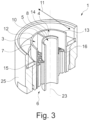
- the Fig. 3 shows a second embodiment of the jet regulator 1 of the Fig. 1 shown sanitary fitting 2 in a longitudinal section.
- the second embodiment of the jet regulator 1 also has a housing 25 which is (essentially) cylindrical and extends along a longitudinal axis 23.
- a first liquid channel 3 of the jet regulator 1 extends from a first inlet opening 12 parallel to the longitudinal axis 23 to the outlet opening 6 of the jet regulator 1.
- a second liquid channel 4 of the jet regulator 1 extends from a second Inlet opening 13 parallel to the longitudinal axis 23 to the outlet opening 6 of the jet regulator 1.
- a third liquid channel 5 of the jet regulator 1 extends from a third inlet opening 14 parallel to the longitudinal axis 23 to the outlet opening 6 of the jet regulator 1.
- the first liquid channel 3 and the second liquid channel 4 are delimited in a radial direction 11, which runs orthogonal to the longitudinal axis 23, by a tubular first partition wall 7 and a tubular second partition wall 8. Furthermore, the first liquid channel 3 and the second liquid channel 4 are separated from one another by a fourth partition wall 10, which extends in the radial direction 11 and parallel to the longitudinal axis 23. The first liquid channel 3 and the second liquid channel 4 therefore each have a ring-segment-shaped cross-section.
- the third liquid channel 5 is limited only by the second partition wall 8, so that the third liquid channel 5 has a circular cross-section.
- a first sieve structure 15 is arranged in the first liquid channel 3, and a second sieve structure 16 is arranged in the second liquid channel 4, which, as in the Fig. 2 shown first embodiment of the jet regulator 1.
- the second embodiment of the jet regulator 1 is like the one shown in the Fig. 2 shown first embodiment of the jet regulator 1 in such a way with the Fig. 1 shown outlet 19 of the sanitary fitting 2, such that the first liquid can be supplied separately to the first liquid channel 3, the second liquid to the second liquid channel 4, and the third liquid to the third liquid channel 5, and the liquids can be conducted separately via the liquid channels 3, 4, 5 to the outlet opening 6. Otherwise, the first embodiment and second embodiment of the jet regulator are identical.
- the present invention prevents different liquids in a jet regulator from influencing each other.
Landscapes
- Health & Medical Sciences (AREA)
- Life Sciences & Earth Sciences (AREA)
- Engineering & Computer Science (AREA)
- Hydrology & Water Resources (AREA)
- Public Health (AREA)
- Water Supply & Treatment (AREA)
- Nozzles (AREA)
Description
Die vorliegende Erfindung betrifft einen Strahlregler für eine Sanitärarmatur sowie eine Sanitärarmatur mit einem entsprechenden Strahlregler. Derartige Sanitärarmaturen dienen insbesondere der bedarfsgerechten Bereitstellung einer Flüssigkeit an einem Spülbecken, Waschbecken oder einer Badewanne.The present invention relates to a jet regulator for a sanitary fitting and to a sanitary fitting with a corresponding jet regulator. Such sanitary fittings are used in particular for the on-demand supply of liquid to a sink, washbasin, or bathtub.
Sanitärarmaturen sind insbesondere Kaltwasser mit einer Kaltwassertemperatur und Warmwasser mit einer Warmwassertemperatur zuführbar. Das Kaltwasser und Warmwasser werden insbesondere mit einer Mischvorrichtung der Sanitärarmatur, beispielsweise nach Art eines Mischventils oder einer Thermostatmischkartusche, zu einem Mischwasser mit einer gewünschten Mischwassertemperatur gemischt, bekannt beispielsweise aus
Aufgabe der Erfindung ist es daher, die mit Bezug auf den Stand der Technik geschilderten Probleme zumindest teilweise zu lösen und insbesondere einen Strahlregler für eine Sanitärarmatur anzugeben, durch den die Flüssigkeiten leitbar sind, ohne dass diese sich geschmacklich beeinflussen. Weiterhin soll eine Sanitärarmatur mit einem Strahlregler angegeben werden, durch den die Flüssigkeiten geleitet werden können, ohne dass diese sich geschmacklich beeinflussen.The object of the invention is therefore to solve at least partially the problems described with reference to the prior art and in particular to provide a jet regulator for a sanitary fitting A flow regulator through which the liquids can be directed without affecting their taste should also be specified. Furthermore, a sanitary fitting with a flow regulator should be specified through which the liquids can be directed without affecting their taste.
Diese Aufgaben werden gelöst mit einem Strahlregler und einer Sanitärarmatur gemäß den Merkmalen der unabhängigen Patentansprüche. Weitere vorteilhafte Ausgestaltungen der Erfindung sind in den abhängigen Patentansprüchen angegeben. Es ist darauf hinzuweisen, dass die in den abhängigen Patentansprüchen einzeln aufgeführten Merkmale in beliebiger technologisch sinnvoller Weise miteinander kombiniert werden können und weitere Ausgestaltungen der Erfindung definieren. Darüber hinaus werden die in den Patentansprüchen angegebenen Merkmale in der Beschreibung näher präzisiert und erläutert, wobei weitere bevorzugte Ausgestaltungen der Erfindung dargestellt werden.These objects are achieved with a jet regulator and a sanitary fitting according to the features of the independent patent claims. Further advantageous embodiments of the invention are specified in the dependent patent claims. It should be noted that the features listed individually in the dependent patent claims can be combined with one another in any technologically expedient manner and define further embodiments of the invention. Furthermore, the features listed in the patent claims are further specified and explained in the description, with further preferred embodiments of the invention being presented.
Hierzu trägt ein Strahlregler für eine Sanitärarmatur bei, die mindestens drei Flüssigkeitskanäle aufweist, denen getrennt voneinander jeweils eine Flüssigkeit zuführbar ist und durch die die einzelnen Flüssigkeiten getrennt voneinander zumindest einer Auslauföffnung des Strahlreglers zuführbar sind.This is achieved by a jet regulator for a sanitary fitting which has at least three liquid channels, each of which can be supplied with a liquid separately and through which the individual liquids can be supplied separately to at least one outlet opening of the jet regulator.
Der Strahlregler ist insbesondere für eine Sanitärarmatur verwendbar bzw. einsetzbar, die der Bereitstellung zumindest drei verschiedener Flüssigkeiten beispielsweise an einer Zapfstelle, einem Spülbecken, einem Waschbecken und/oder einer Badewanne dient. Bei einer ersten Flüssigkeit kann es sich beispielsweise um ein Mischwasser handeln. Das Mischwasser ist durch die Sanitärarmatur insbesondere aus Kaltwasser mit einer Kaltwassertemperatur und Warmwasser mit einer Warmwassertemperatur mischbar. Die Kaltwassertemperatur beträgt insbesondere maximal 25 °C (Celsius), bevorzugt 1 °C bis 25 °C, besonders bevorzugt 5 °C bis 20 °C und/oder die Warmwassertemperatur insbesondere maximal 90 °C, bevorzugt 25 °C bis 90 °C, besonders bevorzugt 55 °C bis 65 °C. Hierzu kann die Sanitärarmatur beispielsweise ein Mischventil aufweisen. Bei einer zweiten Flüssigkeit kann es sich beispielsweise um Heißwasser handeln. Das Heißwasser kann beispielsweise eine Heißwassertemperatur von 95 °C bis 100 °C aufweisen. Hierzu kann die Sanitärarmatur beispielsweise einen Heißwasserbereiter aufweisen oder mit einem Heißwasserbereiter verbunden sein. Bei einer dritten Flüssigkeit kann es sich beispielsweise um karbonisiertes Wasser handeln. Hierzu kann die Sanitärarmatur beispielsweise einen Karbonisierer aufweisen oder mit einem Karbonisierer verbunden sein. Mittels des Karbonisierers ist einer Flüssigkeit insbesondere CO2 zusetzbar.The jet regulator is particularly suitable or applicable for a sanitary fitting that provides at least three different liquids, for example at a tap, a sink, a washbasin, and/or a bathtub. A first liquid can be mixed water, for example. The mixed water can be mixed by the sanitary fitting, in particular from cold water with a cold water temperature and hot water with a hot water temperature. The cold water temperature is in particular a maximum of 25 °C (Celsius), preferably 1 °C to 25 °C, particularly preferably 5 °C to 20 °C, and/or the hot water temperature is in particular a maximum of 90 °C, preferably 25 °C to 90 °C, particularly preferably 55 °C to 65 °C. For this purpose, the sanitary fitting can have a mixing valve, for example. A second liquid can be hot water, for example. The hot water can have a hot water temperature of 95 °C to 100 °C, for example. For this purpose, the sanitary fitting can have a hot water heater, for example, or be connected to a hot water heater. A third liquid can be, for example, Carbonated water. For this purpose, the sanitary fitting can, for example, have a carbonator or be connected to a carbonator. The carbonator can be used to add CO2, in particular, to a liquid.
Die Sanitärarmatur kann ein Armaturengehäuse aufweisen, wobei das Armaturengehäuse zumindest teilweise aus Kunststoff und/oder Metall, wie zum Beispiel Messing oder einer Zinklegierung, bestehen kann. Weiterhin kann das Armaturengehäuse an einem Träger, beispielsweise einer Arbeitsplatte, dem Spülbecken, dem Waschbecken oder der Badewanne, befestigbar sein. Zudem kann das Armaturengehäuse einen (hervorstehenden bzw. abzweigenden) Auslauf aufweisen, der starr oder bewegbar mit dem Armaturengehäuse verbunden ist. Der Auslauf kann zumindest teilweise rohrförmig ausgebildet sein. Weiterhin kann das Armaturengehäuse und/oder der Auslauf eine dekorative äußere Oberfläche aufweisen. Weiterhin kann der Auslauf eine Öffnung aufweisen, die insbesondere einen Innenraum des Auslaufs mit einer Umgebung der Sanitärarmatur verbindet. Der Strahlregler kann insbesondere zumindest teilweise in der Öffnung des Auslaufs angeordnet sein. Beispielsweise kann der Strahlregler ein Gewinde aufweisen, über das der Strahlregler in die Öffnung schraubbar ist. Die zumindest drei Flüssigkeiten sind innerhalb der Sanitärarmatur, des Armaturengehäuses und/oder des Auslaufs insbesondere (über ihren gesamten Strömungsweg) getrennt voneinander führbar.The sanitary fitting may have a fitting housing, wherein the fitting housing may be made at least partially of plastic and/or metal, such as brass or a zinc alloy. Furthermore, the fitting housing may be attachable to a support, for example, a worktop, the sink, the washbasin, or the bathtub. In addition, the fitting housing may have a (protruding or branching) outlet that is rigidly or movably connected to the fitting housing. The outlet may be at least partially tubular. Furthermore, the fitting housing and/or the outlet may have a decorative outer surface. Furthermore, the outlet may have an opening that connects, in particular, an interior of the outlet with an area surrounding the sanitary fitting. The jet regulator may, in particular, be arranged at least partially in the opening of the outlet. For example, the jet regulator may have a thread via which the jet regulator can be screwed into the opening. The at least three liquids can be guided separately from one another within the sanitary fitting, the fitting housing, and/or the outlet, in particular (across their entire flow path).
Der Strahlregler kann beispielsweise nach Art eines Mousseurs, eines Luftsprudlers, einer Düse oder eines Perlators ausgebildet sein. Weiterhin kann der Strahlregler insbesondere dem Vereinheitlichen, Verbreitern und/oder Verlangsamen zumindest eines aus der Sanitärarmatur austretenden Flüssigkeitsstrahls dienen. Zu diesem Zweck kann mittels des Strahlreglers beispielsweise zumindest einer der Flüssigkeiten Luft zumischbar sein. Der Strahlregler kann (im Wesentlichen) zylinderförmig ausgebildet sein und/oder sich entlang einer Längsachse erstrecken. Insbesondere kann der Strahlregler parallel zu der Längsachse eine Länge von 5 mm bis 50 mm und/oder einen Durchmesser (insbesondere orthogonal zu der Längsachse) von 5 mm bis 50 mm aufweisen.The jet regulator can, for example, be designed in the manner of a mousseur, an aerator, a nozzle, or an aerator. Furthermore, the jet regulator can serve, in particular, to standardize, broaden, and/or slow down at least one liquid jet emerging from the sanitary fitting. For this purpose, air can, for example, be admixed with at least one of the liquids using the jet regulator. The jet regulator can be (essentially) cylindrical and/or extend along a longitudinal axis. In particular, the jet regulator can have a length of 5 mm to 50 mm parallel to the longitudinal axis and/or a diameter (in particular orthogonal to the longitudinal axis) of 5 mm to 50 mm.
Der Strahlregler weist mindestens drei getrennte Flüssigkeitskanäle auf, die beispielsweise in Form von getrennten Wasserwegen ausgebildet sein können. Insbesondere weist der Strahlregler für jede der durch die Sanitärarmatur abgebbaren Flüssigkeiten zumindest einen Flüssigkeitskanal oder nur einen Flüssigkeitskanal auf. Die einzelnen Flüssigkeitskanäle können beispielsweise in einem Gehäuse des Strahlreglers ausgebildet sein und/oder führen jeweils insbesondere von einer Einlauföffnung des Strahlreglers bzw. des jeweiligen Flüssigkeitskanals bis zu einer Auslauföffnung des Strahlbildners bzw. des jeweiligen Flüssigkeitskanals. Weiterhin kann zumindest einer der mindestens drei Flüssigkeitskanäle derart ausgestaltet sein, dass bei einem Flüssigkeitsdruck von 3 bar 5 l/min (Liter pro Minute) bis 40 l/min der Flüssigkeit durch den zumindest einen Flüssigkeitskanal fließen. Der Strahlregler ist insbesondere derart mit der Sanitärarmatur verbindbar, dass den mindestens drei Flüssigkeitskanälen die zumindest drei Flüssigkeiten getrennt voneinander zuführbar sind. Durch die mindestens drei Flüssigkeitskanäle sind die mindestens drei Flüssigkeiten zudem getrennt voneinander der Auslauföffnung des Strahlreglers bzw. des jeweiligen Flüssigkeitskanals zuführbar. Hierdurch wird insbesondere gewährleistet, dass die verschiedenen Flüssigkeiten vor Erreichen der Auslauföffnung des Strahlbildners bzw. des jeweiligen Flüssigkeitskanals keinen Kontakt zueinander haben bzw. sich nicht vermischen können. Dies verhindert, dass sich die einzelnen Flüssigkeiten gegenseitig geschmacklich beeinflussen können. Die einzelnen Auslauföffnungen der mindestens drei Flüssigkeitskanäle können zudem gemeinsam die Auslauföffnung des Strahlbildners bilden. Hierzu können die Auslauföffnungen der mindestens drei Flüssigkeitskanäle beispielsweise in Richtung der Längsachse des Strahlreglers mit weniger als 5 mm versetzt zueinander oder an gleicher Position ausgebildet sein.The jet regulator has at least three separate liquid channels, which can be designed, for example, in the form of separate water paths. In particular, the jet regulator has at least one liquid channel or only one liquid channel for each of the liquids that can be discharged through the sanitary fitting. The individual liquid channels can, for example, be formed in a housing of the jet regulator and/or each lead, in particular, from an inlet opening of the jet regulator or the respective liquid channel to an outlet opening of the jet former or the respective liquid channel. Furthermore, at least one of the at least three liquid channels can be designed such that, at a liquid pressure of 3 bar, 5 l/min (liters per minute) to 40 l/min of liquid flow through the at least one liquid channel. The jet regulator can, in particular, be connected to the sanitary fitting in such a way that the at least three liquids can be supplied to the at least three liquid channels separately from one another. The at least three liquid channels also allow the at least three liquids to be fed separately from one another to the outlet opening of the jet regulator or the respective liquid channel. This ensures in particular that the different liquids do not come into contact with one another or cannot mix before reaching the outlet opening of the jet former or the respective liquid channel. This prevents the individual liquids from influencing one another's taste. The individual outlet openings of the at least three liquid channels can also jointly form the outlet opening of the jet former. For this purpose, the outlet openings of the at least three liquid channels can be offset from one another by less than 5 mm in the direction of the longitudinal axis of the jet regulator, for example, or can be designed in the same position.
Zumindest ein Flüssigkeitskanal kann einen kreisförmigen Querschnitt aufweisen. Hierzu kann der zumindest eine Flüssigkeitskanal beispielsweise rohrförmig und/oder nach Art einer Bohrung ausgebildet sein.At least one fluid channel may have a circular cross-section. For this purpose, the at least one fluid channel may be tubular and/or bore-shaped, for example.
Zumindest ein Flüssigkeitskanal kann einen ringförmigen Querschnitt aufweisen. Hierzu kann der zumindest eine Flüssigkeitskanal beispielsweise zwischen zwei rohrförmigen Trennwänden ausgebildet sein. Die beiden rohrförmigen Trennwände können dabei insbesondere konzentrisch zueinander angeordnet sein.At least one fluid channel may have an annular cross-section. For this purpose, the at least one fluid channel may be formed, for example, between two tubular partition walls. The two tubular partition walls may, in particular, be arranged concentrically to one another.
Zumindest ein Flüssigkeitskanal kann einen ringsegmentförmigen Querschnitt aufweisen. Hierzu kann der zumindest eine Flüssigkeitskanal beispielsweise zwischen zwei rohrförmigen und/oder konzentrisch zueinander angeordneten Trennwänden ausgebildet sein, wobei der zumindest eine Flüssigkeitskanal zusätzlich in zumindest einer Umfangsrichtung des Strahlreglers (insbesondere um die Längsachse) durch zumindest eine weitere Trennwand begrenzt ist.At least one liquid channel can have a ring-segment-shaped cross-section. For this purpose, the at least one liquid channel can be formed, for example, between two tubular and/or concentrically arranged partition walls, wherein the at least one liquid channel is additionally delimited in at least one circumferential direction of the jet regulator (in particular around the longitudinal axis) by at least one further partition wall.
Die Flüssigkeitskanäle können durch zumindest eine Trennwand voneinander getrennt sein. Bei der zumindest einen Trennwand kann es sich beispielsweise um einen Teil des Gehäuses des Strahlreglers und/oder separate Komponenten des Strahlreglers handeln.The fluid channels can be separated from each other by at least one partition. The at least one partition can, for example, be part of the jet regulator's housing and/or separate components of the jet regulator.
Die zumindest eine Trennwand kann zumindest teilweise rohrförmig ausgebildet sein.The at least one partition wall can be at least partially tubular.
Die zumindest eine Trennwand kann sich zumindest teilweise in eine radiale Richtung des Strahlreglers erstrecken.The at least one partition wall can extend at least partially in a radial direction of the jet regulator.
Die mindestens drei Flüssigkeitskanäle können von zumindest einer Einlauföffnung zu der zumindest einen Auslauföffnung führen.The at least three liquid channels can lead from at least one inlet opening to the at least one outlet opening.
In zumindest einem der Flüssigkeitskanäle ist eine Siebstruktur angeordnet. Die Siebstruktur weist eine Vielzahl von Kanälen auf, durch die die Flüssigkeit insbesondere parallel zu der Längsachse des Strahlreglers führbar ist. Die Vielzahl von Kanälen sind wabenförmig ausgebildet. Mittels der Siebstruktur kann beispielsweise zumindest eine Trennwand an dem Gehäuse des Strahlreglers und/oder an zumindest einer weiteren Trennwand befestigt sein.A sieve structure is arranged in at least one of the liquid channels. The sieve structure has a plurality of channels through which the liquid can be guided, in particular parallel to the longitudinal axis of the jet regulator. The plurality of channels are honeycomb-shaped. By means of the sieve structure, for example, at least one partition can be attached to the housing of the jet regulator and/or to at least one other partition.
Einem weiteren Aspekt der Erfindung folgend wird auch eine Sanitärarmatur vorgeschlagen, die zumindest ein Armaturengehäuse mit einem Auslauf aufweist, wobei an dem Auslauf zumindest ein erfindungsgemäßer Strahlregler angeordnet ist. Für weitere Einzelheiten zu der Sanitärarmatur wird auf die Beschreibung des Strahlreglers verwiesen.According to a further aspect of the invention, a sanitary fitting is also proposed, which comprises at least one fitting housing with an outlet, wherein at least one jet regulator according to the invention is arranged on the outlet. For further details regarding the sanitary fitting, reference is made to the description of the jet regulator.
Die Erfindung sowie das technische Umfeld werden nachfolgend anhand der Figuren näher erläutert. Es ist darauf hinzuweisen, dass die Figuren besonders bevorzugte Ausführungsvarianten der Erfindung zeigen, diese jedoch nicht darauf beschränkt ist. Dabei sind gleiche Bauteile in den Figuren mit denselben Bezugszeichen versehen. Es zeigen beispielhaft und schematisch:
- Fig. 1:
- eine Sanitärarmatur in einer perspektivischen Darstellung;
- Fig. 2:
- eine erste Ausführungsvariante eines Strahlreglers der Sanitärarmatur in einem Längsschnitt; und
- Fig. 3:
- eine zweite Ausführungsvariante des Strahlreglers der Sanitärarmatur in einem Längsschnitt.
- Fig. 1:
- a sanitary fitting in a perspective view;
- Fig. 2:
- a first embodiment of a jet regulator of the sanitary fitting in a longitudinal section; and
- Fig. 3:
- a second design variant of the jet regulator of the sanitary fitting in a longitudinal section.
Die
Die
Die
Durch die vorliegende Erfindung ist verhinderbar, dass sich verschiedene Flüssigkeiten in einem Strahlregler gegenseitig beeinflussen können.The present invention prevents different liquids in a jet regulator from influencing each other.
- 11
- Strahlregleraerator
- 22
- SanitärarmaturSanitary fitting
- 33
- erster Flüssigkeitskanalfirst fluid channel
- 44
- zweiter Flüssigkeitskanalsecond fluid channel
- 55
- dritter Flüssigkeitskanalthird fluid channel
- 66
- AuslauföffnungOutlet opening
- 77
- erste Trennwandfirst partition wall
- 88
- zweite Trennwandsecond partition wall
- 99
- dritte Trennwandthird partition wall
- 1010
- vierte Trennwandfourth partition wall
- 1111
- radiale Richtungradial direction
- 1212
- erste Einlauföffnungfirst inlet opening
- 1313
- zweiter Einlauföffnungsecond inlet opening
- 1414
- dritte Einlauföffnungthird inlet opening
- 1515
- erste Siebstrukturfirst sieve structure
- 1616
- zweite Siebstruktursecond sieve structure
- 1717
- dritte Siebstrukturthird sieve structure
- 1818
- ArmaturengehäuseValve body
- 1919
- AuslaufOutlet
- 2020
- Öffnungopening
- 2121
- erstes Betätigungselementfirst actuating element
- 2222
- zweites Betätigungselementsecond actuating element
- 2323
- LängsachseLongitudinal axis
- 2424
- KanäleChannels
- 2525
- GehäuseHousing
Claims (9)
- A jet controller (1) for a sanitary fitting (2), wherein the jet controller (1) has at least three fluid channels (3, 4, 5), which can be supplied separately from one another with a respective fluid and through which the individual fluids can be supplied separately from one another to at least one outlet opening (6) of the jet controller (1), characterized in that a sieve structure (15, 16, 17) is arranged in at least one of the fluid channels (3, 4, 5), wherein the sieve structure (15, 16, 17) has a plurality of honeycomb-shaped channels (24) through which the liquid can be guided.
- The jet controller (1) according to claim 1, wherein at least one fluid channel (3, 4, 5) has a circular cross-section.
- The jet controller (1) according to any one of the preceding claims, wherein at least one fluid channel (3, 4, 5) has a ring-shaped cross-section.
- The jet controller (1) according to any one of the preceding claims, wherein at least one fluid channel (3, 4, 5) has a ring segment-shaped cross-section.
- The jet controller (1) according to any one of the preceding claims, wherein the liquid channels (3, 4, 5) are separated from each other by at least one partition wall (7, 8, 9, 10).
- The jet controller (1) according to claim 5, wherein the at least one partition wall (7, 8, 9, 10) is at least partially tubular.
- The jet controller (1) according to claim 5 or 6, wherein the at least one partition wall (7, 8, 9, 10) extends at least partially in a radial direction (11) of the jet controller (1).
- The jet controller (1) according to any one of the preceding claims, wherein the at least three fluid channels (3, 4, 5) lead from at least one inlet opening (12, 13, 14) to the at least one outlet opening (6).
- A sanitary fitting (2), at least comprising a fitting housing (18) with an outlet (19), wherein at least one jet controller (1) according to any one of the preceding claims is arranged on the outlet (19).
Applications Claiming Priority (2)
| Application Number | Priority Date | Filing Date | Title |
|---|---|---|---|
| DE102020105322.3A DE102020105322A1 (en) | 2020-02-28 | 2020-02-28 | Aerator for a sanitary fitting with at least three liquid channels as well as sanitary fitting with a corresponding aerator |
| PCT/EP2021/053461 WO2021170424A1 (en) | 2020-02-28 | 2021-02-12 | Jet controller for a sanitary fitting comprising at least three fluid channels |
Publications (2)
| Publication Number | Publication Date |
|---|---|
| EP4111007A1 EP4111007A1 (en) | 2023-01-04 |
| EP4111007B1 true EP4111007B1 (en) | 2025-06-25 |
Family
ID=74625991
Family Applications (1)
| Application Number | Title | Priority Date | Filing Date |
|---|---|---|---|
| EP21705492.3A Active EP4111007B1 (en) | 2020-02-28 | 2021-02-12 | Jet controller for a sanitary fitting comprising at least three fluid channels |
Country Status (3)
| Country | Link |
|---|---|
| EP (1) | EP4111007B1 (en) |
| DE (1) | DE102020105322A1 (en) |
| WO (1) | WO2021170424A1 (en) |
Families Citing this family (8)
| Publication number | Priority date | Publication date | Assignee | Title |
|---|---|---|---|---|
| WO2024163741A1 (en) * | 2023-02-02 | 2024-08-08 | InSinkErator LLC | Faucet system and method for dispensing near-boiling water |
| USD1056146S1 (en) * | 2023-04-24 | 2024-12-31 | Delta Faucet Company | Faucet spout |
| USD1056144S1 (en) * | 2023-04-24 | 2024-12-31 | Delta Faucet Company | Faucet handle |
| USD1056157S1 (en) * | 2023-04-24 | 2024-12-31 | Delta Faucet Company | Faucet handle |
| USD1056145S1 (en) * | 2023-04-24 | 2024-12-31 | Delta Faucet Company | Faucet |
| USD1056148S1 (en) * | 2023-04-24 | 2024-12-31 | Delta Faucet Company | Faucet |
| USD1056160S1 (en) * | 2023-04-24 | 2024-12-31 | Delta Faucet Company | Faucet spout |
| DE102023123734A1 (en) * | 2023-09-04 | 2025-03-06 | Aquis Systems AG | Device for dispensing water and method for dispensing water |
Citations (1)
| Publication number | Priority date | Publication date | Assignee | Title |
|---|---|---|---|---|
| GB2104625A (en) * | 1981-08-21 | 1983-03-09 | Karrer Weber & Cie Ag | Sanitary fittings |
Family Cites Families (6)
| Publication number | Priority date | Publication date | Assignee | Title |
|---|---|---|---|---|
| WO2006058650A1 (en) | 2004-11-29 | 2006-06-08 | Cornelis Bolderheij Fok | Multi-functional fitting |
| GB2429760B (en) * | 2005-08-08 | 2009-12-09 | Hornbeam Ivy Ltd | Mixer tap |
| DE102014001818B4 (en) | 2014-02-13 | 2025-05-28 | Grohe Ag | Connector for a spout of a sanitary fitting |
| DE102016000766B4 (en) | 2016-01-27 | 2024-04-11 | Neoperl Gmbh | Sanitary outlet piece, sanitary fitting and use of an outlet piece |
| DE202016000472U1 (en) * | 2016-01-27 | 2017-04-28 | Neoperl Gmbh | Sanitary spout, sanitary fitting and use of a spout |
| DE102017101566B3 (en) | 2017-01-26 | 2018-06-28 | Neoperl Gmbh | Hose connection arrangement, use of a hose connection arrangement and sanitary fitting |
-
2020
- 2020-02-28 DE DE102020105322.3A patent/DE102020105322A1/en active Pending
-
2021
- 2021-02-12 WO PCT/EP2021/053461 patent/WO2021170424A1/en not_active Ceased
- 2021-02-12 EP EP21705492.3A patent/EP4111007B1/en active Active
Patent Citations (1)
| Publication number | Priority date | Publication date | Assignee | Title |
|---|---|---|---|---|
| GB2104625A (en) * | 1981-08-21 | 1983-03-09 | Karrer Weber & Cie Ag | Sanitary fittings |
Also Published As
| Publication number | Publication date |
|---|---|
| EP4111007A1 (en) | 2023-01-04 |
| DE102020105322A1 (en) | 2021-09-02 |
| WO2021170424A1 (en) | 2021-09-02 |
Similar Documents
| Publication | Publication Date | Title |
|---|---|---|
| EP4111007B1 (en) | Jet controller for a sanitary fitting comprising at least three fluid channels | |
| DE112012005017B4 (en) | Apparatus for controlling fluid flow in an emergency washing system, apparatus for controlling fluid flow and washing system for providing fluid flow | |
| EP2331755B1 (en) | Regulating device for a water outflow, in particular of sanitary fittings | |
| EP3757301B1 (en) | Beam controller | |
| EP4190984A1 (en) | Jet regulator for a sanitary fitting and sanitary fitting with such a jet regulator | |
| DE112009001469T5 (en) | Shower head for emergency equipment | |
| EP4127333A1 (en) | Outlet element for a drinking water dispensing system and use thereof, drinking water dispensing system comprising such an outlet element, and method for dispensing drinking water from such a drinking water dispensing system | |
| DE69838907T2 (en) | MULTI-STEAM SHOWER WITH AIR CONNECTION | |
| DE69005267T2 (en) | Shower unit. | |
| DE102014001818B4 (en) | Connector for a spout of a sanitary fitting | |
| WO2004098758A1 (en) | Dispersing device | |
| EP1359260A2 (en) | Shower head | |
| DE102021101779A1 (en) | Aerator for a sanitary fitting and sanitary fitting with a corresponding aerator | |
| WO2022194505A1 (en) | Fluidic outflow unit and associated uses | |
| EP3546421B1 (en) | Dispensing device comprising a nozzle insert with a baffle | |
| DE102020124931A1 (en) | Sanitary fitting with at least one first liquid outlet and at least one second liquid outlet | |
| WO2020182491A1 (en) | Sanitary shower comprising a jet-forming element with at least one duckbill valve | |
| EP4249691B1 (en) | Sanitary fitting with a hose | |
| DE3335756A1 (en) | Hand shower-head | |
| DE102022105239A1 (en) | Aerator for a sanitary fitting | |
| DE102022106361A1 (en) | Plumbing fitting with a hose | |
| DE68904817T2 (en) | DISTRIBUTION DEVICE FOR SHOWERS AND HYDROMASSAGE. | |
| EP4025349A1 (en) | Sanitary shower with a pulsation disc | |
| DE102021106865A1 (en) | Fluidic outflow unit and associated uses | |
| DE102021106866A1 (en) | Fluidic outflow unit and associated uses |
Legal Events
| Date | Code | Title | Description |
|---|---|---|---|
| STAA | Information on the status of an ep patent application or granted ep patent |
Free format text: STATUS: UNKNOWN |
|
| STAA | Information on the status of an ep patent application or granted ep patent |
Free format text: STATUS: THE INTERNATIONAL PUBLICATION HAS BEEN MADE |
|
| PUAI | Public reference made under article 153(3) epc to a published international application that has entered the european phase |
Free format text: ORIGINAL CODE: 0009012 |
|
| STAA | Information on the status of an ep patent application or granted ep patent |
Free format text: STATUS: REQUEST FOR EXAMINATION WAS MADE |
|
| 17P | Request for examination filed |
Effective date: 20220902 |
|
| AK | Designated contracting states |
Kind code of ref document: A1 Designated state(s): AL AT BE BG CH CY CZ DE DK EE ES FI FR GB GR HR HU IE IS IT LI LT LU LV MC MK MT NL NO PL PT RO RS SE SI SK SM TR |
|
| DAV | Request for validation of the european patent (deleted) | ||
| DAX | Request for extension of the european patent (deleted) | ||
| STAA | Information on the status of an ep patent application or granted ep patent |
Free format text: STATUS: EXAMINATION IS IN PROGRESS |
|
| 17Q | First examination report despatched |
Effective date: 20240605 |
|
| GRAP | Despatch of communication of intention to grant a patent |
Free format text: ORIGINAL CODE: EPIDOSNIGR1 |
|
| STAA | Information on the status of an ep patent application or granted ep patent |
Free format text: STATUS: GRANT OF PATENT IS INTENDED |
|
| INTG | Intention to grant announced |
Effective date: 20250311 |
|
| GRAS | Grant fee paid |
Free format text: ORIGINAL CODE: EPIDOSNIGR3 |
|
| GRAA | (expected) grant |
Free format text: ORIGINAL CODE: 0009210 |
|
| STAA | Information on the status of an ep patent application or granted ep patent |
Free format text: STATUS: THE PATENT HAS BEEN GRANTED |
|
| AK | Designated contracting states |
Kind code of ref document: B1 Designated state(s): AL AT BE BG CH CY CZ DE DK EE ES FI FR GB GR HR HU IE IS IT LI LT LU LV MC MK MT NL NO PL PT RO RS SE SI SK SM TR |
|
| REG | Reference to a national code |
Ref country code: GB Ref legal event code: FG4D Free format text: NOT ENGLISH |
|
| REG | Reference to a national code |
Ref country code: CH Ref legal event code: EP |
|
| REG | Reference to a national code |
Ref country code: DE Ref legal event code: R096 Ref document number: 502021007841 Country of ref document: DE |
|
| REG | Reference to a national code |
Ref country code: CH Ref legal event code: EP |
|
| REG | Reference to a national code |
Ref country code: IE Ref legal event code: FG4D Free format text: LANGUAGE OF EP DOCUMENT: GERMAN |
|
| P01 | Opt-out of the competence of the unified patent court (upc) registered |
Free format text: CASE NUMBER: UPC_APP_0553_4111007/2025 Effective date: 20250718 |
|
| PG25 | Lapsed in a contracting state [announced via postgrant information from national office to epo] |
Ref country code: FI Free format text: LAPSE BECAUSE OF FAILURE TO SUBMIT A TRANSLATION OF THE DESCRIPTION OR TO PAY THE FEE WITHIN THE PRESCRIBED TIME-LIMIT Effective date: 20250625 |
|
| REG | Reference to a national code |
Ref country code: LT Ref legal event code: MG9D |
|
| PG25 | Lapsed in a contracting state [announced via postgrant information from national office to epo] |
Ref country code: NO Free format text: LAPSE BECAUSE OF FAILURE TO SUBMIT A TRANSLATION OF THE DESCRIPTION OR TO PAY THE FEE WITHIN THE PRESCRIBED TIME-LIMIT Effective date: 20250925 Ref country code: GR Free format text: LAPSE BECAUSE OF FAILURE TO SUBMIT A TRANSLATION OF THE DESCRIPTION OR TO PAY THE FEE WITHIN THE PRESCRIBED TIME-LIMIT Effective date: 20250926 |
|
| PG25 | Lapsed in a contracting state [announced via postgrant information from national office to epo] |
Ref country code: BG Free format text: LAPSE BECAUSE OF FAILURE TO SUBMIT A TRANSLATION OF THE DESCRIPTION OR TO PAY THE FEE WITHIN THE PRESCRIBED TIME-LIMIT Effective date: 20250625 |
|
| PG25 | Lapsed in a contracting state [announced via postgrant information from national office to epo] |
Ref country code: HR Free format text: LAPSE BECAUSE OF FAILURE TO SUBMIT A TRANSLATION OF THE DESCRIPTION OR TO PAY THE FEE WITHIN THE PRESCRIBED TIME-LIMIT Effective date: 20250625 |
|
| PG25 | Lapsed in a contracting state [announced via postgrant information from national office to epo] |
Ref country code: RS Free format text: LAPSE BECAUSE OF FAILURE TO SUBMIT A TRANSLATION OF THE DESCRIPTION OR TO PAY THE FEE WITHIN THE PRESCRIBED TIME-LIMIT Effective date: 20250925 |
|
| PG25 | Lapsed in a contracting state [announced via postgrant information from national office to epo] |
Ref country code: LV Free format text: LAPSE BECAUSE OF FAILURE TO SUBMIT A TRANSLATION OF THE DESCRIPTION OR TO PAY THE FEE WITHIN THE PRESCRIBED TIME-LIMIT Effective date: 20250625 |
|
| REG | Reference to a national code |
Ref country code: NL Ref legal event code: MP Effective date: 20250625 |
|
| PG25 | Lapsed in a contracting state [announced via postgrant information from national office to epo] |
Ref country code: NL Free format text: LAPSE BECAUSE OF FAILURE TO SUBMIT A TRANSLATION OF THE DESCRIPTION OR TO PAY THE FEE WITHIN THE PRESCRIBED TIME-LIMIT Effective date: 20250625 |
|
| PG25 | Lapsed in a contracting state [announced via postgrant information from national office to epo] |
Ref country code: PT Free format text: LAPSE BECAUSE OF FAILURE TO SUBMIT A TRANSLATION OF THE DESCRIPTION OR TO PAY THE FEE WITHIN THE PRESCRIBED TIME-LIMIT Effective date: 20251027 |
|
| PG25 | Lapsed in a contracting state [announced via postgrant information from national office to epo] |
Ref country code: IS Free format text: LAPSE BECAUSE OF FAILURE TO SUBMIT A TRANSLATION OF THE DESCRIPTION OR TO PAY THE FEE WITHIN THE PRESCRIBED TIME-LIMIT Effective date: 20251025 |
|
| PG25 | Lapsed in a contracting state [announced via postgrant information from national office to epo] |
Ref country code: SM Free format text: LAPSE BECAUSE OF FAILURE TO SUBMIT A TRANSLATION OF THE DESCRIPTION OR TO PAY THE FEE WITHIN THE PRESCRIBED TIME-LIMIT Effective date: 20250625 |
|
| PG25 | Lapsed in a contracting state [announced via postgrant information from national office to epo] |
Ref country code: CZ Free format text: LAPSE BECAUSE OF FAILURE TO SUBMIT A TRANSLATION OF THE DESCRIPTION OR TO PAY THE FEE WITHIN THE PRESCRIBED TIME-LIMIT Effective date: 20250625 |
|
| PG25 | Lapsed in a contracting state [announced via postgrant information from national office to epo] |
Ref country code: PL Free format text: LAPSE BECAUSE OF FAILURE TO SUBMIT A TRANSLATION OF THE DESCRIPTION OR TO PAY THE FEE WITHIN THE PRESCRIBED TIME-LIMIT Effective date: 20250625 |
|
| PG25 | Lapsed in a contracting state [announced via postgrant information from national office to epo] |
Ref country code: EE Free format text: LAPSE BECAUSE OF FAILURE TO SUBMIT A TRANSLATION OF THE DESCRIPTION OR TO PAY THE FEE WITHIN THE PRESCRIBED TIME-LIMIT Effective date: 20250625 |
|
| PG25 | Lapsed in a contracting state [announced via postgrant information from national office to epo] |
Ref country code: SK Free format text: LAPSE BECAUSE OF FAILURE TO SUBMIT A TRANSLATION OF THE DESCRIPTION OR TO PAY THE FEE WITHIN THE PRESCRIBED TIME-LIMIT Effective date: 20250625 |
|
| PG25 | Lapsed in a contracting state [announced via postgrant information from national office to epo] |
Ref country code: ES Free format text: LAPSE BECAUSE OF FAILURE TO SUBMIT A TRANSLATION OF THE DESCRIPTION OR TO PAY THE FEE WITHIN THE PRESCRIBED TIME-LIMIT Effective date: 20250625 |