EP4111007B1 - Régulateur de jet pour appareil sanitaire comprenant au moins trois canaux de fluide - Google Patents
Régulateur de jet pour appareil sanitaire comprenant au moins trois canaux de fluide Download PDFInfo
- Publication number
- EP4111007B1 EP4111007B1 EP21705492.3A EP21705492A EP4111007B1 EP 4111007 B1 EP4111007 B1 EP 4111007B1 EP 21705492 A EP21705492 A EP 21705492A EP 4111007 B1 EP4111007 B1 EP 4111007B1
- Authority
- EP
- European Patent Office
- Prior art keywords
- liquid
- jet regulator
- jet controller
- sanitary fitting
- jet
- Prior art date
- Legal status (The legal status is an assumption and is not a legal conclusion. Google has not performed a legal analysis and makes no representation as to the accuracy of the status listed.)
- Active
Links
Images

Classifications
-
- E—FIXED CONSTRUCTIONS
- E03—WATER SUPPLY; SEWERAGE
- E03C—DOMESTIC PLUMBING INSTALLATIONS FOR FRESH WATER OR WASTE WATER; SINKS
- E03C1/00—Domestic plumbing installations for fresh water or waste water; Sinks
- E03C1/02—Plumbing installations for fresh water
- E03C1/08—Jet regulators or jet guides, e.g. anti-splash devices
- E03C1/084—Jet regulators with aerating means
-
- E—FIXED CONSTRUCTIONS
- E03—WATER SUPPLY; SEWERAGE
- E03C—DOMESTIC PLUMBING INSTALLATIONS FOR FRESH WATER OR WASTE WATER; SINKS
- E03C1/00—Domestic plumbing installations for fresh water or waste water; Sinks
- E03C1/02—Plumbing installations for fresh water
- E03C1/04—Water-basin installations specially adapted to wash-basins or baths
- E03C1/0404—Constructional or functional features of the spout
Definitions
- the present invention relates to a jet regulator for a sanitary fitting and to a sanitary fitting with a corresponding jet regulator.
- Such sanitary fittings are used in particular for the on-demand supply of liquid to a sink, washbasin, or bathtub.
- the various liquids leave the sanitary fittings via a (common) jet regulator, which in particular standardizes the liquid jet emerging from the sanitary fittings, known for example from DE 20 2016 000 472 U1
- a (common) jet regulator which in particular standardizes the liquid jet emerging from the sanitary fittings, known for example from DE 20 2016 000 472 U1
- the different liquids flow through the same areas of the aerator, which can influence each other (for example, in terms of taste). Furthermore, this can lead to hygiene problems.
- a jet regulator for a sanitary fitting which has at least three liquid channels, each of which can be supplied with a liquid separately and through which the individual liquids can be supplied separately to at least one outlet opening of the jet regulator.
- the jet regulator is particularly suitable or applicable for a sanitary fitting that provides at least three different liquids, for example at a tap, a sink, a washbasin, and/or a bathtub.
- a first liquid can be mixed water, for example.
- the mixed water can be mixed by the sanitary fitting, in particular from cold water with a cold water temperature and hot water with a hot water temperature.
- the cold water temperature is in particular a maximum of 25 °C (Celsius), preferably 1 °C to 25 °C, particularly preferably 5 °C to 20 °C
- the hot water temperature is in particular a maximum of 90 °C, preferably 25 °C to 90 °C, particularly preferably 55 °C to 65 °C.
- the sanitary fitting can have a mixing valve, for example.
- a second liquid can be hot water, for example.
- the hot water can have a hot water temperature of 95 °C to 100 °C, for example.
- the sanitary fitting can have a hot water heater, for example, or be connected to a hot water heater.
- a third liquid can be, for example, Carbonated water.
- the sanitary fitting can, for example, have a carbonator or be connected to a carbonator. The carbonator can be used to add CO2, in particular, to a liquid.
- the sanitary fitting may have a fitting housing, wherein the fitting housing may be made at least partially of plastic and/or metal, such as brass or a zinc alloy. Furthermore, the fitting housing may be attachable to a support, for example, a worktop, the sink, the washbasin, or the bathtub.
- the fitting housing may have a (protruding or branching) outlet that is rigidly or movably connected to the fitting housing.
- the outlet may be at least partially tubular.
- the fitting housing and/or the outlet may have a decorative outer surface.
- the outlet may have an opening that connects, in particular, an interior of the outlet with an area surrounding the sanitary fitting.
- the jet regulator may, in particular, be arranged at least partially in the opening of the outlet.
- the jet regulator can, for example, be designed in the manner of a mousseur, an aerator, a nozzle, or an aerator. Furthermore, the jet regulator can serve, in particular, to standardize, broaden, and/or slow down at least one liquid jet emerging from the sanitary fitting. For this purpose, air can, for example, be admixed with at least one of the liquids using the jet regulator.
- the jet regulator can be (essentially) cylindrical and/or extend along a longitudinal axis. In particular, the jet regulator can have a length of 5 mm to 50 mm parallel to the longitudinal axis and/or a diameter (in particular orthogonal to the longitudinal axis) of 5 mm to 50 mm.
- the jet regulator has at least three separate liquid channels, which can be designed, for example, in the form of separate water paths.
- the jet regulator has at least one liquid channel or only one liquid channel for each of the liquids that can be discharged through the sanitary fitting.
- the individual liquid channels can, for example, be formed in a housing of the jet regulator and/or each lead, in particular, from an inlet opening of the jet regulator or the respective liquid channel to an outlet opening of the jet former or the respective liquid channel.
- at least one of the at least three liquid channels can be designed such that, at a liquid pressure of 3 bar, 5 l/min (liters per minute) to 40 l/min of liquid flow through the at least one liquid channel.
- the jet regulator can, in particular, be connected to the sanitary fitting in such a way that the at least three liquids can be supplied to the at least three liquid channels separately from one another.
- the at least three liquid channels also allow the at least three liquids to be fed separately from one another to the outlet opening of the jet regulator or the respective liquid channel. This ensures in particular that the different liquids do not come into contact with one another or cannot mix before reaching the outlet opening of the jet former or the respective liquid channel. This prevents the individual liquids from influencing one another's taste.
- the individual outlet openings of the at least three liquid channels can also jointly form the outlet opening of the jet former.
- the outlet openings of the at least three liquid channels can be offset from one another by less than 5 mm in the direction of the longitudinal axis of the jet regulator, for example, or can be designed in the same position.
- At least one liquid channel can have a ring-segment-shaped cross-section.
- the at least one liquid channel can be formed, for example, between two tubular and/or concentrically arranged partition walls, wherein the at least one liquid channel is additionally delimited in at least one circumferential direction of the jet regulator (in particular around the longitudinal axis) by at least one further partition wall.
- the at least one partition wall can extend at least partially in a radial direction of the jet regulator.
- a sieve structure is arranged in at least one of the liquid channels.
- the sieve structure has a plurality of channels through which the liquid can be guided, in particular parallel to the longitudinal axis of the jet regulator.
- the plurality of channels are honeycomb-shaped.
- at least one partition can be attached to the housing of the jet regulator and/or to at least one other partition.
- a sanitary fitting which comprises at least one fitting housing with an outlet, wherein at least one jet regulator according to the invention is arranged on the outlet.
- at least one jet regulator according to the invention is arranged on the outlet.
- the Fig. 1 shows a sanitary fitting 2 in a perspective view.
- the sanitary fitting 2 has a fitting housing 18 with an outlet 19.
- the fitting housing 18 can be attached to a support (not shown here), such as a sink.
- a jet regulator 1 is arranged in an opening 20 of the outlet 19, which in the embodiment of the sanitary fitting 2 shown here is screwed to the outlet 19.
- Three different liquids can be supplied to the jet regulator 1, which are distributed via three liquid channels 3, 4, 5 of the jet regulator 1. can be guided separately from one another to an outlet opening 6 of the jet regulator 1.
- the jet regulator 1 has a first actuating element 21 in the form of an actuating lever, by means of which the dispensing of a first liquid can be controlled.
- the first liquid is mixed water that can be mixed from cold water and hot water by means of a mixing cartridge (not shown here) of the sanitary fitting 2.
- the mixing cartridge can be actuated by the first actuating element 21.
- a mixed water temperature of the mixed water and a dispensing quantity of the mixed water can be adjusted by the first actuating element 21.
- the jet regulator 1 has a second actuating element 22, by means of which the dispensing of a second liquid and a third liquid can be controlled.
- the second liquid here is hot water and the third liquid is carbonated water.
- the Fig. 2 shows a first embodiment of the jet regulator 1 of the Fig. 1 shown sanitary fitting 2 in a longitudinal section.
- the jet regulator 1 has a housing 25 which is (essentially) cylindrical and extends along a longitudinal axis 23.
- a first liquid channel 3 of the jet regulator 1 extends from a first inlet opening 12 parallel to the longitudinal axis 23 to the outlet opening 6 of the jet regulator 1.
- a second liquid channel 4 of the jet regulator 1 extends from a second inlet opening 13 parallel to the longitudinal axis 23 to the outlet opening 6 of the jet regulator 1.
- a third liquid channel 5 of the jet regulator 1 extends from a third inlet opening 14 parallel to the longitudinal axis 23 to the outlet opening 6 of the jet regulator 1.
- the sieve structures 15, 16, 17 here have a plurality of honeycomb-shaped channels 24 running parallel to the longitudinal axis 23.
- the jet regulator 1 is thus provided with the Fig. 1 shown outlet 19 of the sanitary fitting 2, such that the first liquid can be fed to the first liquid channel 3, the second liquid to the second liquid channel 4 and the third liquid to the third liquid channel 5 separately from one another and the liquids can be guided separately from one another via the liquid channels 3, 4, 5 to the outlet opening 6.
- the liquids can be dispensed via the outlet opening 6 of the jet regulator 1 without the liquids having to be previously contained in the jet regulator 1 and/or in the Fig. 1 shown sanitary fitting 2.
- the jet regulator 1 can have an external thread not shown here.
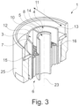
- the Fig. 3 shows a second embodiment of the jet regulator 1 of the Fig. 1 shown sanitary fitting 2 in a longitudinal section.
- the second embodiment of the jet regulator 1 also has a housing 25 which is (essentially) cylindrical and extends along a longitudinal axis 23.
- a first liquid channel 3 of the jet regulator 1 extends from a first inlet opening 12 parallel to the longitudinal axis 23 to the outlet opening 6 of the jet regulator 1.
- a second liquid channel 4 of the jet regulator 1 extends from a second Inlet opening 13 parallel to the longitudinal axis 23 to the outlet opening 6 of the jet regulator 1.
- a third liquid channel 5 of the jet regulator 1 extends from a third inlet opening 14 parallel to the longitudinal axis 23 to the outlet opening 6 of the jet regulator 1.
- the first liquid channel 3 and the second liquid channel 4 are delimited in a radial direction 11, which runs orthogonal to the longitudinal axis 23, by a tubular first partition wall 7 and a tubular second partition wall 8. Furthermore, the first liquid channel 3 and the second liquid channel 4 are separated from one another by a fourth partition wall 10, which extends in the radial direction 11 and parallel to the longitudinal axis 23. The first liquid channel 3 and the second liquid channel 4 therefore each have a ring-segment-shaped cross-section.
- the third liquid channel 5 is limited only by the second partition wall 8, so that the third liquid channel 5 has a circular cross-section.
- a first sieve structure 15 is arranged in the first liquid channel 3, and a second sieve structure 16 is arranged in the second liquid channel 4, which, as in the Fig. 2 shown first embodiment of the jet regulator 1.
- the second embodiment of the jet regulator 1 is like the one shown in the Fig. 2 shown first embodiment of the jet regulator 1 in such a way with the Fig. 1 shown outlet 19 of the sanitary fitting 2, such that the first liquid can be supplied separately to the first liquid channel 3, the second liquid to the second liquid channel 4, and the third liquid to the third liquid channel 5, and the liquids can be conducted separately via the liquid channels 3, 4, 5 to the outlet opening 6. Otherwise, the first embodiment and second embodiment of the jet regulator are identical.
- the present invention prevents different liquids in a jet regulator from influencing each other.
Landscapes
- Health & Medical Sciences (AREA)
- Life Sciences & Earth Sciences (AREA)
- Engineering & Computer Science (AREA)
- Hydrology & Water Resources (AREA)
- Public Health (AREA)
- Water Supply & Treatment (AREA)
- Nozzles (AREA)
Claims (9)
- Régulateur de jet (1), destiné à une robinetterie sanitaire (2), le régulateur de jet (1) comportant au moins trois canaux à liquide (3, 4, 5), vers lesquels séparément l'un de l'autre peut être alimenté un liquide et à travers lesquels les liquides individuels peuvent être alimentés séparément les uns des autres vers au moins un orifice d'écoulement (6) du régulateur de jets (1), caractérisé en ce que dans au moins l'un des canaux à liquide (3, 4, 5) est placée une structure de tamisage (15, 16, 17), la structure de tamisage (15, 16, 17) comportant une pluralité de canaux (24) en forme d'alvéoles, à travers lesquels le liquide peut être conduit.
- Régulateur de jet (1) selon la revendication 1 du brevet, au moins un canal à liquide (3, 4, 5) présentant une section transversale de forme circulaire.
- Régulateur de jet (1) selon l'une quelconque des revendications précédentes du brevet, au moins un canal à liquide (3, 4, 5) présentant une section transversale de forme annulaire.
- Régulateur de jet (1) selon l'une quelconque des revendications précédentes du brevet, au moins un canal à liquide (3, 4, 5) présentant une section transversale en forme de segment annulaire.
- Régulateur de jet (1) selon l'une quelconque des revendications précédentes du brevet, les canaux à liquide (3, 4, 5) étant séparés les uns des autres par au moins une paroi de séparation (7, 8, 9, 10).
- Régulateur de jet (1) selon la revendication 5, l'au moins une paroi de séparation (7, 8, 9, 10) étant conçue au moins en partie de forme tubulaire.
- Régulateur de jet (1) selon la revendication 5 ou 6, l'au moins une paroi de séparation (7, 8, 9, 10) s'étendant au moins en partie dans une direction radiale (11) du régulateur de jet (1).
- Régulateur de jet (1) selon l'une quelconque des revendications précédentes du brevet, les au moins trois canaux à liquide (3, 4, 5) conduisant d'au moins un orifice d'entrée (12, 13, 14) vers l'au moins un orifice d'écoulement (6).
- Robinetterie sanitaire (2), comportant au moins un corps de robinetterie (18) pourvu d'un écoulement (19), sur l'écoulement (19) étant placé au moins un régulateur de jet (1) selon l'une quelconque des revendications précédentes.
Applications Claiming Priority (2)
| Application Number | Priority Date | Filing Date | Title |
|---|---|---|---|
| DE102020105322.3A DE102020105322A1 (de) | 2020-02-28 | 2020-02-28 | Strahlregler für eine Sanitärarmatur mit mindestens drei Flüssigkeitskanälen sowie Sanitärarmatur mit einem entsprechenden Strahlregler |
| PCT/EP2021/053461 WO2021170424A1 (fr) | 2020-02-28 | 2021-02-12 | Régulateur de jet pour appareil sanitaire comprenant au moins trois canaux de fluide |
Publications (2)
| Publication Number | Publication Date |
|---|---|
| EP4111007A1 EP4111007A1 (fr) | 2023-01-04 |
| EP4111007B1 true EP4111007B1 (fr) | 2025-06-25 |
Family
ID=74625991
Family Applications (1)
| Application Number | Title | Priority Date | Filing Date |
|---|---|---|---|
| EP21705492.3A Active EP4111007B1 (fr) | 2020-02-28 | 2021-02-12 | Régulateur de jet pour appareil sanitaire comprenant au moins trois canaux de fluide |
Country Status (3)
| Country | Link |
|---|---|
| EP (1) | EP4111007B1 (fr) |
| DE (1) | DE102020105322A1 (fr) |
| WO (1) | WO2021170424A1 (fr) |
Families Citing this family (8)
| Publication number | Priority date | Publication date | Assignee | Title |
|---|---|---|---|---|
| WO2024163741A1 (fr) * | 2023-02-02 | 2024-08-08 | InSinkErator LLC | Système de robinet et procédé de distribution d'eau proche de l'ébullition |
| USD1056146S1 (en) * | 2023-04-24 | 2024-12-31 | Delta Faucet Company | Faucet spout |
| USD1056144S1 (en) * | 2023-04-24 | 2024-12-31 | Delta Faucet Company | Faucet handle |
| USD1056157S1 (en) * | 2023-04-24 | 2024-12-31 | Delta Faucet Company | Faucet handle |
| USD1056145S1 (en) * | 2023-04-24 | 2024-12-31 | Delta Faucet Company | Faucet |
| USD1056148S1 (en) * | 2023-04-24 | 2024-12-31 | Delta Faucet Company | Faucet |
| USD1056160S1 (en) * | 2023-04-24 | 2024-12-31 | Delta Faucet Company | Faucet spout |
| DE102023123734A1 (de) * | 2023-09-04 | 2025-03-06 | Aquis Systems AG | Vorrichtung zur Wasserausgabe und Verfahren zur Ausgabe von Wasser |
Citations (1)
| Publication number | Priority date | Publication date | Assignee | Title |
|---|---|---|---|---|
| GB2104625A (en) * | 1981-08-21 | 1983-03-09 | Karrer Weber & Cie Ag | Sanitary fittings |
Family Cites Families (6)
| Publication number | Priority date | Publication date | Assignee | Title |
|---|---|---|---|---|
| WO2006058650A1 (fr) | 2004-11-29 | 2006-06-08 | Cornelis Bolderheij Fok | Robinetterie multifonction |
| GB2429760B (en) * | 2005-08-08 | 2009-12-09 | Hornbeam Ivy Ltd | Mixer tap |
| DE102014001818B4 (de) | 2014-02-13 | 2025-05-28 | Grohe Ag | Anschlussstück für einen Auslauf einer Sanitärarmatur |
| DE102016000766B4 (de) | 2016-01-27 | 2024-04-11 | Neoperl Gmbh | Sanitäres Auslaufstück, Sanitärarmatur und Verwendung eines Auslaufstücks |
| DE202016000472U1 (de) * | 2016-01-27 | 2017-04-28 | Neoperl Gmbh | Sanitäres Auslaufstück, Sanitärarmatur und Verwendung eines Auslaufstücks |
| DE102017101566B3 (de) | 2017-01-26 | 2018-06-28 | Neoperl Gmbh | Schlauchanschlussanordnung, Verwendung einer Schlauchanschlussanordnung und Sanitärarmatur |
-
2020
- 2020-02-28 DE DE102020105322.3A patent/DE102020105322A1/de active Pending
-
2021
- 2021-02-12 WO PCT/EP2021/053461 patent/WO2021170424A1/fr not_active Ceased
- 2021-02-12 EP EP21705492.3A patent/EP4111007B1/fr active Active
Patent Citations (1)
| Publication number | Priority date | Publication date | Assignee | Title |
|---|---|---|---|---|
| GB2104625A (en) * | 1981-08-21 | 1983-03-09 | Karrer Weber & Cie Ag | Sanitary fittings |
Also Published As
| Publication number | Publication date |
|---|---|
| EP4111007A1 (fr) | 2023-01-04 |
| DE102020105322A1 (de) | 2021-09-02 |
| WO2021170424A1 (fr) | 2021-09-02 |
Similar Documents
| Publication | Publication Date | Title |
|---|---|---|
| EP4111007B1 (fr) | Régulateur de jet pour appareil sanitaire comprenant au moins trois canaux de fluide | |
| DE112012005017B4 (de) | Vorrichtung zum Steuern einer Fluid-Strömung in einem Notfall-Waschsystem, Vorrichtung zum Steuern einer Fluid-Strömung und Waschsystem zum Liefern einer Fluid-Strömung | |
| EP2331755B1 (fr) | Dispositif de régulation pour orifice d'écoulement d'eau, en particulier d'une plomberie sanitaire | |
| EP3757301B1 (fr) | Régulateur de jet | |
| EP4190984A1 (fr) | Régulateur de jet pour une armature sanitaire et armature sanitaire dotée d'un tel régulateur de jet | |
| DE112009001469T5 (de) | Duschkopf für Notfalleinrichtung | |
| EP4127333A1 (fr) | Élément d'écoulement pour un système de distribution d'eau potable et son utilisation, système de distribution d'eau potable doté d'un tel élément d'écoulement, procédé pour soutirer de l'eau potable d'un tel système de distribution d'eau potable | |
| DE69838907T2 (de) | Mehrfachstrahldusche mit luftzumischung | |
| DE69005267T2 (de) | Brauseeinheit. | |
| DE102014001818B4 (de) | Anschlussstück für einen Auslauf einer Sanitärarmatur | |
| WO2004098758A1 (fr) | Disperseur | |
| EP1359260A2 (fr) | Pomme de douche | |
| DE102021101779A1 (de) | Strahlregler für eine Sanitärarmatur sowie Sanitärarmatur mit einem entsprechenden Strahlregler | |
| WO2022194505A1 (fr) | Unité de sortie fluidique et utilisations associées | |
| EP3546421B1 (fr) | Dispositif de distribution comportant un insert de buse doté d'une paroi d'impact | |
| DE102020124931A1 (de) | Sanitärarmatur mit zumindest einem ersten Flüssigkeitsauslass und zumindest einem zweiten Flüssigkeitsauslass | |
| WO2020182491A1 (fr) | Douche sanitaire présentant un dispositif de formation de jets pourvu d'au moins une valve en bec de canard | |
| EP4249691B1 (fr) | Robinetterie sanitaire dotée d'un tuyau flexible | |
| DE3335756A1 (de) | Handbrause | |
| DE102022105239A1 (de) | Strahlregler für eine Sanitärarmatur | |
| DE102022106361A1 (de) | Sanitärarmatur mit einem Schlauch | |
| DE68904817T2 (de) | Verteilvorrichtung fuer brausen und hydromassage. | |
| EP4025349A1 (fr) | Douche sanitaire dotée d'un disque de pulsation | |
| DE102021106865A1 (de) | Fluidische Ausflusseinheit sowie zugehörige Verwendungen | |
| DE102021106866A1 (de) | Fluidische Ausflusseinheit sowie zugehörige Verwendungen |
Legal Events
| Date | Code | Title | Description |
|---|---|---|---|
| STAA | Information on the status of an ep patent application or granted ep patent |
Free format text: STATUS: UNKNOWN |
|
| STAA | Information on the status of an ep patent application or granted ep patent |
Free format text: STATUS: THE INTERNATIONAL PUBLICATION HAS BEEN MADE |
|
| PUAI | Public reference made under article 153(3) epc to a published international application that has entered the european phase |
Free format text: ORIGINAL CODE: 0009012 |
|
| STAA | Information on the status of an ep patent application or granted ep patent |
Free format text: STATUS: REQUEST FOR EXAMINATION WAS MADE |
|
| 17P | Request for examination filed |
Effective date: 20220902 |
|
| AK | Designated contracting states |
Kind code of ref document: A1 Designated state(s): AL AT BE BG CH CY CZ DE DK EE ES FI FR GB GR HR HU IE IS IT LI LT LU LV MC MK MT NL NO PL PT RO RS SE SI SK SM TR |
|
| DAV | Request for validation of the european patent (deleted) | ||
| DAX | Request for extension of the european patent (deleted) | ||
| STAA | Information on the status of an ep patent application or granted ep patent |
Free format text: STATUS: EXAMINATION IS IN PROGRESS |
|
| 17Q | First examination report despatched |
Effective date: 20240605 |
|
| GRAP | Despatch of communication of intention to grant a patent |
Free format text: ORIGINAL CODE: EPIDOSNIGR1 |
|
| STAA | Information on the status of an ep patent application or granted ep patent |
Free format text: STATUS: GRANT OF PATENT IS INTENDED |
|
| INTG | Intention to grant announced |
Effective date: 20250311 |
|
| GRAS | Grant fee paid |
Free format text: ORIGINAL CODE: EPIDOSNIGR3 |
|
| GRAA | (expected) grant |
Free format text: ORIGINAL CODE: 0009210 |
|
| STAA | Information on the status of an ep patent application or granted ep patent |
Free format text: STATUS: THE PATENT HAS BEEN GRANTED |
|
| AK | Designated contracting states |
Kind code of ref document: B1 Designated state(s): AL AT BE BG CH CY CZ DE DK EE ES FI FR GB GR HR HU IE IS IT LI LT LU LV MC MK MT NL NO PL PT RO RS SE SI SK SM TR |
|
| REG | Reference to a national code |
Ref country code: GB Ref legal event code: FG4D Free format text: NOT ENGLISH |
|
| REG | Reference to a national code |
Ref country code: CH Ref legal event code: EP |
|
| REG | Reference to a national code |
Ref country code: DE Ref legal event code: R096 Ref document number: 502021007841 Country of ref document: DE |
|
| REG | Reference to a national code |
Ref country code: CH Ref legal event code: EP |
|
| REG | Reference to a national code |
Ref country code: IE Ref legal event code: FG4D Free format text: LANGUAGE OF EP DOCUMENT: GERMAN |
|
| P01 | Opt-out of the competence of the unified patent court (upc) registered |
Free format text: CASE NUMBER: UPC_APP_0553_4111007/2025 Effective date: 20250718 |
|
| PG25 | Lapsed in a contracting state [announced via postgrant information from national office to epo] |
Ref country code: FI Free format text: LAPSE BECAUSE OF FAILURE TO SUBMIT A TRANSLATION OF THE DESCRIPTION OR TO PAY THE FEE WITHIN THE PRESCRIBED TIME-LIMIT Effective date: 20250625 |
|
| REG | Reference to a national code |
Ref country code: LT Ref legal event code: MG9D |
|
| PG25 | Lapsed in a contracting state [announced via postgrant information from national office to epo] |
Ref country code: NO Free format text: LAPSE BECAUSE OF FAILURE TO SUBMIT A TRANSLATION OF THE DESCRIPTION OR TO PAY THE FEE WITHIN THE PRESCRIBED TIME-LIMIT Effective date: 20250925 Ref country code: GR Free format text: LAPSE BECAUSE OF FAILURE TO SUBMIT A TRANSLATION OF THE DESCRIPTION OR TO PAY THE FEE WITHIN THE PRESCRIBED TIME-LIMIT Effective date: 20250926 |
|
| PG25 | Lapsed in a contracting state [announced via postgrant information from national office to epo] |
Ref country code: BG Free format text: LAPSE BECAUSE OF FAILURE TO SUBMIT A TRANSLATION OF THE DESCRIPTION OR TO PAY THE FEE WITHIN THE PRESCRIBED TIME-LIMIT Effective date: 20250625 |
|
| PG25 | Lapsed in a contracting state [announced via postgrant information from national office to epo] |
Ref country code: HR Free format text: LAPSE BECAUSE OF FAILURE TO SUBMIT A TRANSLATION OF THE DESCRIPTION OR TO PAY THE FEE WITHIN THE PRESCRIBED TIME-LIMIT Effective date: 20250625 |
|
| PG25 | Lapsed in a contracting state [announced via postgrant information from national office to epo] |
Ref country code: RS Free format text: LAPSE BECAUSE OF FAILURE TO SUBMIT A TRANSLATION OF THE DESCRIPTION OR TO PAY THE FEE WITHIN THE PRESCRIBED TIME-LIMIT Effective date: 20250925 |
|
| PG25 | Lapsed in a contracting state [announced via postgrant information from national office to epo] |
Ref country code: LV Free format text: LAPSE BECAUSE OF FAILURE TO SUBMIT A TRANSLATION OF THE DESCRIPTION OR TO PAY THE FEE WITHIN THE PRESCRIBED TIME-LIMIT Effective date: 20250625 |
|
| REG | Reference to a national code |
Ref country code: NL Ref legal event code: MP Effective date: 20250625 |
|
| PG25 | Lapsed in a contracting state [announced via postgrant information from national office to epo] |
Ref country code: NL Free format text: LAPSE BECAUSE OF FAILURE TO SUBMIT A TRANSLATION OF THE DESCRIPTION OR TO PAY THE FEE WITHIN THE PRESCRIBED TIME-LIMIT Effective date: 20250625 |
|
| PG25 | Lapsed in a contracting state [announced via postgrant information from national office to epo] |
Ref country code: PT Free format text: LAPSE BECAUSE OF FAILURE TO SUBMIT A TRANSLATION OF THE DESCRIPTION OR TO PAY THE FEE WITHIN THE PRESCRIBED TIME-LIMIT Effective date: 20251027 |
|
| PG25 | Lapsed in a contracting state [announced via postgrant information from national office to epo] |
Ref country code: IS Free format text: LAPSE BECAUSE OF FAILURE TO SUBMIT A TRANSLATION OF THE DESCRIPTION OR TO PAY THE FEE WITHIN THE PRESCRIBED TIME-LIMIT Effective date: 20251025 |
|
| PG25 | Lapsed in a contracting state [announced via postgrant information from national office to epo] |
Ref country code: SM Free format text: LAPSE BECAUSE OF FAILURE TO SUBMIT A TRANSLATION OF THE DESCRIPTION OR TO PAY THE FEE WITHIN THE PRESCRIBED TIME-LIMIT Effective date: 20250625 |
|
| PG25 | Lapsed in a contracting state [announced via postgrant information from national office to epo] |
Ref country code: CZ Free format text: LAPSE BECAUSE OF FAILURE TO SUBMIT A TRANSLATION OF THE DESCRIPTION OR TO PAY THE FEE WITHIN THE PRESCRIBED TIME-LIMIT Effective date: 20250625 |
|
| PG25 | Lapsed in a contracting state [announced via postgrant information from national office to epo] |
Ref country code: PL Free format text: LAPSE BECAUSE OF FAILURE TO SUBMIT A TRANSLATION OF THE DESCRIPTION OR TO PAY THE FEE WITHIN THE PRESCRIBED TIME-LIMIT Effective date: 20250625 |
|
| PG25 | Lapsed in a contracting state [announced via postgrant information from national office to epo] |
Ref country code: EE Free format text: LAPSE BECAUSE OF FAILURE TO SUBMIT A TRANSLATION OF THE DESCRIPTION OR TO PAY THE FEE WITHIN THE PRESCRIBED TIME-LIMIT Effective date: 20250625 |
|
| PG25 | Lapsed in a contracting state [announced via postgrant information from national office to epo] |
Ref country code: SK Free format text: LAPSE BECAUSE OF FAILURE TO SUBMIT A TRANSLATION OF THE DESCRIPTION OR TO PAY THE FEE WITHIN THE PRESCRIBED TIME-LIMIT Effective date: 20250625 |
|
| PG25 | Lapsed in a contracting state [announced via postgrant information from national office to epo] |
Ref country code: ES Free format text: LAPSE BECAUSE OF FAILURE TO SUBMIT A TRANSLATION OF THE DESCRIPTION OR TO PAY THE FEE WITHIN THE PRESCRIBED TIME-LIMIT Effective date: 20250625 |