EP4190984A1 - Régulateur de jet pour une armature sanitaire et armature sanitaire dotée d'un tel régulateur de jet - Google Patents
Régulateur de jet pour une armature sanitaire et armature sanitaire dotée d'un tel régulateur de jet Download PDFInfo
- Publication number
- EP4190984A1 EP4190984A1 EP22207581.4A EP22207581A EP4190984A1 EP 4190984 A1 EP4190984 A1 EP 4190984A1 EP 22207581 A EP22207581 A EP 22207581A EP 4190984 A1 EP4190984 A1 EP 4190984A1
- Authority
- EP
- European Patent Office
- Prior art keywords
- jet
- liquid
- former
- sanitary fitting
- regulator
- Prior art date
- Legal status (The legal status is an assumption and is not a legal conclusion. Google has not performed a legal analysis and makes no representation as to the accuracy of the status listed.)
- Pending
Links
- 239000007788 liquid Substances 0.000 claims abstract description 69
- 238000005276 aerator Methods 0.000 claims abstract description 17
- 239000003595 mist Substances 0.000 claims abstract description 8
- XLYOFNOQVPJJNP-UHFFFAOYSA-N water Substances O XLYOFNOQVPJJNP-UHFFFAOYSA-N 0.000 description 14
- 239000007921 spray Substances 0.000 description 3
- 230000001419 dependent effect Effects 0.000 description 2
- 238000007599 discharging Methods 0.000 description 2
- 239000002184 metal Substances 0.000 description 2
- 229910052751 metal Inorganic materials 0.000 description 2
- 229910001369 Brass Inorganic materials 0.000 description 1
- 229910001297 Zn alloy Inorganic materials 0.000 description 1
- 239000010951 brass Substances 0.000 description 1
- 238000002347 injection Methods 0.000 description 1
- 239000007924 injection Substances 0.000 description 1
- 238000009428 plumbing Methods 0.000 description 1
Images


Classifications
-
- E—FIXED CONSTRUCTIONS
- E03—WATER SUPPLY; SEWERAGE
- E03C—DOMESTIC PLUMBING INSTALLATIONS FOR FRESH WATER OR WASTE WATER; SINKS
- E03C1/00—Domestic plumbing installations for fresh water or waste water; Sinks
- E03C1/02—Plumbing installations for fresh water
- E03C1/08—Jet regulators or jet guides, e.g. anti-splash devices
-
- B—PERFORMING OPERATIONS; TRANSPORTING
- B05—SPRAYING OR ATOMISING IN GENERAL; APPLYING FLUENT MATERIALS TO SURFACES, IN GENERAL
- B05B—SPRAYING APPARATUS; ATOMISING APPARATUS; NOZZLES
- B05B1/00—Nozzles, spray heads or other outlets, with or without auxiliary devices such as valves, heating means
- B05B1/14—Nozzles, spray heads or other outlets, with or without auxiliary devices such as valves, heating means with multiple outlet openings; with strainers in or outside the outlet opening
- B05B1/16—Nozzles, spray heads or other outlets, with or without auxiliary devices such as valves, heating means with multiple outlet openings; with strainers in or outside the outlet opening having selectively- effective outlets
- B05B1/1609—Nozzles, spray heads or other outlets, with or without auxiliary devices such as valves, heating means with multiple outlet openings; with strainers in or outside the outlet opening having selectively- effective outlets with a selecting mechanism comprising a lift valve
- B05B1/1618—Nozzles, spray heads or other outlets, with or without auxiliary devices such as valves, heating means with multiple outlet openings; with strainers in or outside the outlet opening having selectively- effective outlets with a selecting mechanism comprising a lift valve where said valve is a double-seat lift valve
-
- B—PERFORMING OPERATIONS; TRANSPORTING
- B05—SPRAYING OR ATOMISING IN GENERAL; APPLYING FLUENT MATERIALS TO SURFACES, IN GENERAL
- B05B—SPRAYING APPARATUS; ATOMISING APPARATUS; NOZZLES
- B05B1/00—Nozzles, spray heads or other outlets, with or without auxiliary devices such as valves, heating means
- B05B1/14—Nozzles, spray heads or other outlets, with or without auxiliary devices such as valves, heating means with multiple outlet openings; with strainers in or outside the outlet opening
- B05B1/18—Roses; Shower heads
-
- B—PERFORMING OPERATIONS; TRANSPORTING
- B05—SPRAYING OR ATOMISING IN GENERAL; APPLYING FLUENT MATERIALS TO SURFACES, IN GENERAL
- B05B—SPRAYING APPARATUS; ATOMISING APPARATUS; NOZZLES
- B05B1/00—Nozzles, spray heads or other outlets, with or without auxiliary devices such as valves, heating means
- B05B1/34—Nozzles, spray heads or other outlets, with or without auxiliary devices such as valves, heating means designed to influence the nature of flow of the liquid or other fluent material, e.g. to produce swirl
- B05B1/3402—Nozzles, spray heads or other outlets, with or without auxiliary devices such as valves, heating means designed to influence the nature of flow of the liquid or other fluent material, e.g. to produce swirl to avoid or to reduce turbulencies, e.g. comprising fluid flow straightening means
-
- B—PERFORMING OPERATIONS; TRANSPORTING
- B05—SPRAYING OR ATOMISING IN GENERAL; APPLYING FLUENT MATERIALS TO SURFACES, IN GENERAL
- B05B—SPRAYING APPARATUS; ATOMISING APPARATUS; NOZZLES
- B05B1/00—Nozzles, spray heads or other outlets, with or without auxiliary devices such as valves, heating means
- B05B1/34—Nozzles, spray heads or other outlets, with or without auxiliary devices such as valves, heating means designed to influence the nature of flow of the liquid or other fluent material, e.g. to produce swirl
- B05B1/3405—Nozzles, spray heads or other outlets, with or without auxiliary devices such as valves, heating means designed to influence the nature of flow of the liquid or other fluent material, e.g. to produce swirl to produce swirl
- B05B1/341—Nozzles, spray heads or other outlets, with or without auxiliary devices such as valves, heating means designed to influence the nature of flow of the liquid or other fluent material, e.g. to produce swirl to produce swirl before discharging the liquid or other fluent material, e.g. in a swirl chamber upstream the spray outlet
-
- E—FIXED CONSTRUCTIONS
- E03—WATER SUPPLY; SEWERAGE
- E03C—DOMESTIC PLUMBING INSTALLATIONS FOR FRESH WATER OR WASTE WATER; SINKS
- E03C1/00—Domestic plumbing installations for fresh water or waste water; Sinks
- E03C1/02—Plumbing installations for fresh water
- E03C1/04—Water-basin installations specially adapted to wash-basins or baths
- E03C1/0404—Constructional or functional features of the spout
-
- E—FIXED CONSTRUCTIONS
- E03—WATER SUPPLY; SEWERAGE
- E03C—DOMESTIC PLUMBING INSTALLATIONS FOR FRESH WATER OR WASTE WATER; SINKS
- E03C1/00—Domestic plumbing installations for fresh water or waste water; Sinks
- E03C1/02—Plumbing installations for fresh water
- E03C2001/026—Plumbing installations for fresh water with flow restricting devices
Definitions
- the present invention relates to a jet regulator for a sanitary fitting and a sanitary fitting with a corresponding jet regulator.
- Sanitary fittings of this type are used in particular to provide a liquid as required at a sink or washbasin.
- Sanitary fittings can have an aerator through which the liquid can be released as a laminar jet.
- jet regulators of this type can be designed in the manner of an aerator, through which air can be admixed to the liquid.
- discharging the liquid as a laminar jet can lead to high liquid consumption.
- the object of the invention is therefore to at least partially solve the problems outlined with reference to the prior art and in particular to specify an aerator for a sanitary fitting, through which the liquid consumption of the liquid can be reduced. Furthermore, a sanitary fitting with an aerator should be specified, through which the liquid consumption of the liquid can be reduced.
- the aerator can be used in particular for a sanitary fitting which is used to provide a liquid, in particular water or mixed water, for example at a tap, a sink and/or a washbasin.
- the mixed water can be mixed by the sanitary fitting or by a mixing valve of the sanitary fitting, in particular from cold water with a cold water temperature and hot water with a hot water temperature.
- the cold water temperature is in particular a maximum of 25° C. (Celsius), preferably 1° C. to 25° C., particularly preferably 5° C. to 20° C. and/or the hot water temperature is in particular a maximum of 90° C., preferably 25° C. to 90° C. more preferably 55°C to 65°C.
- the mixing valve can be arranged at least partially in a fitting housing of the sanitary fitting. Furthermore, the mixing valve can be actuated via an actuating element, in particular for setting a mixed water temperature of the mixed water and/or dispensing the mixed water.
- the actuating element can be designed, for example, in the manner of a lever or rotary element.
- the aerator can be designed, for example, in the manner of a mousseur, an aerator or an aerator and/or can be used to deliver the liquid to an area surrounding the sanitary fitting.
- the jet regulator can be (substantially) cylindrical and/or can extend along a longitudinal axis.
- the jet regulator can have a length of 5 mm to 50 mm parallel to the longitudinal axis and/or a diameter (in particular orthogonal to the longitudinal axis) of 5 mm to 50 mm.
- the jet regulator can consist at least partially of metal and/or plastic.
- the jet regulator can be designed in the manner of a plastic injection molded part.
- the aerator can in particular the sanitary fitting, a fitting housing of the sanitary fitting, an outlet of the sanitary fitting or a shower head of the sanitary fitting.
- the jet regulator can be arranged on and/or at least partially in an outlet opening of the sanitary fitting.
- the jet regulator has a first jet former for dispensing the liquid as a laminar jet.
- the first jet former can serve, for example, to standardize, broaden and/or slow down the liquid emerging from the first jet former.
- the laminar jet is in particular a liquid jet with a (substantially) laminar flow.
- the jet former can have a multiplicity of flow channels which run parallel to one another and/or to the longitudinal axis of the jet regulator.
- the flow channels can be designed, for example, in the manner of a flow straightener.
- the laminar jet can be a full jet and/or normal jet.
- the laminar jet consists in particular of a single jet of liquid.
- the laminar jet is not a rain jet formed from a large number of individual jets.
- the laminar jet can have an annular cross-section, in particular orthogonal to the longitudinal axis.
- the first jet former can have an annular first liquid discharge opening. This can, for example, have an inside diameter of 1 mm (millimeter) to 15 mm and/or an outside diameter of 5 mm to 40 mm.
- the first jet former is in particular designed in such a way that the liquid at a liquid pressure of 3 bar flows through the first jet former with a first liquid volume of 7 l/min (liters per minute) to 11 l/min, preferably 8.5 l/min to 9 5 l/min, more preferably (essentially) 9 l/min.
- the jet regulator has a second jet generator for dispensing the liquid as a mist jet.
- the second jet former can in particular atomize the liquid when it is released and/or release it in a large number of droplets, which can have an average droplet diameter of 10 ⁇ m (microns) to 500 ⁇ m, for example.
- the entire liquid discharged via the second jet former is in the form of a mist jet deliverable.
- the second jet former is in particular designed in such a way that the liquid leaves the second jet former with a second liquid volume of 0.1 l/min to 0.6 l/min (liters per minute) at a liquid pressure of 3 bar. If a (full) laminar jet is not required, the liquid consumption of the liquid can be reduced by dispensing the liquid as a fog jet.
- the first jet former can at least partially surround the second jet former in the form of a ring.
- the second jet former can be arranged at least partially in the first jet former.
- the first jet former can have a receptacle for the second jet former, for example.
- the first jet former and the second jet former are in particular arranged coaxially to one another.
- the second jet former can be designed in the manner of a nozzle.
- the second jet former has a single nozzle.
- the nozzle can be at least partially funnel-shaped and/or taper in the direction of a nozzle opening or a second liquid discharge opening of the second jet former.
- the nozzle opening or second liquid discharge opening can (in particular orthogonally to the longitudinal axis of the jet regulator or second jet generator) have a circular cross-section and/or a diameter (in particular orthogonal to the longitudinal axis of the jet regulator or second jet generator) of 10 ⁇ m (microns) to 500 ⁇ m .
- the second jet former can comprise a nozzle element and a feed element. This can mean, for example, that the jet former is (only) formed from two parts.
- the nozzle is formed in the nozzle element.
- the feed element can at least partially form and/or delimit an inflow chamber of the second jet former.
- the liquid can be fed to the second jet former via the feed chamber.
- the nozzle element and the feed element can be inserted into the first jet former from opposite directions.
- the nozzle element and the feed element can be plugged into the first jet former parallel to the longitudinal axis of the jet regulator.
- the fitting housing can be at least partially made of plastic and/or metal, such as brass or a zinc alloy. Furthermore, the fitting housing can be fastened to a support, for example a worktop, the sink or the washbasin.
- the fitting housing can have a (protruding or branching) outlet which is rigidly or movably connected to the fitting housing.
- the outlet can be at least partially tubular.
- the outlet can be formed at least partially by a helical spring.
- the fitting housing and/or the spout can have a decorative outer surface.
- the outlet can have an opening which in particular connects an interior space of the outlet with an area surrounding the sanitary fitting.
- a hose can extend through the outlet, via which the liquid can be supplied to the aerator.
- the liquid can be supplied to a second jet generator of the jet regulator via an inlet channel which opens into an inlet chamber of the second jet generator at an angle to a longitudinal axis of the second jet generator.
- the liquid can be fed to the second jet former or the nozzle, in particular as an eddy current or turbulent flow.
- the sanitary fitting can have a valve with which the liquid can be supplied either to a first jet generator of the jet regulator or to a second jet generator of the jet regulator.
- the valve can be designed in particular in the manner of a two-way valve.
- the sanitary fitting can have a switching element for actuating the valve.
- the switching element can be designed in particular in the manner of a push button or tilting element.
- the switching element can be arranged on the fitting housing or on a shower head of the sanitary fitting.
- the shower can be designed in particular in the manner of a hand shower.
- the switching element can be arranged at least partially on an outer surface of the sanitary fitting, the fitting housing, the spout or the spray of the sanitary fitting. As a result, the switching element can be actuated or contacted by a user of the sanitary fitting.
- the 1 shows a sanitary fitting 2 in a perspective view.
- the sanitary fitting 2 has a fitting housing 13 with a flexible outlet 14 .
- the fitting housing 13 can be fastened to a carrier, not shown here, such as a sink.
- a flexible hose 15 which is connected to a shower head 12 extends through the outlet 14 .
- a liquid or mixed water can be supplied to the shower head 12 via the hose 15 .
- the dispensing of the liquid or the mixed water can be controlled via an actuating element 16 of the sanitary fitting 2, the actuating element 16 being designed in the manner of a lever.
- the shower 12 is detachably attached to a mounting arm 17 of the fitting housing 13 .
- the 2 shows the shower 12 in the 1 Sanitary fitting 2 shown in a perspective view.
- the shower 12 has an inlet 19 for the liquid with a thread 18 through which the in the 1 flexible hose 15 shown can be fastened to the shower head 12 .
- the shower 12 has a switching element 11 via which a user of the shower 12 can choose between delivery of the liquid via a first spray generator 3 or a second spray generator 4 .
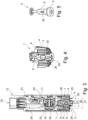
- the 3 shows the shower 12 in a longitudinal section.
- the liquid can be guided within a shower housing 21 of the shower 12 from the inlet 19 via a liquid channel 20 to a valve 10 of the shower 12 .
- the valve 10 includes a valve body 22 which can be adjusted between a first valve seat 23 and a second valve seat 24 by the switching element 11 . If the valve body 22 is located on the first valve seat 23, the liquid channel 20 is connected to the first jet generator 3 of a jet regulator 1 in a liquid-conducting manner, so that the liquid can be released via the first jet generator 3 as a laminar jet.
- a first liquid discharge opening 25 of the first jet former 3 has an annular cross section with an inner diameter 26 and an outer diameter 27 so that the laminar jet has an annular cross section at least immediately after it is discharged through the first jet former 3 .
- the valve body 22 is located on the second valve seat 24, the liquid channel 20 is connected to the second jet former 4 in a liquid-conducting manner, so that the liquid can be discharged via the second jet former 4 as a mist jet.
- the second jet former 4 is formed from a nozzle element 5 and a feed element 6 which are inserted from opposite directions into a cylindrical or tubular receptacle 28 of the first jet former 3 .
- the shower head 12 includes an inlet channel 7 via which the liquid can be guided from the valve 10 into an inlet chamber 9 of the second jet generator 4 .
- the inlet channel 7 opens into the inlet chambers 9 at an angle to a longitudinal axis 8 of the second jet former 4 , so that the liquid can flow through the inlet chambers 9 as an eddy current to a nozzle 29 of the nozzle element 5 .
- the nozzle 29 tapers parallel to the longitudinal axis 8 in the direction of a nozzle tip or second liquid discharge opening 30 of the second jet former 4.
- the second liquid discharge opening 30 has a diameter 31.
- the 4 shows the first variant of the jet regulator 1 in a perspective longitudinal section.
- the first jet former 3 has a multiplicity of flow channels 32 which extend parallel to the longitudinal axis 8 of the second jet former 4 or of the jet regulator 1 .
- the flow channels 32 are arranged so close together that the liquid emerges from the first liquid discharge opening 25 of the first jet former 3 as a laminar jet.
- the figure 5 shows the second jet former 4 with the nozzle element 5 and the feed element 6 in FIGS Figures 3 and 4 shown first embodiment of the jet regulator 1.
- the liquid flows as an eddy current through the in the Figures 3 and 4 Shown inlet chamber 9 along the feed element 6 and occurs via an opening 33 of the feed element 6 as a vortex flow in the Figures 3 and 4 shown nozzle 29 of the nozzle element 5, so that the liquid can be discharged through the second jet generator 4 as a mist jet.
- the 6 shows a second embodiment of the jet regulator 1 in a perspective longitudinal section
- the 8 a third embodiment of the jet regulator 1 in a perspective longitudinal section
- the 10 a fourth embodiment of the jet regulator 1 in a perspective longitudinal section.
- the first jet generator 3 of the second, third and fourth embodiment variant of the jet regulator 1 are identical to that in FIGS Figures 3 and 4 shown first jet generator 3 of the first embodiment of the jet regulator 1 is formed.
- the 7 shows the second beam former 4 in FIG 6 shown second embodiment of the jet regulator 1 in a perspective view
- the 9 the second beam former 4 in the 8 shown third embodiment of the jet regulator 1 in a perspective view
- the 11 the second beam former 4 in the 10 shown fourth Embodiment of the jet regulator 1 in a perspective view.
- the second jet generator 4 of the second, third and fourth embodiment variant of the jet regulator 1 differ from that in FIGS Figures 3 to 5 shown second jet generator 4 of the first embodiment of the jet regulator 1 only slightly.
- the liquid flows as a turbulent flow through the inflow chambers 9 along the feed element 6 and passes through at least one opening 33 of the feed element 6 or the nozzle element 5 as a turbulent flow into the Figures 6, 8 and 10 shown nozzle 29 of the nozzle element 5, so that the liquid can be discharged through the second jet generator 4 as a mist jet.
- the liquid consumption of the liquid can be reduced by the present invention.
Landscapes
- Health & Medical Sciences (AREA)
- Life Sciences & Earth Sciences (AREA)
- Engineering & Computer Science (AREA)
- Hydrology & Water Resources (AREA)
- Public Health (AREA)
- Water Supply & Treatment (AREA)
- Nozzles (AREA)
Applications Claiming Priority (1)
| Application Number | Priority Date | Filing Date | Title |
|---|---|---|---|
| DE102021131207.8A DE102021131207A1 (de) | 2021-11-29 | 2021-11-29 | Strahlregler für eine Sanitärarmatur sowie Sanitärarmatur mit einem solchen Strahlregler |
Publications (1)
| Publication Number | Publication Date |
|---|---|
| EP4190984A1 true EP4190984A1 (fr) | 2023-06-07 |
Family
ID=84358236
Family Applications (1)
| Application Number | Title | Priority Date | Filing Date |
|---|---|---|---|
| EP22207581.4A Pending EP4190984A1 (fr) | 2021-11-29 | 2022-11-15 | Régulateur de jet pour une armature sanitaire et armature sanitaire dotée d'un tel régulateur de jet |
Country Status (3)
| Country | Link |
|---|---|
| US (1) | US20230167632A1 (fr) |
| EP (1) | EP4190984A1 (fr) |
| DE (1) | DE102021131207A1 (fr) |
Families Citing this family (5)
| Publication number | Priority date | Publication date | Assignee | Title |
|---|---|---|---|---|
| CA201931S (en) * | 2020-09-14 | 2022-08-16 | Blanco Gmbh & Co Kg | Tap |
| USD974525S1 (en) * | 2021-02-23 | 2023-01-03 | Neoperl Gmbh | Faucet stream straightener |
| USD1029996S1 (en) * | 2021-08-26 | 2024-06-04 | Blanco Gmbh + Co Kg | Tap |
| USD1018784S1 (en) * | 2022-02-21 | 2024-03-19 | Graff Faucets | Kitchen faucet |
| USD1032788S1 (en) * | 2022-07-07 | 2024-06-25 | Xiamen Lota International Co., Ltd. | Kitchen faucet |
Citations (3)
| Publication number | Priority date | Publication date | Assignee | Title |
|---|---|---|---|---|
| US20190184409A1 (en) * | 2016-11-10 | 2019-06-20 | Xuedong Wang | Shower head structure |
| DE202018103156U1 (de) * | 2018-06-06 | 2019-09-09 | Ikea Supply Ag | Wasserauslassvorrichtung |
| EP3277433B1 (fr) * | 2015-04-02 | 2021-11-17 | Neoperl GmbH | Buse d'atomiseur |
Family Cites Families (2)
| Publication number | Priority date | Publication date | Assignee | Title |
|---|---|---|---|---|
| DE102020106255A1 (de) | 2020-03-09 | 2021-09-09 | Grohe Ag | Brause für eine Sanitärarmatur mit zumindest einem rotierbaren ersten Flüssigkeitsauslass sowie Sanitärarmatur mit einer entsprechenden Brause |
| DE102020124931A1 (de) | 2020-09-24 | 2022-03-24 | Grohe Ag | Sanitärarmatur mit zumindest einem ersten Flüssigkeitsauslass und zumindest einem zweiten Flüssigkeitsauslass |
-
2021
- 2021-11-29 DE DE102021131207.8A patent/DE102021131207A1/de active Pending
-
2022
- 2022-11-15 EP EP22207581.4A patent/EP4190984A1/fr active Pending
- 2022-11-29 US US18/070,838 patent/US20230167632A1/en active Pending
Patent Citations (3)
| Publication number | Priority date | Publication date | Assignee | Title |
|---|---|---|---|---|
| EP3277433B1 (fr) * | 2015-04-02 | 2021-11-17 | Neoperl GmbH | Buse d'atomiseur |
| US20190184409A1 (en) * | 2016-11-10 | 2019-06-20 | Xuedong Wang | Shower head structure |
| DE202018103156U1 (de) * | 2018-06-06 | 2019-09-09 | Ikea Supply Ag | Wasserauslassvorrichtung |
Also Published As
| Publication number | Publication date |
|---|---|
| US20230167632A1 (en) | 2023-06-01 |
| DE102021131207A1 (de) | 2023-06-01 |
Similar Documents
| Publication | Publication Date | Title |
|---|---|---|
| EP4190984A1 (fr) | Régulateur de jet pour une armature sanitaire et armature sanitaire dotée d'un tel régulateur de jet | |
| EP2969234B1 (fr) | Buse de pulvérisation pour sortie d'eau sanitaire et robinet sanitaire pourvu d'une sortie d'eau | |
| DE69002176T2 (de) | Zerstäubungsdüse für eine Zerstäubungspistole zur Erzeugung einer Polyurethanschicht auf einer Fläche. | |
| DE112012005017B4 (de) | Vorrichtung zum Steuern einer Fluid-Strömung in einem Notfall-Waschsystem, Vorrichtung zum Steuern einer Fluid-Strömung und Waschsystem zum Liefern einer Fluid-Strömung | |
| EP1852190B1 (fr) | Générateur de mousse | |
| DE69005267T2 (de) | Brauseeinheit. | |
| DE102020106255A1 (de) | Brause für eine Sanitärarmatur mit zumindest einem rotierbaren ersten Flüssigkeitsauslass sowie Sanitärarmatur mit einer entsprechenden Brause | |
| EP4036329B1 (fr) | Régulateur de jet pour une armature sanitaire, ainsi qu'armature sanitaire dotée d'un tel régulateur de jet | |
| DE8526472U1 (de) | Einströmdüse, insbesondere für Schwimmbäder | |
| EP3935229B1 (fr) | Régulateur de jet | |
| EP1359260A2 (fr) | Pomme de douche | |
| DE102020124931A1 (de) | Sanitärarmatur mit zumindest einem ersten Flüssigkeitsauslass und zumindest einem zweiten Flüssigkeitsauslass | |
| EP3546421B1 (fr) | Dispositif de distribution comportant un insert de buse doté d'une paroi d'impact | |
| DE102011079982A1 (de) | Sprühkopf für reaktive Kunststoffe | |
| EP0996585A1 (fr) | Dispositif pour melanger au moins deux milieux en ecoulement | |
| EP4111007A1 (fr) | Régulateur de jet pour appareil sanitaire comprenant au moins trois canaux de fluide | |
| DE102011102693B4 (de) | Löschdüsenkopf mit Strömungskanal | |
| WO2020182491A1 (fr) | Douche sanitaire présentant un dispositif de formation de jets pourvu d'au moins une valve en bec de canard | |
| EP3310971B1 (fr) | Appareil de robinetterie sanitaire pour plusieurs fluides | |
| EP0264689B1 (fr) | Appareil producteur de mousse | |
| CH201450A (de) | Luftschaumerzeuger. | |
| DE102013002235A1 (de) | Luftansaugvorrichtung für eine Sanitärbrause | |
| DE202007006542U1 (de) | Schaumeinrichtung | |
| DE202005001165U1 (de) | Sanitäre Auslaufeinheit | |
| DE102021106446A1 (de) | Umstellventil für eine Sanitärarmatur sowie Sanitärarmatur mit einem solchen Umstellventil |
Legal Events
| Date | Code | Title | Description |
|---|---|---|---|
| PUAI | Public reference made under article 153(3) epc to a published international application that has entered the european phase |
Free format text: ORIGINAL CODE: 0009012 |
|
| STAA | Information on the status of an ep patent application or granted ep patent |
Free format text: STATUS: THE APPLICATION HAS BEEN PUBLISHED |
|
| AK | Designated contracting states |
Kind code of ref document: A1 Designated state(s): AL AT BE BG CH CY CZ DE DK EE ES FI FR GB GR HR HU IE IS IT LI LT LU LV MC ME MK MT NL NO PL PT RO RS SE SI SK SM TR |
|
| STAA | Information on the status of an ep patent application or granted ep patent |
Free format text: STATUS: REQUEST FOR EXAMINATION WAS MADE |
|
| 17P | Request for examination filed |
Effective date: 20231206 |
|
| RBV | Designated contracting states (corrected) |
Designated state(s): AL AT BE BG CH CY CZ DE DK EE ES FI FR GB GR HR HU IE IS IT LI LT LU LV MC ME MK MT NL NO PL PT RO RS SE SI SK SM TR |