EP4110552B1 - Outil de polissage - Google Patents
Outil de polissage Download PDFInfo
- Publication number
- EP4110552B1 EP4110552B1 EP21709892.0A EP21709892A EP4110552B1 EP 4110552 B1 EP4110552 B1 EP 4110552B1 EP 21709892 A EP21709892 A EP 21709892A EP 4110552 B1 EP4110552 B1 EP 4110552B1
- Authority
- EP
- European Patent Office
- Prior art keywords
- polishing
- lamellae
- tool
- polishing tool
- grinding
- Prior art date
- Legal status (The legal status is an assumption and is not a legal conclusion. Google has not performed a legal analysis and makes no representation as to the accuracy of the status listed.)
- Active
Links
Images


Classifications
-
- B—PERFORMING OPERATIONS; TRANSPORTING
- B24—GRINDING; POLISHING
- B24D—TOOLS FOR GRINDING, BUFFING OR SHARPENING
- B24D13/00—Wheels having flexibly-acting working parts, e.g. buffing wheels; Mountings therefor
- B24D13/14—Wheels having flexibly-acting working parts, e.g. buffing wheels; Mountings therefor acting by the front face
- B24D13/16—Wheels having flexibly-acting working parts, e.g. buffing wheels; Mountings therefor acting by the front face comprising pleated flaps or strips
-
- B—PERFORMING OPERATIONS; TRANSPORTING
- B24—GRINDING; POLISHING
- B24D—TOOLS FOR GRINDING, BUFFING OR SHARPENING
- B24D13/00—Wheels having flexibly-acting working parts, e.g. buffing wheels; Mountings therefor
- B24D13/02—Wheels having flexibly-acting working parts, e.g. buffing wheels; Mountings therefor acting by their periphery
- B24D13/04—Wheels having flexibly-acting working parts, e.g. buffing wheels; Mountings therefor acting by their periphery comprising a plurality of flaps or strips arranged around the axis
Definitions
- the invention relates to a polishing tool, in particular for rotational drive by a machine tool, in particular a hand-held machine, about a rotation axis, with a carrier body and a polishing body attached to the carrier body, wherein the polishing body comprises a number of lamellae.
- Polishing involves the fine processing of surfaces using a polishing tool that is moved relative to the workpiece.
- the energy input via the relative movement and the contact pressure means that the surface of a workpiece, particularly a metal one, is processed without any significant change in the workpiece contour by leveling the surface roughness, removing any contamination and, to a lesser extent, removing material from roughness peaks on the workpiece surface.
- a polishing agent is usually used that consists of unbound mineral powder, usually metal oxides with a high melting point and a low tendency to dissolve in water or oil.
- the mineral powder forms particles with a geometrically undetermined shape.
- the mineral powder is slurried or processed into polishing pastes or polishing agent suspensions by mixing it with heat-resistant fats or paraffins. The particles transfer the pressure of the tool from the particles to the workpiece surface at specific points via the very small contact area, leading to local and short-term flow processes that reduce the surface roughness.
- hand-held machines with polishing tools are usually used that do not have a workpiece-specific contour and are not intended for shaping the workpiece. Rather, polishing is usually used to rework the surface for decorative purposes or to restore such a surface in a repair shop (e.g. polishing painted parts, polishing out scratches), or for technical reasons, e.g. in mold making.
- hand-held machines that come into consideration here are hand drills, angle grinders or straight grinders.
- buffing discs or buffing bells are known for use on vehicle bodies before and after painting, in which the polishing body of the polishing tool consists of a package of cotton cloths placed on top of each other and quilted together according to the desired strength. which are arranged radially to a bore of a clamping pin or to such a clamping pin.
- the main advantage of such buffing wheels is the even lower transfer of the tool contour to the workpiece, so that even with highly sensitive surfaces, e.g. piano lacquer, the formation of marks can be largely ruled out.
- the disadvantage is the relatively low performance.
- solid felt polishing discs are known as felt polishing bodies, which can be used with mandrels to attach the felt polishing discs to machines.
- a number of contoured felt polishing bodies are also known, ranging from small spherical shapes of felt to various partially conical designs to cylindrical solid felt polishing bodies.
- These felt polishing bodies are also provided with shafts for mounting in standard drill chucks.
- polishing wheel made of a fiber material and the use of such a polishing wheel for polishing watch cases is known.
- a relatively narrow polishing wheel is described, for which it is stated as a special feature that it consists of a single solid fiber material, with the wheel being cut transversely from the outer circumference towards the center.
- Three radial zones are formed in the wheel. The outer zone has a large number of such cuts. Only every second of the cuts continues into the radially inner zone. The radially innermost zone has no such cuts.
- these cuts do not run exactly radially, but are curved against the direction of rotation and the tangents of the curved cut are offset by a Angle ⁇ are inclined, with the angle ⁇ increasing from the outside to the inside.
- an inclination of 20° is given as the preferred value for the angle ⁇ .
- the inclination is such that the tangents point past the core of the disk in the direction of rotation, i.e. the slotted radially outer parts of the polishing disk are pressed together by the inertia during rotation and thus make the polishing disk particularly hard in the radial direction.
- the slotting is intended to enable improved lateral (axial) mobility of the disk.
- polishing disk that is very hard in the radial direction, but relatively flexible in the axial direction.
- the workpiece is machined using the radially outer circumference of the tool.
- abrasives in the form of abrasive grains are used that are bonded to the tool.
- the tool contour is transferred to the workpiece to a greater or lesser extent when the workpiece surface is machined.
- bonded abrasives In grinding tools with bonded grain, also known as bonded abrasives, the abrasive grains are embedded in a synthetic resin mass. These grinding tools are used in the form of grinding stones and grinding wheels for shaping and surface finishing of workpieces. Such grinding tools are rigid, which on the one hand makes it easier to create a surface contour, but brings with it the problem that abrasive grains can break off uncontrollably and in larger fractions, thus leading to an uneven grinding pattern on the surface of the workpiece.
- abrasives on a backing In contrast to this, there are abrasives on a backing. These are described in detail in DIN ISO 16057. Paper, fabric, polyester and fiber (vulcanized fiber) can be used as the carrier material for abrasives on a backing. These carrier materials enable the production of grinding tools with a uniform coating of abrasive grains of various grain sizes and abrasives. The abrasive grains are fixed to the carrier material with a synthetic resin bond. Since the carrier material of the abrasives on a backing is flexible, such abrasives are also referred to as flexible abrasives.
- a supporting support part is required for use when grinding with machines, usually in the form of a so-called backing plate, as standardized in DIN ISO 15636.
- backing plate usually in the form of a so-called backing plate
- sections of carrier fabric with abrasive material in a plastic bond in the form of lamellas.
- Such a tool also known in practice as a fan grinder, is used, for example, in the DE 79 03 893 U1 described.
- a disc grinding tool is proposed with grinding lamellae arranged radially with respect to the grinding tool axis, perpendicular to the tool body.
- two intermediate elements are arranged between the grinding lamellae.
- the first intermediate element should consist of a pressure-elastic material and should come into contact with the side of the lamella that is not coated with abrasive.
- a further intermediate element is arranged between this intermediate element and the side of the lamella that is coated with abrasive.
- This intermediate element is preferably made of a plastic and has good bending properties, but has a higher wear resistance than the first intermediate element. This arrangement is intended to improve the wear behavior of the intermediate elements during operation of the grinding tool.
- a flap grinding tool known with a sequence of overlapping flaps, the abrasive grains , these lamellae being formed alternately from abrasive lamellae and compressible lamellae.
- Each abrasive lamellae should rest with its operative part on a compressible lamellae and be supported by the compressible lamellae.
- the lamellae should also be able to be combined to form groups of lamellae of the type in question.
- WO 2015/085211 A1 describes a coated abrasive material with a backing comprising a web or fleece made of a polyester-based material, impregnated with a phenolic resin, an acrylic resin, a urethane resin or a combination thereof, with an abrasive layer covering the backing containing abrasive particles.
- a lamellar grinding tool is known in which grinding lamellas are bundled into packages and intermediate layers of abrasive fleece are arranged between adjacent grinding lamella packages.
- Lamellar grinding tools with consecutive lamellas made of abrasive fleece and abrasive cloth are available from SKDS sro, Lu ⁇ any u P ⁇ e ⁇ tic, CZ, on the SKDS.cz website under the name "Lamelové kombinované kotou ⁇ e s up ⁇ nac ⁇ stopkou", type designation BKC, in the various abrasive combinations corundum/corundum, corundum/zirconium, carbide/corundum.
- a flap disc is known with first lamellae made of a base, a base bonding layer applied to the base, a scattering layer of abrasive grain applied to the base bonding layer and a cover layer applied to the scattering layer of abrasive grain, and second lamellae consisting of a base and a layer of grinding-active substances applied to the base. Potassium fluoroborate, cryolite, calcium fluoride and chiolite are proposed as grinding-active substances. This type of design should make it possible to produce a flap disc with reduced manufacturing and material costs.
- a flap grinding wheel is known in which the flaps are arranged in a shingle-like overlapping manner on the grinding plate.
- the flaps are made of cotton or polyester fabric, to which abrasive particles are bound using phenolic resin.
- the proposed arrangement is intended to result in worn abrasive particles breaking off at the wear edges of the flaps and the then exposed, relatively flexible carrier fabric quickly wearing away, thus exposing fresh abrasive grains, with which the grinding process can be continued continuously. This is intended to prevent grinding marks caused by setting the tool down and New preparation after replacing a worn or clogged grinding wheel can be reduced.
- the carrier fabric be replaced with a fleece material onto which the mixture of resin and grinding particles is applied.
- grinding particles be embedded in the resin matrix of a grinding disc made of glass fiber reinforced plastic.
- a polishing brush which consists of strips of a nonwoven material, wherein the number of strips increases from the center of the carrier disk to the radially outer edge, so that the density of the strips is uniform or can also be set higher at the radially outer edge.
- a porous polishing tool and a method for polishing a roller are known, which are said to make it possible to polish a roller within a satisfactory dimensional accuracy while avoiding feed marks and striped printing effects when the polished roller is to be used for printing.
- a polishing disc which has a short fiber pile layer with a strong bond to a holding layer, and in which a Velcro layer is attached to the back of the polishing disc in order to removably attach the polishing disc to a corresponding polishing plate.
- the advantage stated is that it is possible to remove the polishing disc from the polishing plate and wash it in household or industrial washing machines, thereby removing dried polishing agent and polishing dust. This is intended to ensure that the polishing disc can be used several times.
- a lamellar polishing tool is known in which the polishing body is divided into multiple parts, thereby forming a number of lamellae.
- lamellae made of polishing felt of different densities. It is also disclosed there to provide one or more intermediate layers between at least some of the felt lamellae to stiffen the tool.
- a disk as a carrier body and to arrange the felt lamellae radially projecting on the axial face of the disk. With such an embodiment, inner edge areas can also be polished particularly well.
- polishing paste For use with the known polishing tools described above, it is necessary to select a suitable polishing paste that matches the hardness of the felt material and its porosity.
- the type of grease or oil used is particularly important in order to avoid premature clogging of the polishing tool. Such premature clogging leads to streaks and smears on the workpiece and, in extreme cases, can lead to burn marks.
- polishing wheels described in the utility model DE-GM 1 940 005 in which an adapted polishing agent is to be integrated in a soft bond.
- the textile is to be soaked in the polishing agent preparation or such a preparation is to be embedded, for example, by wrapping it in pieces of cloth. It is emphasized that the cloth-like character of such a polishing wheel is to be retained, as is the case with the known polishing wheels made up of flat or puffed-up cloth layers.
- the operator must maintain an appropriate contact pressure in order to achieve the desired polishing effect and to avoid overheating.
- overheating can lead to burn marks on the workpiece or to carbonization of the polishing felt, which in turn can lead to scratches on the workpiece when the polishing tool is used in the future.
- the polishing result therefore depends on a certain amount of experience and practice on the part of the operator as well as his experience in selecting a suitable polishing body with the appropriate hardness and a polishing agent adapted to the material of the workpiece and the polishing body.
- the invention is therefore based on the object of providing a polishing tool which has improved properties with regard to its handling and with regard to more efficient use of work.
- a polishing tool of the type mentioned at the outset for rotational drive by a drive machine about a rotation axis with a carrier body, and a polishing body attached to the carrier body, wherein the polishing body comprises a number of first lamellae and at least a number of second lamellae, wherein the first lamellae comprise a polishing felt and the second lamellae comprise a fleece, wherein the fleece is formed essentially from plastic fibers and wherein the fleece has a greater porosity than the polishing felt.
- the porosity of the fleece is formed by the hollow spaces between the fibers. This means that the fleece absorbs the polishing paste that needs to be added during operation and gradually releases it as the tool is used. The fleece therefore acts as a depot for the polishing paste during operation.
- the polishing agent can be better distributed over the surface of the polishing tool and the risk of the felt becoming clogged and thus smearing spots on the workpiece on the one hand or the polishing tool running dry on the workpiece on the other hand can be better avoided.
- a polishing tool according to the invention now makes it possible to finely grind and polish an unprocessed workpiece surface in a single operation with just one tool. Due to the depot effect of the abrasive fleece for the polishing agent, in many cases it is no longer necessary to interrupt the polishing process to add more polishing agent, which not only saves a considerable amount of time, but also avoids damage to the surface due to interruptions that require rework.
- a polishing tool according to the invention therefore enables faster and more effective fine processing of a workpiece surface for the majority of typical applications. The fine processing of workpiece surfaces can therefore be carried out much more economically with the polishing tool according to the invention than with the tools known to date.
- the carrier body is designed as a carrier disk.
- the carrier disk can preferably be made as a resin-bonded glass fiber disk or essentially from a plastic, preferably a fiber-reinforced plastic, from aluminum, a hard paper (fiber material), a composite material or from steel.
- the lamellae are preferably arranged along the circumference of the carrier disk, preferably projecting radially beyond it, on the axial front side of the disk.
- inner edge areas can also be polished particularly well.
- first and second lamellae are aligned essentially parallel to the axis of rotation.
- Such a polishing tool according to the invention can also be applied over the entire surface for polishing, corresponding to an angle of attack of 0°.
- first and second lamellae are arranged at an angle to the axis of rotation and the carrier disk, preferably projecting radially beyond the edge of the carrier disk.
- the second lamellae For good removal performance, e.g. when burrs are to be removed during fine machining, it is advisable for the second lamellae to comprise a fleece with abrasives bound to fibres.
- a grain size of at least 320 is preferable, corresponding to a particle size of less than 50 ⁇ m.
- the second lamellae comprise a fleece without fibre-bound abrasives.
- the material of the plastic fibers consists of a plastic filled with an aluminum silicate powder.
- the polishing body further comprises a number of third lamellae, the second and third lamellae each comprising a fleece with and without abrasives bound to fibers.
- the advantages of fleece lamellae with and without abrasives can be combined, while at the same time a particularly flexible polishing tool for strongly contoured surfaces can be obtained.
- the polishing body has first and second lamellae in a ratio of 1:1, 1:2 or 1:3.
- the second fleece lamellae are at least partially filled with a polishing paste.
- the polishing paste is located in the cavities between the fibers of the fleece. This creates a polishing agent reservoir from which polishing agent is continuously released during the processing process.
- the amount of polishing agent can be adjusted via the thickness and density of the fleece so that the polishing agent reservoir in the fleece lamellae is sufficient for the service life of the tool.
- the user of the tool is therefore not concerned with questions of selecting the right polishing agent and adding appropriate amounts of polishing agent.
- Such a tool is particularly suitable for the repeated processing of larger areas, even by semi-skilled personnel.
- the polishing body of the polishing tool is provided with a covering until it is used, which prevents the polishing agent from drying out.
- the covering can be in the form of a film or in the form of a wax covering, for example. The covering is usually removed by the user before the tool is used.
- the covering can also be formed by a - possibly reusable - packaging for one or more of the polishing tools according to the invention.
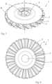
- the polishing tool according to the invention shown in the figures, designated overall by 1, is designed for rotational drive by a machine tool about a rotation axis 2.
- the polishing tool 1 has a polishing body which a number of first lamellae 3 and at least a number of second lamellae 4.
- the first and second lamellae 3, 4 are attached to a carrier disk 5 as a carrier body.
- the carrier disk 5 has a receiving surface which is rotationally symmetrical to the rotation axis 2 of the polishing tool 1 and to which the lamellae 3, 4 are attached, for example by means of a synthetic resin adhesive.
- the receiving surface is arranged axially on the front side of the carrier disk 5.
- the first lamellae 3 are made of a polishing felt.
- the felt material of the first lamellae 3 can comprise conventional polishing felts, for example and preferably polishing felt with a pure wool (animal hair) content of at least about 30% and preferably a hardness of 0.14 to 0.68 (W4 to H5) according to DIN 61200. In particular, significantly less polishing residue is left on the workpiece than with other polishing materials.
- the second lamellae 4 comprise a fleece, whereby the fleece is essentially made of plastic fibers.
- the fleece has a greater porosity than the polishing felt.
- Abrasive fleeces consist of plastic fibers, usually nylon, polyester or mixtures thereof. Depending on the processing, abrasive fleeces of different elasticity and strength are produced.
- a method for producing an abrasive fleece with abrasive material in the form of abrasive grains bonded to the fibers is known, for example, from WO 2017/072293 A1 and the US 2018/0326556 A1
- the porosity of the fleece is formed by the relatively large cavities between the fibers.
- the fleece absorbs the polishing paste that needs to be added during operation and gradually releases it as the tool is used.
- the fleece therefore acts as a depot for the polishing paste during operation.
- a polishing tool according to the invention makes it possible to finely grind and polish an untreated workpiece surface in a single operation using only one tool. Due to the depot effect of the abrasive fleece for the polishing agent, in many cases it is no longer necessary to interrupt the polishing process to add more polishing agent, which not only results in considerable time savings, but also prevents any impairment of the Surface can be avoided due to interruptions that require rework.
- a polishing tool according to the invention therefore enables faster and more effective fine machining of a workpiece surface for the majority of typical applications. The fine machining of workpiece surfaces can therefore be carried out much more economically with the polishing tool according to the invention than with previously known tools.
- the carrier disk 5 can be made as a resin-bonded glass fiber plate or from a plastic, preferably a fiber-reinforced plastic, from aluminum, a hard paper (fiber material) or from steel.
- the carrier disk 5 is expediently designed to be cranked as shown in the figures. This allows the working distance between the drive machine and the workpiece surface to be increased for strongly contoured workpieces, and on the other hand such a stiffer design of the carrier disk 5 counteracts fluttering of the polishing tool 1.
- the Figures 3, 4 , 7, 8 , 11 and 12 The embodiments of a polishing tool 1 according to the invention shown have a carrier disk 5 with a hole 6 for receiving a conventional mandrel for connection to a drive machine.
- the carrier disk 5 is manufactured from a fiber-reinforced plastic
- the edge of the hole 6 is expediently reinforced with a metal eyelet 7 in order to guarantee a secure, central fit.
- a diameter of the hole 6 of 22.23 mm is suitable for many angle grinders.
- a driver element 8 is to be provided in the area of the carrier disk 5 and a single or multiple screw or nut thread is to be arranged in the driver element 8.
- a connecting nut thread of size M14 or 5/8-11" would be particularly suitable here.
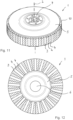
- first and second lamellae 3, 4 are aligned essentially parallel to the rotation axis 2, i.e. standing on the axial front side of the carrier disk 5.
- the lamellae 3, 4 are arranged along the circumference of the carrier disk 5, preferably projecting radially beyond it. This is particularly good in the Figures 1 to 4 and 9 to 12
- Such a polishing tool according to the invention can also be applied over the entire surface for polishing, corresponding to an angle of attack of 0°.
- first and second lamellae 3, 4 are arranged at an angle to the rotation axis 2 and the carrier disk 5, also preferably projecting radially beyond the edge of the carrier disk 5.
- Such an arrangement is also often referred to as "lying”.
- Embodiments with such an arrangement of the lamellae 3, 4 are shown in the Figures 5 to 8 shown.
- the Figures 1 , 3 , 5 , 7 , 9 and 11 show a perspective view of the embodiments of a polishing tool 1 according to the invention seen from the drive machine side.
- the Figures 2 , 4 , 6 , 8th , 10 and 12 show a plan view of the embodiments of a polishing tool 1 according to the invention seen from the workpiece side.
- a thickness of the lamellae 3, 4 of approximately 1 mm to approximately 20 mm, preferably in the range of approximately 3 mm to approximately 10 mm.
- the thickness of the first lamellae 3 and the second lamellae 4 can be adapted.
- Narrower first lamellae 3 in combination with thicker second lamellae 4 result in greater aggressiveness, i.e. higher removal performance.
- the second lamellae 4 comprise a fleece with abrasives bound to fibers.
- a grain size of at least about P320 according to FEPA or finer is preferable, corresponding to a particle size of less than about 50 ⁇ m.
- the second lamellae 4 comprise a fleece without any fibre-bound abrasives.
- the material of the plastic fibres consists of a plastic filled with an aluminium silicate powder.
- the polishing body further comprises a number of third lamellae 9, the second and third lamellae 4, 9 each comprising a fleece with and without abrasives bound to fibers.
- the advantages of fleece lamellae with and without abrasives can be combined, and at the same time a particularly flexible polishing tool 1 for strongly contoured surfaces can be obtained.
- Such an embodiment is shown in the Figures 9 and 10 to see.
- the polishing body has first and second lamellae 3, 4 in a ratio of 1:1, 1:2 or 1:3.
- An embodiment of a polishing tool 1 according to the invention with first and second lamellae 3, 4 in a ratio of 1:2 is shown in the Figures 11 and 12 shown.
- the second lamellae 4 made of fleece are at least partially filled with a polishing paste.
- the polishing paste is located in the cavities between the fibers of the fleece.
- the amount of polishing agent can be adjusted via the thickness and density of the fleece so that the polishing agent depot in the fleece lamellae is sufficient for the service life of the tool.
- the user of the polishing agent depot according to the invention The polishing tool 1 is therefore not concerned with questions of selecting the right polishing agent and adding appropriate amounts of polishing agent.
- Such a polishing tool 1 according to the invention is particularly suitable for the repeated processing of larger surfaces, even by semi-skilled personnel.
- the polishing body of the polishing tool 1 is provided with a covering until it is used, which prevents the polishing agent from drying out.
- the covering can be designed, for example, in the form of a film or in the manner of a wax covering. The covering is usually removed by the user before using the tool 1.
- the covering can also be formed by a - possibly reusable - packaging for one or more of the polishing tools 1 according to the invention.
Landscapes
- Engineering & Computer Science (AREA)
- Mechanical Engineering (AREA)
- Polishing Bodies And Polishing Tools (AREA)
Claims (10)
- Outil de polissage (1) pour l'entraînement rotatif par une machine d'entraînement autour d'un axe de rotation (2), avec un corps de support, ainsi qu'un corps de polissage monté au niveau du corps de support, dans lequel le corps de polissage comprend un nombre de premières lamelles (3) et au moins un nombre de deuxièmes lamelles (4), dans lequel les premières lamelles (3) comprennent un feutre de polissage et les deuxièmes lamelles (4) comprennent un non-tissé, dans lequel le non-tissé est formé sensiblement en fibres plastiques et dans lequel le non-tissé présente une porosité supérieure à celle du feutre de polissage.
- Outil de polissage (1) selon la revendication 1, caractérisé en ce que le corps de support est réalisé comme disque de support (5).
- Outil de polissage (1) selon l'une quelconque des revendications précédentes, caractérisé en ce que les premières et deuxièmes lamelles (3, 4) sont orientées sensiblement parallèlement à l'axe de rotation (2).
- Outil de polissage (1) selon l'une quelconque des revendications 1 ou 2, caractérisé en ce que les premières et deuxièmes lamelles (3, 4) sont agencées inclinées dans un angle par rapport à l'axe de rotation (2) et au disque de support (5).
- Outil de polissage (1) selon l'une quelconque des revendications précédentes, caractérisé en ce que les deuxièmes lamelles (4) comprennent un non-tissé avec un abrasif lié aux fibres.
- Outil de polissage (1) selon l'une quelconque des revendications 1 à 4, caractérisé en ce que les deuxièmes lamelles (4) comprennent un non-tissé sans abrasif lié aux fibres.
- Outil de polissage (1) selon l'une quelconque des revendications précédentes, caractérisé en ce que le corps de polissage comprend de plus un nombre de troisièmes lamelles (9), dans lequel les deuxièmes et troisièmes lamelles (4, 9) comprennent respectivement un non-tissé avec et sans abrasif lié aux fibres.
- Outil de polissage (1) selon l'une quelconque des revendications 5 et 7, caractérisé en ce que l'abrasif lié aux fibres présente une grosseur de grains d'au moins 320.
- Outil de polissage (1) selon l'une quelconque des revendications précédentes, caractérisé en ce que le corps de polissage présente des premières et deuxièmes lamelles (3, 4) dans un rapport de 1:1, 1:2 ou 1:3.
- Outil de polissage (1) selon l'une quelconque des revendications précédentes, caractérisé en ce qu'au moins les deuxièmes lamelles (4) en non-tissé sont remplies au moins partiellement avec une pâte de polissage.
Applications Claiming Priority (3)
| Application Number | Priority Date | Filing Date | Title |
|---|---|---|---|
| DE102020001283.3A DE102020001283A1 (de) | 2020-02-28 | 2020-02-28 | Polierwerkzeug |
| DE202020000786.2U DE202020000786U1 (de) | 2020-02-28 | 2020-02-28 | Polierwerkzeug |
| PCT/EP2021/025080 WO2021170298A1 (fr) | 2020-02-28 | 2021-02-28 | Outil de polissage |
Publications (2)
| Publication Number | Publication Date |
|---|---|
| EP4110552A1 EP4110552A1 (fr) | 2023-01-04 |
| EP4110552B1 true EP4110552B1 (fr) | 2024-04-10 |
Family
ID=74858385
Family Applications (1)
| Application Number | Title | Priority Date | Filing Date |
|---|---|---|---|
| EP21709892.0A Active EP4110552B1 (fr) | 2020-02-28 | 2021-02-28 | Outil de polissage |
Country Status (4)
| Country | Link |
|---|---|
| US (1) | US20230136260A1 (fr) |
| EP (1) | EP4110552B1 (fr) |
| MX (1) | MX2022010370A (fr) |
| WO (1) | WO2021170298A1 (fr) |
Families Citing this family (1)
| Publication number | Priority date | Publication date | Assignee | Title |
|---|---|---|---|---|
| DE202024100939U1 (de) * | 2024-02-28 | 2025-05-30 | H. Günther Falkenrich GmbH | Oberflächenbearbeitungswerkzeug sowie damit ausgerüstete Oberflächenbearbeitungsmaschine |
Family Cites Families (17)
| Publication number | Priority date | Publication date | Assignee | Title |
|---|---|---|---|---|
| US3191208A (en) | 1962-04-19 | 1965-06-29 | George R Churchill Company Inc | Buffing wheel |
| US3529385A (en) | 1968-11-12 | 1970-09-22 | Norton Co | Abrasive brush |
| DE7903893U1 (de) | 1979-02-13 | 1979-05-17 | Fa. August Rueggeberg, 5277 Marienheide | Rotations-schleifwerkzeug |
| US4275529A (en) | 1979-08-28 | 1981-06-30 | Minnesota Mining And Manufacturing Company | High flap density abrasive flap wheel |
| DE3145151C2 (de) | 1981-11-13 | 1986-02-06 | Bayerische Motoren Werke AG, 8000 München | Antreibbare Walze zum Überschleifen oder Polieren der Oberfläche einer Fahrzeugkarosserie oder dergleichen |
| CH666377GA3 (fr) | 1986-06-03 | 1988-07-29 | ||
| US5752876A (en) | 1995-10-23 | 1998-05-19 | Weiler Brush Company, Inc. | Flap disc abrasive tool |
| US5833724A (en) * | 1997-01-07 | 1998-11-10 | Norton Company | Structured abrasives with adhered functional powders |
| DE59706987D1 (de) | 1997-12-12 | 2002-05-16 | Botech Ag Ges Fuer Beratung Un | Werkzeug für die schleifende Bearbeitung von Oberflächen |
| JP3006591B2 (ja) | 1998-07-02 | 2000-02-07 | 信濃電気製錬株式会社 | ロール研磨用多孔質砥石及びロール表面の研磨方法 |
| DE19843267A1 (de) | 1998-09-21 | 2000-03-23 | Martin Wiemann | Polierscheibe |
| DE19853550C1 (de) | 1998-11-20 | 2000-03-09 | Ver Schmirgel & Maschf | Fächerschleifscheibe |
| EP1093885A1 (fr) | 1999-10-18 | 2001-04-25 | Botech AG | Outil de meulage |
| DE10042109C2 (de) * | 2000-08-28 | 2003-07-03 | M & F Entw & Patentverwertungs | Polierwerkzeug |
| BE1015278B3 (nl) * | 2004-03-03 | 2005-11-08 | Cibo N V | Schuurelement. |
| WO2015085211A1 (fr) | 2013-12-06 | 2015-06-11 | Saint-Gobain Abrasives, Inc. | Article abrasif revêtu comprenant un matériau non tissé |
| EP3162502A1 (fr) | 2015-10-28 | 2017-05-03 | VSM. Vereinigte Schmirgel- Und Maschinen-Fabriken AG | Non-tisse abrasif et son procede de fabrication |
-
2021
- 2021-02-28 US US17/905,115 patent/US20230136260A1/en not_active Abandoned
- 2021-02-28 EP EP21709892.0A patent/EP4110552B1/fr active Active
- 2021-02-28 WO PCT/EP2021/025080 patent/WO2021170298A1/fr not_active Ceased
- 2021-02-28 MX MX2022010370A patent/MX2022010370A/es unknown
Also Published As
| Publication number | Publication date |
|---|---|
| EP4110552A1 (fr) | 2023-01-04 |
| US20230136260A1 (en) | 2023-05-04 |
| MX2022010370A (es) | 2022-11-08 |
| WO2021170298A1 (fr) | 2021-09-02 |
Similar Documents
| Publication | Publication Date | Title |
|---|---|---|
| DE69831089T2 (de) | Verfahren und vorrichtung zum reinigen und endbearbeiten | |
| EP3999282B1 (fr) | Segment abrasif pour un rouleau de ponçage, ponceuse et utilisation | |
| DE1694594A1 (de) | Schleif- und Polierkoerper | |
| CH646628A5 (de) | Schleifkoerper fuer die metallbearbeitung. | |
| DE102011108859B4 (de) | Rotationssymmetrisches Werkzeug zur spanenden Bearbeitung von Materialoberflächen, Scheibe oder Ringscheibe zur Verwendung bei einem derartigen Werkzeug sowie Verfahren zur Herstellung eines solchen Werkzeugs | |
| DE602005001842T2 (de) | Schleifelement | |
| EP1120198B1 (fr) | Outil de meulage, dispositif ainsi équipé et procédé d'usinage de pièces mettant en oeuvre cet outil | |
| DE10042109C2 (de) | Polierwerkzeug | |
| DE202012101515U1 (de) | Schleifmittel und Schleifwerkzeug | |
| EP1859903B1 (fr) | Outil rotatif pour le traitement de surface | |
| EP2170559B1 (fr) | Outil de polissage de profils de dents et son utilisation | |
| EP4110552B1 (fr) | Outil de polissage | |
| DE2931695C2 (de) | Schleifkörper zum Vor- und Nachschleifen | |
| EP1827762B1 (fr) | Produit abrasif et son procede de production | |
| DE102005003496A1 (de) | Variabler Schneidkantenabzug für Bohrwerkzeuge | |
| DE2322602A1 (de) | Laepp-kissen | |
| DE69911546T2 (de) | Verfahren zum elektrolytischen Polieren von Werkstücken mit Anwendung spezieller Schleifmaterialien | |
| DE202020000786U1 (de) | Polierwerkzeug | |
| DE102020001283A1 (de) | Polierwerkzeug | |
| DE102005056368B4 (de) | Schleifmittel und Verfahren zu dessen Herstellung | |
| DE102025142083A1 (de) | Schleifscheibe und Schleifvorrichtung | |
| DE1239091C2 (de) | Schleifkoerper aus einer ungewebten Bahn aus synthetischen organischen Fasern | |
| EP3755500B1 (fr) | Corps de support pour un outil de ponçage et procédé servant à fabriquer un corps de support | |
| DE102023104054A1 (de) | Polierwerkzeug | |
| DE2125942A1 (de) | Schleifmittel und Verfahren zum Herstellen eines Schleifmittels |
Legal Events
| Date | Code | Title | Description |
|---|---|---|---|
| STAA | Information on the status of an ep patent application or granted ep patent |
Free format text: STATUS: UNKNOWN |
|
| STAA | Information on the status of an ep patent application or granted ep patent |
Free format text: STATUS: THE INTERNATIONAL PUBLICATION HAS BEEN MADE |
|
| PUAI | Public reference made under article 153(3) epc to a published international application that has entered the european phase |
Free format text: ORIGINAL CODE: 0009012 |
|
| STAA | Information on the status of an ep patent application or granted ep patent |
Free format text: STATUS: REQUEST FOR EXAMINATION WAS MADE |
|
| 17P | Request for examination filed |
Effective date: 20220927 |
|
| AK | Designated contracting states |
Kind code of ref document: A1 Designated state(s): AL AT BE BG CH CY CZ DE DK EE ES FI FR GB GR HR HU IE IS IT LI LT LU LV MC MK MT NL NO PL PT RO RS SE SI SK SM TR |
|
| GRAP | Despatch of communication of intention to grant a patent |
Free format text: ORIGINAL CODE: EPIDOSNIGR1 |
|
| STAA | Information on the status of an ep patent application or granted ep patent |
Free format text: STATUS: GRANT OF PATENT IS INTENDED |
|
| DAV | Request for validation of the european patent (deleted) | ||
| DAX | Request for extension of the european patent (deleted) | ||
| INTG | Intention to grant announced |
Effective date: 20230413 |
|
| GRAJ | Information related to disapproval of communication of intention to grant by the applicant or resumption of examination proceedings by the epo deleted |
Free format text: ORIGINAL CODE: EPIDOSDIGR1 |
|
| STAA | Information on the status of an ep patent application or granted ep patent |
Free format text: STATUS: REQUEST FOR EXAMINATION WAS MADE |
|
| INTC | Intention to grant announced (deleted) | ||
| GRAP | Despatch of communication of intention to grant a patent |
Free format text: ORIGINAL CODE: EPIDOSNIGR1 |
|
| STAA | Information on the status of an ep patent application or granted ep patent |
Free format text: STATUS: GRANT OF PATENT IS INTENDED |
|
| INTG | Intention to grant announced |
Effective date: 20231010 |
|
| GRAS | Grant fee paid |
Free format text: ORIGINAL CODE: EPIDOSNIGR3 |
|
| GRAA | (expected) grant |
Free format text: ORIGINAL CODE: 0009210 |
|
| STAA | Information on the status of an ep patent application or granted ep patent |
Free format text: STATUS: THE PATENT HAS BEEN GRANTED |
|
| AK | Designated contracting states |
Kind code of ref document: B1 Designated state(s): AL AT BE BG CH CY CZ DE DK EE ES FI FR GB GR HR HU IE IS IT LI LT LU LV MC MK MT NL NO PL PT RO RS SE SI SK SM TR |
|
| REG | Reference to a national code |
Ref country code: GB Ref legal event code: FG4D Free format text: NOT ENGLISH |
|
| REG | Reference to a national code |
Ref country code: CH Ref legal event code: EP |
|
| REG | Reference to a national code |
Ref country code: DE Ref legal event code: R096 Ref document number: 502021003308 Country of ref document: DE |
|
| REG | Reference to a national code |
Ref country code: IE Ref legal event code: FG4D Free format text: LANGUAGE OF EP DOCUMENT: GERMAN |
|
| REG | Reference to a national code |
Ref country code: LT Ref legal event code: MG9D |
|
| REG | Reference to a national code |
Ref country code: NL Ref legal event code: MP Effective date: 20240410 |
|
| PG25 | Lapsed in a contracting state [announced via postgrant information from national office to epo] |
Ref country code: NL Free format text: LAPSE BECAUSE OF FAILURE TO SUBMIT A TRANSLATION OF THE DESCRIPTION OR TO PAY THE FEE WITHIN THE PRESCRIBED TIME-LIMIT Effective date: 20240410 |
|
| PG25 | Lapsed in a contracting state [announced via postgrant information from national office to epo] |
Ref country code: NL Free format text: LAPSE BECAUSE OF FAILURE TO SUBMIT A TRANSLATION OF THE DESCRIPTION OR TO PAY THE FEE WITHIN THE PRESCRIBED TIME-LIMIT Effective date: 20240410 |
|
| PG25 | Lapsed in a contracting state [announced via postgrant information from national office to epo] |
Ref country code: IS Free format text: LAPSE BECAUSE OF FAILURE TO SUBMIT A TRANSLATION OF THE DESCRIPTION OR TO PAY THE FEE WITHIN THE PRESCRIBED TIME-LIMIT Effective date: 20240810 |
|
| PG25 | Lapsed in a contracting state [announced via postgrant information from national office to epo] |
Ref country code: BG Free format text: LAPSE BECAUSE OF FAILURE TO SUBMIT A TRANSLATION OF THE DESCRIPTION OR TO PAY THE FEE WITHIN THE PRESCRIBED TIME-LIMIT Effective date: 20240410 |
|
| PG25 | Lapsed in a contracting state [announced via postgrant information from national office to epo] |
Ref country code: FI Free format text: LAPSE BECAUSE OF FAILURE TO SUBMIT A TRANSLATION OF THE DESCRIPTION OR TO PAY THE FEE WITHIN THE PRESCRIBED TIME-LIMIT Effective date: 20240410 Ref country code: HR Free format text: LAPSE BECAUSE OF FAILURE TO SUBMIT A TRANSLATION OF THE DESCRIPTION OR TO PAY THE FEE WITHIN THE PRESCRIBED TIME-LIMIT Effective date: 20240410 |
|
| PG25 | Lapsed in a contracting state [announced via postgrant information from national office to epo] |
Ref country code: GR Free format text: LAPSE BECAUSE OF FAILURE TO SUBMIT A TRANSLATION OF THE DESCRIPTION OR TO PAY THE FEE WITHIN THE PRESCRIBED TIME-LIMIT Effective date: 20240711 |
|
| PG25 | Lapsed in a contracting state [announced via postgrant information from national office to epo] |
Ref country code: PT Free format text: LAPSE BECAUSE OF FAILURE TO SUBMIT A TRANSLATION OF THE DESCRIPTION OR TO PAY THE FEE WITHIN THE PRESCRIBED TIME-LIMIT Effective date: 20240812 |
|
| PG25 | Lapsed in a contracting state [announced via postgrant information from national office to epo] |
Ref country code: ES Free format text: LAPSE BECAUSE OF FAILURE TO SUBMIT A TRANSLATION OF THE DESCRIPTION OR TO PAY THE FEE WITHIN THE PRESCRIBED TIME-LIMIT Effective date: 20240410 |
|
| PG25 | Lapsed in a contracting state [announced via postgrant information from national office to epo] |
Ref country code: PL Free format text: LAPSE BECAUSE OF FAILURE TO SUBMIT A TRANSLATION OF THE DESCRIPTION OR TO PAY THE FEE WITHIN THE PRESCRIBED TIME-LIMIT Effective date: 20240410 |
|
| PG25 | Lapsed in a contracting state [announced via postgrant information from national office to epo] |
Ref country code: LV Free format text: LAPSE BECAUSE OF FAILURE TO SUBMIT A TRANSLATION OF THE DESCRIPTION OR TO PAY THE FEE WITHIN THE PRESCRIBED TIME-LIMIT Effective date: 20240410 |
|
| PG25 | Lapsed in a contracting state [announced via postgrant information from national office to epo] |
Ref country code: PT Free format text: LAPSE BECAUSE OF FAILURE TO SUBMIT A TRANSLATION OF THE DESCRIPTION OR TO PAY THE FEE WITHIN THE PRESCRIBED TIME-LIMIT Effective date: 20240812 Ref country code: PL Free format text: LAPSE BECAUSE OF FAILURE TO SUBMIT A TRANSLATION OF THE DESCRIPTION OR TO PAY THE FEE WITHIN THE PRESCRIBED TIME-LIMIT Effective date: 20240410 Ref country code: NO Free format text: LAPSE BECAUSE OF FAILURE TO SUBMIT A TRANSLATION OF THE DESCRIPTION OR TO PAY THE FEE WITHIN THE PRESCRIBED TIME-LIMIT Effective date: 20240710 Ref country code: LV Free format text: LAPSE BECAUSE OF FAILURE TO SUBMIT A TRANSLATION OF THE DESCRIPTION OR TO PAY THE FEE WITHIN THE PRESCRIBED TIME-LIMIT Effective date: 20240410 Ref country code: IS Free format text: LAPSE BECAUSE OF FAILURE TO SUBMIT A TRANSLATION OF THE DESCRIPTION OR TO PAY THE FEE WITHIN THE PRESCRIBED TIME-LIMIT Effective date: 20240810 Ref country code: HR Free format text: LAPSE BECAUSE OF FAILURE TO SUBMIT A TRANSLATION OF THE DESCRIPTION OR TO PAY THE FEE WITHIN THE PRESCRIBED TIME-LIMIT Effective date: 20240410 Ref country code: GR Free format text: LAPSE BECAUSE OF FAILURE TO SUBMIT A TRANSLATION OF THE DESCRIPTION OR TO PAY THE FEE WITHIN THE PRESCRIBED TIME-LIMIT Effective date: 20240711 Ref country code: FI Free format text: LAPSE BECAUSE OF FAILURE TO SUBMIT A TRANSLATION OF THE DESCRIPTION OR TO PAY THE FEE WITHIN THE PRESCRIBED TIME-LIMIT Effective date: 20240410 Ref country code: ES Free format text: LAPSE BECAUSE OF FAILURE TO SUBMIT A TRANSLATION OF THE DESCRIPTION OR TO PAY THE FEE WITHIN THE PRESCRIBED TIME-LIMIT Effective date: 20240410 Ref country code: BG Free format text: LAPSE BECAUSE OF FAILURE TO SUBMIT A TRANSLATION OF THE DESCRIPTION OR TO PAY THE FEE WITHIN THE PRESCRIBED TIME-LIMIT Effective date: 20240410 Ref country code: RS Free format text: LAPSE BECAUSE OF FAILURE TO SUBMIT A TRANSLATION OF THE DESCRIPTION OR TO PAY THE FEE WITHIN THE PRESCRIBED TIME-LIMIT Effective date: 20240710 |
|
| REG | Reference to a national code |
Ref country code: DE Ref legal event code: R097 Ref document number: 502021003308 Country of ref document: DE |
|
| PG25 | Lapsed in a contracting state [announced via postgrant information from national office to epo] |
Ref country code: DK Free format text: LAPSE BECAUSE OF FAILURE TO SUBMIT A TRANSLATION OF THE DESCRIPTION OR TO PAY THE FEE WITHIN THE PRESCRIBED TIME-LIMIT Effective date: 20240410 |
|
| PG25 | Lapsed in a contracting state [announced via postgrant information from national office to epo] |
Ref country code: EE Free format text: LAPSE BECAUSE OF FAILURE TO SUBMIT A TRANSLATION OF THE DESCRIPTION OR TO PAY THE FEE WITHIN THE PRESCRIBED TIME-LIMIT Effective date: 20240410 |
|
| PG25 | Lapsed in a contracting state [announced via postgrant information from national office to epo] |
Ref country code: CZ Free format text: LAPSE BECAUSE OF FAILURE TO SUBMIT A TRANSLATION OF THE DESCRIPTION OR TO PAY THE FEE WITHIN THE PRESCRIBED TIME-LIMIT Effective date: 20240410 |
|
| PG25 | Lapsed in a contracting state [announced via postgrant information from national office to epo] |
Ref country code: SK Free format text: LAPSE BECAUSE OF FAILURE TO SUBMIT A TRANSLATION OF THE DESCRIPTION OR TO PAY THE FEE WITHIN THE PRESCRIBED TIME-LIMIT Effective date: 20240410 Ref country code: RO Free format text: LAPSE BECAUSE OF FAILURE TO SUBMIT A TRANSLATION OF THE DESCRIPTION OR TO PAY THE FEE WITHIN THE PRESCRIBED TIME-LIMIT Effective date: 20240410 |
|
| PG25 | Lapsed in a contracting state [announced via postgrant information from national office to epo] |
Ref country code: SM Free format text: LAPSE BECAUSE OF FAILURE TO SUBMIT A TRANSLATION OF THE DESCRIPTION OR TO PAY THE FEE WITHIN THE PRESCRIBED TIME-LIMIT Effective date: 20240410 |
|
| PG25 | Lapsed in a contracting state [announced via postgrant information from national office to epo] |
Ref country code: SM Free format text: LAPSE BECAUSE OF FAILURE TO SUBMIT A TRANSLATION OF THE DESCRIPTION OR TO PAY THE FEE WITHIN THE PRESCRIBED TIME-LIMIT Effective date: 20240410 Ref country code: SK Free format text: LAPSE BECAUSE OF FAILURE TO SUBMIT A TRANSLATION OF THE DESCRIPTION OR TO PAY THE FEE WITHIN THE PRESCRIBED TIME-LIMIT Effective date: 20240410 Ref country code: RO Free format text: LAPSE BECAUSE OF FAILURE TO SUBMIT A TRANSLATION OF THE DESCRIPTION OR TO PAY THE FEE WITHIN THE PRESCRIBED TIME-LIMIT Effective date: 20240410 Ref country code: EE Free format text: LAPSE BECAUSE OF FAILURE TO SUBMIT A TRANSLATION OF THE DESCRIPTION OR TO PAY THE FEE WITHIN THE PRESCRIBED TIME-LIMIT Effective date: 20240410 Ref country code: DK Free format text: LAPSE BECAUSE OF FAILURE TO SUBMIT A TRANSLATION OF THE DESCRIPTION OR TO PAY THE FEE WITHIN THE PRESCRIBED TIME-LIMIT Effective date: 20240410 Ref country code: CZ Free format text: LAPSE BECAUSE OF FAILURE TO SUBMIT A TRANSLATION OF THE DESCRIPTION OR TO PAY THE FEE WITHIN THE PRESCRIBED TIME-LIMIT Effective date: 20240410 |
|
| PLBE | No opposition filed within time limit |
Free format text: ORIGINAL CODE: 0009261 |
|
| STAA | Information on the status of an ep patent application or granted ep patent |
Free format text: STATUS: NO OPPOSITION FILED WITHIN TIME LIMIT |
|
| 26N | No opposition filed |
Effective date: 20250113 |
|
| PG25 | Lapsed in a contracting state [announced via postgrant information from national office to epo] |
Ref country code: SI Free format text: LAPSE BECAUSE OF FAILURE TO SUBMIT A TRANSLATION OF THE DESCRIPTION OR TO PAY THE FEE WITHIN THE PRESCRIBED TIME-LIMIT Effective date: 20240410 |
|
| PG25 | Lapsed in a contracting state [announced via postgrant information from national office to epo] |
Ref country code: SE Free format text: LAPSE BECAUSE OF FAILURE TO SUBMIT A TRANSLATION OF THE DESCRIPTION OR TO PAY THE FEE WITHIN THE PRESCRIBED TIME-LIMIT Effective date: 20240410 |
|
| PG25 | Lapsed in a contracting state [announced via postgrant information from national office to epo] |
Ref country code: MC Free format text: LAPSE BECAUSE OF FAILURE TO SUBMIT A TRANSLATION OF THE DESCRIPTION OR TO PAY THE FEE WITHIN THE PRESCRIBED TIME-LIMIT Effective date: 20240410 |
|
| REG | Reference to a national code |
Ref country code: CH Ref legal event code: PL |
|
| PG25 | Lapsed in a contracting state [announced via postgrant information from national office to epo] |
Ref country code: LU Free format text: LAPSE BECAUSE OF NON-PAYMENT OF DUE FEES Effective date: 20250228 |
|
| PG25 | Lapsed in a contracting state [announced via postgrant information from national office to epo] |
Ref country code: CH Free format text: LAPSE BECAUSE OF NON-PAYMENT OF DUE FEES Effective date: 20250228 |
|
| GBPC | Gb: european patent ceased through non-payment of renewal fee |
Effective date: 20250228 |
|
| REG | Reference to a national code |
Ref country code: BE Ref legal event code: MM Effective date: 20250228 |
|
| PG25 | Lapsed in a contracting state [announced via postgrant information from national office to epo] |
Ref country code: GB Free format text: LAPSE BECAUSE OF NON-PAYMENT OF DUE FEES Effective date: 20250228 |
|
| PG25 | Lapsed in a contracting state [announced via postgrant information from national office to epo] |
Ref country code: BE Free format text: LAPSE BECAUSE OF NON-PAYMENT OF DUE FEES Effective date: 20250228 |
|
| PG25 | Lapsed in a contracting state [announced via postgrant information from national office to epo] |
Ref country code: IE Free format text: LAPSE BECAUSE OF NON-PAYMENT OF DUE FEES Effective date: 20250228 |
|
| PGFP | Annual fee paid to national office [announced via postgrant information from national office to epo] |
Ref country code: DE Payment date: 20260130 Year of fee payment: 6 |
|
| PGFP | Annual fee paid to national office [announced via postgrant information from national office to epo] |
Ref country code: AT Payment date: 20260301 Year of fee payment: 5 |
|
| PGFP | Annual fee paid to national office [announced via postgrant information from national office to epo] |
Ref country code: IT Payment date: 20260227 Year of fee payment: 6 |
|
| PGFP | Annual fee paid to national office [announced via postgrant information from national office to epo] |
Ref country code: FR Payment date: 20260202 Year of fee payment: 6 |