EP4110486B1 - Building toy system with basic element and connecting pin - Google Patents
Building toy system with basic element and connecting pin Download PDFInfo
- Publication number
- EP4110486B1 EP4110486B1 EP21717960.5A EP21717960A EP4110486B1 EP 4110486 B1 EP4110486 B1 EP 4110486B1 EP 21717960 A EP21717960 A EP 21717960A EP 4110486 B1 EP4110486 B1 EP 4110486B1
- Authority
- EP
- European Patent Office
- Prior art keywords
- wall
- basic element
- plane
- openings
- basic
- Prior art date
- Legal status (The legal status is an assumption and is not a legal conclusion. Google has not performed a legal analysis and makes no representation as to the accuracy of the status listed.)
- Active
Links
Images


Classifications
-
- A—HUMAN NECESSITIES
- A63—SPORTS; GAMES; AMUSEMENTS
- A63H—TOYS, e.g. TOPS, DOLLS, HOOPS OR BUILDING BLOCKS
- A63H33/00—Other toys
- A63H33/04—Building blocks, strips, or similar building parts
- A63H33/10—Building blocks, strips, or similar building parts to be assembled by means of additional non-adhesive elements
- A63H33/101—Building blocks, strips, or similar building parts to be assembled by means of additional non-adhesive elements with clip or snap mechanism
-
- A—HUMAN NECESSITIES
- A63—SPORTS; GAMES; AMUSEMENTS
- A63H—TOYS, e.g. TOPS, DOLLS, HOOPS OR BUILDING BLOCKS
- A63H33/00—Other toys
- A63H33/04—Building blocks, strips, or similar building parts
- A63H33/10—Building blocks, strips, or similar building parts to be assembled by means of additional non-adhesive elements
- A63H33/107—Building blocks, strips, or similar building parts to be assembled by means of additional non-adhesive elements using screws, bolts, nails, rivets, clamps
-
- A—HUMAN NECESSITIES
- A63—SPORTS; GAMES; AMUSEMENTS
- A63H—TOYS, e.g. TOPS, DOLLS, HOOPS OR BUILDING BLOCKS
- A63H33/00—Other toys
- A63H33/04—Building blocks, strips, or similar building parts
- A63H33/10—Building blocks, strips, or similar building parts to be assembled by means of additional non-adhesive elements
- A63H33/108—Building blocks, strips, or similar building parts to be assembled by means of additional non-adhesive elements with holes
Definitions
- the invention concerns a building toy which involves a basic element with connecting openings into which a connecting pin, designed for a connection of an element or a block with a neighboring element or a block, is inserted, whereby the basic element allows for connection of the elements or blocks in all three dimensions.
- the building toy also contains multiple elements, derived elements and combined elements.
- Building toys are important for the development of various capabilities of the children; they develop the creativity, spatial imagination, fine motor skills and other skills.
- the size of the basic blocks as well as difficulty of construction differs pursuant to the particular age of a user.
- Some technical solutions such as those pursuant to DE3142969A1 , WO9221417A1 , GB2108857A contain larger building blocks, such as multiple blocks or bricks derived from the basic shape which have some skew openings, but not all openings of a single block are mutually skew and the arrangement of the openings does not allow for any orientation of connection, or the neighboring blocks cannot be aligned, justified by their edges.
- a new technical solution is desired which will be constructionally simple, will allow to build a buildings toy into the spatial system in all three directions, whereby the surface of the building element should be without protrusions damaging the profile of the resulting piece.
- the building elements shall be connected by means of connecting pins in such a way that the connecting elements run freely through multiple building elements in any direction.
- the invention provides a building toy according to claim 1.
- the skewness (or offset) of the connecting openings has a significant advantage in the fact that the connecting pins can run through the body of the basic element independently and from various dimensions without limiting each other. That means that the connecting pins, if they are inserted in a single basic element from all three directions, do not mutually collide.
- a criterion follows that the connecting openings in a body of a single basic element cannot all run through the centre of the body. If one of the connecting openings runs through the centre of the body, other connecting openings must run outside the centre of the body.
- the final feature which differs in comparison with the prior art is that all connecting openings of the basic element are skew so that not even on the basic elements (that is, the small block) a situation occurs that the connecting pin enters into the spatial collision with the connecting pin led in another direction. It is, however, preferable if the connecting openings on each mutually perpendicular side are placed symmetrically on such a side, so that the basic element can be used in various positions.
- the distance of the connecting openings means the distance of the adjacent edges of the connecting openings, that is, it defines the size of the gap between theme, whereby in another direction a plane with further pair of the connecting openings can run through this gap.
- the middle of the connecting line of the connecting openings on the first side (wall) is in the middle of the first side (wall).
- This distribution of the connecting openings produces a symmetricity of the placement of the pair against the middle of the side (wall), but at the same time the cavities of the connecting openings do not run through the middle of the body and leave a free space, whose width is at least the same as the diameter of the connecting openings, in the middle zone.
- a second pair of the connecting openings with the axes in the second plane, whereby these connecting openings have an identical arrangement as the first pair in the first side (wall); however, these second openings are rotated in such a way that the second plane is perpendicular onto the first plane and at the same time the second plane intersects the first plane in a line which is a symmetry axis of the first pair of the connecting openings.
- the cavities of all four connecting openings are skew and at the same time the connecting openings within a single pair are parallel and, at the same time, symmetrically placed within a single side (wall).
- the cavity of neither connecting opening runs through the centre of the body and the spatial rotation of the second pair against the first pair allows for the placement of the third pair of the connecting openings with axes in the third plane on the third side (wall) of the basic element, whereby in the third side (wall) these connecting openings have a same arrangement as is the case for the first and second pair on the first and second side (wall), but the connecting openings that form the third pair are rotated in the space in such a way that the third plane is perpendicular onto the first plane and, at the same time, onto the second plane and, at the same time, the third plane intersects the second plane in the line which is a symmetry axis of the second pair of the connecting openings.
- the first, second and third plane are mutually perpendicular and all intersect in the centre of the body.
- the position and distance of the connecting elements within a respective side (wall) is identical as is the case in the remaining two sides (walls) which allows one to use the basic element in any position and, at the same time, to use the cavities of all six connecting openings without their mutual intersection. Thanks to this the independently led connecting pins can run through these connecting openings and these can gradually run through multiple elements of the building toy.
- the defined spatial relationship between three pairs of the connecting openings of the basic element offers a possibility of symmetric use of the basic element in any position and in any direction, whereby it excellently uses an inner space of the body of the basic element for the guidance of the six connecting openings which, even though they run through the whole body of the basic element, do not mutually intersect each other and therefore the inner surface of the connecting openings do not interfere with each other.
- the basic element has a body with an outer shape of a cube.
- the basic element has six cavities which run in first, second and third mutually perpendicular plane, whereby each cavity runs from one side (wall) of the cube to the opposite side (wall) of the cube; all connecting openings are identical. It is preferable if the building toy contains multiple basic elements in shape of a cube.
- the basic element can have dimensions in order of millimeters.
- the miniaturization of the basic element is limited by the minimal practical dimensions of the connecting pin in such a way that it can be worked with by bare fingers without tools.
- the dimension of the wall of the basic element in form of a brick can be from 10 to 50 mm, but it can be in order of decimeters, too, for example for the purposes of exterior construction.
- the building toy includes multiple and/or derived and/or combined element, whereby these elements are always compatible with the basic element of the building toy.
- the multiple element is made by merging the two or more basic elements into a single body. For example, merging of two cube-shaped basic elements results in the multiple element in a shape of a block whose one side is twice the side of the basic element.
- the merger of basic elements produces multiple element in such a way that the connecting openings on the longer side are placed in the same raster as in the case of a basic element and all connecting elements are still transitory.
- the multiple element can include various number of basic elements, usually two, three or even tens of these elements.
- the multiple element can be a merger of multiple basic elements which are placed in varying angular or shape combination - for example, in shape of a letter L or U, and so on.
- Derived element is formed from the basic or multiple element in such a way that the body of the derived element is a section or a cut of the basic or multiple element.
- the surfaces of the dissection or multiple surfaces of the dissection cut through the original body of the basic or multiple element and the surface of the dissection can be defined by a plane or by a cylindrical surface or by a spatial curve, whereby it is preferable if at least one side of the original basic element or multiple element remains solid and undivided, without the intersection with the surface of dissection.
- the position of the connecting openings in the derived element remains the same as it was before the "cutting" of the basic element or the multiple element.
- the derived element can have a shape of a spire, wedge or pyramid, a shape of a narrowing block, and so on.
- the derived element can have a rounded cut out, an arc, and so on. It is preferable if at least parts of three mutually perpendicular walls forming a single corner are maintained within a derived element, which allows for a connection of the derived element in three directions.
- the connecting pin has a diameter which corresponds to the diameter of the connecting openings with a certain gap so that the connecting pin can be inserted into the connecting opening manually without undue exertion. It is preferable if the connecting pin and the connecting opening has a mutually corresponding flexible click-in stops or some other, similarly mechanically functioning elements which ensure that the connecting pin will fall in in the correction position and will be kept (locked) in this position by a joint of the pre-determined firmness.
- the falling in of the click-in stop into a groove blocks the position of the connecting pin in the cavity of the connecting opening, whereby a force is needed to overcome this connection (joint), whereby the size of the force can be adjusted by the construction of the pair stop/groove, that is, mainly by means of selection of the dimensions and materials.
- the size of the de-blocking force needed for the release of the connecting pin will be set pursuant to the age of the users for whom the building toy is designed, or pursuant to the purpose of the building toy since the building toy pursuant to this invention can be used for building of more stable constructions, for example, for the purposes of presentation or exhibition, and so on.
- the connecting pin has a length which is sufficient to connect at its ends at least two basic elements. It is preferable if the connecting pin has a length that is identical as is the dimension of the side of the basic cube-shaped element or if the connecting pin has a length that is a whole number multiple of the dimension of the side of the basic cube-shaped element.
- the cavities of the connecting openings have circumferential grooves into which a flexible protrusion from the connecting pin falls.
- the circumferential groove can be placed on the connecting pin and flexible protrusions are place on the side of the connecting openings.
- a connecting pin can be produced from flexible plastics, from wood, and so on.
- the end of the connecting pin can branch into two or three segments, whereby a gap is between these segments, so that flexible stops are produced on both ends of the connecting pin even when the diameter of the connecting pin is small.
- An outside oriented protrusion is on the segments, whereby this protrusion is designed for falling into circumferential groove of the connecting opening. When the protrusion runs through the cavity of the connecting opening outside of the circumferential groove, it is pressed by the surface of the cavity whereby the segments on both ends of the connecting pin are pressed together.
- the gap between the segments of the connecting pin should have a dimension corresponding at least to the diameter of the circumferential groove and the diameter of the cavity of the connecting opening.
- the tip of the segment can be rounded or sloped into a cone so that the insertion of the end of the connecting pin to the connecting opening is easy.
- the first circumferential groove is in the 1 ⁇ 8 of the length of the cavity
- the second is in 1 ⁇ 8 + 1 ⁇ 4 of the length of the cavity
- the third is in 1 ⁇ 8 + 1 ⁇ 4 + 1 ⁇ 4 of the length of the cavity
- the fourth is in the 1 ⁇ 8 + 1 ⁇ 4 + 1 ⁇ 4 + % of the length of the cavity, that is in the 1 ⁇ 8 of the length of the cavity from the other side.
- the circumferential grooves are placed symmetrically and the connecting pin with the length identical to the dimension of the side of the basic element has protrusions in the distance that is 1 ⁇ 8 from the edge.
- the connecting pin can hold two neighboring basic elements in such a way that it is inserted in varying depth of the cavity of the connecting element.
- the building toy can also include a multiple connecting pin or a shortened connecting pin with 3 ⁇ 4 or 1 ⁇ 2 of the length of the basic connecting pin.
- the shortened connecting pin that is half the length of the basic connecting pin can be used as a blinding connecting pin with flexible segments with protrusions only on one end.
- Such a blinding pin will be preferably used to blind the connecting opening from the view side or to connect shortened cavities of the derived elements where the cut plane shortened the length of the cavity of the connecting opening.
- a connecting opening at length of 3 ⁇ 4 of the length of the basic connecting pin can be used preferably in such cases.
- the connecting pins or blinding pins can have a front or a whole body produced in the color of the basic, derived and combined elements.
- pins will be visually hidden in the overall appearance of the finished construction.
- these pins or at least their fronts produced in different - for example, contrastive - color than the color of the basic, derived and combined elements. The different color is then assessed when planning the overall visual effect of the finished construction.
- the building elements can be produced from the solid material such as wood, plastics or glass.
- the building elements, especially the larger ones, will be preferably produced from plastics in such a way that the material does not fill in the whole inside of the body of the building element.
- the building element can be produced from flat plates which have connecting openings and the cavities of the connecting openings delimited by pipes inserted inside the body of the building element.
- the building toy includes a tool which has a spike for pushing the connecting pin out.
- the diameter of the spike is equal or less than the diameter of the connecting opening and the length of the spike is half or at least equal or larger than the elements used in the building toy.
- the connecting pin or multiple connecting pins are pushed out by pushing of the spike into the connecting opening.
- the spike can be connected with a handle for easier manipulation.
- the tool has two spikes which are parallel and at such a distance from each other (pitch) as is the pair of connecting openings on the side of the basic element. With such an arrangement the connecting pins are pushed out in two lines by a single movement.
- a tool has proved especially comfortable during assembly and subsequent disassembly which has two spikes on the side of a handle, whereby the length of the spikes is half the dimension of the side of the basic cube-shaped element and on the second side of the handle there are two spikes with the length that is equal to the dimension of the side of the basic cube-shaped element.
- An advantage of the proposed invention is the simple creation of the spatial structures of different shapes with high solidity and firmness, whereby the construction is intuitive and the direction of the connection of the neighboring elements is free to choose.
- a significant advantage of the building toy according to this invention lies in the mutual position of the connecting elements, thanks to which the connecting pins can be inserted in all directions without the collision with the connecting elements from another direction.
- the surface of the construed work is smooth and without protrusions which in other building systems form a mean of connection. The smooth surface corresponds better to the desired visual of the construction.
- Shortened connecting pin is depicted on the figure 30 , where it is inserted into the basic and derived element.
- Figure 31 is a view of the blinding pin, connecting pin and shortened pin for the purposes of comparison.
- Figures 32 and 33 depict a tool with two pairs of spikes.
- Figure 32 is a spatial view of the tool; subsequently, in the figure 33 , the shorter pair of the spikes is inserted into the basic element in such a way that the connecting pins are pushed out by the spikes which are in the depth that is half the dimension of the basic element.
- the basic element 1 has a shape of the cube with the dimension of the wall a .
- the body of the basic element 1 is made from plastics.
- the cavities of the connecting openings 2 have two circumferential grooves 12 which are in the distance of 1 ⁇ 8, 3 ⁇ 8, 5 ⁇ 8 and 7 ⁇ 8 of the length of the cavity, that is, dimension a .
- a connecting pin 3 falls into the connecting openings 2 , whereby the pin 3 in this example is produced from the flexible plastics and its length is the same as the dimension of the wall (side) 7 - a .
- the connecting pin 3 in this example has a circular outer cross-section corresponding to the circular cross-section of the connecting openings 2 ; the diameter of the connecting pin 3 is diminished as opposed to the diameter of the connecting openings 2 by the gap which ensures an easy insertion of the connecting pin 3 into the connecting opening 2 .
- Both ends of the connecting pins 3 are ended by two segments which run from the full circular cross-section of the material in the center of the connecting pin 3 . The gap between the segments and the flexibility of the used material allows for the pressing of the segments towards each other.
- each segment is a cut out of the circle which is less than semi-circle.
- a protrusion 13 is produced in the distance of 1 ⁇ 8 from the dimension a from the edge, whereby the protrusion 13 is designed by its shape and size in such a way that it falls into the circumferential groove 12 in the cavities of the connecting openings 2 .
- the gap between the two segments is on each end at least as large as the difference between the diameter of the connecting openings 2 and the diameter of the connecting pin 3 at the point of the protrusions 13 in the unpressed state. The gap thus allows for flexible pressing of the protrusions 13 to the diameter of the connecting opening 2 without damage.
- the size of the gap determines the maximum allowed deformation of the segment in such a way that the segment is not broken.
- the connecting pin 3 connects the neighboring basic elements 1 , whereby the protrusions 13 locked in the circumferential grooves 12 create a relatively solid mechanical bond of the joint.
- the connecting pins 3 can be inserted into a basic element 1 from any direction, irrespective of the connecting pins 3 already inserted from other directions.
- the building toy allows one to construe various spatial structures; the surface of the finished structure is smooth without the connecting protrusions.
- the basic element 1 in this example is produced from solid material, for example by injection molding in the mold with the sliders or by 3D printing.
- the technology of the production of the solid material of the cube is chosen - taking into account the relatively small dimension a compared to the diameter of the connecting openings 2 . In such case the thickness of the material in individual walls 71 , 72 , 73 of the body is relatively even.
- the basic element 1 with the geometry according to the previous example is hollow, whereby the cavities of the connecting openings are delimited by the pipes running from one side (wall) 7 to the opposite side (wall) 7 .
- the body of the basic element 1 is welded by ultrasound from three components. Each component has two mutually perpendicular sides (walls) 7 . From one side (wall) 7 run two pipes which form cavities of both connecting openings 2 . The second side (wall) 7 has only two connecting openings 2 in the wall 7 which are designed for connection with two ends of the two pipes of the other component.
- the welding of three components produces a cube of the basic element 1 , whereby the space between the pipes in the body is empty, matterless.
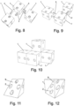
- the building toy has - aside from the components according to examples 1 and 2 - the multiple element 8 , too, depicted on the figures 17 and 18 .
- the multiple element 8 in this example is made by combination of two basic elements 1 placed side by side in such a way that the connecting elements 2 are transitory through the whole body of the multiple element 8 .
- the connecting openings 2 are placed in the same position as is the case in basic elements 1 .
- connecting openings 2 and connecting pins 3 are identical as in the previous examples.
- the derived elements 9 according to figures 11 to 16 are produced by supposed cutting of the body of the basic cube-shaped element 1 . Through various cut surfaces a shape of the triangular prism - or triangular pyramid - was produced, whereby the remnants of the cavities of the connecting openings 2 with the circumferential grooves 12 remain in the body of the derived element 9 .
- Derived elements 9 according to figures 19 and 23 are produced by supposed cutting of the body of the multiple element 8 , which is produced by merger of two basic cube-shaped elements 1 .
- the remnants of both cavities of the connecting openings 2 are maintained, whereby these are cut by the dissection plane alongside their axis.
- these connecting openings 2 are left out and the surface of the dissection plane is smoother and more aesthetically pleasing.
- a building toy according to this example and figures 24 to 26 includes a combined element 10 which is produced by merger of basic element 1 and derived element 9 .
- This combined element 10 allows one to easily create arcs.
- the building toy in this example has, aside from the connecting pins 3 with the length a, a shortened pin 15 and blinding pin 14 , too, as depicted on the figures 27 to 31 . These pins are compatible by the dimensions and shape with other elements of the building toy pursuant to the previous examples.
- the shortened pin 15 has a length which is 3 ⁇ 4 a .
- the blinding pin 14 has a length which is 1 ⁇ 2 a .
- the blinding pin 14 has two flexible segments with the protrusions 13 on one end, whereby the other end is formed by a flat front.
- a tool 11 pursuant to figures 32 to 33 is composed of a flat handle and two pairs of spikes.
- One pair of spikes runs from the flat handle on one side, whereby the spikes are 1 ⁇ 2 a long, and on the other side there are two spikes with a length a.
- the pitch (distance) between the spikes corresponds to the pitch (distance) between the connecting openings 2 on the wall 7 .
- the connecting pins 3 By pushing the spikes of the tool 11 into the connecting openings 2 the connecting pins 3 , are pushed into the half the length of the cavity.
- the other side of the tool 11 pushes the connecting pins 3 out of the cavities of the connecting openings 2 of the basic elements 1 .
- the tool 11 is preferably used during the assembly as well as disassembly.
Landscapes
- Toys (AREA)
- Joining Of Building Structures In Genera (AREA)
Applications Claiming Priority (2)
| Application Number | Priority Date | Filing Date | Title |
|---|---|---|---|
| SK50018-2020U SK9021Y1 (sk) | 2020-02-27 | 2020-02-27 | Stavebnica so základným prvkom a spojovacím kolíkom |
| PCT/IB2021/051572 WO2021171214A1 (en) | 2020-02-27 | 2021-02-25 | Building toy system with basic element and connecting pin |
Publications (3)
| Publication Number | Publication Date |
|---|---|
| EP4110486A1 EP4110486A1 (en) | 2023-01-04 |
| EP4110486B1 true EP4110486B1 (en) | 2024-11-27 |
| EP4110486C0 EP4110486C0 (en) | 2024-11-27 |
Family
ID=72659459
Family Applications (1)
| Application Number | Title | Priority Date | Filing Date |
|---|---|---|---|
| EP21717960.5A Active EP4110486B1 (en) | 2020-02-27 | 2021-02-25 | Building toy system with basic element and connecting pin |
Country Status (7)
| Country | Link |
|---|---|
| US (1) | US12343654B2 (pl) |
| EP (1) | EP4110486B1 (pl) |
| ES (1) | ES3013664T3 (pl) |
| HU (1) | HUE070318T2 (pl) |
| PL (1) | PL4110486T3 (pl) |
| SK (1) | SK9021Y1 (pl) |
| WO (1) | WO2021171214A1 (pl) |
Families Citing this family (6)
| Publication number | Priority date | Publication date | Assignee | Title |
|---|---|---|---|---|
| CN114904285B (zh) * | 2021-02-09 | 2023-09-01 | 第拾四科文化科技(杭州)有限公司 | 一种玩具连接节点模块及拼装玩具 |
| WO2023030598A1 (en) * | 2021-09-02 | 2023-03-09 | Blue Duck Command | Construction system and method for making constructions |
| ES2975695A1 (es) * | 2022-11-22 | 2024-07-11 | Univ Valladolid | Juego de construcción para niños |
| US12440778B2 (en) | 2023-04-14 | 2025-10-14 | Jungle Jim's Accessory Products, Inc. | Framing system for a construction set |
| WO2026018177A1 (en) * | 2024-07-19 | 2026-01-22 | Azzali Giacomo | Assembly kit for removably attaching elements adapted to compose structures |
| EP4643968A1 (en) * | 2024-07-30 | 2025-11-05 | Grzegorz Czekala | A toy building block and a toy construction system |
Family Cites Families (23)
| Publication number | Priority date | Publication date | Assignee | Title |
|---|---|---|---|---|
| GB773652A (en) | 1955-10-21 | 1957-05-01 | Lucian Hopmeier | Improvements in toy building blocks |
| US3165750A (en) * | 1962-11-28 | 1965-01-12 | Tellite Corp | Delay type lens consisting of multiple identical foamed blocks variably loaded by interlinking inserted rods |
| DE1478415A1 (de) | 1962-12-29 | 1969-06-04 | Jacobo Glanzer | Zusammensetzspiel |
| US3685201A (en) | 1971-11-04 | 1972-08-22 | Hieronimus Robert Drieze | Container with a fixed number of elements |
| DE2242046A1 (de) | 1972-08-26 | 1974-02-28 | Lego As | Bauelement fuer bauspielzeuge |
| US3987579A (en) * | 1975-06-09 | 1976-10-26 | Palenik Iii Joseph A | Free-form construction amusement device |
| FR2405730A1 (fr) | 1977-10-13 | 1979-05-11 | Jacquemin Guillaume Philippe | Assemblage en particulier pour jeu de construction |
| US4182072A (en) | 1978-03-09 | 1980-01-08 | Joe Much | Toy construction kit |
| US4283055A (en) * | 1979-10-04 | 1981-08-11 | Larsen Donald R | Puzzle type toy |
| IL61420A (en) | 1980-11-05 | 1984-02-29 | Bril Alexander | Constructional toy kit |
| GB2108857A (en) | 1981-11-07 | 1983-05-25 | Derek David Sudlow | Building toy system |
| US4620747A (en) | 1983-09-23 | 1986-11-04 | Patrick Lemmon | Custom construction system |
| US4547160A (en) * | 1984-08-21 | 1985-10-15 | Richard Labelle | Educational building toy |
| US5152530A (en) * | 1990-03-16 | 1992-10-06 | Dodek Ii Samuel M | Bolt block puzzle apparatus |
| ES2027611A6 (es) | 1991-02-05 | 1992-06-01 | Tri One S L | Juguete para la formacion de cuerpos geometricos a partir de cubos elementales. |
| PL167117B1 (pl) | 1991-05-28 | 1995-07-31 | Zygmunt Piotrowski | Zestaw klockowy PL |
| CZ46U1 (cs) | 1992-11-19 | 1993-02-24 | Radka Čápová | Dětská stavebnice |
| EP0911070A3 (de) | 1997-10-16 | 2000-08-02 | Happy Clown GmbH | Spielbaukasten und Verbindungselement dafür |
| SK2088U (pl) | 1998-10-01 | 1999-02-11 | ||
| US6460850B1 (en) * | 2000-11-17 | 2002-10-08 | Dodek, Ii Samuel M. | Cube puzzle |
| GB2393136B (en) | 2002-09-13 | 2005-04-06 | Timothy John Warner | Construction kit |
| EP3135360A1 (en) | 2015-08-31 | 2017-03-01 | Klaus Heinrich Ehrmann | Toy construction set |
| US20180133614A1 (en) | 2016-11-11 | 2018-05-17 | Joseph Kendall | Elastomeric block system for multi-modal play |
-
2020
- 2020-02-27 SK SK50018-2020U patent/SK9021Y1/sk unknown
-
2021
- 2021-02-25 ES ES21717960T patent/ES3013664T3/es active Active
- 2021-02-25 EP EP21717960.5A patent/EP4110486B1/en active Active
- 2021-02-25 US US17/904,990 patent/US12343654B2/en active Active
- 2021-02-25 PL PL21717960.5T patent/PL4110486T3/pl unknown
- 2021-02-25 WO PCT/IB2021/051572 patent/WO2021171214A1/en not_active Ceased
- 2021-02-25 HU HUE21717960A patent/HUE070318T2/hu unknown
Also Published As
| Publication number | Publication date |
|---|---|
| ES3013664T3 (en) | 2025-04-14 |
| PL4110486T3 (pl) | 2025-04-07 |
| SK9021Y1 (sk) | 2021-02-10 |
| HUE070318T2 (hu) | 2025-05-28 |
| US20230135788A1 (en) | 2023-05-04 |
| EP4110486A1 (en) | 2023-01-04 |
| SK500182020U1 (sk) | 2020-10-02 |
| US12343654B2 (en) | 2025-07-01 |
| EP4110486C0 (en) | 2024-11-27 |
| WO2021171214A1 (en) | 2021-09-02 |
Similar Documents
| Publication | Publication Date | Title |
|---|---|---|
| EP4110486B1 (en) | Building toy system with basic element and connecting pin | |
| CN105263594B (zh) | 建造建筑块和建造玩具 | |
| CA2256428C (en) | Genderless construction system | |
| WO2019196591A1 (zh) | 一种多维度、可正反面自由搭建的积木玩具构筑元件及套件 | |
| EP3305387B1 (en) | Dove-shaped building block | |
| CN201076767Y (zh) | 多功能积木 | |
| US7318764B2 (en) | 3-dimensional assembly | |
| WO2019134476A1 (zh) | 拼接结构件 | |
| ES2731128T3 (es) | Productos de construcción modular y método de ensamblaje de los mismos | |
| CN102740936B (zh) | 自稳定拼图玩具 | |
| KR20210093238A (ko) | 3차원 구조 생성을 위한 구축 시스템 | |
| CN203899150U (zh) | 一种积木及其连接结构 | |
| US10232280B2 (en) | Modular education, entertainment and toy block | |
| US20200222822A1 (en) | Connector with multiple structural interfaces | |
| KR20170065212A (ko) | 탄성벽을 이용한 체결구조를 가지는 디오라마 조립식 블록 | |
| US5040797A (en) | Block puzzle | |
| KR20130029177A (ko) | 결합과 분리가 용이한 3차원 입체블록 | |
| JP2003000963A (ja) | 組立ブロック | |
| KR101137670B1 (ko) | 조립블럭 | |
| JP3180403U (ja) | 組み立てブロック | |
| EP3135360A1 (en) | Toy construction set | |
| TWM531317U (zh) | 積木組 | |
| CN216418301U (zh) | 一种积木结构及形成的积木簇 | |
| JP2017006605A (ja) | 組立ブロックおもちゃ用ジョイント | |
| WO2020144484A1 (en) | 3d tile |
Legal Events
| Date | Code | Title | Description |
|---|---|---|---|
| STAA | Information on the status of an ep patent application or granted ep patent |
Free format text: STATUS: UNKNOWN |
|
| STAA | Information on the status of an ep patent application or granted ep patent |
Free format text: STATUS: THE INTERNATIONAL PUBLICATION HAS BEEN MADE |
|
| PUAI | Public reference made under article 153(3) epc to a published international application that has entered the european phase |
Free format text: ORIGINAL CODE: 0009012 |
|
| STAA | Information on the status of an ep patent application or granted ep patent |
Free format text: STATUS: REQUEST FOR EXAMINATION WAS MADE |
|
| 17P | Request for examination filed |
Effective date: 20220921 |
|
| AK | Designated contracting states |
Kind code of ref document: A1 Designated state(s): AL AT BE BG CH CY CZ DE DK EE ES FI FR GB GR HR HU IE IS IT LI LT LU LV MC MK MT NL NO PL PT RO RS SE SI SK SM TR |
|
| DAV | Request for validation of the european patent (deleted) | ||
| DAX | Request for extension of the european patent (deleted) | ||
| GRAP | Despatch of communication of intention to grant a patent |
Free format text: ORIGINAL CODE: EPIDOSNIGR1 |
|
| STAA | Information on the status of an ep patent application or granted ep patent |
Free format text: STATUS: GRANT OF PATENT IS INTENDED |
|
| INTG | Intention to grant announced |
Effective date: 20240626 |
|
| GRAS | Grant fee paid |
Free format text: ORIGINAL CODE: EPIDOSNIGR3 |
|
| GRAA | (expected) grant |
Free format text: ORIGINAL CODE: 0009210 |
|
| STAA | Information on the status of an ep patent application or granted ep patent |
Free format text: STATUS: THE PATENT HAS BEEN GRANTED |
|
| AK | Designated contracting states |
Kind code of ref document: B1 Designated state(s): AL AT BE BG CH CY CZ DE DK EE ES FI FR GB GR HR HU IE IS IT LI LT LU LV MC MK MT NL NO PL PT RO RS SE SI SK SM TR |
|
| REG | Reference to a national code |
Ref country code: GB Ref legal event code: FG4D |
|
| REG | Reference to a national code |
Ref country code: CH Ref legal event code: EP |
|
| REG | Reference to a national code |
Ref country code: IE Ref legal event code: FG4D |
|
| REG | Reference to a national code |
Ref country code: DE Ref legal event code: R096 Ref document number: 602021022414 Country of ref document: DE |
|
| U01 | Request for unitary effect filed |
Effective date: 20241220 |
|
| U07 | Unitary effect registered |
Designated state(s): AT BE BG DE DK EE FI FR IT LT LU LV MT NL PT RO SE SI Effective date: 20250113 |
|
| REG | Reference to a national code |
Ref country code: CH Ref legal event code: PK Free format text: BERICHTIGUNGEN |
|
| RAP4 | Party data changed (patent owner data changed or rights of a patent transferred) |
Owner name: MASLIK, LUBOMIR |
|
| RIN2 | Information on inventor provided after grant (corrected) |
Inventor name: MASLIK, LUBOMIR |
|
| U1H | Name or address of the proprietor changed after the registration of the unitary effect |
Owner name: MASLIK, LUBOMIR; SK |
|
| U20 | Renewal fee for the european patent with unitary effect paid |
Year of fee payment: 5 Effective date: 20250225 |
|
| PG25 | Lapsed in a contracting state [announced via postgrant information from national office to epo] |
Ref country code: IS Free format text: LAPSE BECAUSE OF FAILURE TO SUBMIT A TRANSLATION OF THE DESCRIPTION OR TO PAY THE FEE WITHIN THE PRESCRIBED TIME-LIMIT Effective date: 20250327 Ref country code: HR Free format text: LAPSE BECAUSE OF FAILURE TO SUBMIT A TRANSLATION OF THE DESCRIPTION OR TO PAY THE FEE WITHIN THE PRESCRIBED TIME-LIMIT Effective date: 20241127 |
|
| REG | Reference to a national code |
Ref country code: ES Ref legal event code: FG2A Ref document number: 3013664 Country of ref document: ES Kind code of ref document: T3 Effective date: 20250414 |
|
| PGFP | Annual fee paid to national office [announced via postgrant information from national office to epo] |
Ref country code: ES Payment date: 20250327 Year of fee payment: 5 Ref country code: HU Payment date: 20250318 Year of fee payment: 5 |
|
| PGFP | Annual fee paid to national office [announced via postgrant information from national office to epo] |
Ref country code: NO Payment date: 20250327 Year of fee payment: 5 |
|
| PGFP | Annual fee paid to national office [announced via postgrant information from national office to epo] |
Ref country code: CH Payment date: 20250307 Year of fee payment: 5 Ref country code: GR Payment date: 20250320 Year of fee payment: 5 |
|
| PGFP | Annual fee paid to national office [announced via postgrant information from national office to epo] |
Ref country code: PL Payment date: 20250306 Year of fee payment: 5 |
|
| PGFP | Annual fee paid to national office [announced via postgrant information from national office to epo] |
Ref country code: SK Payment date: 20250225 Year of fee payment: 5 Ref country code: GB Payment date: 20250225 Year of fee payment: 5 |
|
| PG25 | Lapsed in a contracting state [announced via postgrant information from national office to epo] |
Ref country code: RS Free format text: LAPSE BECAUSE OF FAILURE TO SUBMIT A TRANSLATION OF THE DESCRIPTION OR TO PAY THE FEE WITHIN THE PRESCRIBED TIME-LIMIT Effective date: 20250227 |
|
| REG | Reference to a national code |
Ref country code: GR Ref legal event code: EP Ref document number: 20250400442 Country of ref document: GR Effective date: 20250409 |
|
| REG | Reference to a national code |
Ref country code: SK Ref legal event code: T3 Ref document number: E 46078 Country of ref document: SK |
|
| REG | Reference to a national code |
Ref country code: HU Ref legal event code: AG4A Ref document number: E070318 Country of ref document: HU |
|
| PG25 | Lapsed in a contracting state [announced via postgrant information from national office to epo] |
Ref country code: SM Free format text: LAPSE BECAUSE OF FAILURE TO SUBMIT A TRANSLATION OF THE DESCRIPTION OR TO PAY THE FEE WITHIN THE PRESCRIBED TIME-LIMIT Effective date: 20241127 |
|
| PGFP | Annual fee paid to national office [announced via postgrant information from national office to epo] |
Ref country code: CZ Payment date: 20250226 Year of fee payment: 5 |
|
| PG25 | Lapsed in a contracting state [announced via postgrant information from national office to epo] |
Ref country code: MC Free format text: LAPSE BECAUSE OF FAILURE TO SUBMIT A TRANSLATION OF THE DESCRIPTION OR TO PAY THE FEE WITHIN THE PRESCRIBED TIME-LIMIT Effective date: 20241127 |
|
| PLBE | No opposition filed within time limit |
Free format text: ORIGINAL CODE: 0009261 |
|
| STAA | Information on the status of an ep patent application or granted ep patent |
Free format text: STATUS: NO OPPOSITION FILED WITHIN TIME LIMIT |
|
| 26N | No opposition filed |
Effective date: 20250828 |
|
| PG25 | Lapsed in a contracting state [announced via postgrant information from national office to epo] |
Ref country code: IE Free format text: LAPSE BECAUSE OF NON-PAYMENT OF DUE FEES Effective date: 20250225 |