EP4106567B1 - Garment with adjustable attachment system - Google Patents
Garment with adjustable attachment system Download PDFInfo
- Publication number
- EP4106567B1 EP4106567B1 EP21709150.3A EP21709150A EP4106567B1 EP 4106567 B1 EP4106567 B1 EP 4106567B1 EP 21709150 A EP21709150 A EP 21709150A EP 4106567 B1 EP4106567 B1 EP 4106567B1
- Authority
- EP
- European Patent Office
- Prior art keywords
- garment
- attachment means
- connection portion
- elongated
- holding device
- Prior art date
- Legal status (The legal status is an assumption and is not a legal conclusion. Google has not performed a legal analysis and makes no representation as to the accuracy of the status listed.)
- Active
Links
Images


Classifications
-
- A—HUMAN NECESSITIES
- A41—WEARING APPAREL
- A41D—OUTERWEAR; PROTECTIVE GARMENTS; ACCESSORIES
- A41D13/00—Professional, industrial or sporting protective garments, e.g. surgeons' gowns or garments protecting against blows or punches
- A41D13/0002—Details of protective garments not provided for in groups A41D13/0007 - A41D13/1281
-
- A—HUMAN NECESSITIES
- A41—WEARING APPAREL
- A41D—OUTERWEAR; PROTECTIVE GARMENTS; ACCESSORIES
- A41D13/00—Professional, industrial or sporting protective garments, e.g. surgeons' gowns or garments protecting against blows or punches
- A41D13/0012—Professional or protective garments with pockets for particular uses, e.g. game pockets or with holding means for tools or the like
-
- A—HUMAN NECESSITIES
- A41—WEARING APPAREL
- A41F—GARMENT FASTENINGS; SUSPENDERS
- A41F1/00—Fastening devices specially adapted for garments
-
- A—HUMAN NECESSITIES
- A41—WEARING APPAREL
- A41F—GARMENT FASTENINGS; SUSPENDERS
- A41F9/00—Belts, girdles, or waistbands for trousers or skirts
-
- A—HUMAN NECESSITIES
- A45—HAND OR TRAVELLING ARTICLES
- A45F—TRAVELLING OR CAMP EQUIPMENT: SACKS OR PACKS CARRIED ON THE BODY
- A45F5/00—Holders or carriers for hand articles; Holders or carriers for use while travelling or camping
- A45F5/02—Fastening articles to the garment
-
- A—HUMAN NECESSITIES
- A45—HAND OR TRAVELLING ARTICLES
- A45F—TRAVELLING OR CAMP EQUIPMENT: SACKS OR PACKS CARRIED ON THE BODY
- A45F5/00—Holders or carriers for hand articles; Holders or carriers for use while travelling or camping
- A45F5/1575—Holders or carriers for portable tools
-
- A—HUMAN NECESSITIES
- A41—WEARING APPAREL
- A41D—OUTERWEAR; PROTECTIVE GARMENTS; ACCESSORIES
- A41D2600/00—Uses of garments specially adapted for specific purposes
- A41D2600/20—Uses of garments specially adapted for specific purposes for working activities
Definitions
- the invention relates to a garment, a garment arrangement comprising said garment, and a method connecting at least one attachment means to the garment of the garment arrangement.
- work wear include among others carpenter trousers and work wear jackets.
- a work wear trouser comprises several loops and pockets, to support and hold such tools and/or gear.
- Some work wear are modular, such that pockets and protective knee pads may be detachable from the trouser using zippers or hook-and-loop fasteners.
- An example of such carpenter trouser is disclosed in EP1316262A1 .
- such trousers lack holding devices for large and heavy instruments and there is often a need for more pockets with variable sizes and of different types than those present in a carpenter trouser.
- a third option is to attach a tool holder to an ordinary belt threaded through belt loops, and then fasten the instrument to the tool holder.
- the belt loops of the trousers may be in the way when the user wishes to adjust the position of the tools/instruments fastened along a belt passed through the belt loops.
- US 2015/033446 A1 shows a cold-proof trouser having a first band part and a second band part, each provided with a first subrail part and second subrail part, respectively.
- the first and second subrail parts are each configured to be releasably connected to a first and second engagement part of a suspender, respectively.
- the above and other objects of the invention are achieved, in full or at least in part, by a garment as defined by claim 1.
- a garment is a trouser comprising a waistband, and the garment has an elongated garment portion provided with at least one garment connection portion and a base.
- the garment connection portion is configured to be releasably connected to an attachment means, and the garment connection portion further comprises a projecting part extending from the base of said elongated garment portion and a connection element being arranged at a remote end of said projecting part.
- the elongated garment portion extends laterally around and along the waistband of said trouser, and the projecting part is in the form of a strap or flange having an adjacent end and the remote end and is movable towards and away from the base.
- a garment arrangement comprising the garment according to claim 1, and an attachment means configured to be releasably connected to the garment connection portion.
- the attachment means is configured to be movable along the extension of the elongated garment portion. This is advantageous in that it will cause the attachment means to be arranged at a preferable position when the attachment means is connected to the garment connection portion.
- the garment arrangement further comprises a gear holding device and the attachment means is configured to be connected to the gear holding device.
- the attachment means is connected to the gear holding device by screws, bolts, rivets, stitches or an adhesive. This is beneficial since the attachment means provides flexibility for the user to choose different number of attachment means and thus different types or number of gear holding devices. Various numbers of attachment means may be used, and the user can adapt the number and type of gear holding device depending on present needs.
- Each gear holding device may in turn be fastened using one or several attachment means, which make the gear holding device securely releasably attachable to the garment.
- the connection element is in the form of a rail.
- connection element is configured to slidingly and releasably engage an attachment member of the attachment means.
- attachment member is a clutch with a clutch cavity and a clutch opening.
- the clutch opening is configured to hold the connection element, which may be inserted in the clutch through the clutch opening.
- the gear holding device is connected to the attachment means through a mating fixation part engaging a fixation end of the attachment means.
- the mating fixation part is connected to the gear holding device by screws, bolts, rivets, stitches or an adhesive. This is advantageous in that the attachment means can be left connected to the elongated garment portion when the gear holding device is removed.
- the gear holding device is a tool holder, a loop, a pocket or an advanced pocket having a plurality of sub-pockets, loops and/or tool holders. This is beneficial since it may provide the garment with different sorts of instrument holders such that the garment becomes modular and can be adapted to various uses.
- the elongated garment portion is arranged and extends along a width W of the garment.
- the elongated garment portion is arranged and extends along the waistband of the trouser.
- connection element is in the form of a rail and the attachment means comprises an attachment member configured to releasably slidingly engage the rail.
- attachment member can be threaded onto the rail sideways and slide along the rail and be arranged at a position which is preferred by the user.
- the rail has a substantially circular cross-section.
- the rail has a substantially rectangular cross-section.
- the attachment member is a type of clutch, having a clutch opening and a clutch cavity.
- the garment connection portion and parts thereof are made of textile parts.
- the garment connection portion is made of a material comprising nylon. This is advantageous since such materials can provide high strength and are durable and can resist wear.
- they may provide a surface structure that causes friction between the attachment member and the textile such that the attachment means will be movable along the garment connection portion but undesirable sliding along the garment connection portion and the elongated garment portion is prevented.
- the garment is a work wear garment. This is advantageous since the garment arrangement provides the work wear garment with a broad flexibility in terms of adapting the work wear for different craftsmen and different uses.
- a method for connecting at least one attachment means to an elongated garment portion of a garment arrangement comprises the steps of providing a garment being a trouser comprising a waistband, the garment has an elongated garment portion provided with at least one garment connection portion and a base, and wherein the elongated garment portion extends laterally around and along the waistband of said trouser; providing the attachment means, releasably connecting the attachment means to the garment connection portion, and adjusting the attachment means to a preferred position along the garment connection portion.
- the garment connection portion further comprises a projecting part extending from the base of the elongated garment portion, where the projecting part is in the form of a strap or flange having an adjacent end and a remote end and being movable towards and away from the base, and a connection element being arranged at a remote end of the projecting part.
- the method further comprises the step of connecting a mating fixation part to a fixation end of said attachment means.
- the fixation part is connected to a gear holding device.
- the method further comprises a step of putting on the work wear garment before the steps of releasably connecting the attachment means to the garment connection portion and adjusting the attachment means to a preferred position along the garment connection portion.
- the step of connecting the mating fixation part to the fixation end of said attachment means is conducted before the step of adjusting the attachment means to a preferred position along the garment connection portion.
- the present disclosure relates to garment arrangements in particular trousers, comprising a connection system 1000, 2000 (shown in Figs 1d , 3b , 6b and 7b ) for releasably attachable tool holders and pockets, or any other feature desirable for a garment, for instance protective gear such as knee or elbow pads.
- the connection system 1000, 2000 is also referred to as a garment arrangement 1000, 2000 or a releasable adjustable attachment system 1000, 2000 herein.
- the garments may be for instance a work wear garment or a sportswear garment. Work wear may relate to wear worn by for instance craftsmen, construction builders, carpenters, industry workers, fire fighters, police officers, plumbers, different kind of guards et.c. It may be indoor wear or outdoor wear.
- FIGs. 1a-1d and Figs. 2a-c work wear garments 100, 200 are shown.
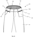
- Figs. 1a-c show a trouser 100 having a pair of legs 101, a plurality of belt loops 102 and a waist fabric mesh 105.
- the trouser 100 has a width W extending along a lateral direction, whereas the legs 101 have a length L extending in a longitudinal direction indicated by the arrow in Fig. 1a .
- the trouser 100 in Figs. 1a-d comprises an elongated garment portion 110.
- the elongated garment portion 110 extends laterally around and along a waistband 115 of said trouser 100.
- Fig. 1a shows a front view of the trouser 100
- Fig. 1b shows a rear view of the trouser 100
- Fig. 1c shows a side view of the trouser 100.
- the trouser 100 may also comprise a plurality of separate elongated garment portions 110 portioned along the waistband 115, or arranged elsewhere on the trousers 100, such as for instance in the thigh area, around the knees or in the area by the calves.
- a gear holding device 120 has been releasably attached to the elongated garment portion 110.
- the gear holding device 120 is a pocket.
- the gear holding device 120 may be another type of device, such as a tool holder, a loop, an advanced tool pocket having a plurality of smaller pockets, loops and/or tool holders integrated therein, or any other instrument holder useful for a user.
- the connection system 1000 between the elongated garment portion 110 and the gear holding device 120 will be explained in more detail with reference to Figs. 3a-7b .
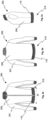
- Figs. 2a-c show a jacket 200, which is not part of the invention, comprising two arms 201, a torso portion 205 and a waistband 215.
- An elongated garment portion 110 of the same configuration as the elongated garment portion 110 shown in Figs. 1a-d is also comprised in the jacket 200 along a width W of the waistband 115. Said width W is indicated by the arrow in Fig. 2a .
- the elongated garment portion 110 extends laterally around and along the waistband 115.
- the elongated garment portion 110 is configured to receive and releasably connect a gear holding device 120 as shown in Figs. 1d and 5b .
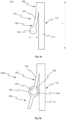
- FIG. 3a An enlarged view of a longitudinal cross-section A-A (indicated in Fig. 4b ) of the elongated garment portion 110 is shown in Fig. 3a .
- the longitudinal direction L is indicated by a double-faced arrow in Fig. 3a .
- the cross-section A-A is taken perpendicularly to the longitudinal direction L and the width W (shown in Fig. 4b ).
- the elongated garment portion 110 comprises a garment connection portion 150, which in turn comprises a connection element 152 and a projecting part 154 extending from a base 111 of the elongated garment portion 110.
- the projecting part 154 is in the form of a strap or flange 154 having an adjacent end 156 and a remote end 158.
- the projecting part 154 shown in Fig. 3a and 3b is movable towards and away from the base 111 as indicated by the double-faced arrow in Fig. 3a placed below the connection element 152.
- the connection element 152 is in the form of a rail 152 in Figs 3a and 3b .
- an attachment means 160 has been releasably connected to the connection element 152 and the parts form a releasable adjustable attachment system 1000.
- the attachment means 160 comprises an attachment member 162, which in Fig. 3b is in the form of a clutch 162.
- the clutch 162 detachably engages the connection element 152.
- the connection element 152 has been threaded into a cavity 164 of the clutch 162 through a clutch opening 163.
- Fig. 4a shows the connection mechanism shown in Figs. 3a and 3b in a front view.
- Fig. 4b shows an isometric view of the connection mechanism shown in Figs. 3a-4a .
- the attachment means 160 comprises the clutch 162, which is releasably attached to the rail 152, arranged on the projecting part 154 of the garment connection portion 150. From the clutch 162 extends an attachment portion 165, which has a fixation end 168 configured to either be attached to a mating fixation part (for instance as shown in Figs 8a-8c ) or being directly attached to the gear holding device 120 (as shown in Fig. 1d or 5b ), for instance by screws, rivet and/or by the use of an adhesive or sowing.
- a mating fixation part for instance as shown in Figs 8a-8c
- the gear holding device 120 as shown in Fig. 1d or 5b
- two attachment means 160 have been releasably coupled to the connection element 152 of the elongated garment portion 110 (the base 111 is not visible in the Figure 5a as the projecting part 154 covers the base 111).
- Two attachment means 160 is beneficial to use for larger and/or broader gear holding devices 120, such as the pocket shown in Fig. 5b .
- the attachment means 160 have been adjusted along the extension of the rail 152 to fit the pocket 120, which has been attached to the attachment means 160.
- connection system 1000 shown in Figs. 3a-5b has several advantages. First of all, the connection system of Figs. 3a to 5b is slender against the trouser 100. This is due to the design of the rail 152 and the flange 154 which prevents the formation of a certain thickness. In addition, the attachment means 160 may be designed to be thinner since the connection portion 150 in the trouser 100 will be arranged above (in a longitudinal direction) the attachment means 160 of the gear holding device 120.
- the longitudinal position on the trouser 100 is also beneficial, since it is arranged just below the waistband 115, which enables the use of an ordinary belt if needed, and the pocket 120 will be arranged in a favourable position.
- FIG. 6a a different version of the releasable adjustable attachment system 1000 is shown.
- An enlarged view of a longitudinal cross-section of the elongated garment portion 110 is shown in Fig. 6a .
- the longitudinal direction L is indicated by the double-faced arrow in Fig. 6a .
- the elongated garment portion 110 comprises a garment connection portion 150, which in turn comprises a connection element 152 and a projecting part 154 extending from a base 111 of the elongated garment portion 110.
- the projecting part 154 is in the form of a protrusion 154 having an adjacent end 156 and a remote end 158.
- an attachment means 160 has been releasably connected to the connection element 152.
- the attachment means 160 comprises an attachment member 162, which in Fig. 6b is, similarly to the attachment member of Fig. 3b , in the form of a clutch 162.
- the clutch 162 detachably engages the connection element 152.
- the connection element 152 has been threaded into a cavity 164 of the clutch 162 through a clutch opening 163.
- connection element 152 of Figs. 3a-6b is in the form of a rail 152 extending laterally along the elongated garment portion 110.
- the rail 152 has a substantially circular cross-section.
- the cross-section shape of such connection element 152 may be in another geometrical shape enabling the releasable connection of the attachment means 160 to the connection element 152.
- a garment connection portion 250 of another embodiment is shown in Figs. 7a and 7b as an enlarged longitudinal cross-section.
- the longitudinal direction L is indicated by the double-faced arrow in Fig. 7a .
- the elongated garment portion 210 comprises the connection portion 250 which is provided with a projecting part 254 and a connection element 252, which is in the form of a plate like member 252.
- the projecting part 254 extends from a base 211 of the elongated garment portion 210.
- the projecting part 254 is in the form of a block 254 having an adjacent end 256 and a remote end 258.
- the garment connection portion 250 is a type of rail extending laterally along the elongated garment portion 210, and has a rectangular longitudinal cross-section.
- an attachment means 260 has been releasably connected to the plate like member 252 and together form a releasable adjustable attachment system 2000, also referred to as a garment arrangement 2000 herein.
- the attachment means 260 comprises an attachment member 262, which in Fig. 7b is in the form of a clutch 262 having a rectangular cross-section.
- the clutch 262 detachably engages the connection element 252, in the form of the plate like member 252.
- the connection element 252 has been threaded into a cavity 264 of the clutch 262 through a clutch opening 263.
- the fixation end 168, 268, 368 may comprise a magnet to improve the connection properties between the attachment means 160, 260 and the gear holding device 120. Further, the fastening between the fixation end 168, 268, 368 and a mating fixation part (shown in Figs 8a-8c ) or a gear holding device 120 may be in the form of a known coupling mechanism known in the art, or such as a fastening mechanism disclosed with reference to Figs 8a and 8b .
- the attachment means 160, 260 is connected directly to the gear holding device 120.
- the attachment means 160, 260 may be sown or glued to the gear holding device 120.
- the attachment means 160, 260 connected directly to the gear holding device 120 is attached for instance by screws, an adhesive, stitches, rivets and/or vulcanization.
- the releasable adjustable attachment systems 1000, 2000 shown in Figs 6b and 7b may further comprise an attachment portion 165, 265 and which has a fixation end 168 configured to either be attached to a mating fixation part (as for instance shown in Figs 8a-8c ) or being directly attached to a gear holding device 120 as described with reference to Figs. 4a and 4b .
- the gear holding device 120 may be attached to a mating fixation part 370 (shown in Fig. 8a ), the gear holding device 120 may be connected to the mating fixation part 370 for instance by screws, bolts, screw-nuts, an adhesive, stitches, rivets or vulcanization.
- the gear holding device 120 could further be connected to the mating fixation part 370 using a plurality of the above attachment means, for example a combination of adhesive and stitches.
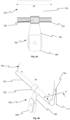
- FIG. 8a to 8d An example of a fastening mechanism between a mating fixation part 370 and an exemplary attachment means 360 is shown in Figs 8a to 8d .
- the attachment means 360 shown in Figs 8b and 8d is provided with (similarly to the attachments devices 160, 260 shown in Figures 3a to 7b ) a clutch 362 having a cavity 364.
- the clutch 362 is configured to engage and hold a connection element 152, 252 of a elongated garment portion 110, 210.
- the attachment means 360 comprises a locking recess 369 arranged on a fixation end 368 of an attachment portion 365.
- the mating fixation part 370 in Fig. 8a is facing the attachment means 360 in Fig. 8b in the configuration which they fit together.
- the mating fixation part 370 shown in Figs 8a and 8c is provided with holes 372 which can be used to fasten the fixation part 370 to a gear holding device 120 with for instance screws and screw-nuts.
- the fixation part 370 has a connection recess 378 configured to slidingly engage and house the fixation end 368 of the attachment means 360.
- a locking protrusion 379 is arranged within the connection recess 378 and is configured to fit into the locking recess 369 of the fixation end 368 when the fixation part 370 and the attachment means 360 are connected to each other.
- the lock release button 379' is provided with a cord hole 379" through which for instance a string can be threaded such that the lock release button 379' can be pulled outwards, perpendicularly from the surface of the mating fixation part 370.
- the fixation end 368 is placed in contact with a side surface 371 of the fixation part 370, and the fixation end 368 is slidingly pushed into the connection recess 378.
- the lock release button 379' laterally and pushes the fixation part 370 upwards in the direction indicated by the arrows in Figs 8a and 8c .
- the lock release button 379' is pulled, the locking protrusion 379 will be moved out of the locking recess 369 and the mating fixation part 370 will be able to be slidingly released from the engagement between the fixation end 368 and the connection recess 378.
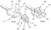
- FIGs 9a to 9c Another example of a fastening mechanism between a mating fixation part 470 and an exemplary attachment means 460 is shown in Figs 9a to 9c .
- the attachment means 460 and the mating fixation part 470 are shown separated from each other.
- the attachment means 460 is connected to the mating fixation part 470
- the attachment means 460 and the mating fixation part 470 are shown separated from each other while the mating fixation part 470 is shown in an exploded view.
- the attachment means 460 shown in Figs 9a-9c is similar to the attachments devices 160, 260 shown in Figures 3a to 7b and the attachment means 360 in Figs 8b and 8d .
- the attachment means 460 shown in Figs 9a-9c is provided a clutch 462 having a cavity 464.
- the clutch 462 is configured to engage and hold a connection element 152, 252 of an elongated garment portion 110, 210.
- the attachment means 460 comprises a locking flange 469 arranged on an attachment portion 465, and a fixation end 468, in the form of a locking waist 468.
- the mating fixation part 470 shown in Fig. 9c is provided with holes 471b which can be used to fasten the fixation part 470 to a gear holding device 120 with rivets 572 (or for instance screws and screw-nuts). Moreover, the mating fixation part 470 has a connection recess 478 configured to slidingly engage and house the attachment portion 465 of the attachment means 460, as shown in Fig. 9b .
- the mating fixation part 470 shown in Fig. 9c is provided with a handle portion 480 comprising a grip 481 and a handle 482.
- the grip 481 is mated to the handle 482 through a loop in the handle 482.
- the handle 482 further comprises two elastic members 483.
- the elastic member may be in the form of a spring.
- Fig. 9c shows a locking mechanism of the fixation part 470, used to attach the attachment means 460 to the fixation part 470.
- the locking flange 469 of the attachment portion 465 is placed in contact with a base side surface 471 of the fixation part 470, and the attachment portion 465 is slidingly pushed into the connection recess 478.
- a locking ring 479 is arranged within the connection recess 478 and is configured to enclose the locking waist 468 of the attachment portion 465 when the fixation part 470 and the attachment means 460 are connected to each other.
- the locking ring 479 has two locking ring ends 479a, 479b.
- the locking ring 479 is made of a flexible material, such as a flexible metal material or a flexible plastic material.
- the distance between the locking ring ends 479a, 479b is smaller than the width the locking waist 468.
- Inner edges 472a of the fixation part upper portion 472 of the fixation part 470 prevents the locking ring 479 from expanding, since the locking ring ends 479a, 479b abut the inner edges 472a of the upper portion 472.
- the locking flange 469 slides beneath the locking ring 479, and the locking waist 468 will exert force on the locking ring 479.
- the elastic members (in this case, springs) 483 will be compressed and the locking ring 479 is moved towards the loop in the handle 482.
- the locking ring 479 is moved upwards the locking ring ends 479a, 479b pass the inner edges 472a, and the locking ring 479 expand, resulting in more space between the locking ring ends 479a, 479b such that there is room for the locking waist 468.
- the locking ring 479 then snaps back around the locking waist 468 and engage the locking waist 468. If the user tries to pull and detach the attachment means 460 from the fixation part 470, the locking ring ends 479a, 479b cannot expand since the inner edges 472a lock the position of the locking ring 479.In the attached position, stabilisers 471a on the base side surface 471 hold the attachment means 460 in a stable position.
- the locking waist 468 has substantially straight side edges which will abut the stabilisers 471a when the attachment means 460 is connected to the fixation part 470.
- the user pulls the grip 481 and/or handle 482 such that the springs 483 are compressed and the locking ring 479 is moved towards the handle 482. In this position, the locking ring ends 479a, 479b have room for expansion inside the fixation part 470.
- the distance between the locking ring ends 479a, 479b is larger than the width of the locking waist 468, and the attachment means 460 may be pulled out from the connection recess 478.
- the attachment means 460 can be pulled and disconnected from the fixation part 470.
- a locking mechanism for a fixation part 470 configured to attach an attachment means 460 to said fixation part 470.
- the locking mechanism comprises a handle 482 with at least one elastic member 483.
- the locking mechanism comprises a locking ring 479 configured to engage the attachment means 460.
- the elastic member 483 may be in the form of a spring.
- the locking ring 479 has two locking ring ends 479a, 479b.
- the locking ring 479 does not have room for expansion when the elastic member 483 is in its relaxed state.
- a distance between said two locking ring ends 479a, 479b is smaller than a width of the attachment means 460 when the elastic member 483 is in its relaxed state.
- a distance between said two locking ring ends 479a, 479b is larger than a width of the attachment means 460 when the elastic member 483 is in its compressed state.
- the locking ring 479 has room for expansion in the fixation art 470 when the elastic member 483 is in its compressed state.
- the two locking ring ends 479a, 479 abut inner edges 472a of the fixation part 470 when the elastic member 483 is in its relaxed state, preferably the inner edges 472a being inner edges of a fixation part upper portion 472 of the fixation part 470. More preferably, the locking ring ends 479a, 479b cannot expand when the elastic member 483 is in its relaxed state since the inner edges 472a lock the position of the locking ring 479.
- the attachment means 160, 260, 360, 460 and the mating fixation part 370, 470 may be made of a plastic material, or a metal.
- All attachment means 160, 260, 360, 470 disclosed herein may be adjusted along the extension of the connection element 152, 252 disclosed herein. In that way, the user can easily adjust the work wear garment 100, 200 to fit a particular use.
- the attachment means 160, 260, 360, 460 provide flexibility for the user to choose different number of attachment means 160, 260, 360, 460 and different gear holding devices 120.
- Various numbers of attachment means 160, 260, 360, 460 may be used, and the user can adapt the number and type of gear holding device 120 depending on present needs.
- Each gear holding device 120 may in turn be fastened using one or several attachment means 160, 260, 360, 460 such as two attachment means 160, 260, 360, 460 (shown in Fig. 5b ), or three or four attachment means 160, 260, 360, 460 (not shown).
- the attachment means 160, 260, 360, 460 are simple to detach for the user, while ensuring a secure fixation of the gear holding devices 120 during use.
- the garment 100, 200 is modular and may be adapted for several purposes on a daily basis.
- the gear holding devices 120 and the attachment means 160, 260, 360, 460 may be released from the garment connection portion 150, 250 for instance for washing of the garment 100, 200 and may be exchanged in the event of damages.
- An end of the elongated garment portion 110, 210 may comprise a locking feature (not shown), such that the attachment means 160, 260, 360, 460 cannot slide off the elongated garment portion 110, 210.
- a locking feature may for instance be a flange releasably connectable by a snip-fit button such that is covers the end of the elongated garment portion 110, 210 in a closed state.
- the garment connection portion 150, 250 may be made of a woven or nonwoven material.
- garment connection portion 150, 250 is made of a material comprising nylon, such as Cordura fabric or Kevlar, an ultra-high-molecular-weight polyethylene (UHMWP), such as Dyneema cord or Spectra, or a combination thereof.
- UHMWP ultra-high-molecular-weight polyethylene
- the garment connection portion 150, 250 may also be formed of a plastic or comprise a metal, such as a steel rail.
- the elongated garment portion 110, 210 is a strap, which may be attached to and integrated in said garment 100, 200.
- the garment arrangement 1000, 2000 comprises a garment 100, 200, and the strap which is provided with a strap connection portion and which is at least partly integrated within or attached to the garment 100, 200.
- the garment arrangement 1000, 2000 also comprises an attachment means 160 configured to be releasably connected to the strap connection portion.
- the attachment means 160 is configured to be movable along the extension of the strap.
- the method 500 shown in Fig. 10a comprises an optional first step of putting on 510 the garment 100, 200.
- the method is followed by a step of providing 520 a garment 100, 200 having an elongated garment portion 110, 210 provided with at least one garment connection portion 150, 250.
- the attachment means 160, 260, 360, 460 is provided 530 and the attachment means 160, 260, 360, 460 is releasably connected 540 to the garment connection portion 150, 250 and is adjusted 550 to a preferred position along the garment connection portion 150, 250.
- the next step involves releasably connecting 560 the mating fixation part 370 to the fixation end 368 of the attachment means 160, 260, 360, 460.
- the fixation part 370 is connected to the gear holding device 120.
- FIG. 10b Another method 500' is disclosed in Fig. 10b .
- the method discloses an optional step of firstly putting on 510 the garment 100, 200. Further, in this method the step of connecting 560 the mating fixation part 370, 470 to the fixation end 368 or locking waist 468 of said attachment means 160, 260, 360, 460 is conducted before the step of adjusting 550 the attachment means 160, 260, 360, 460 to a preferred position along the garment connection portion 150, 250.
- the garment connection portion 150, 250 When attaching the attachment means 160, 260, 360, 460 to the garment connection portion 150, 250, the garment connection portion 150, 250 is fitted into the cavity 164, 264, 364, 464 of the clutch 162, 262, 362, 462 from a lateral direction.
Landscapes
- Engineering & Computer Science (AREA)
- Textile Engineering (AREA)
- Health & Medical Sciences (AREA)
- General Health & Medical Sciences (AREA)
- Physical Education & Sports Medicine (AREA)
- Slide Fasteners (AREA)
- Outer Garments And Coats (AREA)
- Orthopedics, Nursing, And Contraception (AREA)
- Professional, Industrial, Or Sporting Protective Garments (AREA)
- Details Of Garments (AREA)
Description
- The invention relates to a garment, a garment arrangement comprising said garment, and a method connecting at least one attachment means to the garment of the garment arrangement.
- Craftsmen in different technical fields, for instance carpenters, often use work wear and protective garments during labour to prevent the occurrence of injuries and to have easy access to different tools and working gear. Such work wear include among others carpenter trousers and work wear jackets.
- Typically, a work wear trouser comprises several loops and pockets, to support and hold such tools and/or gear. Some work wear are modular, such that pockets and protective knee pads may be detachable from the trouser using zippers or hook-and-loop fasteners. An example of such carpenter trouser is disclosed in
EP1316262A1 . However, such trousers lack holding devices for large and heavy instruments and there is often a need for more pockets with variable sizes and of different types than those present in a carpenter trouser. - Therefore, many craftsmen use tool belts, provided with more robust tool holding devices, such as the belts disclosed in
US20040065709A1 orUS20140166516A1 . Preferably such belts have tool holders which may be adjustable along the extension of the belt. However, such belt has the disadvantage that the belt has to be worn on the outside of a work trouser and the belt may slide around the waist of the user due to uneven loading or different weight of the tools held in the belt. Further, these belts are often adapted after the craftsmen in need of most equipment, rendering the tool belt unnecessarily bulky and ungainly for several users. In addition, the tool holders themselves may move along the belt when the craftsman is working. - A third option is to attach a tool holder to an ordinary belt threaded through belt loops, and then fasten the instrument to the tool holder. However, with this solution, the belt loops of the trousers may be in the way when the user wishes to adjust the position of the tools/instruments fastened along a belt passed through the belt loops.
- Further prior art is disclosed in
US 2015/033446 A1 , which shows a cold-proof trouser having a first band part and a second band part, each provided with a first subrail part and second subrail part, respectively. The first and second subrail parts are each configured to be releasably connected to a first and second engagement part of a suspender, respectively. - Hence, there is a need for an improved work wear which overcome these problems.
- According to a first aspect of the invention, the above and other objects of the invention are achieved, in full or at least in part, by a garment as defined by claim 1. According to this claim the above object is achieved by a garment. The garment is a trouser comprising a waistband, and the garment has an elongated garment portion provided with at least one garment connection portion and a base. The garment connection portion is configured to be releasably connected to an attachment means, and the garment connection portion further comprises a projecting part extending from the base of said elongated garment portion and a connection element being arranged at a remote end of said projecting part. The elongated garment portion extends laterally around and along the waistband of said trouser, and the projecting part is in the form of a strap or flange having an adjacent end and the remote end and is movable towards and away from the base.
- According to a second aspect of the invention, there is provided a garment arrangement, comprising the garment according to claim 1, and an attachment means configured to be releasably connected to the garment connection portion. The attachment means is configured to be movable along the extension of the elongated garment portion. This is advantageous in that it will cause the attachment means to be arranged at a preferable position when the attachment means is connected to the garment connection portion.
- According to a first embodiment, the garment arrangement further comprises a gear holding device and the attachment means is configured to be connected to the gear holding device. Preferably the attachment means is connected to the gear holding device by screws, bolts, rivets, stitches or an adhesive. This is beneficial since the attachment means provides flexibility for the user to choose different number of attachment means and thus different types or number of gear holding devices. Various numbers of attachment means may be used, and the user can adapt the number and type of gear holding device depending on present needs. Each gear holding device may in turn be fastened using one or several attachment means, which make the gear holding device securely releasably attachable to the garment. Preferably, the connection element is in the form of a rail. Further optionally, the connection element is configured to slidingly and releasably engage an attachment member of the attachment means. In one embodiment, the attachment member is a clutch with a clutch cavity and a clutch opening. The clutch opening is configured to hold the connection element, which may be inserted in the clutch through the clutch opening.
- According to a second embodiment, the gear holding device is connected to the attachment means through a mating fixation part engaging a fixation end of the attachment means. Preferably, the mating fixation part is connected to the gear holding device by screws, bolts, rivets, stitches or an adhesive. This is advantageous in that the attachment means can be left connected to the elongated garment portion when the gear holding device is removed.
- According to another embodiment, the gear holding device is a tool holder, a loop, a pocket or an advanced pocket having a plurality of sub-pockets, loops and/or tool holders. This is beneficial since it may provide the garment with different sorts of instrument holders such that the garment becomes modular and can be adapted to various uses.
- According to yet another embodiment, the elongated garment portion is arranged and extends along a width W of the garment. The elongated garment portion is arranged and extends along the waistband of the trouser.
- According to another embodiment, the connection element is in the form of a rail and the attachment means comprises an attachment member configured to releasably slidingly engage the rail. This is beneficial since the attachment member can be threaded onto the rail sideways and slide along the rail and be arranged at a position which is preferred by the user.
- According to another embodiment, the rail has a substantially circular cross-section.
- According to one embodiment, the rail has a substantially rectangular cross-section.
- According to yet another embodiment, the attachment member is a type of clutch, having a clutch opening and a clutch cavity.
- According to another embodiment, the garment connection portion and parts thereof are made of textile parts. Preferably, the garment connection portion is made of a material comprising nylon. This is advantageous since such materials can provide high strength and are durable and can resist wear. In addition, they may provide a surface structure that causes friction between the attachment member and the textile such that the attachment means will be movable along the garment connection portion but undesirable sliding along the garment connection portion and the elongated garment portion is prevented.
- According to yet another embodiment, the garment is a work wear garment. This is advantageous since the garment arrangement provides the work wear garment with a broad flexibility in terms of adapting the work wear for different craftsmen and different uses.
- According to a third aspect, there is provided a method for connecting at least one attachment means to an elongated garment portion of a garment arrangement. The method comprises the steps of providing a garment being a trouser comprising a waistband, the garment has an elongated garment portion provided with at least one garment connection portion and a base, and wherein the elongated garment portion extends laterally around and along the waistband of said trouser; providing the attachment means, releasably connecting the attachment means to the garment connection portion, and adjusting the attachment means to a preferred position along the garment connection portion. The garment connection portion further comprises a projecting part extending from the base of the elongated garment portion, where the projecting part is in the form of a strap or flange having an adjacent end and a remote end and being movable towards and away from the base, and a connection element being arranged at a remote end of the projecting part.
- In one embodiment, the method further comprises the step of connecting a mating fixation part to a fixation end of said attachment means. The fixation part is connected to a gear holding device.
- In another embodiment, the method further comprises a step of putting on the work wear garment before the steps of releasably connecting the attachment means to the garment connection portion and adjusting the attachment means to a preferred position along the garment connection portion.
- In one embodiment, the step of connecting the mating fixation part to the fixation end of said attachment means is conducted before the step of adjusting the attachment means to a preferred position along the garment connection portion.
- Other objectives, features and advantages of the present invention will appear from the following detailed disclosure, from the attached claims, as well as from the drawings.
- Generally, all terms used in the claims are to be interpreted according to their ordinary meaning in the technical field, unless explicitly defined otherwise herein. All references to "a/an/the [element, device, component, means, step, etc.]" are to be interpreted openly as referring to at least one instance of said element, device, component, means, step, etc., unless explicitly stated otherwise. The steps of any method disclosed herein do not have to be performed in the exact order disclosed, unless explicitly stated.
- As used herein, the term "comprising" and variations of this term are not intended to exclude other additives, components, integers or steps.
- By way of example, embodiments of the present disclosure will now be described with reference to the accompanying drawings, in which:
-
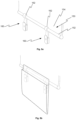
Figure 1a-c shows a work wear trouser in a front view, a rear view and a side view, respectively; -
Figure 1d shows a portion of the work wear trouser shown inFigs 1a-c having a pocket releasably attached thereto; -
Figure 2a-c shows a work wear jacket, which is not part of the invention, in a front view, a rear view and a side view respectively; -
Figure 3a shows a longitudinal cross-section of an elongated garment portion comprising a connection portion disclosed herein; -
Figure 3b shows the longitudinal cross-section of an elongated garment portion comprising the connection portion ofFig. 3a , having an attachment means releasably connected thereto; -
Figure 4a shows a front view of the elongated garment portion having an attachment means releasably connected thereto shown inFig 3b ; -
Figure 4b shows an isometric view of the elongated garment portion having an attachment means releasably connected thereto shown inFig 3b ; -
Figure 5a shows an isometric view of the elongated garment portion having two attachment means releasably connected thereto; -
Figure 5b shows an isometric view of the elongated garment portion having two attachment means releasably connected thereto being connected to a pocket; -
Figure 6a shows a longitudinal cross-section of an elongated garment portion of another embodiment comprising a connection portion disclosed herein; -
Figure 6b shows the longitudinal cross-section of the elongated garment portion comprising the connection portion ofFig. 6a , having an attachment means releasably connected thereto; -
Figure 7a shows a longitudinal cross-section of an elongated garment portion of yet another embodiment comprising a connection portion disclosed herein; -
Figure 7b shows the longitudinal cross-section of the elongated garment portion comprising the connection portion ofFig. 7a , having an attachment means releasably connected thereto; -
Figures 8a-d show an attachment means, and a mating fixation part; -
Figures 9a-c show an attachment means, and a mating fixation part; and -
Figures 10a-b are flowcharts illustrating methods for attaching a gear holding device to a garment. - Embodiments of the present disclosure will be described in more detail below with reference to the accompanying drawings in order for those skilled in the art to be able to carry out the invention. The invention may, however, be embodied in many different forms and should not be construed as limited to the embodiments set forth herein. Rather, these embodiments are provided so that this disclosure will be thorough and complete, and will fully convey the scope of the invention to those skilled in the art. The scope of protection of the invention is defined by the appended patent claims. Furthermore, the terminology used in the detailed description of the particular embodiments illustrated in the accompanying drawings is not intended to be limiting of the invention.
- Embodiments of the present disclosure will now be described below with reference to
Figs. 1a to 8c . - The present disclosure relates to garment arrangements in particular trousers, comprising a
connection system 1000, 2000 (shown inFigs 1d ,3b ,6b and7b ) for releasably attachable tool holders and pockets, or any other feature desirable for a garment, for instance protective gear such as knee or elbow pads. Theconnection system garment arrangement adjustable attachment system - With reference to
Figs. 1a-1d andFigs. 2a-c , work weargarments Figs. 1a-c show atrouser 100 having a pair oflegs 101, a plurality ofbelt loops 102 and awaist fabric mesh 105. Thetrouser 100 has a width W extending along a lateral direction, whereas thelegs 101 have a length L extending in a longitudinal direction indicated by the arrow inFig. 1a . - In addition, the
trouser 100 inFigs. 1a-d comprises anelongated garment portion 110. Theelongated garment portion 110 extends laterally around and along awaistband 115 of saidtrouser 100.Fig. 1a shows a front view of thetrouser 100,Fig. 1b shows a rear view of thetrouser 100 andFig. 1c shows a side view of thetrouser 100. Thetrouser 100 may also comprise a plurality of separateelongated garment portions 110 portioned along thewaistband 115, or arranged elsewhere on thetrousers 100, such as for instance in the thigh area, around the knees or in the area by the calves. - In
Fig. 1d , agear holding device 120 has been releasably attached to theelongated garment portion 110. In this Figure, thegear holding device 120 is a pocket. However, thegear holding device 120 may be another type of device, such as a tool holder, a loop, an advanced tool pocket having a plurality of smaller pockets, loops and/or tool holders integrated therein, or any other instrument holder useful for a user. Theconnection system 1000 between theelongated garment portion 110 and thegear holding device 120 will be explained in more detail with reference toFigs. 3a-7b . -
Figs. 2a-c show ajacket 200, which is not part of the invention, comprising twoarms 201, atorso portion 205 and awaistband 215. Anelongated garment portion 110 of the same configuration as theelongated garment portion 110 shown inFigs. 1a-d is also comprised in thejacket 200 along a width W of thewaistband 115. Said width W is indicated by the arrow inFig. 2a . Theelongated garment portion 110 extends laterally around and along thewaistband 115. Similarly to thetrouser 100, theelongated garment portion 110 is configured to receive and releasably connect agear holding device 120 as shown inFigs. 1d and5b . - An enlarged view of a longitudinal cross-section A-A (indicated in
Fig. 4b ) of theelongated garment portion 110 is shown inFig. 3a . The longitudinal direction L is indicated by a double-faced arrow inFig. 3a . The cross-section A-A is taken perpendicularly to the longitudinal direction L and the width W (shown inFig. 4b ). - The
elongated garment portion 110 comprises agarment connection portion 150, which in turn comprises aconnection element 152 and a projectingpart 154 extending from abase 111 of theelongated garment portion 110. The projectingpart 154 is in the form of a strap orflange 154 having anadjacent end 156 and aremote end 158. The projectingpart 154 shown inFig. 3a and 3b is movable towards and away from the base 111 as indicated by the double-faced arrow inFig. 3a placed below theconnection element 152. Theconnection element 152 is in the form of arail 152 inFigs 3a and 3b . - In
Fig. 3b , an attachment means 160 has been releasably connected to theconnection element 152 and the parts form a releasableadjustable attachment system 1000. The attachment means 160 comprises anattachment member 162, which inFig. 3b is in the form of a clutch 162. The clutch 162 detachably engages theconnection element 152. Theconnection element 152 has been threaded into acavity 164 of the clutch 162 through aclutch opening 163. -
Fig. 4a shows the connection mechanism shown inFigs. 3a and 3b in a front view.Fig. 4b shows an isometric view of the connection mechanism shown inFigs. 3a-4a . The attachment means 160 comprises the clutch 162, which is releasably attached to therail 152, arranged on the projectingpart 154 of thegarment connection portion 150. From the clutch 162 extends anattachment portion 165, which has afixation end 168 configured to either be attached to a mating fixation part (for instance as shown inFigs 8a-8c ) or being directly attached to the gear holding device 120 (as shown inFig. 1d or5b ), for instance by screws, rivet and/or by the use of an adhesive or sowing. - In
Fig. 5a , two attachment means 160 have been releasably coupled to theconnection element 152 of the elongated garment portion 110 (thebase 111 is not visible in theFigure 5a as the projectingpart 154 covers the base 111). Two attachment means 160 is beneficial to use for larger and/or broadergear holding devices 120, such as the pocket shown inFig. 5b . The attachment means 160 have been adjusted along the extension of therail 152 to fit thepocket 120, which has been attached to the attachment means 160. - The
connection system 1000 shown inFigs. 3a-5b has several advantages. First of all, the connection system ofFigs. 3a to 5b is slender against thetrouser 100. This is due to the design of therail 152 and theflange 154 which prevents the formation of a certain thickness. In addition, the attachment means 160 may be designed to be thinner since theconnection portion 150 in thetrouser 100 will be arranged above (in a longitudinal direction) the attachment means 160 of thegear holding device 120. - The longitudinal position on the
trouser 100 is also beneficial, since it is arranged just below thewaistband 115, which enables the use of an ordinary belt if needed, and thepocket 120 will be arranged in a favourable position. - With reference to
Figs. 6a and 6b , a different version of the releasableadjustable attachment system 1000 is shown. An enlarged view of a longitudinal cross-section of theelongated garment portion 110 is shown inFig. 6a . The longitudinal direction L is indicated by the double-faced arrow inFig. 6a . - The
elongated garment portion 110 comprises agarment connection portion 150, which in turn comprises aconnection element 152 and a projectingpart 154 extending from abase 111 of theelongated garment portion 110. The projectingpart 154 is in the form of aprotrusion 154 having anadjacent end 156 and aremote end 158. - In
Fig. 6b , an attachment means 160 has been releasably connected to theconnection element 152. The attachment means 160 comprises anattachment member 162, which inFig. 6b is, similarly to the attachment member ofFig. 3b , in the form of a clutch 162. The clutch 162 detachably engages theconnection element 152. Theconnection element 152 has been threaded into acavity 164 of the clutch 162 through aclutch opening 163. - The
connection element 152 ofFigs. 3a-6b is in the form of arail 152 extending laterally along theelongated garment portion 110. Therail 152 has a substantially circular cross-section. However, the cross-section shape ofsuch connection element 152 may be in another geometrical shape enabling the releasable connection of the attachment means 160 to theconnection element 152. - A
garment connection portion 250 of another embodiment is shown inFigs. 7a and 7b as an enlarged longitudinal cross-section. The longitudinal direction L is indicated by the double-faced arrow inFig. 7a . Theelongated garment portion 210 comprises theconnection portion 250 which is provided with a projectingpart 254 and aconnection element 252, which is in the form of a plate likemember 252. The projectingpart 254 extends from abase 211 of theelongated garment portion 210. The projectingpart 254 is in the form of ablock 254 having anadjacent end 256 and aremote end 258. Thegarment connection portion 250 is a type of rail extending laterally along theelongated garment portion 210, and has a rectangular longitudinal cross-section. - In
Fig. 7b , an attachment means 260 has been releasably connected to the plate likemember 252 and together form a releasableadjustable attachment system 2000, also referred to as agarment arrangement 2000 herein. The attachment means 260 comprises anattachment member 262, which inFig. 7b is in the form of a clutch 262 having a rectangular cross-section. The clutch 262 detachably engages theconnection element 252, in the form of the plate likemember 252. Theconnection element 252 has been threaded into acavity 264 of the clutch 262 through aclutch opening 263. - The
fixation end gear holding device 120. Further, the fastening between thefixation end Figs 8a-8c ) or agear holding device 120 may be in the form of a known coupling mechanism known in the art, or such as a fastening mechanism disclosed with reference toFigs 8a and 8b . - Alternatively, the attachment means 160, 260 is connected directly to the
gear holding device 120. In such case, the attachment means 160, 260 may be sown or glued to thegear holding device 120. Preferably, the attachment means 160, 260 connected directly to thegear holding device 120 is attached for instance by screws, an adhesive, stitches, rivets and/or vulcanization. - The releasable
adjustable attachment systems Figs 6b and7b may further comprise anattachment portion 165, 265 and which has afixation end 168 configured to either be attached to a mating fixation part (as for instance shown inFigs 8a-8c ) or being directly attached to agear holding device 120 as described with reference toFigs. 4a and 4b . If thegear holding device 120 is attached to a mating fixation part 370 (shown inFig. 8a ), thegear holding device 120 may be connected to themating fixation part 370 for instance by screws, bolts, screw-nuts, an adhesive, stitches, rivets or vulcanization. Thegear holding device 120 could further be connected to themating fixation part 370 using a plurality of the above attachment means, for example a combination of adhesive and stitches. - An example of a fastening mechanism between a
mating fixation part 370 and an exemplary attachment means 360 is shown inFigs 8a to 8d . The attachment means 360 shown inFigs 8b and 8d is provided with (similarly to theattachments devices Figures 3a to 7b ) a clutch 362 having acavity 364. The clutch 362 is configured to engage and hold aconnection element elongated garment portion locking recess 369 arranged on afixation end 368 of anattachment portion 365. - The
mating fixation part 370 inFig. 8a is facing the attachment means 360 inFig. 8b in the configuration which they fit together. The same applies for themating fixation part 370 inFig. 8c which faces the attachment means 360 inFig. 8d . - The
mating fixation part 370 shown inFigs 8a and 8c is provided withholes 372 which can be used to fasten thefixation part 370 to agear holding device 120 with for instance screws and screw-nuts. Moreover, thefixation part 370 has aconnection recess 378 configured to slidingly engage and house thefixation end 368 of the attachment means 360. A lockingprotrusion 379 is arranged within theconnection recess 378 and is configured to fit into thelocking recess 369 of thefixation end 368 when thefixation part 370 and the attachment means 360 are connected to each other. On an opposite side of the fixation part 370 (shown inFig. 8a ), there is provided a lock release button 379'. The lock release button 379' is provided with acord hole 379" through which for instance a string can be threaded such that the lock release button 379' can be pulled outwards, perpendicularly from the surface of themating fixation part 370. - To connect the attachment means 360 to the
mating fixation part 370 thefixation end 368 is placed in contact with aside surface 371 of thefixation part 370, and thefixation end 368 is slidingly pushed into theconnection recess 378. To release thefixation part 370 from the attachment means 360, the user pulls the lock release button 379' laterally and pushes thefixation part 370 upwards in the direction indicated by the arrows inFigs 8a and 8c . When the lock release button 379' is pulled, the lockingprotrusion 379 will be moved out of thelocking recess 369 and themating fixation part 370 will be able to be slidingly released from the engagement between thefixation end 368 and theconnection recess 378. - Another example of a fastening mechanism between a
mating fixation part 470 and an exemplary attachment means 460 is shown inFigs 9a to 9c . InFig. 9a , the attachment means 460 and themating fixation part 470 are shown separated from each other. InFig. 9b , the attachment means 460 is connected to themating fixation part 470, and inFig. 9c , the attachment means 460 and themating fixation part 470 are shown separated from each other while themating fixation part 470 is shown in an exploded view. - The attachment means 460 shown in
Figs 9a-9c is similar to theattachments devices Figures 3a to 7b and the attachment means 360 inFigs 8b and 8d . The attachment means 460 shown inFigs 9a-9c is provided a clutch 462 having acavity 464. The clutch 462 is configured to engage and hold aconnection element elongated garment portion flange 469 arranged on anattachment portion 465, and afixation end 468, in the form of alocking waist 468. - The
mating fixation part 470 shown inFig. 9c is provided withholes 471b which can be used to fasten thefixation part 470 to agear holding device 120 with rivets 572 (or for instance screws and screw-nuts). Moreover, themating fixation part 470 has aconnection recess 478 configured to slidingly engage and house theattachment portion 465 of the attachment means 460, as shown inFig. 9b . - Further, the
mating fixation part 470 shown inFig. 9c is provided with ahandle portion 480 comprising agrip 481 and ahandle 482. Thegrip 481 is mated to thehandle 482 through a loop in thehandle 482. Thehandle 482 further comprises two elastic members 483. The elastic member may be in the form of a spring. -
Fig. 9c shows a locking mechanism of thefixation part 470, used to attach the attachment means 460 to thefixation part 470. To connect the attachment means 460 to themating fixation part 470 the lockingflange 469 of theattachment portion 465 is placed in contact with abase side surface 471 of thefixation part 470, and theattachment portion 465 is slidingly pushed into theconnection recess 478. - With reference to
Fig. 9c , alocking ring 479 is arranged within theconnection recess 478 and is configured to enclose thelocking waist 468 of theattachment portion 465 when thefixation part 470 and the attachment means 460 are connected to each other. Thelocking ring 479 has two locking ring ends 479a, 479b. Further, thelocking ring 479 is made of a flexible material, such as a flexible metal material or a flexible plastic material. When thelocking ring 479 does not engage the attachment means 460, as shown inFig. 9a and9c , the distance between the locking ring ends 479a, 479b is smaller than the width thelocking waist 468. Inner edges 472a of the fixation partupper portion 472 of thefixation part 470 prevents thelocking ring 479 from expanding, since the locking ring ends 479a, 479b abut theinner edges 472a of theupper portion 472. - Therefore, when pressing the attachment means 460 into the
fixation part 470, the lockingflange 469 slides beneath thelocking ring 479, and thelocking waist 468 will exert force on thelocking ring 479. Upon pushing the attachment means 460 into theconnection recess 478 of thefixation part 470, the elastic members (in this case, springs) 483 will be compressed and thelocking ring 479 is moved towards the loop in thehandle 482. When thelocking ring 479 is moved upwards the locking ring ends 479a, 479b pass theinner edges 472a, and thelocking ring 479 expand, resulting in more space between the locking ring ends 479a, 479b such that there is room for thelocking waist 468. Thelocking ring 479 then snaps back around the lockingwaist 468 and engage thelocking waist 468. If the user tries to pull and detach the attachment means 460 from thefixation part 470, the locking ring ends 479a, 479b cannot expand since theinner edges 472a lock the position of the locking ring 479.In the attached position,stabilisers 471a on thebase side surface 471 hold the attachment means 460 in a stable position. The lockingwaist 468 has substantially straight side edges which will abut thestabilisers 471a when the attachment means 460 is connected to thefixation part 470. - To detach the attachment means 460 from the
fixation part 470, the user pulls thegrip 481 and/or handle 482 such that the springs 483 are compressed and thelocking ring 479 is moved towards thehandle 482. In this position, the locking ring ends 479a, 479b have room for expansion inside thefixation part 470. When thelocking ring 479 expands, the distance between the locking ring ends 479a, 479b is larger than the width of thelocking waist 468, and the attachment means 460 may be pulled out from theconnection recess 478. When thelocking ring 479 and the locking ring ends 479a, 479b expands, the attachment means 460 can be pulled and disconnected from thefixation part 470. - In one embodiment, there is disclosed a locking mechanism for a
fixation part 470 configured to attach an attachment means 460 to saidfixation part 470. The locking mechanism comprises ahandle 482 with at least one elastic member 483. The locking mechanism comprises alocking ring 479 configured to engage the attachment means 460. The elastic member 483 may be in the form of a spring. - In one embodiment, the
locking ring 479 has two locking ring ends 479a, 479b. Thelocking ring 479 does not have room for expansion when the elastic member 483 is in its relaxed state. A distance between said two locking ring ends 479a, 479b is smaller than a width of the attachment means 460 when the elastic member 483 is in its relaxed state. Furthermore, a distance between said two locking ring ends 479a, 479b is larger than a width of the attachment means 460 when the elastic member 483 is in its compressed state. Moreover, thelocking ring 479 has room for expansion in thefixation art 470 when the elastic member 483 is in its compressed state. - In one embodiment, the two locking ring ends 479a, 479 abut
inner edges 472a of thefixation part 470 when the elastic member 483 is in its relaxed state, preferably theinner edges 472a being inner edges of a fixation partupper portion 472 of thefixation part 470. More preferably, the locking ring ends 479a, 479b cannot expand when the elastic member 483 is in its relaxed state since theinner edges 472a lock the position of thelocking ring 479. - The attachment means 160, 260, 360, 460 and the
mating fixation part - All attachment means 160, 260, 360, 470 disclosed herein may be adjusted along the extension of the
connection element work wear garment gear holding devices 120. Various numbers of attachment means 160, 260, 360, 460 may be used, and the user can adapt the number and type ofgear holding device 120 depending on present needs. Eachgear holding device 120 may in turn be fastened using one or several attachment means 160, 260, 360, 460 such as two attachment means 160, 260, 360, 460 (shown inFig. 5b ), or three or four attachment means 160, 260, 360, 460 (not shown). - The attachment means 160, 260, 360, 460 are simple to detach for the user, while ensuring a secure fixation of the
gear holding devices 120 during use. Hence, thegarment gear holding devices 120 and the attachment means 160, 260, 360, 460 may be released from thegarment connection portion garment new garment gear holding devices 120 need to be exchanged. Oppositely, it is not necessary to buy newgear holding devices 120 if thegarment - An end of the
elongated garment portion elongated garment portion elongated garment portion - The
garment connection portion garment connection portion garment connection portion - Optionally, the
elongated garment portion garment garment arrangement garment garment garment arrangement -
Methods 500, 500' for connecting at least one attachment means 160, 260, 360, 460 to anelongated garment portion Figs. 10a-b . - The
method 500 shown inFig. 10a comprises an optional first step of putting on 510 thegarment garment elongated garment portion garment connection portion garment connection portion garment connection portion - The next step involves releasably connecting 560 the
mating fixation part 370 to thefixation end 368 of the attachment means 160, 260, 360, 460. Thefixation part 370 is connected to thegear holding device 120. - Another method 500' is disclosed in
Fig. 10b . The method discloses an optional step of firstly putting on 510 thegarment mating fixation part fixation end 368 or lockingwaist 468 of said attachment means 160, 260, 360, 460 is conducted before the step of adjusting 550 the attachment means 160, 260, 360, 460 to a preferred position along thegarment connection portion - When attaching the attachment means 160, 260, 360, 460 to the
garment connection portion garment connection portion cavity
Claims (15)
- A garment (100), wherein said garment (100) is a trouser (100) comprising a waistband (115),
characterized in thatsaid garment (100) having an elongated garment portion (110) provided with at least one garment connection portion (150) and a base (111), said garment connection portion (150) configured to be releasably connected to an attachment means (160, 360, 460), and wherein said garment connection portion (150) further comprises a projecting part (154) extending from the base (111) of said elongated garment portion (110) and a connection element (152) being arranged at a remote end (158) of said projecting part (154),wherein said elongated garment portion (110) extends laterally around and along the waistband (115) of said trouser (100),and wherein the projecting part (154) is in the form of a strap or flange (154) having an adjacent end (156) and the remote end (158) and is movable towards and away from the base (111). - A garment arrangement (1000), comprising:a garment (100) according to claim 1, andan attachment means (160, 360, 460) configured to be releasably connected to said garment connection portion (150), and wherein said attachment means (160, 360, 460) is configured to be movable along the extension of said elongated garment portion (110).
- The garment arrangement according to claim 2, further comprising a gear holding device (120), wherein said attachment means (160, 360, 460) is configured to be connected to the gear holding device (120), preferably by screws, bolts, rivets, stitches and/or an adhesive, preferably wherein the gear holding device (120) is a tool holder, a loop, a pocket or an advanced pocket having a plurality of sub-pockets, loops and/or tool holders.
- The garment arrangement according to claim 3, wherein the gear holding device (120) is connected to said attachment means (160, 360, 460) through a mating fixation part (370, 470) engaging a fixation end (168, 368) of the attachment means (160, 360, 460), preferably said mating fixation part (370, 470) is connected to the gear holding device (120) by screws, bolts, rivets, stitches or an adhesive, preferably wherein the gear holding device (120) is a tool holder, a loop, a pocket or an advanced pocket having a plurality of sub-pockets, loops and/or tool holders.
- The garment or garment arrangement according to any one of the preceding claims, wherein said connection element (152) is in the form of a rail (152) and said attachment means (160, 360, 460) comprises an attachment member (162,) configured to releasably slidingly engage said rail (152).
- The garment arrangement according to claim 5, wherein said rail (152) has a substantially circular cross-section or wherein said rail (252) has a substantially rectangular cross-section.
- The garment arrangement according to any one claims 5 or 6, wherein said attachment member (162) is a type of clutch (162), having a clutch opening (163) and a clutch cavity (164).
- The garment or garment arrangement according to any one of the preceding claims, wherein said garment connection portion (150) and parts thereof are made of textile parts, preferably wherein said garment connection portion (150) is made of a material comprising nylon.
- The garment or garment arrangement according to any one of the preceding claims, wherein said garment (100, 200) is a work wear garment.
- The garment or garment arrangement according to any one of the preceding claims, wherein the garment connection portion (150) is arranged above, in a longitudinal direction, the attachment means (160).
- The garment or garment arrangement according to any one of the preceding claims, wherein the garment connection portion (150) is arranged just below the waistband (115).
- A method for connecting at least one attachment means (160, 360, 460) to an elongated garment portion (110) of a garment arrangement (1000), wherein the method (500) comprises the steps of:- providing (520) a garment (100), wherein said garment is a trouser (100) comprising a waistband (115), said garment (100) having an elongated garment portion (110) provided with at least one garment connection portion (150) and a base (111), and wherein said elongated garment portion (110) extends laterally around and along the waistband (115) of said trouser (100);- providing (530) the attachment means (160, 360, 460); and- releasably connecting (540) the attachment means (160, 360, 460) to the garment connection portion (150); and- adjusting (550) the attachment means (160, 360, 460) to a preferred position along the garment connection portion (150)
characterised in that said garment connection portion (150) further comprises a projecting part (154) extending from the base (111) of said elongated garment portion (110), wherein the projecting part (154) is in the form of a strap or flange (154) having an adjacent end (156) and a remote end (158) and being movable towards and away from the base (111), and a connection element (152) being arranged at a remote end (158) of said projecting part (154). - The method according to claim 12, wherein the method further comprises the step of:- connecting (560) a mating fixation part (370) to a fixation end (168, 368) of said attachment means (160, 360, 460), wherein said fixation part (370) is connected to a gear holding device (120).
- The method according to claim 12 or 13, wherein the method further comprises a step of putting on (510) the garment (100) before the steps of releasably connecting (540) the attachment means (160, 360, 460) to the garment connection portion (150) and adjusting (450) the attachment means (160, 360, 460) to a preferred position along the garment connection portion (150).
- The method according to claim 13 or 14, wherein the step of connecting (560) the mating fixation part (370, 470) to the fixation end (168, 368, 468) of said attachment means (160, 360, 460) is conducted before the step of adjusting (550) the attachment means (160, 360, 460) to a preferred position along the garment connection portion (150).
Priority Applications (1)
| Application Number | Priority Date | Filing Date | Title |
|---|---|---|---|
| EP25177740.5A EP4581970A1 (en) | 2020-02-18 | 2021-02-17 | Garment with adjustable attachment system |
Applications Claiming Priority (2)
| Application Number | Priority Date | Filing Date | Title |
|---|---|---|---|
| SE2050181A SE2050181A1 (en) | 2020-02-18 | 2020-02-18 | Garment with adjustable attachment system allowing for slidable movement of a fastened article |
| PCT/SE2021/050133 WO2021167520A1 (en) | 2020-02-18 | 2021-02-17 | Garment with adjustable attachment system |
Related Child Applications (1)
| Application Number | Title | Priority Date | Filing Date |
|---|---|---|---|
| EP25177740.5A Division EP4581970A1 (en) | 2020-02-18 | 2021-02-17 | Garment with adjustable attachment system |
Publications (3)
| Publication Number | Publication Date |
|---|---|
| EP4106567A1 EP4106567A1 (en) | 2022-12-28 |
| EP4106567B1 true EP4106567B1 (en) | 2025-06-18 |
| EP4106567C0 EP4106567C0 (en) | 2025-06-18 |
Family
ID=74844974
Family Applications (2)
| Application Number | Title | Priority Date | Filing Date |
|---|---|---|---|
| EP21709150.3A Active EP4106567B1 (en) | 2020-02-18 | 2021-02-17 | Garment with adjustable attachment system |
| EP25177740.5A Pending EP4581970A1 (en) | 2020-02-18 | 2021-02-17 | Garment with adjustable attachment system |
Family Applications After (1)
| Application Number | Title | Priority Date | Filing Date |
|---|---|---|---|
| EP25177740.5A Pending EP4581970A1 (en) | 2020-02-18 | 2021-02-17 | Garment with adjustable attachment system |
Country Status (4)
| Country | Link |
|---|---|
| US (2) | US12324470B2 (en) |
| EP (2) | EP4106567B1 (en) |
| SE (1) | SE2050181A1 (en) |
| WO (1) | WO2021167520A1 (en) |
Families Citing this family (1)
| Publication number | Priority date | Publication date | Assignee | Title |
|---|---|---|---|---|
| CN119548003A (en) * | 2020-12-04 | 2025-03-04 | 明门瑞士股份有限公司 | Baby carrier |
Citations (4)
| Publication number | Priority date | Publication date | Assignee | Title |
|---|---|---|---|---|
| GB2165737A (en) | 1984-10-19 | 1986-04-23 | Michael Sacks | Suspension devices |
| WO2003096839A1 (en) | 2002-05-16 | 2003-11-27 | Fisco Tools Limited | Quick-release arrangement |
| CN204048093U (en) | 2014-09-19 | 2014-12-31 | 唐宇 | A kind of trousers with removable trouser pocket |
| US20150033446A1 (en) * | 2013-07-30 | 2015-02-05 | Finetrack | Lower wear with suspender |
Family Cites Families (87)
| Publication number | Priority date | Publication date | Assignee | Title |
|---|---|---|---|---|
| US312085A (en) * | 1885-02-10 | clag-hoen | ||
| US775149A (en) * | 1904-07-25 | 1904-11-15 | Joseph W Righton | Ammunition-jacket. |
| US1232992A (en) * | 1916-07-06 | 1917-07-10 | Vincent Jakob Stering | Cap-vizor. |
| US1547997A (en) * | 1924-01-25 | 1925-07-28 | Dudley P Fagerstrom | Shirt-holding device |
| US2855604A (en) * | 1954-11-12 | 1958-10-14 | Mine Safety Appliances Co | Protective headgear |
| US3698045A (en) * | 1968-12-06 | 1972-10-17 | Ilc Ind Inc | Fabric connector |
| FI5297U1 (en) | 2001-11-29 | 2002-03-22 | Fanttiset Oy | Arrangement in a garment for attaching and removing at least one pocket |
| US3711867A (en) | 1971-08-24 | 1973-01-23 | J Mott | Trouser-suspender connecting trolley means for toilet convenience |
| US4231135A (en) * | 1979-04-30 | 1980-11-04 | Raymond Fradin | Flexible and sewable hinge |
| FR2577771B3 (en) * | 1985-02-26 | 1987-07-31 | Itw De France | BAG IN PARTICULAR FOR SPORTS OR LEATHER GOODS |
| US5337491A (en) * | 1989-02-27 | 1994-08-16 | Mascotte Lawrence L | Shoe covering members |
| US5090057A (en) * | 1990-08-09 | 1992-02-25 | Lion Apparel, Inc. | Combined boots/turnout pant |
| US5201448A (en) * | 1991-10-31 | 1993-04-13 | Schue Richard M | Utility belt with back support |
| GB2264039B (en) * | 1992-02-13 | 1996-04-24 | Dowty Armourshield Ltd | Suspension devices for supporting objects on a garment or the like,vehicle or building |
| US5471684A (en) * | 1993-10-19 | 1995-12-05 | Rally Cap, Inc. | Convertible sports cap with sliding brim |
| US5632071A (en) * | 1995-06-01 | 1997-05-27 | Maunder; Martha | Flexible hinge connector |
| US5715534A (en) * | 1996-02-23 | 1998-02-10 | Mobley; Gwennette Q. | Hats and caps with moveable bills or brims |
| US5722576A (en) | 1996-04-25 | 1998-03-03 | Safariland Ltd., Inc. | Track member system |
| US5815843A (en) * | 1996-06-25 | 1998-10-06 | Survival, Inc. | Accessory fastener for garments |
| US5881933A (en) * | 1997-03-27 | 1999-03-16 | Safariland Ltd., Inc. | Track member system |
| DK9700289U3 (en) | 1997-07-24 | 1997-09-26 | Jydsk Camping Ind As | Tent, extensive curtain hanging |
| JPH1193007A (en) * | 1997-09-12 | 1999-04-06 | Ykk Corp | Attachment piece mounting structure for sheet |
| US6035449A (en) | 1997-11-10 | 2000-03-14 | Galler; Raymond R. | Magnetic detachable pocket |
| US6263508B1 (en) * | 1999-06-04 | 2001-07-24 | Gwennette Q. Davis | Means for moveable bills or brims of caps and hats |
| US6283345B1 (en) * | 1999-09-28 | 2001-09-04 | Jonathan Butschat | Paint container system |
| US20010044991A1 (en) * | 2000-03-28 | 2001-11-29 | Graves Sean C. | Interlocking apparel closures |
| US6611964B2 (en) * | 2001-05-31 | 2003-09-02 | Charles River Apparel, Inc. | Selective pants and bands for customized assembly |
| US6726075B1 (en) * | 2001-06-27 | 2004-04-27 | Rajiv P. Patel | Modular tool and materials carrying apparatus |
| US6578745B1 (en) * | 2001-11-28 | 2003-06-17 | Taylor Cutlery, Llc | Removable belt clip |
| US7240373B2 (en) * | 2002-08-26 | 2007-07-10 | 3Sixty Innovations, Llc | Simplified and stable hat construction with rotatable brim |
| US20040040067A1 (en) * | 2002-09-03 | 2004-03-04 | Juni Pong | Cap with assemble rail for accessory |
| US6848605B2 (en) | 2002-10-07 | 2005-02-01 | Eric Dillenberger | Tool belt with spaced receiver blocks selectively receiving both complimentary tool holders and tools |
| US7058981B2 (en) * | 2003-01-28 | 2006-06-13 | Bonfire Snowboarding Inc. | Apparel and attachment system therefor |
| US7762440B2 (en) * | 2003-02-18 | 2010-07-27 | Tactical Design Labs, Inc. | Ergonomic duty belt |
| US7526842B2 (en) * | 2003-07-24 | 2009-05-05 | Best Made Designs, Llc | Quick-mount flexible interlocking attaching system |
| US6839917B1 (en) | 2003-12-05 | 2005-01-11 | Paul H. Landwehr | Work clothing with snap-on pockets |
| US20050120464A1 (en) | 2003-12-08 | 2005-06-09 | Clark Susan K. | Utility garment with removable pockets |
| US7748058B2 (en) * | 2004-03-15 | 2010-07-06 | Maureen Steitle | Clothing system having pants and interchangeable cuffs |
| US7428787B2 (en) * | 2004-04-23 | 2008-09-30 | The Timberland Company | Removable shoe coverings |
| US7774864B2 (en) | 2004-11-05 | 2010-08-17 | Safari Land Ltd., Inc. | Vest and pocket fastening system |
| US7318289B2 (en) * | 2004-12-01 | 2008-01-15 | Hillary Chan | Clasp for detachably securing footwear upper |
| US7448115B2 (en) | 2005-01-18 | 2008-11-11 | Illinois Tool Works Inc. | Modular attachment assembly |
| US20060162135A1 (en) * | 2005-01-18 | 2006-07-27 | Howell Frank A | Web attachment system protocol |
| US7231671B2 (en) * | 2005-02-18 | 2007-06-19 | Bradley Allen | Adjustable leg width trousers |
| US20070017003A1 (en) * | 2005-07-08 | 2007-01-25 | Harris William C | Cap with removable and rotatable visor |
| US20070163029A1 (en) | 2005-12-23 | 2007-07-19 | Raymond Burgess | Carpenter pants |
| WO2007087532A2 (en) * | 2006-01-23 | 2007-08-02 | Nicole Mullen | Interchangeable garment |
| US7216404B1 (en) * | 2006-03-23 | 2007-05-15 | Kenneth Doyle | Pouch mounting system |
| US20070294806A1 (en) * | 2006-06-21 | 2007-12-27 | Michele Harazi | Garment Decoration |
| GB2447083B (en) * | 2007-03-02 | 2011-11-16 | Nigel Coole | A fastener |
| US20100175168A1 (en) * | 2007-03-08 | 2010-07-15 | Paul Yari | Removable pocket overlays, pocket designs, fabric overlays and uses thereof |
| US8453267B1 (en) * | 2008-09-15 | 2013-06-04 | Tabitha E. Stanley | Decorative apparel system |
| US20100170026A1 (en) * | 2009-01-06 | 2010-07-08 | Rebecca Jeffords | Pants with Interchangeable Gusset Inserts |
| US20100199399A1 (en) * | 2009-02-09 | 2010-08-12 | Garza Sandra D | Skirt and pants construction with interchangeable components |
| US8028351B2 (en) * | 2009-03-05 | 2011-10-04 | Honeywell International, Inc. | Protective garments and gasket system for firefighter's and other emergency personnel |
| DE102009025666B4 (en) * | 2009-06-17 | 2015-10-15 | Andreas Jakubowski | Metermaßhalter |
| US8327464B2 (en) * | 2010-06-07 | 2012-12-11 | Glenn Jaros | Slidable permanent fastener |
| KR101264984B1 (en) * | 2011-02-10 | 2013-05-15 | 김정수 | Separating type backpack |
| US8713764B1 (en) * | 2012-02-16 | 2014-05-06 | James Rittenhouse | Connector structure |
| US20130219582A1 (en) * | 2012-02-29 | 2013-08-29 | William Harris, Iii | Multi-component coverall |
| US9539722B2 (en) | 2012-12-19 | 2017-01-10 | Milwaukee Electric Tool Corporation | Tool storage devices |
| US9402458B2 (en) * | 2013-06-18 | 2016-08-02 | Galvonic, Llc | Utility belt assembly |
| US10893708B1 (en) * | 2013-10-21 | 2021-01-19 | Blue Force Gear, Inc. | Utility garment |
| US9980528B2 (en) * | 2014-01-08 | 2018-05-29 | Centrex, Llc | Configurable headwear assembly |
| US9392830B2 (en) * | 2014-01-17 | 2016-07-19 | David Elmore Simmons, SR. | Apparel with safety handles |
| US10219569B2 (en) * | 2014-04-16 | 2019-03-05 | II Abdalesis Olivera | Hat with rotatable and removable brim |
| US20220042764A1 (en) * | 2015-02-17 | 2022-02-10 | James Mitchell Ray | Buffer tube mount |
| US20200025512A1 (en) * | 2015-02-17 | 2020-01-23 | James Mitchell Ray | Firearm Support System |
| US20160345642A1 (en) | 2015-05-28 | 2016-12-01 | Larry Brothers | Pants with built-in knee pads |
| US10736406B2 (en) * | 2015-06-19 | 2020-08-11 | Ian Hintze | Tool retaining device |
| US10172399B1 (en) * | 2016-03-08 | 2019-01-08 | Myron Rivers | Glove with track and rail for securing a smart phone thereto |
| AU2016100418B4 (en) * | 2016-04-15 | 2018-01-18 | Vivra International Pty. Ltd | An accessory for carrying items on a garment |
| US9877555B1 (en) * | 2016-07-07 | 2018-01-30 | Spencer Tien | Rail mounted bag |
| US10258137B2 (en) * | 2017-03-28 | 2019-04-16 | Tamarah Renee Quillmann | Clip-on pouch |
| US20190053612A1 (en) * | 2017-08-18 | 2019-02-21 | Allison Santini | Phone pouch |
| GB2581445B (en) * | 2017-10-03 | 2023-07-05 | Lion Group Inc | Particulate resistant garment |
| US10362825B2 (en) * | 2017-11-15 | 2019-07-30 | Clayton Judge | Rotatable brim cap with stabilized track transition interface |
| US11064796B1 (en) * | 2018-01-09 | 2021-07-20 | Blauer Manufacturing Company, Inc. | Gear attachment system |
| US10470557B2 (en) * | 2018-03-15 | 2019-11-12 | James E. Trent | Multiple use pocket clip |
| KR101886998B1 (en) * | 2018-04-03 | 2018-08-08 | 손중후 | Free change and move visor |
| US20190328060A1 (en) * | 2018-04-26 | 2019-10-31 | Arrae Apparel | Separable one-piece garments |
| US11058187B2 (en) * | 2018-07-18 | 2021-07-13 | Nike, Inc. | Releasable fastener |
| US11219249B2 (en) * | 2019-08-30 | 2022-01-11 | Jewel Brandy | Adjustable strap for a garment |
| US20210196007A1 (en) * | 2019-12-30 | 2021-07-01 | W. L. Gore & Associates, Inc. | Waterproof boot to pant connection |
| CN214072227U (en) * | 2020-02-17 | 2021-08-31 | 劲迪企业股份有限公司 | Multifunctional water cup set |
| US12004604B2 (en) * | 2020-06-18 | 2024-06-11 | Battelle Memorial Institute | Selectively attachable garment-to-appendage interface |
| US11885361B2 (en) * | 2020-08-10 | 2024-01-30 | Getac Holdings Corporation | Connector |
-
2020
- 2020-02-18 SE SE2050181A patent/SE2050181A1/en unknown
-
2021
- 2021-02-17 EP EP21709150.3A patent/EP4106567B1/en active Active
- 2021-02-17 EP EP25177740.5A patent/EP4581970A1/en active Pending
- 2021-02-17 WO PCT/SE2021/050133 patent/WO2021167520A1/en not_active Ceased
- 2021-02-17 US US17/800,127 patent/US12324470B2/en active Active
-
2025
- 2025-06-03 US US19/227,045 patent/US20250288039A1/en active Pending
Patent Citations (4)
| Publication number | Priority date | Publication date | Assignee | Title |
|---|---|---|---|---|
| GB2165737A (en) | 1984-10-19 | 1986-04-23 | Michael Sacks | Suspension devices |
| WO2003096839A1 (en) | 2002-05-16 | 2003-11-27 | Fisco Tools Limited | Quick-release arrangement |
| US20150033446A1 (en) * | 2013-07-30 | 2015-02-05 | Finetrack | Lower wear with suspender |
| CN204048093U (en) | 2014-09-19 | 2014-12-31 | 唐宇 | A kind of trousers with removable trouser pocket |
Non-Patent Citations (8)
| Title |
|---|
| ANONYMOUS: "Avtagbara hängfickor [Removable hanging pockets]", PROJOB NEWS, PROJOB WORKWEAR AB, 11 June 2019 (2019-06-11), pages 1 - 1, XP093380140, Retrieved from the Internet <URL:https://web.archive.org/web/20191119152637/https://www.projob.se/News-List/shorts/> |
| ANONYMOUS: "Passage; FUNKTIONSKLÄDER", PROJOB’S 2019 PRODUCT CATALOGUE (WHAT WORKS IN SWEDEN - WORKWEAR COLLECTION 2019), PROJOB, 22 January 2019 (2019-01-22), pages 1,138 - 139, XP093380212, Retrieved from the Internet <URL:https://issuu.com/je.dk/docs/projob_projob_2019_dk> |
| ANONYMOUS: "Projob Website - New Arrival!", PROJOB WEBSITE, PROJOB.SE, 13 November 2018 (2018-11-13), pages 1 - 1, XP093380226, Retrieved from the Internet <URL:https://web.archive.org/web/20181113213827/https://www.projob.se/> |
| ANONYMOUS: "PROJOB Workwear", FACEBOOK.COM, 21 April 2016 (2016-04-21), pages 1 - 2, XP093380216, Retrieved from the Internet <URL:https://www.facebook.com/projobworkwear/posts/en-av-våra-nya-stretchbyxor-3520-kom-in-på-lager-under-veckan-finns-i-två-färger/843625232413941/> |
| D1a - Photographs of trousers model "3520 WAISTPANT" by Projob Workwear AB |
| D1b - Affidavit by Tomas Winberg, Deputy Managing Director at Projob Workwear AB |
| D1f - Screenshots from issuu.com featuring a Danish version of Projob’s 2019 product catalogue, published 22 January 2019 (https://issuu.com/je.dk/docs/projob_projob_2019_dk) |
| D1j - Decision to revoke SE 2050181‐3 by PRV |
Also Published As
| Publication number | Publication date |
|---|---|
| EP4106567A1 (en) | 2022-12-28 |
| EP4581970A1 (en) | 2025-07-09 |
| US20230072668A1 (en) | 2023-03-09 |
| WO2021167520A1 (en) | 2021-08-26 |
| US20250288039A1 (en) | 2025-09-18 |
| EP4106567C0 (en) | 2025-06-18 |
| US12324470B2 (en) | 2025-06-10 |
| SE543822C2 (en) | 2021-08-03 |
| SE2050181A1 (en) | 2021-08-03 |
Similar Documents
| Publication | Publication Date | Title |
|---|---|---|
| US5669170A (en) | Hands-free sling for carrying a long gun or other elongated article | |
| US5511703A (en) | Tradesman's tool belt | |
| AU723777B2 (en) | Interlock attaching strap system | |
| US7762440B2 (en) | Ergonomic duty belt | |
| CA2254626C (en) | Track member system | |
| US9587908B2 (en) | Systems and methods for carrying a weapon | |
| US20250288039A1 (en) | Garment with adjustable attachment system | |
| US20050198872A1 (en) | Footwear wrap assembly | |
| US20100147912A1 (en) | Heavy Tool Tether | |
| EP1656043B1 (en) | Load-bearing equipment | |
| US10918195B2 (en) | Utility belt assembly | |
| WO2009048632A1 (en) | Magnetic tool belt and tool belt accessories | |
| US11320237B2 (en) | Holster mounts | |
| US20070033698A1 (en) | Belt keeper for utility belts | |
| US20030042284A1 (en) | Individual utility belt section | |
| US20160367016A1 (en) | Integrated modular attachment system | |
| EP1316262B1 (en) | Garment comprising a suspension device for a mobile radio station | |
| US10495411B1 (en) | Holster mount assembly | |
| US20110303715A1 (en) | Tool Organizer | |
| EP2094127B1 (en) | Harness with an arrangement for carrying a hand-held motor-driven tool | |
| US20250151883A1 (en) | Tool holders and harness assemblies for carrying hand tools and methods of assembling | |
| US12048367B1 (en) | Utility strap assembly | |
| US20230157395A1 (en) | Adjustable belt accessory system | |
| US20040200866A1 (en) | Firearm sling system | |
| AU2005209570B2 (en) | A Mining Vest |
Legal Events
| Date | Code | Title | Description |
|---|---|---|---|
| STAA | Information on the status of an ep patent application or granted ep patent |
Free format text: STATUS: UNKNOWN |
|
| STAA | Information on the status of an ep patent application or granted ep patent |
Free format text: STATUS: THE INTERNATIONAL PUBLICATION HAS BEEN MADE |
|
| PUAI | Public reference made under article 153(3) epc to a published international application that has entered the european phase |
Free format text: ORIGINAL CODE: 0009012 |
|
| STAA | Information on the status of an ep patent application or granted ep patent |
Free format text: STATUS: REQUEST FOR EXAMINATION WAS MADE |
|
| 17P | Request for examination filed |
Effective date: 20220916 |
|
| AK | Designated contracting states |
Kind code of ref document: A1 Designated state(s): AL AT BE BG CH CY CZ DE DK EE ES FI FR GB GR HR HU IE IS IT LI LT LU LV MC MK MT NL NO PL PT RO RS SE SI SK SM TR |
|
| DAV | Request for validation of the european patent (deleted) | ||
| DAX | Request for extension of the european patent (deleted) | ||
| STAA | Information on the status of an ep patent application or granted ep patent |
Free format text: STATUS: EXAMINATION IS IN PROGRESS |
|
| 17Q | First examination report despatched |
Effective date: 20241114 |
|
| GRAP | Despatch of communication of intention to grant a patent |
Free format text: ORIGINAL CODE: EPIDOSNIGR1 |
|
| STAA | Information on the status of an ep patent application or granted ep patent |
Free format text: STATUS: GRANT OF PATENT IS INTENDED |
|
| GRAS | Grant fee paid |
Free format text: ORIGINAL CODE: EPIDOSNIGR3 |
|
| GRAA | (expected) grant |
Free format text: ORIGINAL CODE: 0009210 |
|
| STAA | Information on the status of an ep patent application or granted ep patent |
Free format text: STATUS: THE PATENT HAS BEEN GRANTED |
|
| INTG | Intention to grant announced |
Effective date: 20250430 |
|
| AK | Designated contracting states |
Kind code of ref document: B1 Designated state(s): AL AT BE BG CH CY CZ DE DK EE ES FI FR GB GR HR HU IE IS IT LI LT LU LV MC MK MT NL NO PL PT RO RS SE SI SK SM TR |
|
| REG | Reference to a national code |
Ref country code: GB Ref legal event code: FG4D |
|
| REG | Reference to a national code |
Ref country code: CH Ref legal event code: EP |
|
| REG | Reference to a national code |
Ref country code: DE Ref legal event code: R096 Ref document number: 602021032431 Country of ref document: DE |
|
| REG | Reference to a national code |
Ref country code: CH Ref legal event code: EP |
|
| REG | Reference to a national code |
Ref country code: IE Ref legal event code: FG4D |
|
| U01 | Request for unitary effect filed |
Effective date: 20250702 |
|
| U07 | Unitary effect registered |
Designated state(s): AT BE BG DE DK EE FI FR IT LT LU LV MT NL PT RO SE SI Effective date: 20250709 |
|
| RAP4 | Party data changed (patent owner data changed or rights of a patent transferred) |
Owner name: CIRK-L AB |
|
| U1H | Name or address of the proprietor changed after the registration of the unitary effect |
Owner name: CIRK-L AB; SE |
|
| PG25 | Lapsed in a contracting state [announced via postgrant information from national office to epo] |
Ref country code: GR Free format text: LAPSE BECAUSE OF FAILURE TO SUBMIT A TRANSLATION OF THE DESCRIPTION OR TO PAY THE FEE WITHIN THE PRESCRIBED TIME-LIMIT Effective date: 20250919 |
|
| PG25 | Lapsed in a contracting state [announced via postgrant information from national office to epo] |
Ref country code: HR Free format text: LAPSE BECAUSE OF FAILURE TO SUBMIT A TRANSLATION OF THE DESCRIPTION OR TO PAY THE FEE WITHIN THE PRESCRIBED TIME-LIMIT Effective date: 20250618 |
|
| PG25 | Lapsed in a contracting state [announced via postgrant information from national office to epo] |
Ref country code: RS Free format text: LAPSE BECAUSE OF FAILURE TO SUBMIT A TRANSLATION OF THE DESCRIPTION OR TO PAY THE FEE WITHIN THE PRESCRIBED TIME-LIMIT Effective date: 20250918 |
|
| PG25 | Lapsed in a contracting state [announced via postgrant information from national office to epo] |
Ref country code: IS Free format text: LAPSE BECAUSE OF FAILURE TO SUBMIT A TRANSLATION OF THE DESCRIPTION OR TO PAY THE FEE WITHIN THE PRESCRIBED TIME-LIMIT Effective date: 20251018 |
|
| PG25 | Lapsed in a contracting state [announced via postgrant information from national office to epo] |
Ref country code: SM Free format text: LAPSE BECAUSE OF FAILURE TO SUBMIT A TRANSLATION OF THE DESCRIPTION OR TO PAY THE FEE WITHIN THE PRESCRIBED TIME-LIMIT Effective date: 20250618 |
|
| PG25 | Lapsed in a contracting state [announced via postgrant information from national office to epo] |
Ref country code: CZ Free format text: LAPSE BECAUSE OF FAILURE TO SUBMIT A TRANSLATION OF THE DESCRIPTION OR TO PAY THE FEE WITHIN THE PRESCRIBED TIME-LIMIT Effective date: 20250618 |
|
| PG25 | Lapsed in a contracting state [announced via postgrant information from national office to epo] |
Ref country code: PL Free format text: LAPSE BECAUSE OF FAILURE TO SUBMIT A TRANSLATION OF THE DESCRIPTION OR TO PAY THE FEE WITHIN THE PRESCRIBED TIME-LIMIT Effective date: 20250618 |
|
| PG25 | Lapsed in a contracting state [announced via postgrant information from national office to epo] |
Ref country code: SK Free format text: LAPSE BECAUSE OF FAILURE TO SUBMIT A TRANSLATION OF THE DESCRIPTION OR TO PAY THE FEE WITHIN THE PRESCRIBED TIME-LIMIT Effective date: 20250618 |
|
| PG25 | Lapsed in a contracting state [announced via postgrant information from national office to epo] |
Ref country code: ES Free format text: LAPSE BECAUSE OF FAILURE TO SUBMIT A TRANSLATION OF THE DESCRIPTION OR TO PAY THE FEE WITHIN THE PRESCRIBED TIME-LIMIT Effective date: 20250618 |
|
| REG | Reference to a national code |
Ref country code: CH Ref legal event code: U11 Free format text: ST27 STATUS EVENT CODE: U-0-0-U10-U11 (AS PROVIDED BY THE NATIONAL OFFICE) Effective date: 20260301 |
|
| U20 | Renewal fee for the european patent with unitary effect paid |
Year of fee payment: 6 Effective date: 20260216 |
|
| PLBI | Opposition filed |
Free format text: ORIGINAL CODE: 0009260 |
|
| PLAX | Notice of opposition and request to file observation + time limit sent |
Free format text: ORIGINAL CODE: EPIDOSNOBS2 |
|
| REG | Reference to a national code |
Ref country code: CH Ref legal event code: L10 Free format text: ST27 STATUS EVENT CODE: U-0-0-L10-L00 (AS PROVIDED BY THE NATIONAL OFFICE) Effective date: 20260402 |
|
| PGFP | Annual fee paid to national office [announced via postgrant information from national office to epo] |
Ref country code: GB Payment date: 20260210 Year of fee payment: 6 |
|
| PGFP | Annual fee paid to national office [announced via postgrant information from national office to epo] |
Ref country code: NO Payment date: 20260212 Year of fee payment: 6 Ref country code: IE Payment date: 20260210 Year of fee payment: 6 |
|
| PGFP | Annual fee paid to national office [announced via postgrant information from national office to epo] |
Ref country code: CH Payment date: 20260301 Year of fee payment: 6 |
|
| 26 | Opposition filed |
Opponent name: HULTAFORS GROUP AB Effective date: 20260316 |