US8713764B1 - Connector structure - Google Patents
Connector structure Download PDFInfo
- Publication number
- US8713764B1 US8713764B1 US13/398,473 US201213398473A US8713764B1 US 8713764 B1 US8713764 B1 US 8713764B1 US 201213398473 A US201213398473 A US 201213398473A US 8713764 B1 US8713764 B1 US 8713764B1
- Authority
- US
- United States
- Prior art keywords
- gripping member
- gripping
- connector
- orientation
- disposed
- Prior art date
- Legal status (The legal status is an assumption and is not a legal conclusion. Google has not performed a legal analysis and makes no representation as to the accuracy of the status listed.)
- Active, expires
Links
Images


Classifications
-
- A—HUMAN NECESSITIES
- A45—HAND OR TRAVELLING ARTICLES
- A45F—TRAVELLING OR CAMP EQUIPMENT: SACKS OR PACKS CARRIED ON THE BODY
- A45F5/00—Holders or carriers for hand articles; Holders or carriers for use while travelling or camping
- A45F5/02—Fastening articles to the garment
-
- A—HUMAN NECESSITIES
- A45—HAND OR TRAVELLING ARTICLES
- A45F—TRAVELLING OR CAMP EQUIPMENT: SACKS OR PACKS CARRIED ON THE BODY
- A45F3/00—Travelling or camp articles; Sacks or packs carried on the body
- A45F3/14—Carrying-straps; Pack-carrying harnesses
-
- A—HUMAN NECESSITIES
- A45—HAND OR TRAVELLING ARTICLES
- A45F—TRAVELLING OR CAMP EQUIPMENT: SACKS OR PACKS CARRIED ON THE BODY
- A45F3/00—Travelling or camp articles; Sacks or packs carried on the body
- A45F3/14—Carrying-straps; Pack-carrying harnesses
- A45F2003/144—Pack-carrying waist or torso belts
-
- Y—GENERAL TAGGING OF NEW TECHNOLOGICAL DEVELOPMENTS; GENERAL TAGGING OF CROSS-SECTIONAL TECHNOLOGIES SPANNING OVER SEVERAL SECTIONS OF THE IPC; TECHNICAL SUBJECTS COVERED BY FORMER USPC CROSS-REFERENCE ART COLLECTIONS [XRACs] AND DIGESTS
- Y10—TECHNICAL SUBJECTS COVERED BY FORMER USPC
- Y10T—TECHNICAL SUBJECTS COVERED BY FORMER US CLASSIFICATION
- Y10T24/00—Buckles, buttons, clasps, etc.
- Y10T24/13—Article holder attachable to apparel or body
- Y10T24/1391—Article held by clip with spring [e.g., leaf, coil] member
-
- Y—GENERAL TAGGING OF NEW TECHNOLOGICAL DEVELOPMENTS; GENERAL TAGGING OF CROSS-SECTIONAL TECHNOLOGIES SPANNING OVER SEVERAL SECTIONS OF THE IPC; TECHNICAL SUBJECTS COVERED BY FORMER USPC CROSS-REFERENCE ART COLLECTIONS [XRACs] AND DIGESTS
- Y10—TECHNICAL SUBJECTS COVERED BY FORMER USPC
- Y10T—TECHNICAL SUBJECTS COVERED BY FORMER US CLASSIFICATION
- Y10T24/00—Buckles, buttons, clasps, etc.
- Y10T24/13—Article holder attachable to apparel or body
- Y10T24/1394—Article held by clip
-
- Y—GENERAL TAGGING OF NEW TECHNOLOGICAL DEVELOPMENTS; GENERAL TAGGING OF CROSS-SECTIONAL TECHNOLOGIES SPANNING OVER SEVERAL SECTIONS OF THE IPC; TECHNICAL SUBJECTS COVERED BY FORMER USPC CROSS-REFERENCE ART COLLECTIONS [XRACs] AND DIGESTS
- Y10—TECHNICAL SUBJECTS COVERED BY FORMER USPC
- Y10T—TECHNICAL SUBJECTS COVERED BY FORMER US CLASSIFICATION
- Y10T24/00—Buckles, buttons, clasps, etc.
- Y10T24/44—Clasp, clip, support-clamp, or required component thereof
- Y10T24/44641—Clasp, clip, support-clamp, or required component thereof having gripping member formed from, biased by, or mounted on resilient member
- Y10T24/44744—Clasp, clip, support-clamp, or required component thereof having gripping member formed from, biased by, or mounted on resilient member with position locking-means for engaging faces
- Y10T24/44752—Integral locking-means
Definitions
- This invention is directed to a connector specifically, but not exclusively, structured for use in combination with a MOLLE/PALS connecting or attaching system.
- the connector facilitates the removable attachment of a supported object, such as various types of military gear, to a support platform, typically comprising a support structure worn by an individual.
- the connector includes a base comprising at least one elongated base member of sufficient rigidity to easily pass through alternately disposed and aligned loops, characteristic of the MOLLE/PALS system, and mounted on the supported object and the support platform.
- a locking assembly is included on the connector and is easily manipulated to accomplish a secure attachment or quick detachment of the supported object from the support platform.
- MOLLE/PALS attachment The removable attachment and support of various types of military gear onto a load carrying structure worn by an individual is commonly referred to as a MOLLE/PALS attachment or connecting system.
- This method of attachment has become a de facto standard for modular tactical gear and has served to replace the “click and stick” system used in the earliest modular vest systems, of the type which may still be in use in many police departments.
- polymer “Malace” clip as an alternative to the Natick snap concept.
- attachments that fall into “Weave and Tuck” categories in which the end of an interwoven strap is tucked into an items backing after attachment to a vest or pack.
- the supported objects typically include modular packs, pouches, vests, holsters and other modern military gear which may be cooperatively structured with a support platform including backpacks, harnesses, etc.
- the attachment or connecting system commonly used for the removable support of military gear in the manner described above incorporates the “PALS” webbing structure.
- the support platform will incorporate a “MOLLE” compatible system.
- PALS is an acronym for Pouch Attachment Ladder System and comprises a grid of webbing originated by the United States Army Development and Engineering Center and, as set forth above, is used to attach smaller equipment on to the load bearing platform mounted on an individual.
- MOLLE is an acronym for Modular Lightweight Load-Carrying Equipment.
- the MOLLE/PALS systems include both the supported object and the support platform having a plurality of elongated webbing strips.
- Each strip is attached to a corresponding surface in a manner which forms a plurality of successive, immediately adjacent loops along the length of the respective strips.
- each of the strips on each of the supported object and support platform is substantially horizontally oriented and vertically spaced from one another.
- the space between each of the plurality of webbing strips includes a predetermined transverse dimension.
- the transverse dimension of the space located between each of the webbing strips of both the supported objects and the support platform are sufficient to allow a corresponding webbing strip on the other of the supported object or support platform to be positioned therein.
- correspondingly disposed loops are disposed in linear or axial alignment with one another. This alignment of loops facilitates the passage of various types of connecters to pass there through in order to accomplish either an attachment or detachment of the supported object and support platform.
- known or conventional connecting structures which have been adapted for use with the MOLLE/PALS system include recognized disadvantages.
- known connecting structures include flexible straps which are intended to pass through the successively aligned loops of both the supported object and the support platform.
- the flexibility of such straps inhibit their insertion through the aligned loops and as a result their use is time consuming and generally unreliable.
- a proposed and improved connector should include sufficient rigidity to facilitate the threading of the connector through the aligned loops of the cooperative webbing strips of both the supported object and the support platform.
- a proposed and improved connector may also include a locking assembly having the ability to reliably maintain the connection between the supported object and the support platform.
- a proposed locking assembly used in combination with a preferred and improved connector should be capable of easy and efficient positioning between a locking orientation and a release orientation. As such, an individual would be able to quickly facilitate the attachment or detachment of the supported object relative to the support platform.
- the present invention is directed to a connector specifically, but not exclusively, structured for the removable attachment and support of various types of gear, incorporating a PALS webbing structure, to a support platform.
- the support platform may be of the type that is carried by an individual and incorporates a MOLLE compatible attachment system.
- both the supported object and the support platform include a plurality of elongated webbing strips, wherein each strip is attached to a corresponding surface in a manner which forms a plurality of successive, immediately adjacent loops along the length of the respective strips.
- each of the strips on each of the supported object and support platform are correspondingly oriented and include elongated spaces disposed there between which extend along the length thereof.
- the space between each of the plurality of webbing strips has a transverse dimension which is sufficient to allow a cooperative webbing strip to be positioned therein.
- correspondingly disposed loops are axially aligned.
- this alignment of the loops facilitates the passage of the connector of the present invention to be “threaded” or to pass there through, in order to maintain a supported attachment of the supported object on the support platform.
- the connector of the present invention includes a base comprising at least one elongated base member formed of a rigid material.
- the rigidity of the one base member may be such as to allow at least a minimal flexing thereof, but is sufficient to facilitate passage of the one base member through the aligned, alternating loops of both the supported object and the support platform. Therefore, such a “threading” of the connector through the aligned loops facilitates a quick and easy, supporting attachment of the supported object to the support platform.
- the removal of the at least one base member of the connector from the aligned loops is quickly and easily accomplished thereby facilitating an equally easy and efficient detachment of the supported object from the support platform.
- the connector includes a locking assembly disposed on the at least one base member, preferably at one end thereof and including a retainer and a gripping member.
- the gripping member is pivotally or otherwise appropriately movable on the retainer and is selectively disposable relative to both the base and the retainer into either a locking orientation or a release orientation. Stability and reliability of the connector is assured by the locking orientation of the gripping member comprising a predetermined portion thereof disposed in gripping, at least partially penetrating engagement with an outer surface of a next adjacent, correspondingly disposed webbing strip.
- the webbing strip engaged by the gripping member may typically be mounted on the support platform. However as will be apparent, the webbing strip gripped by the gripping member may be mounted on either the support platform or the supported object.
- At least one preferred embodiment of the connector includes the gripping member and the retainer having cooperative structuring to facilitate the selective and alternate positioning and maintenance of the gripping member into either the locking orientation or the release orientation. Selective positioning of the gripping member is of course dependent on the intent of an individual to maintain the attachment or affect a detachment of the supported object on the support platform. Further, such cooperative structuring between the retainer and the gripping member may be at least partially defined by a movable frictional and/or snap-action engagement of correspondingly disposed and interactive parts thereof.
- the retainer is preferably disposed, dimensioned and configured in an outwardly spaced relation to a corresponding part of the base of the connector.
- the retainer when operatively disposed, the retainer may be disposed in overlying at least partially covering relation to a next adjacent or correspondingly positioned loop of the webbing strip which it engages.
- This disposition of the retainer of the locking assembly facilitates the aforementioned movement of the gripping member into and out of the locking orientation. As a result an effective gripping engagement is accomplished with an outer portion or surface of the next adjacent, correspondingly disposed webbing strip.
- Additional features of the locking assembly may also include an activating member disposed and structured to position the gripping member between the aforementioned gripping and release orientations.
- the activating member is connected to the gripping member in an outwardly extending or otherwise readily accessible location relative to the base and a remainder of the locking assembly.
- the activating member may be integrally or fixedly secured to the gripping member such as, but not limited to, defining an outer end thereof. Accordingly, the exertion of a positioning force on the activating member will cause the gripping member to move between the locking and release orientations, again dependent on whether the supported object and support platform are to be attached or detached from one another.
- the disposition and structuring of the activating member thereby facilitates a quick, easy, and efficient positioning of the gripping member into the release orientation when it is desired to quickly remove the supported object from the support platform.
- a pull member such as a cord secured to the activating member.
- the pull cord facilitates greater accessibility to the activating member at least in terms of exerting the aforementioned positioning force thereon. The ability to quickly release the supported object from the support platform is thereby further enhanced.
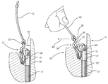
- FIG. 1 is a perspective view in partial cut away of a connector of the present invention disposed in interconnecting relation between a support platform and a supported object, which incorporate the MOLLE/PALS connecting system.
- FIG. 2A is a front view of the connector of the embodiment of FIG. 1 .
- FIG. 2B is a side view of the connector of the embodiment of FIGS. 1 and 2A .
- FIG. 2C is a rear view of the embodiment of FIGS. 1 , 2 A and 2 B.
- FIG. 3 is a perspective rear view in partial cutaway of a locking assembly associated with the connector of the embodiment of FIG. 1 .
- FIG. 4 is a front perspective view in partial cutaway of the locking assembly of the embodiment of FIG. 3 .
- FIG. 5 is an exploded view representing the operative positioning which accomplishes attachment or removal of the connector relative to both the supported object and support platform.
- FIG. 6 is a sectional view in partial cutaway of the connector represented in an operative position and the locking assembly disposed in a locking orientation.
- FIG. 7 is a sectional view in partial cutaway of the connector of the embodiment of FIG. 6 in an operative position and the locking assembly in a release orientation.
- FIG. 8 is a perspective, exploded view in partial phantom and cutaway representing the different operative positions of the connector of the embodiment of FIGS. 1 through 7 relative to the supported object and the support platform.
- FIG. 9 is a perspective view of another preferred embodiment of the present invention wherein a base of the connector includes a plurality of base members.
- the present invention is directed to a connector, generally indicated as 10 .
- the connector 10 is structured to removably and reliably connect a supported object 12 to a support platform 14 .
- the connector 10 is specifically, but not exclusively, for use in combination with a MOLLE/PALS attachment or connecting system.
- MOLLE/PALS system as well as attaching or connecting systems compatible therewith, are extensively used for removably securing military gear of various types to a vest, support belt or other garment type structure intended to be worn by or mounted on an individual.
- the individual as well as the complete structural details of the supporting garment or like structure are not shown.
- the PALS webbing structure as well as the MOLLE attachment system are cooperatively structured to include a plurality of webbing strips. More specifically and as clearly represented in FIG. 8 , the webbing strips on the military gear or supported object 12 are respectively indicated as 16 and 17 .
- the MOLLE system associated with the support platform 14 , also includes a plurality of elongated strips 18 , 19 , 20 etc. It is emphasized and commonly recognized that the MOLLE/PALS system includes each of the plurality of webbing strips 16 and 17 being attached to the surface of the supported object 12 in a manner which forms a plurality of immediately adjacent loops 16 ′, 17 ′.
- each of the webbing strips 16 and 17 on the supported object 12 are disposed in spaced relation to one another by elongated spaces 22 .
- each of a plurality of elongated spaces 24 is disposed between the adjacently disposed webbing strips 18 through 20 .
- the transverse dimension of each of the respective elongated spaces 22 and 24 are sufficient to respectively receive a correspondingly disposed webbing strip of the support platform 14 and the supported object 12 therein.
- operative positioning of the supported object 12 on the support platform 14 into the operative position represented in FIG. 1 calls for the webbing strips 16 and 17 of the supported object 12 being disposed within the elongated spaces 24 of the support platform 14 . Concurrently corresponding ones of the webbing strips 19 and 20 of the support platform 14 will be disposed within the corresponding spaces 22 of the supported object 12 .
- the operative positioning of the supported object 12 on the support platform 14 will also be defined by an axial alignment of the corresponding and immediately adjacent loops 18 ′, 16 ′, 19 ′, 17 ′, 20 ′ as also at least partially demonstrated in FIGS. 5 and 7 .
- This axial or linear alignment of correspondingly positioned loops will allow and facilitate the passage or “threading” of the connector 10 through the aligned an immediately adjacent loops 18 ′, 16 ′, 19 ′, 17 ,′, 20 ′ etc. and thereby serve to maintain a supported interconnection of the supported object 12 on the support platform 14 .
- the structural and operative features associated with the connector 10 include a base 30 comprising at least one elongated base member 31 formed from a rigid material and preferably, but not necessarily, being of a one piece construction.
- the length of the one base member 31 should be sufficient to pass or be threaded through immediately adjacent and axially aligned ones of the plurality of loops 18 ′, 16 ′, 19 ′, 17 ′, 20 ′, etc., as schematically represented by arrow 41 in FIG. 5 .
- a shorter length of the base 30 may be operable to establish the operative interconnection and attachment of the supported object 12 to the support platform 14 as represented in FIGS. 1 , 6 and 7 .
- the degree of rigidity of the one base member 31 may vary and demonstrate at least a minimal amount of flexibility, it should be sufficiently rigid to facilitate the threading or passage thereof through the aligned loops of the adjacently positioned webs 16 , 17 of the supported object 12 as well as the loops of webbing strips 18 through 20 of the support platform 14 .
- the connector 10 includes a locking assembly generally indicated as 32 disposed preferably, but not necessarily, at one end of the base 30 .
- the locking assembly 32 includes a retainer generally indicated as 34 and a gripping member generally indicated as 36 .
- the gripping member 36 is pivotally or otherwise appropriately movable relative to the retainer 34 and the base 30 .
- the locking assembly 32 and more specifically the gripping member 36 , is selectively positioned between a locking orientation, such as represented in FIG. 6 , and a release orientation such as represented in FIG. 7 .
- a locking orientation such as represented in FIG. 6
- a release orientation such as represented in FIG. 7
- at least a portion of the gripping member 36 is disposed in gripping engagement with the correspondingly disposed webbing strip 18 in FIG. 6 .
- the gripping member 36 includes at least one portion or segment such as projection 36 ′ which extends outwardly from the rear or corresponding surface of the gripping member 36 .
- the projection 36 ′ is disposed in gripping engagement and/or at least minimally penetrating relation to the outer surface or face of the next adjacent and correspondingly disposed webbing strip 18 and loop 18 ′.
- the gripping projection 36 ′ or other appropriate part of the gripping member 36 is disposed out of gripping engagement with the outer surface or face of the correspondingly disposed webbing strip 18 or loop 18 ′.
- the connector 10 can be easily removed from its threaded, interconnecting relation with immediately adjacent, aligned, alternating loops, 18 ′, 16 ′, 19 ′, 17 ′, 20 ′, etc. as indicated by directional arrow 41 in FIG. 5 .
- the connector when the connector is removed from its interconnecting relation with corresponding loops, the supported object 12 can be into or out of a confronting relation with the support platform 14 , as schematically indicated by directional arrow 41 ′ in FIG. 5 .
- the gripping member 36 may be selectively disposed in either the locking orientation of FIG. 6 or the release orientation of FIG. 7 , by exerting a positioning force on the gripping member 36 .
- another structural feature thereof includes an activating member 38 connected to the gripping member 36 .
- the activating member 38 is fixedly or integrally connected to the remainder of the gripping member 36 and may be disposed in an outwardly extending, readily accessible position as represented. Therefore, directional arrow 46 in FIG. 6 schematically represents a positioning force being exerted on the gripping member 36 via the activating member 38 which serves to dispose the gripping member 36 into a locking orientation.
- FIG. 7 represents the directional arrow 46 ′ being exerted on the gripping member 36 via the activating member 38 so as to dispose the gripping member 36 into the release orientation and out of the locking orientation of FIG. 6 .
- a pull member such as a pull cord 42 may be attached to the activating member 38 .
- the exertion of the positioning force 46 and/or 46 ′ on the gripping member 36 is significantly facilitated by actively accessing the gripping member 36 in order to position it by gripping and/or manipulating the pull member or pull cord 42 .
- the pull member 42 may be in the form of a flexible cord or any other appropriate structure which facilitates its gripping, pulling or other manipulation.
- retainer 34 and the gripping member 36 are cooperatively disposed, dimensioned and structured to removably maintain the gripping member 36 in either the locking orientation of FIG. 6 or the release orientation of FIG. 7 .
- Such cooperative structuring serves to maintain the gripping member in either of the locking orientation or release orientation, until the appropriate positioning force 46 or 46 ′ is applied to the gripping member 36 .
- retainer 34 includes at least one part or portion thereof 34 ′ which is disposed in interruptive relation to a gripping part or portion 37 of the gripping member 36 .
- gripping part 37 of the gripping member 36 moves past and in frictional but movable engagement with the part 34 ′ of the retainer 34 .
- the gripping part 37 thereof will come into abutting but movable and frictional sliding engagement with the part or portion 34 ′ of the retainer 34 .
- the dimensional tolerances between the gripping part 37 and the retainer part 34 ′ are such as to allow movement of the gripping part 37 beyond the retainer part 34 ′ and into and out of the locking or release orientations, when sufficient positioning force 46 and 46 ′ is exerted on the gripping member 36 .
- the movable, frictional engagement between the gripping part 37 and the retainer part 34 ′ can be said to at least provide a frictional, “snap-action” movement between the gripping member 36 and the retainer 34 as the positioning forces 46 and 46 ′ are alternatively exerted on the gripping member 36 .
- the configurations of the retainer part 34 ′ and the gripping part 37 as well as there cooperative dimensional tolerances are such as to removably maintain the gripping member 36 into either of the locking and/or release orientations once disposed therein.
- the disposition and configuration and overall structure of the retainer 34 specifically, but not exclusively, including the retainer part 34 ′ is such as to create a recess or channel 39 , as represented in FIG. 7 .
- the recess or channel 39 is disposed and configured to removably receive the gripping part 37 , when the gripping member 36 is in the gripping orientation of FIG. 6 .
- a sufficient positioning force 46 ′ must be exerted on the gripping member 36 to remove the gripping part 37 from the recess or channel 39 and beyond the retainer part 34 ′ as a movable, frictional, snap-action engagement occurs between the retainer part 34 ′ and the gripping part 37 . Therefore, the gripping member 36 will be at least partially maintained in the release orientation of FIG. 7 until a sufficient positioning force 46 is exerted thereon in order to overcome the frictional, sliding, snap-action between the gripping part 37 and the retainer part 34 ′.
- the connector 10 may be disposed such that the webbing strip engaged by the gripping member 36 may be either the webbing strip 16 and the loop 16 ′ or the webbing strip 18 and loop 18 ′.
- the connector 10 will be mounted on the support platform 14 , such that the gripping member 36 will engage and possibly at least minimally penetrate the outer surface or face of a next adjacent and corresponding loop 18 ′.
- the connector may also be operatively disposed to grip and engage the outer surface or face of the webbing strip 16 and corresponding loop 16 ′. Therefore, it should be apparent that the connector 10 may be disposed such that the gripping member 36 may engage either the support platform 14 or the supported object 12 to accomplish a supported attachment there between.
- the positioning of the connector 10 in either of the phantom positions of FIG. 8 indicates that the gripping member 36 will grip and possibly minimally penetrate the outer surface of the next closest, next adjacent, corresponding and/or upper most webbing strip and loop, 16 and 16 ′ or 18 and 18 ′.
- another embodiment of the present invention comprises a connector 10 ′ having a base 30 ′ comprising a plurality of at least two base members 31 ′.
- the base members 31 ′ include an elongated configuration and are formed of a sufficiently rigid material to facilitate the “threading” thereof through correspondingly aligned loops of the supported object 12 and support platform 14 .
- an elongated space 33 is disposed between inner portions of the base members 31 ′ and extends along a majority or substantially the entire lengths thereof, as indicated.
- the base members 31 may also be disposed in side-by-side, substantially coplanar relation to one another.
- the relative positions and structuring of the base members 31 ′, as well as the provision of the space 33 there between, facilitates there concurrent threading or passage through adjacent columns of loops 50 , 51 of the supported object and columns of loops 50 ′, 51 ′ of the support platform 14 , as schematically represented in FIG. 8 .
- the supported object 12 may be disposed in the operative position for connection to the support platform 14 , such as represented in FIGS. 1 , 6 and 7 .
- the two base members 31 ′ may concurrently pass or be threaded through the alternating, linearly aligned loops 18 ′, 16 ′, 19 ′, 17 ′ and 20 ′ of both the columns 50 and 51 of the support platform 14 and both columns 50 ′ and 51 ′ of the supported object 12 .
- the threading and removal of the base members 31 ′ will be the same as described above with reference to the threading and removal of the single base member 31 , as represented in FIG. 5 .
- the connector 10 ′ preferably includes at least one locking assembly 32 connected to both the base members 31 ′, such as at one end thereof.
- the locking assembly 32 connected to and considered a part of the connector 10 ′ will include the same structural and operative features as the locking assembly 32 represented and described in the embodiments of FIGS. 1-8 .
Abstract
Description
Claims (19)
Priority Applications (1)
| Application Number | Priority Date | Filing Date | Title |
|---|---|---|---|
| US13/398,473 US8713764B1 (en) | 2012-02-16 | 2012-02-16 | Connector structure |
Applications Claiming Priority (1)
| Application Number | Priority Date | Filing Date | Title |
|---|---|---|---|
| US13/398,473 US8713764B1 (en) | 2012-02-16 | 2012-02-16 | Connector structure |
Publications (1)
| Publication Number | Publication Date |
|---|---|
| US8713764B1 true US8713764B1 (en) | 2014-05-06 |
Family
ID=50552653
Family Applications (1)
| Application Number | Title | Priority Date | Filing Date |
|---|---|---|---|
| US13/398,473 Active 2032-03-26 US8713764B1 (en) | 2012-02-16 | 2012-02-16 | Connector structure |
Country Status (1)
| Country | Link |
|---|---|
| US (1) | US8713764B1 (en) |
Cited By (14)
| Publication number | Priority date | Publication date | Assignee | Title |
|---|---|---|---|---|
| US20140196203A1 (en) * | 2013-01-14 | 2014-07-17 | FirstSpear, LLC | Modular Armor Supplement Apparatus And System With Silent Fasteners And Adjustability |
| US20150327658A1 (en) * | 2013-09-25 | 2015-11-19 | S & S Precision, Llc | Gear track system |
| US9354023B1 (en) * | 2013-11-20 | 2016-05-31 | National Molding, Llc. | Holder for body mounted armor |
| US9504309B2 (en) | 2014-10-04 | 2016-11-29 | Douglas Ralph | Connector apparatus, system, and method of use |
| US9743719B2 (en) | 2013-10-02 | 2017-08-29 | National Molding, Llc. | Quick release buckle |
| US9752854B1 (en) | 2013-11-20 | 2017-09-05 | National Molding, Llc. | Holding for body mounted armor |
| USD801585S1 (en) * | 2016-01-15 | 2017-10-31 | Lance A. Doody | Strap claw |
| US20180368560A1 (en) * | 2017-06-26 | 2018-12-27 | Martin Cameron Evans | Attachment apparatus for modular load-carrying devices |
| US10299574B1 (en) * | 2017-11-06 | 2019-05-28 | Shin Fang Plastic Industrial Co., Ltd. | Plugging rod connector |
| US10605574B2 (en) | 2017-08-01 | 2020-03-31 | S&S Precision, Llc | Load bearing harness |
| US10619659B2 (en) | 2017-08-03 | 2020-04-14 | U.S. Farathane Corporation | Closure assembly with collapsible crush barbs configured within a recess cavity defining edge of a first piece for engagement by a projection of a second piece when press fit within the recess cavity in order to engage the pieces together |
| CN113397297A (en) * | 2020-03-17 | 2021-09-17 | 宇振塑料制品制造有限公司 | Clip for connecting backpack accessories |
| US11191345B2 (en) * | 2018-11-20 | 2021-12-07 | 5.11, Inc. | Auxiliary strap assembly |
| US20230072668A1 (en) * | 2020-02-18 | 2023-03-09 | Cirk-L Ab | Garment with adjustable attachment system |
Citations (8)
| Publication number | Priority date | Publication date | Assignee | Title |
|---|---|---|---|---|
| US4673070A (en) * | 1985-02-26 | 1987-06-16 | I.T.W. De France | Releasable assembly for connecting bag members |
| US7007352B1 (en) | 2003-09-26 | 2006-03-07 | Hill Michael R | Sliding reusable connector |
| US7080430B2 (en) | 2003-07-24 | 2006-07-25 | Best Made Designs, L.L.C. | Quick-mount interlocking attaching system |
| US20090117300A1 (en) | 2007-11-05 | 2009-05-07 | Jelis Incorporated | Modular attachment system and method |
| US20090277936A1 (en) | 2008-05-10 | 2009-11-12 | Prezine, Llc | Attachment mount and receiver system for removably attaching articles to garments |
| US20090307878A1 (en) | 2008-06-11 | 2009-12-17 | Kadas Jon F | Personal gear attachment system and apparatus |
| US20110121043A1 (en) | 2008-04-15 | 2011-05-26 | Kincaid Robert A | Adjustable, detachable accessory attachment system |
| US20110191933A1 (en) | 2008-10-24 | 2011-08-11 | Survitec Group Limited | Attachment systems |
-
2012
- 2012-02-16 US US13/398,473 patent/US8713764B1/en active Active
Patent Citations (9)
| Publication number | Priority date | Publication date | Assignee | Title |
|---|---|---|---|---|
| US4673070A (en) * | 1985-02-26 | 1987-06-16 | I.T.W. De France | Releasable assembly for connecting bag members |
| US7080430B2 (en) | 2003-07-24 | 2006-07-25 | Best Made Designs, L.L.C. | Quick-mount interlocking attaching system |
| US7251867B2 (en) | 2003-07-24 | 2007-08-07 | Best Made Designs, L.L.C. | Quick-mount interlocking attachment system |
| US7007352B1 (en) | 2003-09-26 | 2006-03-07 | Hill Michael R | Sliding reusable connector |
| US20090117300A1 (en) | 2007-11-05 | 2009-05-07 | Jelis Incorporated | Modular attachment system and method |
| US20110121043A1 (en) | 2008-04-15 | 2011-05-26 | Kincaid Robert A | Adjustable, detachable accessory attachment system |
| US20090277936A1 (en) | 2008-05-10 | 2009-11-12 | Prezine, Llc | Attachment mount and receiver system for removably attaching articles to garments |
| US20090307878A1 (en) | 2008-06-11 | 2009-12-17 | Kadas Jon F | Personal gear attachment system and apparatus |
| US20110191933A1 (en) | 2008-10-24 | 2011-08-11 | Survitec Group Limited | Attachment systems |
Cited By (23)
| Publication number | Priority date | Publication date | Assignee | Title |
|---|---|---|---|---|
| US11578948B2 (en) * | 2013-01-14 | 2023-02-14 | Firstspear Technology Group, Llc | Modular armor supplement apparatus and system with silent fasteners and adjustability |
| US20140196203A1 (en) * | 2013-01-14 | 2014-07-17 | FirstSpear, LLC | Modular Armor Supplement Apparatus And System With Silent Fasteners And Adjustability |
| US10281240B2 (en) * | 2013-01-14 | 2019-05-07 | FirstSpear, LLC | Modular armor supplement apparatus and system with silent fasteners and adjustability |
| US10238201B2 (en) * | 2013-09-25 | 2019-03-26 | S&S Precision, Llc | Gear track system |
| US20150327658A1 (en) * | 2013-09-25 | 2015-11-19 | S & S Precision, Llc | Gear track system |
| US9743719B2 (en) | 2013-10-02 | 2017-08-29 | National Molding, Llc. | Quick release buckle |
| US9354023B1 (en) * | 2013-11-20 | 2016-05-31 | National Molding, Llc. | Holder for body mounted armor |
| US9752854B1 (en) | 2013-11-20 | 2017-09-05 | National Molding, Llc. | Holding for body mounted armor |
| US9504309B2 (en) | 2014-10-04 | 2016-11-29 | Douglas Ralph | Connector apparatus, system, and method of use |
| USD801585S1 (en) * | 2016-01-15 | 2017-10-31 | Lance A. Doody | Strap claw |
| US20180368560A1 (en) * | 2017-06-26 | 2018-12-27 | Martin Cameron Evans | Attachment apparatus for modular load-carrying devices |
| US10555598B2 (en) * | 2017-06-26 | 2020-02-11 | Martin Cameron Evans | Attachment apparatus for modular load-carrying devices |
| US10605574B2 (en) | 2017-08-01 | 2020-03-31 | S&S Precision, Llc | Load bearing harness |
| US11041696B2 (en) | 2017-08-01 | 2021-06-22 | S&S Precision, Llc | Load bearing harness |
| US10619659B2 (en) | 2017-08-03 | 2020-04-14 | U.S. Farathane Corporation | Closure assembly with collapsible crush barbs configured within a recess cavity defining edge of a first piece for engagement by a projection of a second piece when press fit within the recess cavity in order to engage the pieces together |
| US10299574B1 (en) * | 2017-11-06 | 2019-05-28 | Shin Fang Plastic Industrial Co., Ltd. | Plugging rod connector |
| US11191345B2 (en) * | 2018-11-20 | 2021-12-07 | 5.11, Inc. | Auxiliary strap assembly |
| US11638474B2 (en) | 2018-11-20 | 2023-05-02 | 5.11, Inc. | Auxiliary strap assembly |
| US20230072668A1 (en) * | 2020-02-18 | 2023-03-09 | Cirk-L Ab | Garment with adjustable attachment system |
| EP3881712A1 (en) * | 2020-03-17 | 2021-09-22 | Woojin Plastic Co., Ltd | Clip for attachment accessories of backpack |
| US11330871B2 (en) | 2020-03-17 | 2022-05-17 | Woojin Plastic Co., Ltd. | Clip for attachment accessories of backpack |
| CN113397297B (en) * | 2020-03-17 | 2022-11-15 | 宇振塑料制品制造有限公司 | Clip for attaching backpack accessories |
| CN113397297A (en) * | 2020-03-17 | 2021-09-17 | 宇振塑料制品制造有限公司 | Clip for connecting backpack accessories |
Similar Documents
| Publication | Publication Date | Title |
|---|---|---|
| US8713764B1 (en) | Connector structure | |
| US7963427B2 (en) | Strap attachment system | |
| US20190000252A1 (en) | Garment assembly and release apparatus and method | |
| US10850940B2 (en) | Retracting device for mounting to a web strap | |
| EP3107628B1 (en) | Connector | |
| US9521897B2 (en) | Customizable MOLLE adapter panel | |
| US8732918B2 (en) | System and method for quick release | |
| US20120175390A1 (en) | Attachment mount system for removably securing articles to molle/pals-compliant garments | |
| US8191213B2 (en) | Quick release buckle assembly | |
| US20070289045A1 (en) | Garment and load attachment system | |
| US7644449B2 (en) | Load-bearing equipment | |
| US11399620B2 (en) | Connector | |
| US20120174341A1 (en) | Universal mounting platform and method for attaching same to garments | |
| WO1999030780A1 (en) | A rappel rope storage and deployment system | |
| US10595594B2 (en) | Rapid release device for wearable articles | |
| SE1250825A1 (en) | Carrying system with carrying straps | |
| WO2009005782A1 (en) | Secure, quick-release system for attaching a pouch to a larger bag | |
| US9504309B2 (en) | Connector apparatus, system, and method of use | |
| TWI689393B (en) | Sheath with attachment system | |
| EP3043667B1 (en) | Quickly releasable vest | |
| AU2022287494B2 (en) | Personal load bearing harness system for defense training or operational environments | |
| CN210374787U (en) | Bulletproof vest | |
| EP4289306A1 (en) | Quick release clip | |
| WO2024050140A2 (en) | Plate carrier system | |
| US20120234878A1 (en) | Quick-release attachment mechanism for load-bearing carriages |
Legal Events
| Date | Code | Title | Description |
|---|---|---|---|
| AS | Assignment |
Owner name: TEXAS CAPITAL BANK, NATIONAL ASSOCIATION, TEXAS Free format text: SECURITY AGREEMENT;ASSIGNOR:NATIONAL MOLDING, LLC;REEL/FRAME:029990/0001 Effective date: 20130311 |
|
| STCF | Information on status: patent grant |
Free format text: PATENTED CASE |
|
| AS | Assignment |
Owner name: NATIONAL MOLDING, LLC., UNITED STATES Free format text: ASSIGNMENT OF ASSIGNORS INTEREST;ASSIGNORS:RITTENHOUSE, JAMES;BEVILACQUA, MIGUEL;REEL/FRAME:034105/0832 Effective date: 20141104 |
|
| AS | Assignment |
Owner name: TEXAS CAPITAL BANK, NATIONAL ASSOCIATION, TEXAS Free format text: SECURITY INTEREST;ASSIGNOR:NATIONAL MOLDING, LLC;REEL/FRAME:039417/0697 Effective date: 20160715 |
|
| FEPP | Fee payment procedure |
Free format text: MAINTENANCE FEE REMINDER MAILED (ORIGINAL EVENT CODE: REM.) |
|
| FEPP | Fee payment procedure |
Free format text: SURCHARGE FOR LATE PAYMENT, SMALL ENTITY (ORIGINAL EVENT CODE: M2554) |
|
| MAFP | Maintenance fee payment |
Free format text: PAYMENT OF MAINTENANCE FEE, 4TH YR, SMALL ENTITY (ORIGINAL EVENT CODE: M2551) Year of fee payment: 4 |
|
| MAFP | Maintenance fee payment |
Free format text: PAYMENT OF MAINTENANCE FEE, 8TH YR, SMALL ENTITY (ORIGINAL EVENT CODE: M2552); ENTITY STATUS OF PATENT OWNER: SMALL ENTITY Year of fee payment: 8 |
|
| AS | Assignment |
Owner name: NATIONAL MOLDING, LLC, FLORIDA Free format text: RELEASE BY SECURED PARTY;ASSIGNOR:TEXAS CAPITAL BANK;REEL/FRAME:064740/0031 Effective date: 20230828 Owner name: TAGLICH PRIVATE EQUITY, LLC, NEW YORK Free format text: SECURITY INTEREST;ASSIGNORS:NATIONAL MOLDING, LLC;NATIONAL MOLDING - DURAFLEX, LLC;REEL/FRAME:064739/0644 Effective date: 20230828 |
|
| AS | Assignment |
Owner name: BYLINE BANK, ILLINOIS Free format text: SECURITY INTEREST;ASSIGNORS:NATIONAL MOLDING, LLC;NATIONAL MOLDING - DURAFLEX, LLC;REEL/FRAME:064758/0314 Effective date: 20230828 |
|
| AS | Assignment |
Owner name: SOUTHFIELD MEZZANINE CAPITAL LP, CONNECTICUT Free format text: SECURITY INTEREST;ASSIGNOR:NATIONAL MOLDING, LLC;REEL/FRAME:064793/0818 Effective date: 20230828 |