EP4102289A2 - Head-up-anzeigevorrichtung - Google Patents
Head-up-anzeigevorrichtung Download PDFInfo
- Publication number
- EP4102289A2 EP4102289A2 EP22170843.1A EP22170843A EP4102289A2 EP 4102289 A2 EP4102289 A2 EP 4102289A2 EP 22170843 A EP22170843 A EP 22170843A EP 4102289 A2 EP4102289 A2 EP 4102289A2
- Authority
- EP
- European Patent Office
- Prior art keywords
- image
- polarization
- region
- image beam
- display unit
- Prior art date
- Legal status (The legal status is an assumption and is not a legal conclusion. Google has not performed a legal analysis and makes no representation as to the accuracy of the status listed.)
- Pending
Links
- 230000010287 polarization Effects 0.000 claims abstract description 216
- 230000003287 optical effect Effects 0.000 claims abstract description 51
- 238000003384 imaging method Methods 0.000 claims description 27
- 230000008859 change Effects 0.000 claims description 4
- 230000005540 biological transmission Effects 0.000 claims description 3
- 230000008901 benefit Effects 0.000 description 9
- 230000006870 function Effects 0.000 description 3
- 230000003190 augmentative effect Effects 0.000 description 2
- 239000004973 liquid crystal related substance Substances 0.000 description 2
- 238000012986 modification Methods 0.000 description 2
- 230000004048 modification Effects 0.000 description 2
- 230000008878 coupling Effects 0.000 description 1
- 238000010168 coupling process Methods 0.000 description 1
- 238000005859 coupling reaction Methods 0.000 description 1
- 230000001419 dependent effect Effects 0.000 description 1
- 238000005516 engineering process Methods 0.000 description 1
- 239000000446 fuel Substances 0.000 description 1
- 239000011521 glass Substances 0.000 description 1
- 239000000463 material Substances 0.000 description 1
Images


Classifications
-
- G—PHYSICS
- G02—OPTICS
- G02B—OPTICAL ELEMENTS, SYSTEMS OR APPARATUS
- G02B27/00—Optical systems or apparatus not provided for by any of the groups G02B1/00 - G02B26/00, G02B30/00
- G02B27/01—Head-up displays
- G02B27/0101—Head-up displays characterised by optical features
-
- B—PERFORMING OPERATIONS; TRANSPORTING
- B60—VEHICLES IN GENERAL
- B60K—ARRANGEMENT OR MOUNTING OF PROPULSION UNITS OR OF TRANSMISSIONS IN VEHICLES; ARRANGEMENT OR MOUNTING OF PLURAL DIVERSE PRIME-MOVERS IN VEHICLES; AUXILIARY DRIVES FOR VEHICLES; INSTRUMENTATION OR DASHBOARDS FOR VEHICLES; ARRANGEMENTS IN CONNECTION WITH COOLING, AIR INTAKE, GAS EXHAUST OR FUEL SUPPLY OF PROPULSION UNITS IN VEHICLES
- B60K35/00—Instruments specially adapted for vehicles; Arrangement of instruments in or on vehicles
- B60K35/20—Output arrangements, i.e. from vehicle to user, associated with vehicle functions or specially adapted therefor
- B60K35/21—Output arrangements, i.e. from vehicle to user, associated with vehicle functions or specially adapted therefor using visual output, e.g. blinking lights or matrix displays
- B60K35/23—Head-up displays [HUD]
-
- G—PHYSICS
- G02—OPTICS
- G02B—OPTICAL ELEMENTS, SYSTEMS OR APPARATUS
- G02B27/00—Optical systems or apparatus not provided for by any of the groups G02B1/00 - G02B26/00, G02B30/00
- G02B27/0093—Optical systems or apparatus not provided for by any of the groups G02B1/00 - G02B26/00, G02B30/00 with means for monitoring data relating to the user, e.g. head-tracking, eye-tracking
-
- G—PHYSICS
- G02—OPTICS
- G02B—OPTICAL ELEMENTS, SYSTEMS OR APPARATUS
- G02B27/00—Optical systems or apparatus not provided for by any of the groups G02B1/00 - G02B26/00, G02B30/00
- G02B27/01—Head-up displays
- G02B27/0149—Head-up displays characterised by mechanical features
-
- G—PHYSICS
- G02—OPTICS
- G02B—OPTICAL ELEMENTS, SYSTEMS OR APPARATUS
- G02B27/00—Optical systems or apparatus not provided for by any of the groups G02B1/00 - G02B26/00, G02B30/00
- G02B27/01—Head-up displays
- G02B27/0179—Display position adjusting means not related to the information to be displayed
-
- G—PHYSICS
- G02—OPTICS
- G02B—OPTICAL ELEMENTS, SYSTEMS OR APPARATUS
- G02B27/00—Optical systems or apparatus not provided for by any of the groups G02B1/00 - G02B26/00, G02B30/00
- G02B27/28—Optical systems or apparatus not provided for by any of the groups G02B1/00 - G02B26/00, G02B30/00 for polarising
- G02B27/283—Optical systems or apparatus not provided for by any of the groups G02B1/00 - G02B26/00, G02B30/00 for polarising used for beam splitting or combining
-
- G—PHYSICS
- G02—OPTICS
- G02B—OPTICAL ELEMENTS, SYSTEMS OR APPARATUS
- G02B5/00—Optical elements other than lenses
- G02B5/30—Polarising elements
- G02B5/3083—Birefringent or phase retarding elements
-
- B—PERFORMING OPERATIONS; TRANSPORTING
- B60—VEHICLES IN GENERAL
- B60K—ARRANGEMENT OR MOUNTING OF PROPULSION UNITS OR OF TRANSMISSIONS IN VEHICLES; ARRANGEMENT OR MOUNTING OF PLURAL DIVERSE PRIME-MOVERS IN VEHICLES; AUXILIARY DRIVES FOR VEHICLES; INSTRUMENTATION OR DASHBOARDS FOR VEHICLES; ARRANGEMENTS IN CONNECTION WITH COOLING, AIR INTAKE, GAS EXHAUST OR FUEL SUPPLY OF PROPULSION UNITS IN VEHICLES
- B60K2360/00—Indexing scheme associated with groups B60K35/00 or B60K37/00 relating to details of instruments or dashboards
- B60K2360/20—Optical features of instruments
- B60K2360/23—Optical features of instruments using reflectors
-
- B—PERFORMING OPERATIONS; TRANSPORTING
- B60—VEHICLES IN GENERAL
- B60K—ARRANGEMENT OR MOUNTING OF PROPULSION UNITS OR OF TRANSMISSIONS IN VEHICLES; ARRANGEMENT OR MOUNTING OF PLURAL DIVERSE PRIME-MOVERS IN VEHICLES; AUXILIARY DRIVES FOR VEHICLES; INSTRUMENTATION OR DASHBOARDS FOR VEHICLES; ARRANGEMENTS IN CONNECTION WITH COOLING, AIR INTAKE, GAS EXHAUST OR FUEL SUPPLY OF PROPULSION UNITS IN VEHICLES
- B60K2360/00—Indexing scheme associated with groups B60K35/00 or B60K37/00 relating to details of instruments or dashboards
- B60K2360/20—Optical features of instruments
- B60K2360/25—Optical features of instruments using filters
-
- B—PERFORMING OPERATIONS; TRANSPORTING
- B60—VEHICLES IN GENERAL
- B60K—ARRANGEMENT OR MOUNTING OF PROPULSION UNITS OR OF TRANSMISSIONS IN VEHICLES; ARRANGEMENT OR MOUNTING OF PLURAL DIVERSE PRIME-MOVERS IN VEHICLES; AUXILIARY DRIVES FOR VEHICLES; INSTRUMENTATION OR DASHBOARDS FOR VEHICLES; ARRANGEMENTS IN CONNECTION WITH COOLING, AIR INTAKE, GAS EXHAUST OR FUEL SUPPLY OF PROPULSION UNITS IN VEHICLES
- B60K2360/00—Indexing scheme associated with groups B60K35/00 or B60K37/00 relating to details of instruments or dashboards
- B60K2360/20—Optical features of instruments
- B60K2360/33—Illumination features
- B60K2360/336—Light guides
-
- G—PHYSICS
- G02—OPTICS
- G02B—OPTICAL ELEMENTS, SYSTEMS OR APPARATUS
- G02B27/00—Optical systems or apparatus not provided for by any of the groups G02B1/00 - G02B26/00, G02B30/00
- G02B27/01—Head-up displays
- G02B27/0101—Head-up displays characterised by optical features
- G02B2027/0127—Head-up displays characterised by optical features comprising devices increasing the depth of field
-
- G—PHYSICS
- G02—OPTICS
- G02B—OPTICAL ELEMENTS, SYSTEMS OR APPARATUS
- G02B27/00—Optical systems or apparatus not provided for by any of the groups G02B1/00 - G02B26/00, G02B30/00
- G02B27/01—Head-up displays
- G02B27/0149—Head-up displays characterised by mechanical features
- G02B2027/015—Head-up displays characterised by mechanical features involving arrangement aiming to get less bulky devices
-
- G—PHYSICS
- G02—OPTICS
- G02B—OPTICAL ELEMENTS, SYSTEMS OR APPARATUS
- G02B27/00—Optical systems or apparatus not provided for by any of the groups G02B1/00 - G02B26/00, G02B30/00
- G02B27/01—Head-up displays
- G02B27/0149—Head-up displays characterised by mechanical features
- G02B2027/0152—Head-up displays characterised by mechanical features involving arrangement aiming to get lighter or better balanced devices
-
- G—PHYSICS
- G02—OPTICS
- G02B—OPTICAL ELEMENTS, SYSTEMS OR APPARATUS
- G02B27/00—Optical systems or apparatus not provided for by any of the groups G02B1/00 - G02B26/00, G02B30/00
- G02B27/01—Head-up displays
- G02B27/0179—Display position adjusting means not related to the information to be displayed
- G02B2027/0187—Display position adjusting means not related to the information to be displayed slaved to motion of at least a part of the body of the user, e.g. head, eye
Definitions
- the disclosure relates to a display device, and more particularly, to a head-up display device.
- An augmented reality head-up display device for a vehicle is generally designed to display images of two different contents.
- the content shown in one image may present fixed driving information, such as the vehicle speed, fuel level, mileage, and speed limit.
- the content shown in the other image presents driving information that relates to the road conditions, such as left and right turn signs, landmark information, and warning signs.
- the image that shows the fixed driving information is expected to be displayed at a closer depth from a driver, such as 2 meters, while the image that shows the driving information relating to the road conditions is displayed at a farther depth from the driver, such as 8 meters.
- the disclosure provides a head-up display device, which may reduce a system volume, reduce power consumption, and further reduce the cost.
- An embodiment of the disclosure provides a head-up display device, which is configured to project a first image beam and a second image beam onto a target element.
- the head-up display device includes a display unit, a polarization beam-splitting module, and an optical module.
- the display unit is configured to provide the first image beam having a first polarization direction and the second image beam having a second polarization direction.
- the polarization beam-splitting module receives the first image beam and the second image beam from the display unit, and transmits the first image beam and the second image beam to the optical module.
- the polarization beam-splitting module includes a polarization beam-splitting layer, a first reflection unit, and a second reflection unit.
- the polarization beam-splitting layer is configured to guide the second image beam to leave the polarization beam-splitting module, and guide the first image beam to the first reflection unit and the second reflection unit.
- the first reflection unit and the second reflection unit are not located on a transmission of the second image beam.
- the optical module includes a free-form mirror.
- the free-form mirror is configured to receive the first image beam and the second image beam from the polarization beam-splitting module.
- the first image beam and the second image beam are respectively reflected by the optical module to an outside of the head-up display device, and then transmitted to the target element, so as to form a first virtual image and a second virtual image.
- the polarization beam-splitting module an optical path length of the first image beam from the display unit to a position of the first virtual image formed by the first image beam is longer than an optical path length of the second image beam from the display unit to a position of the second virtual image formed by the second image beam.
- first polarization direction and the second polarization direction may be perpendicular to each other.
- the head-up display device may further comprise a sensor and a controller.#
- the senor may be configured to sense a position of an eye and generate a sensing signal.
- the controller may be electrically connected to the sensor and coupled to the optical module.
- the controller may receive the sensing signal from the sensor and may adjust a deflection angle of the free-form mirror corresponding to a change of the position of the eye, so that the first virtual image and the second virtual image are clearly presented.
- the first reflection unit may comprise a first mirror and a first quarter-wave plate.
- the second reflection unit may comprise a second mirror and a second quarter-wave plate.
- the first quarter-wave plate may be disposed between the first mirror and the polarization beam-splitting layer
- the second quarter-wave plate may be disposed between the second mirror and the polarization beam-splitting layer
- the polarization beam-splitting module may comprise a first region configured to enable the first image beam and the second image beam from the display unit to be incident and exited; and a second region adjacent to the first region, and configured to enable the first image beam to be incident and reflected a plurality of times before being exited to the first region.
- the polarization beam-splitting layer may be disposed between the first region and the second region, and may be configured to enable the first image beam having the first polarization direction to pass through and reflect the second image beam having the second polarization direction.
- the first reflection unit and the second reflection unit may be disposed beside the second region, and the first mirror and the second mirror may be perpendicular to each other.
- the first image beam from the display unit may sequentially pass through the first region and the polarization beam-splitting layer, and may then enter the second region, and the first image beam may pass through the first region to be transmitted to the optical module after sequentially passing through the first quarter-wave plate, being reflected by the first mirror, passing through the first quarter-wave plate, being reflected by the polarization beam-splitting layer, passing through the second quarter-wave plate, being reflected by the second mirror, passing through the second quarter-wave plate, and passing through the polarization beam-splitting layer; after the second image beam from the display unit enters the first region, the second image beam from the display unit may be reflected by the polarization beam-splitting layer to be transmitted to the optical module.
- the display unit may have a first effective imaging area and a second effective imaging area disposed adjacently to respectively generate the first image beam and the second image beam, and the first virtual image and the second virtual image formed outside the head-up display device present different image contents.
- a range of an orthographic projection of the first mirror on the display unit and the second effective imaging area of the display unit may not overlap with each other.
- the polarization beam-splitting module may comprise a first transparent body disposed in the first region and a second transparent body disposed in the second region, the polarization beam-splitting layer may be disposed on a surface of the second transparent body facing the first transparent body and located between the first transparent body and the second transparent body, and a contact area between the first transparent body and the polarization beam-splitting layer may be less than a total area of the polarization beam-splitting layer.
- a range of an orthographic projection of the first mirror on the display unit and the second effective imaging area of the display unit may overlap with each other.
- the polarization beam-splitting module may comprise a first transparent body disposed in the first region and a second transparent body disposed in the second region, the polarization beam-splitting layer may be disposed on a surface of the second transparent body facing the first transparent body or a surface of the first transparent body facing the second transparent body, and located between the first transparent body and the second transparent body, and a contact area between the first transparent body and the polarization beam-splitting layer may be equal to a total area of the polarization beam-splitting layer.
- the display unit may comprise an effective imaging area configured to generate the first image beam and the second image beam at different time intervals, and the first virtual image and the second virtual image formed outside the head-up display device may present different image contents.
- the head-up display device may further comprise a polarization switching device.
- the polarization switching device may be disposed between the display unit and the polarization beam-splitting module, at a first time interval, the first image beam emitted from the display unit may pass through the polarization switching device to have the first polarization direction, and at a second time interval, the second image beam emitted from the display unit may pass through the polarization switching device to have the second polarization direction.
- the polarization beam-splitting module may comprise a first transparent body disposed in the first region and a second transparent body disposed in the second region, and a contact area between the first transparent body and the second transparent body may be equal to an area of the polarization beam-splitting layer.
- the polarization beam-splitting module may comprise a first region and a second region.
- the first region may be disposed between the display unit and the second region
- the polarization beam-splitting layer may be disposed between the first region and the second region, and may be configured to reflect the first image beam having the first polarization direction and enable the second image beam having the second polarization direction to pass through.
- the first reflection unit and the second reflection unit may be respectively disposed beside the first region and the second region, and the first mirror and the second mirror are parallel to each other; the first image beam from the display unit may enter the first region and is reflected by the polarization beam-splitting layer, and the first image beam then may pass through the second region to be transmitted to the optical module after sequentially passing through the first quarter-wave plate, being reflected by the first mirror, passing through the first quarter-wave plate, passing through the polarization beam-splitting layer, entering the second region, passing through the second quarter-wave plate, being reflected by the second mirror, passing through the second quarter-wave plate, and passing through the polarization beam-splitting layer; after the second image beam from the display unit may enter the first region, the second image beam from the display unit may sequentially pass through the polarization beam-splitting layer and the second region to be transmitted to the optical module.
- the head-up display device is designed to enable a single display unit to generate the first image beam and the second image beam. Therefore, the architecture of the overall head-up display device has advantages such as smaller volume, lower power consumption, and lower cost.
- FIG. 1A is a schematic view of a head-up display device according to the first embodiment of the disclosure.
- FIG. 1B is a schematic view of two virtual images formed by the head-up display device according to the first embodiment of the disclosure.
- an embodiment of the disclosure provides a head-up display device 100, which is configured to project a first image beam B1 and a second image beam B2 onto a target element T.
- the head-up display device 100 is, for example, installed on a vehicle, such as a car.
- the target element T is, for example, a windshield of the car.
- the first image beam B1 and the second image beam B2 are reflected by the target element T to an eye E of a viewer (for example, a driver of the vehicle), so that the viewer may see a first virtual image VM1 and a second virtual image VM2 that are formed at different image distances and show different driving information in front of the target element T.
- a viewer for example, a driver of the vehicle
- the head-up display device 100 includes a display unit 110, a polarization beam-splitting module 120, and an optical module 130.
- the display unit 110 is configured to provide the first image beam B1 having a first polarization direction and the second image beam B2 having a second polarization direction.
- the first polarization direction and the second polarization direction are perpendicular to each other.
- the first polarization direction may be P polarization
- the second polarization direction may be S polarization
- the first polarization direction may be S polarization
- the second polarization direction may be P polarization.
- the disclosure is not limited thereto.
- the display unit 110 has a first effective imaging area E1 and a second effective imaging area E2 disposed adjacently.
- the display unit 110 may be a picture generation unit (PGU), which includes, for example, a transmissive liquid crystal panels or other light beam modulators.
- PGU picture generation unit
- the first effective imaging area E1 and the second effective imaging area E2 are arranged on the same plane of the display unit 110.
- the first effective imaging area E1 and the second effective imaging area E2 are configured to respectively generate the first image beam B1 and the second image beam B2, and the first virtual image VM1 and the second virtual image VM2 formed outside the head-up display device 100 present different image contents.
- the polarization beam-splitting module 120 receives the first image beam B1 and the second image beam B2 from the display unit 110, and transmits the first image beam B1 and the second image beam B2 to the optical module 130.
- the first effective imaging area E1 and the second effective imaging area E2 of the display unit 110 are, for example, respectively configured with a polarization selective film (not shown).
- the polarization selective film is disposed at a light exiting surface of the first effective imaging area E1, and the first image beam B1 passes through the polarization selective film to forms the beam having the first polarization direction.
- the polarization selective film is disposed at a light exiting surface of the second effective imaging area E2, and the second image beam B2 passes through the polarization selective film to form the beam having the second polarization direction.
- the polarization beam-splitting module 120 includes a first region R1 and a second regionR2.
- the first region R1 is configured to enable the first image beam B1 and the second image beam B2 from the display unit 110 to be incident, and enable the first image beam B1 and the second image beam B2 to be exited.
- the second region R2 is located adjacent to the first region R1, and is configured to enable the first image beam B1 to be incident and reflected multiple times before being exited to the first region R1.
- the polarization beam-splitting module 120 further includes a polarization beam-splitting layer 121, a first reflection unit 122, and a second reflection unit 123.
- the polarization beam-splitting layer 121 is disposed between the first region R1 and the second region R2, and is configured to enable the first image beam B1 having the first polarization direction to pass through and reflect the second image beam B2 having the second polarization direction. That is, the polarization beam-splitting layer 121 is configured to guide the second image beam B2 to leave the polarization beam-splitting module 120, and guide the first image beam B1 to the first reflection unit 122 and the second reflection unit 123.
- the polarization beam-splitting layer 121 for example, enables a P-polarized beam to pass through and reflects an S-polarized beam, or enables the S-polarized beam to pass through and reflects the P-polarized beam.
- the disclosure is not limited thereto.
- the first reflection unit 122 includes a first mirror 122-1 and a first quarter-wave plate 122-2.
- the second reflection unit 123 includes a second mirror 123-1 and a second quarter-wave plate 123-2.
- the first reflection unit 122 and the second reflection unit 123 are disposed beside the second region R2.
- the first quarter-wave plate 122-2 is disposed between the first mirror 122-1 and the polarization beam-splitting layer 121.
- the second quarter-wave plate 123-2 is disposed between the second mirror 123-1 and the polarization beam-splitting layer 121.
- the first mirror 122-1 and the second mirror 123-1 are arranged to be perpendicular to each other.
- the second region R2 is defined between the first reflection unit 122, the second reflection unit 123, and the polarization beam-splitting layer 121.
- the first image beam B1 having the first polarization direction from the first effective imaging area E1 of the display unit 110 sequentially passes through the first region R1 and the polarization beam-splitting layer 121, and then enters the second region R2.
- the first image beam B1 then passes through the first region R1 to be transmitted to the optical module 130 after sequentially passing through the first quarter-wave plate 122-2, being reflected by the first mirror 122-1, passing through the first quarter-wave plate 122-2, being reflected by the polarization beam-splitting layer 121, passing through the second quarter-wave plate 123-2, being reflected by the second mirror 123-1, passing through the second quarter-wave plate 123-2, and being reflected by the polarization beam-splitting layer 121.
- the first image beam B1 having the first polarization direction sequentially passes through the first quarter-wave plate 122-2, is reflected by the first mirror 122-1, and passes through the first quarter-wave plate 122-2.
- the first polarization direction of the first image beam B1 is converted into the second polarization direction after the first image beam B1 passes through the first quarter-wave plate 122-2 twice, and thus the first image beam B1 having the second polarization direction is reflected by the polarization beam-splitting layer 121.
- the first image beam B1 having the second polarization direction sequentially passes through the second quarter-wave plate 123-2, is reflected by the second mirror 123-1, and passes through the second quarter-wave plate 123-2.
- the second polarization direction of the first image beam B1 is converted into the first polarization direction after the first image beam B1 passes through the second quarter-wave plate 123-2 twice, and then the first image beam B1 having first polarization direction passes through the polarization beam-splitting layer 121.
- the second image beam B2 having the second polarization direction from the second effective area E2 of the display unit 110 enters the first region R1
- the second image beam B2 having the second polarization direction from the display unit 110 is reflected by the polarization beam-splitting layer 121 and is transmitted to the optical module 130.
- the first reflection unit 122 and the second reflection unit 123 are not located on a transmission path of the second image beam B2.
- a range of an orthographic projection of the first mirror 122-1 on the display unit 110 and the second effective imaging area E2 of the display unit 110 do not overlap with each other.
- the polarization beam-splitting module 120 includes a first transparent body 124 disposed in the first region R1 and a second transparent body 125 disposed in the second region R2.
- the polarization beam-splitting layer 121 is disposed between the first transparent body 124 and the second transparent body 125.
- a material of the transparent body is, for example, glass.
- the polarization beam-splitting layer 121 is, for example, disposed on a surface of the second transparent body 125 facing the first transparent body 124, and a contact area between the first transparent body 124 and the polarization beam-splitting layer 121 is less than a total area of the polarization beam-splitting layer 121.
- the optical module 130 includes a free-form mirror 132.
- the free-form mirror 132 is configured to receive the first image beam B1 and the second image beam B2 from the polarization beam-splitting module 120.
- the first image beam B1 and the second image beam B2 are respectively reflected by the optical module 130 to an outside of the head-up display device 100, and then is transmitted to the target element T, so as to form the first virtual image VM1 and the second virtual image VM2.
- an optical path length of the first image beam B1 from the display unit 110 to a position of the first virtual image VM1 formed by the first image beam B1 is longer than an optical path length of the second image beam B2 from the display unit 110 to a position of the second virtual image VM2 formed by the second image beam B2.
- the head-up display device 100 further includes a sensor 140 and a controller 150.
- the sensor 140 is configured to sense a position of the eye E and generate a sensing signal.
- the controller 150 includes, for example, a microcontroller unit (MCU), a central processing unit (CPU), a microprocessor, a digital signal processor (DSP), a programmable controller, a programmable logic device (PLD), other similar devices, or a combination of the devices.
- MCU microcontroller unit
- CPU central processing unit
- DSP digital signal processor
- PLD programmable logic device
- PLD programmable logic device
- each of functions of the controller 150 may be achieved as multiple program codes.
- the program codes are stored in a memory, and executed by the controller 150.
- each of the functions of the controller 150 may be achieved as one or more circuits.
- the disclosure does not limit the use of software or hardware to achieve the functions of the controller 150.
- the controller 150 is electrically connected to the sensor 140, and coupled to the optical module 130.
- the optical module 130 includes a driver (not shown) electrically connected to the free-form mirror 132 to drive the deflection of the free-form mirror 132.
- the controller 150 receives the sensing signal from the sensor 140, and controls the driver to adjust a deflection angle of the free-form mirror 132 corresponding to a change of the position of the eye E of the user (the driver), so that the first virtual image VM1 and the second virtual image VM2 are clearly presented.
- the head-up display device 100 is designed to enable the display unit 110 to generate the first image beam B1 having the first polarization direction and the second image beam B2 having the second polarization direction at the same time.
- the head-up display device 100 is designed as follows. The first image beam B1 is reflected three times by the polarization beam-splitting module 120, and the second image beam B2 is reflected once by the polarization beam-splitting module 120, so that the optical path length of the first image beam B1 from the display unit 110 to the position of the first virtual image VM1 is longer than the optical path length of the second image beam B2 from the display unit 110 to the position of the second virtual image VM2. Therefore, an architecture of the overall head-up display device 100 has advantages such as smaller volume, lower power consumption, and lower cost.
- FIG. 2 is a schematic view of a polarization beam-splitting module in a head-up display device according to the second embodiment of the disclosure.
- a polarization beam-splitting module 120A of FIG. 2 is similar to the polarization beam-splitting module 120 of FIG. 1A , and the main difference is as follows.
- the range of the orthographic projection of the first mirror 122-1 on the display unit 110 and the second effective imaging area E2 of the display unit 110 overlap with each other.
- the polarization beam-splitting module 120A includes a first transparent body 124A disposed in the first region Rland a second transparent body 125 disposed in the second region R2.
- the polarization beam-splitting layer 121 is disposed on the surface of the second transparent body 125 facing the first transparent body 124A or a surface of the first transparent body 124A facing the second transparent body 125, and is located between the first transparent body 124A and the second transparent body 125.
- a contact area between the first transparent body 124A and the polarization beam-splitting layer 121 is equal to the total area of the polarization beam-splitting layer 121.
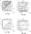
- FIG. 3A is a schematic view of an optical path of a first image beam in a polarization beam-splitting module of a head-up display device at a first time interval according to the third embodiment of the disclosure.
- FIG. 3B is a schematic view of the optical path of a second image beam of the polarization beam-splitting module in the head-up display device at a second time interval according to the third embodiment of the disclosure.
- a polarization beam-splitting module 120B of FIGs. 3A or 3B is similar to the polarization beam-splitting module 120 of FIG. 1A , and a relative position of a virtual image formed by the polarization beam-splitting module 120B of FIG.
- the display unit 110 includes an effective imaging area E3.
- the effective imaging area E3 is configured to generate the first image beam B1 and the second image beam B2 at different time intervals, and the first virtual image VM1 and the second virtual image VM2 formed outside the head-up display device present different image contents (as shown in FIG. 1B ).
- the head-up display device further includes a polarization switching device 112.
- the polarization switching device 112 is disposed between the display unit 110 and the polarization beam-splitting module 120B to change the polarization direction of the image beam passing therethrough in different time intervals.
- the polarization switching device 112 is, for example, a polarization rotator such as a liquid crystal panel.
- the first image beam B1 emitted from the effective imaging area E3 of the display unit 110 passes through the polarization switching device 112 to have the first polarization direction.
- the second image beam B2 emitted from the effective imaging area E3 of the display unit 110 passes through the polarization switching device 112 to have the second polarization direction.
- the polarization beam-splitting module 120B includes the first transparent body 124A disposed in the first region R1 and the second transparent body 125 disposed in the second region R2.
- the polarization beam-splitting layer 121 is disposed between the second transparent body 125 and the first transparent body 124A, and the contact area between the first transparent body 124A and the polarization beam-splitting layer 121 is equal to the total area of the polarization beam-splitting layer 121.
- FIG. 4A is a schematic view of an optical path of a first image beam in a polarization beam-splitting module of a head-up display device at a first time interval according to the fourth embodiment of the disclosure.
- FIG. 4B is a schematic view of the optical path of a second image beam in the polarization beam-splitting module of the head-up display device at a second time interval according to the fourth embodiment of the disclosure.
- a polarization beam-splitting module 120C of FIGs. 4A or 4B is similar to the polarization beam-splitting module 120 of FIG. 1A , and a relative position of a virtual image formed by the polarization beam-splitting module 120C of FIG.
- FIG. 4A or FIG. 4B is also similar to that of FIG. 1B .
- the main difference is as follows.
- the head-up display device is designed as follows. The first image beam B1 is reflected three times by the polarization beam-splitting module 120C, but the second image beam B2 directly passes through the polarization beam-splitting module 120C.
- the polarization beam-splitting module 120C includes the first region R1 and the second region R2.
- the first region R1 is disposed between the display unit 110 and the second region R2.
- the polarization beam-splitting layer 121 is disposed between the first region R1 and the second region R2, and is configured to reflect the first image beam B1 having the first polarization direction and enable the second image beam B2 having the second polarization direction to pass through.
- a first reflection unit 122C and a second reflection unit 123C are respectively disposed beside the first region R1 and the second region R2, and the first reflection unit 122C and the second reflection unit 123C are respectively located at two opposite sides of the polarization beam-splitting module 120C.
- a first mirror 122-1' and a second mirror 123-1' are arranged to be parallel to each other.
- the first image beam B1 from the display unit 110 enters the first region R1, and is reflected by the polarization beam-splitting layer 121.
- the first image beam B1 After sequentially passing through a first quarter-wave plate 122-2', being reflected by the first mirror 122-1', passing through the first quarter-wave plate 122-2', passing through the polarization beam-splitting layer 121, entering the second region R2, passing through a second quarter-wave plate 123-2', being reflected by the second mirror 123-1', passing through the second quarter-wave plate 123-2', and being reflected by the polarization beam-splitting layer 121, the first image beam B1 then passes through the second region R2 to be transmitted to the optical module 130.
- the first image beam B1 having the first polarization direction sequentially passes through the first quarter-wave plate 122-2', is reflected by the first mirror 122-1', and passes through the first quarter-wave plate 122-2'.
- the first polarization direction of the first image beam B1 is converted into the second polarization direction after the first image beam B1 passes through the first quarter-wave plate 122-2' twice, and thus the first image beam B1 having the second polarization direction passes through the polarization beam-splitting layer 121. Then, the first image beam B1 having the second polarization direction sequentially passes through the second quarter-wave plate 123-2', is reflected by the second mirror 123-1', and passes through the second quarter-wave plate 123-2'.
- the second polarization direction of the first image beam B1 is converted into the first polarization direction after the first image beam B1 passes through the second quarter-wave plate 123-2' twice, and then the first image beam B1 having the first polarization direction is reflected by the polarization beam-splitting layer 121.
- the second image beam B2 having the second polarization direction from the display unit 110 sequentially passes through the polarization beam-splitting layer 121 and the second region R2 to be transmitted to the optical module 130.
- the head-up display device is designed to enable the display unit to generate the first image beam and the second image beam, and enable the optical path length of the first image beam from the display unit to the position of the first virtual image to be longer than the optical path length of the second image beam from the display unit to the position of the second virtual image through a design of the polarization beam splitting module. Therefore, the architecture of the overall head-up display device has the advantages such as smaller volume, lower power consumption, and lower cost.
- the term "the invention”, “the present invention” or the like does not necessarily limit the claim scope to a specific embodiment, and the reference to particularly preferred exemplary embodiments of the invention does not imply a limitation on the invention, and no such limitation is to be inferred.
- the invention is limited only by the spirit and scope of the appended claims.
- the abstract of the disclosure is provided to comply with the rules requiring an abstract, which will allow a searcher to quickly ascertain the subject matter of the technical disclosure of any patent issued from this disclosure. It is submitted with the understanding that it will not be used to interpret or limit the scope or meaning of the claims. Any advantages and benefits described may not apply to all embodiments of the invention.
Landscapes
- Physics & Mathematics (AREA)
- General Physics & Mathematics (AREA)
- Optics & Photonics (AREA)
- Engineering & Computer Science (AREA)
- Chemical & Material Sciences (AREA)
- Combustion & Propulsion (AREA)
- Transportation (AREA)
- Mechanical Engineering (AREA)
- Instrument Panels (AREA)
Applications Claiming Priority (2)
| Application Number | Priority Date | Filing Date | Title |
|---|---|---|---|
| US202163191337P | 2021-05-21 | 2021-05-21 | |
| CN202110788125.5A CN115373145A (zh) | 2021-05-21 | 2021-07-13 | 抬头显示装置 |
Publications (2)
| Publication Number | Publication Date |
|---|---|
| EP4102289A2 true EP4102289A2 (de) | 2022-12-14 |
| EP4102289A3 EP4102289A3 (de) | 2023-03-01 |
Family
ID=81448551
Family Applications (1)
| Application Number | Title | Priority Date | Filing Date |
|---|---|---|---|
| EP22170843.1A Pending EP4102289A3 (de) | 2021-05-21 | 2022-04-29 | Head-up-anzeigevorrichtung |
Country Status (4)
| Country | Link |
|---|---|
| US (1) | US20220373798A1 (de) |
| EP (1) | EP4102289A3 (de) |
| JP (1) | JP2022179358A (de) |
| KR (1) | KR20220157903A (de) |
Family Cites Families (4)
| Publication number | Priority date | Publication date | Assignee | Title |
|---|---|---|---|---|
| JP2009292409A (ja) * | 2008-06-09 | 2009-12-17 | Yazaki Corp | ヘッドアップディスプレイ装置 |
| JP6271006B2 (ja) * | 2014-06-13 | 2018-01-31 | 三菱電機株式会社 | 虚像表示装置 |
| WO2017170702A1 (ja) * | 2016-03-30 | 2017-10-05 | 三菱電機株式会社 | ヘッドアップディスプレイ装置 |
| EP3958037A4 (de) * | 2019-03-21 | 2022-11-02 | BOE Technology Group Co., Ltd. | Anzeigesystem mit integrierter bildgebung |
-
2022
- 2022-04-20 JP JP2022069315A patent/JP2022179358A/ja active Pending
- 2022-04-21 US US17/725,552 patent/US20220373798A1/en active Pending
- 2022-04-29 EP EP22170843.1A patent/EP4102289A3/de active Pending
- 2022-05-19 KR KR1020220061435A patent/KR20220157903A/ko unknown
Also Published As
| Publication number | Publication date |
|---|---|
| US20220373798A1 (en) | 2022-11-24 |
| JP2022179358A (ja) | 2022-12-02 |
| EP4102289A3 (de) | 2023-03-01 |
| KR20220157903A (ko) | 2022-11-29 |
Similar Documents
| Publication | Publication Date | Title |
|---|---|---|
| EP2755074B1 (de) | Anzeigevorrichtung für ein fahrzeug | |
| US10578866B2 (en) | Head up display device with a polarization separation element | |
| WO2015159523A1 (ja) | ヘッドアップディスプレイ、およびヘッドアップディスプレイを搭載した移動体 | |
| TWI582465B (zh) | 抬頭顯示系統 | |
| JP2002356118A (ja) | 車両用表示装置 | |
| JP2006208606A (ja) | 車載用表示装置 | |
| US20140253820A1 (en) | Liquid crystal device, electronic device and projector | |
| JP2010139938A (ja) | タッチパネル及びタッチパネル付き液晶表示装置 | |
| JPH06305342A (ja) | 車両用表示装置 | |
| US11029556B2 (en) | Display device | |
| JP2007186017A (ja) | 車両用表示装置 | |
| EP4102289A2 (de) | Head-up-anzeigevorrichtung | |
| CN114764195A (zh) | 一种hud系统及车辆 | |
| EP3605194B1 (de) | Virtuelle bildanzeigevorrichtung | |
| US20220244533A1 (en) | Polarization rotator for head-up display | |
| CN111295615A (zh) | 图像显示系统 | |
| JP6354771B2 (ja) | 表示装置 | |
| CN117348320A (zh) | 投影装置、交通工具和显示设备 | |
| TWI782622B (zh) | 抬頭顯示裝置 | |
| US20220373813A1 (en) | Head-up display device | |
| CN112946910A (zh) | 一种具有裸眼3d显示效果的仪表 | |
| EP4163701A1 (de) | Bilderzeugungseinheit und head-up-anzeige | |
| JPH10239629A (ja) | 表示装置 | |
| US20230415576A1 (en) | Head-up display and means of transportation comprising a head-up display | |
| US20080316430A1 (en) | Projection apparatus |
Legal Events
| Date | Code | Title | Description |
|---|---|---|---|
| PUAI | Public reference made under article 153(3) epc to a published international application that has entered the european phase |
Free format text: ORIGINAL CODE: 0009012 |
|
| STAA | Information on the status of an ep patent application or granted ep patent |
Free format text: STATUS: THE APPLICATION HAS BEEN PUBLISHED |
|
| AK | Designated contracting states |
Kind code of ref document: A2 Designated state(s): AL AT BE BG CH CY CZ DE DK EE ES FI FR GB GR HR HU IE IS IT LI LT LU LV MC MK MT NL NO PL PT RO RS SE SI SK SM TR |
|
| PUAL | Search report despatched |
Free format text: ORIGINAL CODE: 0009013 |
|
| AK | Designated contracting states |
Kind code of ref document: A3 Designated state(s): AL AT BE BG CH CY CZ DE DK EE ES FI FR GB GR HR HU IE IS IT LI LT LU LV MC MK MT NL NO PL PT RO RS SE SI SK SM TR |
|
| RIC1 | Information provided on ipc code assigned before grant |
Ipc: G02B 27/28 20060101ALI20230120BHEP Ipc: G02B 27/01 20060101AFI20230120BHEP |
|
| STAA | Information on the status of an ep patent application or granted ep patent |
Free format text: STATUS: REQUEST FOR EXAMINATION WAS MADE |
|
| 17P | Request for examination filed |
Effective date: 20230829 |
|
| RBV | Designated contracting states (corrected) |
Designated state(s): AL AT BE BG CH CY CZ DE DK EE ES FI FR GB GR HR HU IE IS IT LI LT LU LV MC MK MT NL NO PL PT RO RS SE SI SK SM TR |