EP4102130A1 - Lighting apparatus for vehicle and control method thereof - Google Patents
Lighting apparatus for vehicle and control method thereof Download PDFInfo
- Publication number
- EP4102130A1 EP4102130A1 EP22167085.4A EP22167085A EP4102130A1 EP 4102130 A1 EP4102130 A1 EP 4102130A1 EP 22167085 A EP22167085 A EP 22167085A EP 4102130 A1 EP4102130 A1 EP 4102130A1
- Authority
- EP
- European Patent Office
- Prior art keywords
- vehicle
- opening
- light emitting
- unit
- flap
- Prior art date
- Legal status (The legal status is an assumption and is not a legal conclusion. Google has not performed a legal analysis and makes no representation as to the accuracy of the status listed.)
- Granted
Links
Images








Classifications
-
- F—MECHANICAL ENGINEERING; LIGHTING; HEATING; WEAPONS; BLASTING
- F21—LIGHTING
- F21S—NON-PORTABLE LIGHTING DEVICES; SYSTEMS THEREOF; VEHICLE LIGHTING DEVICES SPECIALLY ADAPTED FOR VEHICLE EXTERIORS
- F21S41/00—Illuminating devices specially adapted for vehicle exteriors, e.g. headlamps
- F21S41/60—Illuminating devices specially adapted for vehicle exteriors, e.g. headlamps characterised by a variable light distribution
- F21S41/68—Illuminating devices specially adapted for vehicle exteriors, e.g. headlamps characterised by a variable light distribution by acting on screens
- F21S41/683—Illuminating devices specially adapted for vehicle exteriors, e.g. headlamps characterised by a variable light distribution by acting on screens by moving screens
- F21S41/689—Flaps, i.e. screens pivoting around one of their edges
-
- B—PERFORMING OPERATIONS; TRANSPORTING
- B60—VEHICLES IN GENERAL
- B60Q—ARRANGEMENT OF SIGNALLING OR LIGHTING DEVICES, THE MOUNTING OR SUPPORTING THEREOF OR CIRCUITS THEREFOR, FOR VEHICLES IN GENERAL
- B60Q1/00—Arrangement of optical signalling or lighting devices, the mounting or supporting thereof or circuits therefor
- B60Q1/26—Arrangement of optical signalling or lighting devices, the mounting or supporting thereof or circuits therefor the devices being primarily intended to indicate the vehicle, or parts thereof, or to give signals, to other traffic
-
- B—PERFORMING OPERATIONS; TRANSPORTING
- B60—VEHICLES IN GENERAL
- B60Q—ARRANGEMENT OF SIGNALLING OR LIGHTING DEVICES, THE MOUNTING OR SUPPORTING THEREOF OR CIRCUITS THEREFOR, FOR VEHICLES IN GENERAL
- B60Q1/00—Arrangement of optical signalling or lighting devices, the mounting or supporting thereof or circuits therefor
- B60Q1/0017—Devices integrating an element dedicated to another function
- B60Q1/0023—Devices integrating an element dedicated to another function the element being a sensor, e.g. distance sensor, camera
-
- B—PERFORMING OPERATIONS; TRANSPORTING
- B60—VEHICLES IN GENERAL
- B60Q—ARRANGEMENT OF SIGNALLING OR LIGHTING DEVICES, THE MOUNTING OR SUPPORTING THEREOF OR CIRCUITS THEREFOR, FOR VEHICLES IN GENERAL
- B60Q1/00—Arrangement of optical signalling or lighting devices, the mounting or supporting thereof or circuits therefor
- B60Q1/02—Arrangement of optical signalling or lighting devices, the mounting or supporting thereof or circuits therefor the devices being primarily intended to illuminate the way ahead or to illuminate other areas of way or environments
- B60Q1/04—Arrangement of optical signalling or lighting devices, the mounting or supporting thereof or circuits therefor the devices being primarily intended to illuminate the way ahead or to illuminate other areas of way or environments the devices being headlights
- B60Q1/06—Arrangement of optical signalling or lighting devices, the mounting or supporting thereof or circuits therefor the devices being primarily intended to illuminate the way ahead or to illuminate other areas of way or environments the devices being headlights adjustable, e.g. remotely-controlled from inside vehicle
- B60Q1/068—Arrangement of optical signalling or lighting devices, the mounting or supporting thereof or circuits therefor the devices being primarily intended to illuminate the way ahead or to illuminate other areas of way or environments the devices being headlights adjustable, e.g. remotely-controlled from inside vehicle by mechanical means
-
- B—PERFORMING OPERATIONS; TRANSPORTING
- B60—VEHICLES IN GENERAL
- B60Q—ARRANGEMENT OF SIGNALLING OR LIGHTING DEVICES, THE MOUNTING OR SUPPORTING THEREOF OR CIRCUITS THEREFOR, FOR VEHICLES IN GENERAL
- B60Q1/00—Arrangement of optical signalling or lighting devices, the mounting or supporting thereof or circuits therefor
- B60Q1/0029—Spatial arrangement
- B60Q1/0041—Spatial arrangement of several lamps in relation to each other
-
- B—PERFORMING OPERATIONS; TRANSPORTING
- B60—VEHICLES IN GENERAL
- B60Q—ARRANGEMENT OF SIGNALLING OR LIGHTING DEVICES, THE MOUNTING OR SUPPORTING THEREOF OR CIRCUITS THEREFOR, FOR VEHICLES IN GENERAL
- B60Q1/00—Arrangement of optical signalling or lighting devices, the mounting or supporting thereof or circuits therefor
- B60Q1/02—Arrangement of optical signalling or lighting devices, the mounting or supporting thereof or circuits therefor the devices being primarily intended to illuminate the way ahead or to illuminate other areas of way or environments
- B60Q1/04—Arrangement of optical signalling or lighting devices, the mounting or supporting thereof or circuits therefor the devices being primarily intended to illuminate the way ahead or to illuminate other areas of way or environments the devices being headlights
- B60Q1/06—Arrangement of optical signalling or lighting devices, the mounting or supporting thereof or circuits therefor the devices being primarily intended to illuminate the way ahead or to illuminate other areas of way or environments the devices being headlights adjustable, e.g. remotely-controlled from inside vehicle
- B60Q1/08—Arrangement of optical signalling or lighting devices, the mounting or supporting thereof or circuits therefor the devices being primarily intended to illuminate the way ahead or to illuminate other areas of way or environments the devices being headlights adjustable, e.g. remotely-controlled from inside vehicle automatically
- B60Q1/085—Arrangement of optical signalling or lighting devices, the mounting or supporting thereof or circuits therefor the devices being primarily intended to illuminate the way ahead or to illuminate other areas of way or environments the devices being headlights adjustable, e.g. remotely-controlled from inside vehicle automatically due to special conditions, e.g. adverse weather, type of road, badly illuminated road signs or potential dangers
-
- B—PERFORMING OPERATIONS; TRANSPORTING
- B60—VEHICLES IN GENERAL
- B60Q—ARRANGEMENT OF SIGNALLING OR LIGHTING DEVICES, THE MOUNTING OR SUPPORTING THEREOF OR CIRCUITS THEREFOR, FOR VEHICLES IN GENERAL
- B60Q1/00—Arrangement of optical signalling or lighting devices, the mounting or supporting thereof or circuits therefor
- B60Q1/02—Arrangement of optical signalling or lighting devices, the mounting or supporting thereof or circuits therefor the devices being primarily intended to illuminate the way ahead or to illuminate other areas of way or environments
- B60Q1/04—Arrangement of optical signalling or lighting devices, the mounting or supporting thereof or circuits therefor the devices being primarily intended to illuminate the way ahead or to illuminate other areas of way or environments the devices being headlights
- B60Q1/14—Arrangement of optical signalling or lighting devices, the mounting or supporting thereof or circuits therefor the devices being primarily intended to illuminate the way ahead or to illuminate other areas of way or environments the devices being headlights having dimming means
- B60Q1/1438—Actuating means for dimming masks or screens
-
- B—PERFORMING OPERATIONS; TRANSPORTING
- B60—VEHICLES IN GENERAL
- B60Q—ARRANGEMENT OF SIGNALLING OR LIGHTING DEVICES, THE MOUNTING OR SUPPORTING THEREOF OR CIRCUITS THEREFOR, FOR VEHICLES IN GENERAL
- B60Q1/00—Arrangement of optical signalling or lighting devices, the mounting or supporting thereof or circuits therefor
- B60Q1/26—Arrangement of optical signalling or lighting devices, the mounting or supporting thereof or circuits therefor the devices being primarily intended to indicate the vehicle, or parts thereof, or to give signals, to other traffic
- B60Q1/34—Arrangement of optical signalling or lighting devices, the mounting or supporting thereof or circuits therefor the devices being primarily intended to indicate the vehicle, or parts thereof, or to give signals, to other traffic for indicating change of drive direction
-
- B—PERFORMING OPERATIONS; TRANSPORTING
- B60—VEHICLES IN GENERAL
- B60Q—ARRANGEMENT OF SIGNALLING OR LIGHTING DEVICES, THE MOUNTING OR SUPPORTING THEREOF OR CIRCUITS THEREFOR, FOR VEHICLES IN GENERAL
- B60Q1/00—Arrangement of optical signalling or lighting devices, the mounting or supporting thereof or circuits therefor
- B60Q1/26—Arrangement of optical signalling or lighting devices, the mounting or supporting thereof or circuits therefor the devices being primarily intended to indicate the vehicle, or parts thereof, or to give signals, to other traffic
- B60Q1/34—Arrangement of optical signalling or lighting devices, the mounting or supporting thereof or circuits therefor the devices being primarily intended to indicate the vehicle, or parts thereof, or to give signals, to other traffic for indicating change of drive direction
- B60Q1/38—Arrangement of optical signalling or lighting devices, the mounting or supporting thereof or circuits therefor the devices being primarily intended to indicate the vehicle, or parts thereof, or to give signals, to other traffic for indicating change of drive direction using immovably-mounted light sources, e.g. fixed flashing lamps
- B60Q1/381—Arrangement of optical signalling or lighting devices, the mounting or supporting thereof or circuits therefor the devices being primarily intended to indicate the vehicle, or parts thereof, or to give signals, to other traffic for indicating change of drive direction using immovably-mounted light sources, e.g. fixed flashing lamps with several light sources activated in sequence, e.g. to create a sweep effect
-
- B—PERFORMING OPERATIONS; TRANSPORTING
- B60—VEHICLES IN GENERAL
- B60Q—ARRANGEMENT OF SIGNALLING OR LIGHTING DEVICES, THE MOUNTING OR SUPPORTING THEREOF OR CIRCUITS THEREFOR, FOR VEHICLES IN GENERAL
- B60Q1/00—Arrangement of optical signalling or lighting devices, the mounting or supporting thereof or circuits therefor
- B60Q1/26—Arrangement of optical signalling or lighting devices, the mounting or supporting thereof or circuits therefor the devices being primarily intended to indicate the vehicle, or parts thereof, or to give signals, to other traffic
- B60Q1/50—Arrangement of optical signalling or lighting devices, the mounting or supporting thereof or circuits therefor the devices being primarily intended to indicate the vehicle, or parts thereof, or to give signals, to other traffic for indicating other intentions or conditions, e.g. request for waiting or overtaking
-
- B—PERFORMING OPERATIONS; TRANSPORTING
- B60—VEHICLES IN GENERAL
- B60W—CONJOINT CONTROL OF VEHICLE SUB-UNITS OF DIFFERENT TYPE OR DIFFERENT FUNCTION; CONTROL SYSTEMS SPECIALLY ADAPTED FOR HYBRID VEHICLES; ROAD VEHICLE DRIVE CONTROL SYSTEMS FOR PURPOSES NOT RELATED TO THE CONTROL OF A PARTICULAR SUB-UNIT
- B60W50/00—Details of control systems for road vehicle drive control not related to the control of a particular sub-unit, e.g. process diagnostic or vehicle driver interfaces
- B60W50/08—Interaction between the driver and the control system
- B60W50/14—Means for informing the driver, warning the driver or prompting a driver intervention
-
- F—MECHANICAL ENGINEERING; LIGHTING; HEATING; WEAPONS; BLASTING
- F21—LIGHTING
- F21S—NON-PORTABLE LIGHTING DEVICES; SYSTEMS THEREOF; VEHICLE LIGHTING DEVICES SPECIALLY ADAPTED FOR VEHICLE EXTERIORS
- F21S41/00—Illuminating devices specially adapted for vehicle exteriors, e.g. headlamps
- F21S41/10—Illuminating devices specially adapted for vehicle exteriors, e.g. headlamps characterised by the light source
- F21S41/14—Illuminating devices specially adapted for vehicle exteriors, e.g. headlamps characterised by the light source characterised by the type of light source
- F21S41/141—Light emitting diodes [LED]
- F21S41/151—Light emitting diodes [LED] arranged in one or more lines
-
- F—MECHANICAL ENGINEERING; LIGHTING; HEATING; WEAPONS; BLASTING
- F21—LIGHTING
- F21S—NON-PORTABLE LIGHTING DEVICES; SYSTEMS THEREOF; VEHICLE LIGHTING DEVICES SPECIALLY ADAPTED FOR VEHICLE EXTERIORS
- F21S41/00—Illuminating devices specially adapted for vehicle exteriors, e.g. headlamps
- F21S41/20—Illuminating devices specially adapted for vehicle exteriors, e.g. headlamps characterised by refractors, transparent cover plates, light guides or filters
- F21S41/25—Projection lenses
- F21S41/255—Lenses with a front view of circular or truncated circular outline
-
- F—MECHANICAL ENGINEERING; LIGHTING; HEATING; WEAPONS; BLASTING
- F21—LIGHTING
- F21S—NON-PORTABLE LIGHTING DEVICES; SYSTEMS THEREOF; VEHICLE LIGHTING DEVICES SPECIALLY ADAPTED FOR VEHICLE EXTERIORS
- F21S41/00—Illuminating devices specially adapted for vehicle exteriors, e.g. headlamps
- F21S41/60—Illuminating devices specially adapted for vehicle exteriors, e.g. headlamps characterised by a variable light distribution
- F21S41/68—Illuminating devices specially adapted for vehicle exteriors, e.g. headlamps characterised by a variable light distribution by acting on screens
- F21S41/683—Illuminating devices specially adapted for vehicle exteriors, e.g. headlamps characterised by a variable light distribution by acting on screens by moving screens
-
- F—MECHANICAL ENGINEERING; LIGHTING; HEATING; WEAPONS; BLASTING
- F21—LIGHTING
- F21S—NON-PORTABLE LIGHTING DEVICES; SYSTEMS THEREOF; VEHICLE LIGHTING DEVICES SPECIALLY ADAPTED FOR VEHICLE EXTERIORS
- F21S41/00—Illuminating devices specially adapted for vehicle exteriors, e.g. headlamps
- F21S41/60—Illuminating devices specially adapted for vehicle exteriors, e.g. headlamps characterised by a variable light distribution
- F21S41/68—Illuminating devices specially adapted for vehicle exteriors, e.g. headlamps characterised by a variable light distribution by acting on screens
- F21S41/683—Illuminating devices specially adapted for vehicle exteriors, e.g. headlamps characterised by a variable light distribution by acting on screens by moving screens
- F21S41/692—Shields, i.e. screens not creating an image meant to be projected
-
- G—PHYSICS
- G06—COMPUTING OR CALCULATING; COUNTING
- G06V—IMAGE OR VIDEO RECOGNITION OR UNDERSTANDING
- G06V20/00—Scenes; Scene-specific elements
- G06V20/50—Context or environment of the image
- G06V20/56—Context or environment of the image exterior to a vehicle by using sensors mounted on the vehicle
- G06V20/58—Recognition of moving objects or obstacles, e.g. vehicles or pedestrians; Recognition of traffic objects, e.g. traffic signs, traffic lights or roads
-
- B—PERFORMING OPERATIONS; TRANSPORTING
- B60—VEHICLES IN GENERAL
- B60Q—ARRANGEMENT OF SIGNALLING OR LIGHTING DEVICES, THE MOUNTING OR SUPPORTING THEREOF OR CIRCUITS THEREFOR, FOR VEHICLES IN GENERAL
- B60Q1/00—Arrangement of optical signalling or lighting devices, the mounting or supporting thereof or circuits therefor
- B60Q1/26—Arrangement of optical signalling or lighting devices, the mounting or supporting thereof or circuits therefor the devices being primarily intended to indicate the vehicle, or parts thereof, or to give signals, to other traffic
- B60Q1/34—Arrangement of optical signalling or lighting devices, the mounting or supporting thereof or circuits therefor the devices being primarily intended to indicate the vehicle, or parts thereof, or to give signals, to other traffic for indicating change of drive direction
- B60Q1/36—Arrangement of optical signalling or lighting devices, the mounting or supporting thereof or circuits therefor the devices being primarily intended to indicate the vehicle, or parts thereof, or to give signals, to other traffic for indicating change of drive direction using movable members, e.g. arms with built-in flashing lamps
-
- B—PERFORMING OPERATIONS; TRANSPORTING
- B60—VEHICLES IN GENERAL
- B60Q—ARRANGEMENT OF SIGNALLING OR LIGHTING DEVICES, THE MOUNTING OR SUPPORTING THEREOF OR CIRCUITS THEREFOR, FOR VEHICLES IN GENERAL
- B60Q2300/00—Indexing codes for automatically adjustable headlamps or automatically dimmable headlamps
- B60Q2300/40—Indexing codes relating to other road users or special conditions
- B60Q2300/45—Special conditions, e.g. pedestrians, road signs or potential dangers
-
- B—PERFORMING OPERATIONS; TRANSPORTING
- B60—VEHICLES IN GENERAL
- B60Q—ARRANGEMENT OF SIGNALLING OR LIGHTING DEVICES, THE MOUNTING OR SUPPORTING THEREOF OR CIRCUITS THEREFOR, FOR VEHICLES IN GENERAL
- B60Q2400/00—Special features or arrangements of exterior signal lamps for vehicles
- B60Q2400/40—Welcome lights, i.e. specific or existing exterior lamps to assist leaving or approaching the vehicle
-
- B—PERFORMING OPERATIONS; TRANSPORTING
- B60—VEHICLES IN GENERAL
- B60Q—ARRANGEMENT OF SIGNALLING OR LIGHTING DEVICES, THE MOUNTING OR SUPPORTING THEREOF OR CIRCUITS THEREFOR, FOR VEHICLES IN GENERAL
- B60Q2900/00—Features of lamps not covered by other groups in B60Q
-
- B—PERFORMING OPERATIONS; TRANSPORTING
- B60—VEHICLES IN GENERAL
- B60Q—ARRANGEMENT OF SIGNALLING OR LIGHTING DEVICES, THE MOUNTING OR SUPPORTING THEREOF OR CIRCUITS THEREFOR, FOR VEHICLES IN GENERAL
- B60Q2900/00—Features of lamps not covered by other groups in B60Q
- B60Q2900/40—Several lamps activated in sequence, e.g. sweep effect, progressive activation
-
- B—PERFORMING OPERATIONS; TRANSPORTING
- B60—VEHICLES IN GENERAL
- B60R—VEHICLES, VEHICLE FITTINGS, OR VEHICLE PARTS, NOT OTHERWISE PROVIDED FOR
- B60R11/00—Arrangements for holding or mounting articles, not otherwise provided for
- B60R11/04—Mounting of cameras operative during drive; Arrangement of controls thereof relative to the vehicle
-
- B—PERFORMING OPERATIONS; TRANSPORTING
- B60—VEHICLES IN GENERAL
- B60W—CONJOINT CONTROL OF VEHICLE SUB-UNITS OF DIFFERENT TYPE OR DIFFERENT FUNCTION; CONTROL SYSTEMS SPECIALLY ADAPTED FOR HYBRID VEHICLES; ROAD VEHICLE DRIVE CONTROL SYSTEMS FOR PURPOSES NOT RELATED TO THE CONTROL OF A PARTICULAR SUB-UNIT
- B60W2420/00—Indexing codes relating to the type of sensors based on the principle of their operation
- B60W2420/40—Photo, light or radio wave sensitive means, e.g. infrared sensors
- B60W2420/408—Radar; Laser, e.g. lidar
-
- F—MECHANICAL ENGINEERING; LIGHTING; HEATING; WEAPONS; BLASTING
- F21—LIGHTING
- F21V—FUNCTIONAL FEATURES OR DETAILS OF LIGHTING DEVICES OR SYSTEMS THEREOF; STRUCTURAL COMBINATIONS OF LIGHTING DEVICES WITH OTHER ARTICLES, NOT OTHERWISE PROVIDED FOR
- F21V14/00—Controlling the distribution of the light emitted by adjustment of elements
- F21V14/08—Controlling the distribution of the light emitted by adjustment of elements by movement of the screens or filters
-
- G—PHYSICS
- G09—EDUCATION; CRYPTOGRAPHY; DISPLAY; ADVERTISING; SEALS
- G09F—DISPLAYING; ADVERTISING; SIGNS; LABELS OR NAME-PLATES; SEALS
- G09F9/00—Indicating arrangements for variable information in which the information is built-up on a support by selection or combination of individual elements
-
- G—PHYSICS
- G09—EDUCATION; CRYPTOGRAPHY; DISPLAY; ADVERTISING; SEALS
- G09F—DISPLAYING; ADVERTISING; SIGNS; LABELS OR NAME-PLATES; SEALS
- G09F9/00—Indicating arrangements for variable information in which the information is built-up on a support by selection or combination of individual elements
- G09F9/30—Indicating arrangements for variable information in which the information is built-up on a support by selection or combination of individual elements in which the desired character or characters are formed by combining individual elements
-
- G—PHYSICS
- G09—EDUCATION; CRYPTOGRAPHY; DISPLAY; ADVERTISING; SEALS
- G09F—DISPLAYING; ADVERTISING; SIGNS; LABELS OR NAME-PLATES; SEALS
- G09F9/00—Indicating arrangements for variable information in which the information is built-up on a support by selection or combination of individual elements
- G09F9/30—Indicating arrangements for variable information in which the information is built-up on a support by selection or combination of individual elements in which the desired character or characters are formed by combining individual elements
- G09F9/302—Indicating arrangements for variable information in which the information is built-up on a support by selection or combination of individual elements in which the desired character or characters are formed by combining individual elements characterised by the form or geometrical disposition of the individual elements
-
- G—PHYSICS
- G09—EDUCATION; CRYPTOGRAPHY; DISPLAY; ADVERTISING; SEALS
- G09F—DISPLAYING; ADVERTISING; SIGNS; LABELS OR NAME-PLATES; SEALS
- G09F9/00—Indicating arrangements for variable information in which the information is built-up on a support by selection or combination of individual elements
- G09F9/30—Indicating arrangements for variable information in which the information is built-up on a support by selection or combination of individual elements in which the desired character or characters are formed by combining individual elements
- G09F9/302—Indicating arrangements for variable information in which the information is built-up on a support by selection or combination of individual elements in which the desired character or characters are formed by combining individual elements characterised by the form or geometrical disposition of the individual elements
- G09F9/3023—Segmented electronic displays
-
- G—PHYSICS
- G09—EDUCATION; CRYPTOGRAPHY; DISPLAY; ADVERTISING; SEALS
- G09F—DISPLAYING; ADVERTISING; SIGNS; LABELS OR NAME-PLATES; SEALS
- G09F9/00—Indicating arrangements for variable information in which the information is built-up on a support by selection or combination of individual elements
- G09F9/30—Indicating arrangements for variable information in which the information is built-up on a support by selection or combination of individual elements in which the desired character or characters are formed by combining individual elements
- G09F9/33—Indicating arrangements for variable information in which the information is built-up on a support by selection or combination of individual elements in which the desired character or characters are formed by combining individual elements being semiconductor devices, e.g. diodes
-
- G—PHYSICS
- G09—EDUCATION; CRYPTOGRAPHY; DISPLAY; ADVERTISING; SEALS
- G09F—DISPLAYING; ADVERTISING; SIGNS; LABELS OR NAME-PLATES; SEALS
- G09F9/00—Indicating arrangements for variable information in which the information is built-up on a support by selection or combination of individual elements
- G09F9/30—Indicating arrangements for variable information in which the information is built-up on a support by selection or combination of individual elements in which the desired character or characters are formed by combining individual elements
- G09F9/37—Indicating arrangements for variable information in which the information is built-up on a support by selection or combination of individual elements in which the desired character or characters are formed by combining individual elements being movable elements
-
- G—PHYSICS
- G09—EDUCATION; CRYPTOGRAPHY; DISPLAY; ADVERTISING; SEALS
- G09F—DISPLAYING; ADVERTISING; SIGNS; LABELS OR NAME-PLATES; SEALS
- G09F9/00—Indicating arrangements for variable information in which the information is built-up on a support by selection or combination of individual elements
- G09F9/30—Indicating arrangements for variable information in which the information is built-up on a support by selection or combination of individual elements in which the desired character or characters are formed by combining individual elements
- G09F9/37—Indicating arrangements for variable information in which the information is built-up on a support by selection or combination of individual elements in which the desired character or characters are formed by combining individual elements being movable elements
- G09F9/372—Indicating arrangements for variable information in which the information is built-up on a support by selection or combination of individual elements in which the desired character or characters are formed by combining individual elements being movable elements the positions of the elements being controlled by the application of an electric field
-
- G—PHYSICS
- G09—EDUCATION; CRYPTOGRAPHY; DISPLAY; ADVERTISING; SEALS
- G09F—DISPLAYING; ADVERTISING; SIGNS; LABELS OR NAME-PLATES; SEALS
- G09F9/00—Indicating arrangements for variable information in which the information is built-up on a support by selection or combination of individual elements
- G09F9/30—Indicating arrangements for variable information in which the information is built-up on a support by selection or combination of individual elements in which the desired character or characters are formed by combining individual elements
- G09F9/37—Indicating arrangements for variable information in which the information is built-up on a support by selection or combination of individual elements in which the desired character or characters are formed by combining individual elements being movable elements
- G09F9/375—Indicating arrangements for variable information in which the information is built-up on a support by selection or combination of individual elements in which the desired character or characters are formed by combining individual elements being movable elements the position of the elements being controlled by the application of a magnetic field
-
- G—PHYSICS
- G09—EDUCATION; CRYPTOGRAPHY; DISPLAY; ADVERTISING; SEALS
- G09F—DISPLAYING; ADVERTISING; SIGNS; LABELS OR NAME-PLATES; SEALS
- G09F9/00—Indicating arrangements for variable information in which the information is built-up on a support by selection or combination of individual elements
- G09F9/30—Indicating arrangements for variable information in which the information is built-up on a support by selection or combination of individual elements in which the desired character or characters are formed by combining individual elements
- G09F9/37—Indicating arrangements for variable information in which the information is built-up on a support by selection or combination of individual elements in which the desired character or characters are formed by combining individual elements being movable elements
- G09F9/377—Indicating arrangements for variable information in which the information is built-up on a support by selection or combination of individual elements in which the desired character or characters are formed by combining individual elements being movable elements the positions of the elements being controlled by pneumatic means
-
- H—ELECTRICITY
- H05—ELECTRIC TECHNIQUES NOT OTHERWISE PROVIDED FOR
- H05B—ELECTRIC HEATING; ELECTRIC LIGHT SOURCES NOT OTHERWISE PROVIDED FOR; CIRCUIT ARRANGEMENTS FOR ELECTRIC LIGHT SOURCES, IN GENERAL
- H05B45/00—Circuit arrangements for operating light-emitting diodes [LED]
- H05B45/40—Details of LED load circuits
- H05B45/44—Details of LED load circuits with an active control inside an LED matrix
Definitions
- Exemplary embodiments of the present disclosure relate to a lighting apparatus for a vehicle and a control method thereof, and more particularly, to a lighting apparatus for a vehicle, which can transfer a signal to a surrounding vehicle, driver or pedestrian, and a control method thereof.
- a vehicle includes various types of lighting apparatuses which allow a driver to easily check a target located around the vehicle during driving, and serve to inform a surrounding vehicle or pedestrian of the state of the vehicle or to transfer a signal to the surrounding vehicle or pedestrian.
- the conventional lighting apparatuses transfer signals only by turning on/off LEDs, and thus have a limit to the types of signals that the lighting apparatuses can transfer. Furthermore, since the conventional lighting apparatuses can transfer only two-dimensional images, it is difficult for the lighting apparatuses to clearly transfer signals. Furthermore, when the lighting apparatuses transfer signals only by turning on/off LEDs in the daytime during which the illuminance outside the vehicle is high, the visibility is reduced.
- Various embodiments are directed to a lighting apparatus for a vehicle, which can transfer a motion signal generated by a motion as well as a light emission signal generated by light, and a control method thereof.
- a lighting apparatus for a vehicle may include a housing installed at the front surface of a vehicle, and having an opening formed on one side thereof; a plurality of light emitting units installed in the housing, and configured to emit light toward the opening; and a plurality of flap units rotatably installed in the housing so as to open or close the opening, and disposed so as to face the light emitting units.
- the plurality of light emitting units and the plurality of flap units may be arranged in two or more rows in the widthwise direction of the vehicle.
- the plurality of light emitting units may be each configured to individually adjust the turn-on state thereof, and the plurality of flap units may be each configured to individually adjust the rotation state thereof.
- the flap units may each include a flap member rotated on a rotating shaft extended across the housing in a top-to-bottom direction; and a driver connected to the rotating shaft, and configured to generate a driving force to adjust the rotation angle and the rotation direction of the flap member.
- the opening may be opened.
- the preset angle at which the flap member is rotated to the inside of the housing may be equal to or less than 90 degrees.
- the front surface of the flap member may have a different color from the inside color of the housing or the surface color of the light emitting unit, such that color inversion occurs when the flap member is rotated.
- the light emitting unit may be installed in the housing so as to move to the front or read of the vehicle.
- the light emitting unit may include a light source turned on or off; a heat sink configured to support the light source, and discharge heat generated from the light source; a reflector configured to reflect light, emitted from the light source, to one side; and a lens configured to form a light distribution pattern by transmitting the light, reflected from the reflector, toward the opening.
- the lighting apparatus may further include a display unit installed on the housing, and configured to display a preset color to the outside of the vehicle as the flap unit opens the opening.
- the display unit may be formed by coating the inner surface of the housing with the preset color of paint.
- the display unit may include a luminous or fluorescent material.
- the lighting apparatus may further include a reflecting unit installed on the flap unit and configured to reflect the color displayed on the display unit to the outside of the vehicle, when the flap unit opens the opening.
- the lighting apparatus may further include: a sensing unit configured to sense the distance between the vehicle and a pedestrian or driver; and a control unit configured to receive the sensed information from the sensing unit, and transmit a light emitting unit turn-on signal for turning on the light emitting unit and a flap unit control signal for rotating the flap unit.
- control unit may transmit the light emitting unit turn-on signal and the flap unit control signal to the light emitting unit and the flap unit, respectively, such that the light emitting unit and the flap unit indicate a walking direction to the pedestrian.
- control unit may transmit the light emitting unit turn-on signal and the flap unit control signal to the light emitting unit and the flap unit, respectively, such that the light emitting unit and the flap unit generate a welcome signal.
- control unit may transmit the light emitting unit turn-on signal and the flap unit control signal to the light emitting unit and the flap unit, respectively, such that the light emitting unit and the flap unit generate a goodbye signal.
- a control method of a lighting apparatus for a vehicle may include: sensing, by a sensing unit, a distance between the vehicle and a pedestrian; determining, by a control unit, whether the distance between the vehicle and the pedestrian falls within a first distance; determining, by the control unit, a walking direction of the pedestrian when the distance between the vehicle and the pedestrian falls within the first distance; and indicating, by the control unit, the walking direction to the pedestrian by operating a plurality of flap units.
- the plurality of flap units may open or close an opening while sequentially rotated in a direction parallel to the walking direction of the pedestrian.
- a display unit may display a preset color to an outside of the vehicle, and a reflecting unit may reflect the preset color, displayed by the display unit, toward the outside of the vehicle.
- the control method may further include determining, by the control unit, whether the vehicle is traveling.
- the control method may further include turning on/off, by the control unit, a light emitting unit on the basis of a preset illuminance value outside the vehicle.
- a control method of a lighting apparatus for a vehicle may include: sensing, by a sensing unit, a distance between the vehicle and a driver; determining, by a control unit, whether the distance between the vehicle and the driver falls within a second distance; generating, by the control unit, a welcome signal by operating a plurality of flap units and a plurality of light emitting units, when the distance between the vehicle and the driver falls within the second distance; and generating, by the control unit, a goodbye signal by operating the flap units and the light emitting units, when the distance between the vehicle and the driver exceeds the second distance.
- the control method may further include determining, by the control unit, whether an ignition switch of the vehicle is turned on/off.
- the generating of the welcome signal may include: a first welcome step in which the plurality of flap units open an opening while sequentially rotated from a center of the opening toward both ends of the opening, when the ignition switch of the vehicle is turned on; a second welcome step in which the plurality of light emitting units are turned on and off while the opening is opened; a third welcome step in which the plurality of flap units close the opening while sequentially rotated from both ends of the opening toward the center of the opening; and a fourth welcome step in which the plurality of flap units open the opening while rotated at the same time, and the plurality of light emitting units are turned on at the same time.
- the second welcome step may include: turning on the plurality of light emitting units with a preset light intensity at the same time; sequentially turning on the plurality of light emitting units from the center of the opening toward both ends of the opening with a light intensity higher than the preset light intensity; sequentially turning off the plurality of light emitting units from both ends of the opening toward the center of the opening; and randomly flickering the plurality of light emitting units.
- the generating of the welcome signal may further include turning off, by the control unit, the plurality of light emitting units at the same time when an illuminance value outside the vehicle exceeds a preset illuminance value after the fourth welcome step.
- the generating of the welcome signal may further include flicking, by the control unit, a turn indicator a preset number of times before operating the flap units and the light emitting unit.
- the generating of the goodbye signal may include: a first goodbye step of sequentially turning off the plurality of light emitting units from both ends of an opening toward the center of the opening, when the ignition switch of the vehicle is turned off; and a second goodbye step of closing, by the plurality of flap units, the opening while the plurality of flap units are sequentially rotated from both ends of the opening toward the center of the opening.
- the generating of the goodbye signal may further include flicking, by the control unit, a turn indicator a preset number of times before operating the flap units and the light emitting unit.
- a display unit may display a preset color to an outside of the vehicle, and a reflecting unit may reflect the preset color, displayed by the display unit, to the outside of the vehicle.
- the lighting apparatus for a vehicle may transmit various types of signals to a surrounding vehicle, driver or pedestrian by combining a light emission signal generate by the light emitting units and a motion signal generated by the flap units, and strengthen the visibility in a daytime situation.
- the lighting apparatus may implement a dynamic image by individually adjusting the turn-on states of the plurality of light emitting units and the rotation states of the plurality of flap units, thereby transmitting a more efficient and intuitive signal.
- the flap units may be disposed so as to interfere with light emitted from the light emitting units. Therefore, the flap units may apply a shadow effect to a light emission signal, thereby improving the aesthetic sensibility of the light emission signal.
- the display unit may display a preset color to the outside of the vehicle, which makes it possible to transfer a clearer signal to a surrounding vehicle, driver or pedestrian.
- the reflecting unit may reflect the preset color displayed on the display unit, which makes it possible to secure the visibility while displaying a high quality image.
- the control method of the lighting apparatus for a vehicle in accordance with the embodiment of the present disclosure may indicate a walking direction by operating the flap units and the lighting units on the basis of the distance between the vehicle and a pedestrian and the walking direction of the pedestrian, thereby transferring a clearer signal, and preventing a safety accident caused by a disagreement in communication with the pedestrian.
- the control method of the lighting apparatus for a vehicle in accordance with the embodiment of the present disclosure may generate a welcome signal and a goodbye signal by operating the flap units and the light emitting units on the basis of the distance between the vehicle and a driver, which makes it possible for the driver to more easily recognize the location of the vehicle, and to check the state of the vehicle such as a start-up of the vehicle from a remote location.
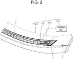
- FIGS. 1 and 2 are diagrams schematically illustrating that a lighting apparatus for a vehicle in accordance with an embodiment of the present disclosure is installed
- FIG. 3 is a perspective view schematically illustrating the configuration of the lighting apparatus for a vehicle in accordance with the embodiment of the present disclosure
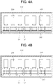
- FIGS. 4A and 4B are plan views schematically illustrating the configuration of the lighting apparatus for a vehicle in accordance with the embodiment of the present disclosure
- FIG. 5 is an expanded perspective view schematically illustrating the configuration of the lighting apparatus for a vehicle in accordance with the embodiment of the present disclosure.
- a lighting apparatus 1 for a vehicle in accordance with an embodiment of the present disclosure includes a housing 100, a light emitting unit 200, a flap unit 300, a display unit 400, a reflecting unit 500, a sensing unit 600, and a control unit 700.
- the housing 100 is installed inside the front surface of a vehicle 2, and serves to support the light emitting unit 200 and the flap unit 300 which will be described below.
- the housing 100 in accordance with the embodiment of the present disclosure is formed in a hollow box shape, and installed inside a bumper installed at the front surface of the vehicle 2.
- the specific shape of the housing 100 is not limited to that illustrated in FIGS. 1 to 5 , and may be variously changed in design as long as the housing 100 can be installed inside the front surface of the vehicle 2, and support the light emitting unit 200 and the flap unit 300 which will be described below.
- the housing 100 has an opening 101 formed on one side thereof.
- the opening 101 in accordance with the embodiment of the present disclosure is formed in the shape of a through-hole disposed at the front of the housing 100, and communicates the inside of the housing 100 with the outside of the front surface of the vehicle 2.
- the opening 101 has a cross-section corresponding to the cross-sectional shape of the front surface of the housing 100.
- the opening 101 is extended across the housing 100 in the widthwise direction of the housing 100, i.e. the side-to-side direction of the vehicle 2.
- the opening 101 may have a blocking part 102 installed at the front thereof, the blocking part 102 serving to prevent foreign matters such as dust and water from flowing into the housing 100.
- the blocking part 102 in accordance with the embodiment of the present disclosure is formed in the shape of a plate, and disposed so as to face the opening 101.
- the blocking part 102 may include a transparent material such as polycarbonate (PC) such that light emitted from the light emitting unit 200 to be described below can be transmitted to the outside of the vehicle.
- PC polycarbonate
- a pair of turn indicators 3 are installed on both sides of the top of the housing 100, and serve to inform a surrounding vehicle or pedestrian of the turning direction of the vehicle, while flickering in a preset period according to a driver's manipulation.
- a daytime running light 4 is installed, which is turned on separately from the light emitting unit 200 to be described below such that a surrounding vehicle or pedestrian can easily recognize the vehicle 2 during daytime operation.
- the light emitting unit 200 is installed inside the rear of the housing 100, and emits light toward the opening 101.
- the light emitting unit 200 may be installed in the housing 100 so as to be movable to the front or rear of the vehicle 2. Thus, the light emitting unit 200 may adjust a light distribution angle of the light emitted to the outside of the vehicle 2 through the opening 101.
- the light emitting unit 200 may be provided as a plurality of light emitting units which are arranged in two or more rows in the widthwise direction of the vehicle 2 and the housing 100.
- the plurality of light emitting units 200 may be each configured to individually adjust the turn-on state thereof.
- the plurality of light emitting units 200 may be sequentially or randomly turned on to transfer light emission signals to a surrounding vehicle, driver or pedestrian.
- the light emitting unit 200 in accordance with the embodiment of the present disclosure includes a light source 210, a heat sink 220, a reflector 230, and a lens 240.
- the light source 210 is installed on the heat sink 220 which will be described below, and can be turned on/off by power received from the outside.
- the light source 210 in accordance with the embodiment of the present disclosure may include one or more LEDs which are turned on/off by power received from the outside.
- the heat sink 220 supports the light source 210, and discharges heat, generated from the light source 210, to the outside of the housing 100.
- the heat sink 220 in accordance with the embodiment of the present disclosure is installed on the opposite side of the opening 101 inside the housing 100, i.e. at the rear of the housing 100.
- the light source 210 may be installed on the top surface of the heat sink 220.
- the heat sink 220 includes a plurality of heat radiation pins (not illustrated), and receives heat, generated by the turned-on light source 210, through thermal conduction.
- the heat sink 220 discharges heat, transferred to the plurality of heat radiation pins, to the outside of the housing 100 through the convective process with the outside of the housing 100.
- the reflector 230 is disposed so as to face the light source 210, and serves to reflect light, emitted from the light source 210, to one side.
- the reflector 230 in accordance with the embodiment of the present disclosure is formed in a spherical shape with a predetermined curvature, and has an inner surface facing the light source 210.
- the inner surface of the reflector 230 may include a high reflective material so as to reflect light emitted from the light source 210.
- the reflector 230 has an open front side, and reflects light, emitted from the light source 210, to the front of the housing 100.
- the lens 240 forms a light distribution pattern by transmitting the light, reflected from the reflector 230, toward the opening 101.
- the lens 240 in accordance with the embodiment of the present disclosure is disposed on a reflection path of light reflected from the reflector 230.
- the lens 240 is disposed between the opening 101 and the reflector 230, and spaced apart by a predetermined distance from the reflector 230 toward the front of the housing 100.
- the lens 240 may include a transparent material such as glass or plastic to transmit light reflected from the reflector 230.
- the lens 240 forms a light distribution pattern such as a low beam or high beam to the front of the vehicle 2 by transmitting light reflected from the reflector 230 to the opening 101.
- the specific shape of the lens 240 may be changed in design to the shapes of various types of lenses such as an aspherical lens, depending on a light emitting range, the light distribution pattern or the like.
- the flap unit 300 is rotatably installed in the housing 100 so as to open or close the opening 101.
- the flap unit 300 transfers a signal, formed by a motion thereof, to a surrounding vehicle, driver or pedestrian, while opening or closing the opening 101.
- the flap unit 300 can secure visibility even in a daytime situation in which light emitted through the light emitting unit 200 is hardly recognized.
- the flap unit 300 is disposed so as to face the light emitting unit 200, and thus interferes with light emitted from the light emitting unit 200. Therefore, the flap unit 300 may transfer more various types of signals with the light emitting unit 200, and vary the amount of light emitted from the light emitting unit 200, thereby further strengthening the visibility of the surrounding vehicle, driver or pedestrian.
- the flap unit 300 may be provided as a plurality of flap units which are arranged in two or more rows in the widthwise direction of the vehicle 2 and the housing 100.
- the plurality of flap units 300 may be each configured to individually adjust the rotation state thereof.
- the plurality of flap units 300 may transfer a predetermined direction signal to a pedestrian while being sequentially rotated.
- the flap units 300 may apply a shadow effect to light emitted from the light emitting unit 200 while being maintained at different rotation angles, thereby improving the visibility and aesthetic sensibility of the light emitted from the light emitting unit 200.
- the flap unit 300 in accordance with the embodiment of the present disclosure includes a rotating shaft 310, a flap member 320, and a driver 330.
- the rotating shaft 310 is rotatably installed in the housing 100, and serves to rotate the flap member 320 which will be described below.
- the rotating shaft 310 in accordance with the embodiment of the present disclosure is formed in the shape of a rotating shaft which is vertically extended across the housing 100 in the top-to-bottom direction.
- the rotating shaft 310 is disposed at the front of the housing 100 or more specifically between the opening 101 and the lens 240.
- the rotating shaft 310 is disposed at a position spaced apart by a predetermined distance from one end (left end in FIG. 5 ) of the lens 240.
- the rotating shaft 310 has a lower end connected to the driver 330, which will be described below, through the bottom surface of the housing 100.
- the flap member 320 is rotated on the rotating shaft 310 when the rotating shaft 310 is rotated.
- the flap member 320 in accordance with the embodiment of the present disclosure is formed in the shape of a plate having a rectangular cross-section, and has one end (left end in FIG. 5 ) connected to the outer circumferential surface of the rotating shaft 310.
- the front surface of the flap member 320 is disposed in parallel to the widthwise direction of the vehicle 2.
- the flap member 320 has a larger width than the lens 240, and thus can completely block light emitted from the lens 240 when the opening 101 is closed.
- the flap member 320 is rotated at a preset angle toward the inside of the housing 100, and thus opens the opening 101.
- the preset angle at which the flap member 320 is rotated to the inside of the housing 100 may be equal to or less than 90 degrees.
- the front surface of the flap member 320 may have a different color from the inside color of the housing 100, the surface color of the light emitting unit 200, or the color of light emitted from the light emitting unit 200, such that color inversion occurs when the flap member 320 is rotated.
- the flap member 320 may more effectively inform a surrounding vehicle, driver or pedestrian that the opening 101 is being opened/closed.
- a plurality of flap members 320 abut on the rotating shaft 310 to which the neighboring flap member 320 is connected. Therefore, when the opening 101 is closed, the flap member 320 may block lights, emitted from the plurality of light emitting units 200, from leaking to the outside.
- the driver 330 is connected to the rotating shaft 310, and generates a driving force to adjust the rotation angle and the rotation direction of the flap member 320.
- the driver 330 in accordance with the embodiment of the present disclosure may be configured as an electric motor which receives power from the outside and generates a rotational force.
- the driver 330 is fixed to the outer bottom surface of the housing 100, and has an output shaft connected to the bottom of the rotating shaft 310. Between the driver 330 and the rotating shaft 310, a reduction gear may be installed.
- the display unit 400 is installed in the housing 100 so as to display a preset color to the outside of the vehicle 2 as the flap unit 300 opens the opening 101.
- the display unit 400 in accordance with the embodiment of the present disclosure is disposed on the inner bottom surface of the housing 100, facing the rotation path of the lower end portion of the flap member 320.
- the display unit 400 is formed by coating the bottom surface of the housing 100 with a preset color. More specifically, the display unit 400 may be formed by applying a preset color of paint onto a bezel recessed into the bottom surface of the housing 100 or attaching a preset color of film onto the bezel.
- the display unit 400 may be formed by applying a preset color of paint onto the bottom surface of the housing 100 through a high glossy method, such that the preset color of paint exhibits a gloss.
- the display unit 400 may include a luminous or fluorescent material which absorbs light from the outside and discharges a longer wavelength of light than the wavelength of the absorbed light, such that the preset color can be displayed even in the nighttime.
- the preset color may be changed in design to various colors, as long as the color can be recognized from the outside of the vehicle 2 by a surrounding vehicle or pedestrian.
- the shape of the display unit 400 is not limited to that illustrated in FIG. 5 , but can be variously changed in design as long as the display unit 400 can display the preset color.
- the reflecting unit 500 is installed on the flap unit 300 so as to reflect the color displayed on the display unit 400 to the outside of the vehicle 2, when the flap unit 300 opens the opening 101.
- FIG. 6 is a perspective view schematically illustrating the configuration of the reflecting unit in accordance with the embodiment of the present disclosure.
- the reflecting unit 500 in accordance with the embodiment of the present disclosure is disposed on the front surface of the flap member 320 which vertically faces the display unit 400 when the opening 101 is opened.
- the reflecting unit 500 may be made of a high reflective material and formed as one body with the front surface of the flap member 320, or formed by coating the front surface of the flap member 320 with a high reflective material.
- FIG. 7 is a diagram schematically illustrating the configurations of the sensing unit and the control unit in accordance with the embodiment of the present disclosure.
- the sensing unit 600 is configured to sense the state around the vehicle, and sense the distance between the vehicle and a pedestrian or between the vehicle and a driver.
- the sensing unit 600 in accordance with the embodiment of the present disclosure may include a camera module 610, a distance sensor 620, and an illuminance sensor 630.
- the camera module 610 is installed on the front surface of the vehicle 2 or either side of the housing 100, and serves to acquire image data on a pedestrian or driver ahead of the vehicle 2 by capturing an image of the forward area of the vehicle 2.
- the distance sensor 620 senses the distance between the vehicle 2 and a pedestrian or driver.
- the distance sensor 620 may include one or more of various types of sensors such as a lidar sensor, a laser sensor and an ultrasonic wave sensor, which can measure a distance, and sense the distance between the vehicle 2 and a pedestrian or driver.
- the distance sensor 620 may sense the distance between the vehicle 2 and the driver through a portable terminal carried by the driver.
- the portable terminal may be exemplified as a smart key for a vehicle. More specifically, the distance sensor 620 may include a GPS (Global Positioning System), and sense the relative bearing and relative distance of the driver's portable terminal with respect to the vehicle 2. Furthermore, when an RKE (Remote Keyless Entry) or PKE (Passive Keyless Entry) signal for wirelessly opening or closing the door of the vehicle from a remote location is received from the portable terminal of the driver, the distance sensor 620 may sense that the driver has approached the vehicle 2 within a predetermined distance.
- RKE Remote Keyless Entry
- PKE Passive Keyless Entry
- the illuminance sensor 630 is installed in the vehicle 2, and serves to sense the brightness (illuminance) value around the vehicle 2.
- the control unit 700 receives the sensed information from the sensing unit 600, and transmits a light emitting unit turn-on signal for turning on the light emitting unit 200 and a flap unit control signal for rotating the flap unit 300. More specifically, when the distance between the vehicle 2 and a pedestrian falls within a first distance, the control unit 700 transmits the light emitting unit turn-on signal and the flap unit control signal to the light emitting unit 200 and the flap unit 300, respectively, such that the light emitting unit 200 and the flap unit 300 indicate a walking direction to the pedestrian.
- the control unit 700 transmits the light emitting unit turn-on signal and the flap unit control signal to the light emitting unit 200 and the flap unit 300, respectively, such that the light emitting unit 200 and the flap unit 300 generate a welcome signal.
- the control unit 700 transmits the light emitting unit turn-on signal and the flap unit control signal to the light emitting unit 200 and the flap unit 300, respectively, such that the light emitting unit 200 and the flap unit 300 generate a goodbye signal.
- the first distance and the second distance may be changed in design to various values within the range of separation distances from the vehicle 2.
- the control unit 700 in accordance with the embodiment of the present disclosure may be exemplified as a microprocessor or ECU (Electronic Control Unit) which is connected to the light emitting unit 200 and the driver 330, and receives the sensed information from the sensing unit 600, and transmits the light emitting unit turn-on signal and the flap unit control signal to the light emitting unit 200 and the flap unit 300, respectively.
- ECU Electronic Control Unit
- FIG. 8 shows that the control method is divided into a plurality of steps. However, the order of at least some steps may be changed, at least some steps may be each combined with another step, or omitted or divided into sub steps, or one or more steps (not illustrated) may be added.
- FIG. 8 is a flowchart schematically illustrating a control method of a lighting apparatus for a vehicle in accordance with an embodiment of the present disclosure
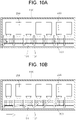
- FIGS. 9 , 10A and 10B are operation diagrams schematically illustrating an operation process of the control method of a lighting apparatus for a vehicle in accordance with the embodiment of the present disclosure.
- the sensing unit 600 senses the distance between the vehicle 2 and a pedestrian in step S110. More specifically, the sensing unit 600 recognizes a pedestrian ahead of the vehicle 2 through the camera module 610, and measures the distance from the vehicle 2 to the pedestrian through the distance sensor 620.
- the control unit 700 determines whether the vehicle 2 is traveling, in step S120. More specifically, the control unit 700 determines whether the vehicle 2 is traveling, on the basis of whether the ignition switch of the vehicle 2 is turned on/off, a gear operating state of the vehicle 2, and whether an autonomous driving mode is turned on/off.
- the control unit 700 turns on or off the light emitting unit 200 on the basis of a preset illuminance value outside the vehicle 2, in step S130. More specifically, when the illuminance value outside the vehicle, measured by the illuminance sensor 630, is equal to or less than the preset illuminance value, the control unit 700 transmits the light emitting unit turn-on signal to the light emitting unit 200 in order to turn on the light emitting unit 200, in step S131. Simultaneously, the control unit 700 opens the opening 101 by rotating the flap unit 300.
- the control unit 700 stops transmitting the light emitting unit turn-on signal to the light emitting unit 200, and thus turns off the light emitting unit 200, in step S132.
- the operation of turning off the light emitting unit 200 may indicate an operation of not only turning off the turned-on light emitting unit 200, but also maintaining the turned-off light emitting unit 200.
- the preset illuminance value may be changed in design to various values in consideration of a driver's visibility.
- steps S120 and S130 may be sequentially performed after step S110.
- steps S120 and 130 may be performed at the same time as step S110, or in a different order from step S110.
- step S120 When it is determined in step S120 that the vehicle 2 is traveling, the control unit 700 determines whether the distance between the vehicle 2 and the pedestrian, sensed in step S110, falls within the first distance, in step S140.
- step S140 When it is determined in step S140 that the distance between the vehicle 2 and the pedestrian falls within the first distance, the control unit 700 determines the walking direction of the pedestrian in step S150.
- the control unit 700 After determining the walking direction of the pedestrian in step S150, the control unit 700 operates the flap unit 300 to indicate the walking direction to the pedestrian, in step S160. More specifically, the control unit 700 transmits the flap unit control signal to the flap unit 300 to sequentially rotate the flap units 300 in a direction parallel to the walking direction of the pedestrian.
- the plurality of flap units 300 indicate the walking direction to the pedestrian while opening or closing the opening 101 in the direction parallel to the walking direction of the pedestrian.
- the control unit 700 sequentially operates a plurality of drivers 330 from the driver 330 disposed at the leftmost position to the driver 330 disposed at the rightmost position, as illustrated in FIGS. 10A and 10B .
- the plurality of flap members 320 are sequentially rotated from the flap member 320 disposed at the leftmost position to the flap member 320 disposed at the rightmost position.
- the flap members 320 transfer a walking signal for instructing the pedestrian to walk from left to right, while sequentially closing the opening 101 from left to right.
- color inversion occurs because the front surface of the flap member 320 has a different color from the inside color of the housing 100, the surface color of the light emitting unit 200, or the color of light emitted from the light emitting unit 200.
- the display unit 400 displays a preset color to the outside of the vehicle 2
- the reflecting unit 500 reflects the preset color, displayed by the display unit 400, toward the outside of the vehicle 2.
- FIG. 11 is a flowchart schematically illustrating a control method of a lighting apparatus for a vehicle in accordance with another embodiment of the present disclosure.
- the sensing unit 600 senses the distance between the vehicle 2 and a driver in step S210. More specifically, the sensing unit 600 senses the distance between the vehicle 2 and a portable terminal carried by the driver through the distance sensor 620.
- the distance sensor 620 may include a GPS to sense the relative bearing and relative distance of the driver's portable terminal with respect to the vehicle 2.
- an RKE (Remote Keyless Entry) or PKE (Passive Keyless Entry) signal for wirelessly opening or closing the door of the vehicle from a remote location is received from the portable terminal of the driver, the distance sensor 620 may sense that the driver has approached the vehicle 2 within a predetermined distance.
- the control unit 700 determines whether the distance between the vehicle 2 and the driver, sensed in step S210, falls within the second distance, in step S220.
- control unit 700 determines whether the ignition switch of the vehicle 2 is turned on/off, in step S230.
- control unit 700 When determining in step S230 that the ignition switch of the vehicle 2 is turned on, the control unit 700 operate the flap unit 300 and the light emitting unit 200 to generate a welcome signal in step S240.
- the control unit 700 may flicker the turn indicator 3 a preset number of times before operating the flap unit 300 and the light emitting unit 200. The present number of times may be exemplified as two.
- FIG. 12 is a flowchart schematically illustrating a process in which the flap unit and the light emitting unit generate a welcome signal, in accordance with the embodiment of the present disclosure.
- step S240 of generating the welcome signal includes a first welcome step S241, a second welcome step S242, a third welcome step S243, and a fourth welcome step S244.
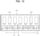
- FIG. 13 is an operation diagram schematically illustrating an operation process of the first welcome step in accordance with the embodiment of the present disclosure.
- the control unit 700 opens the opening 101 by sequentially rotating the plurality of flap units 300 from the center of the opening 101 toward both ends of the opening 101. More specifically, the control unit 700 first rotates the flap unit 300 disposed in the center of the opening 101. Then, the control unit 700 sequentially rotates the flap units 300 disposed on the left and right sides of the flap unit 300 disposed in the center of the opening 101, with a predetermined time difference provided therebetween. Thus, the opening 101 is opened in such a shape that spreads from the center thereof toward both ends thereof.
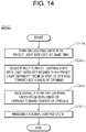
- FIG. 14 is a flowchart schematically illustrating the second welcome step in accordance with the embodiment of the present disclosure
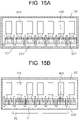
- FIGS. 15A to 15D are an operation diagram schematically illustrating the operation process of the second welcome step in accordance with the embodiment of the present disclosure.
- control unit 700 turns on and off the plurality of light emitting units 200 with the opening 101 opened by the flap units 300.
- control unit 700 turns on the plurality of light emitting units 200 with a preset light intensity at the same time in step S242a.
- the preset light intensity may be exemplified as 70% of the maximum light intensity of the light emitting unit 200.
- the control unit 700 sequentially turns on the plurality of light emitting units 200 from the center of the opening 101 toward both ends thereof with a light intensity higher than the preset light intensity, in step S242b. That is, the control unit 700 sequentially turns on the light emitting units 200 disposed on the left and right sides of the light emitting unit 200 disposed in the center of the opening 101 with a light intensity higher than the preset light intensity, with predetermined time differences provided therebetween. Therefore, the light emitting units 200 are turned on in such a shape that spreads from the center toward both ends of the opening 101. In this case, the light intensity higher than the preset light intensity may be exemplified as the maximum light intensity of the light emitting unit 200.
- the control unit 700 sequentially turns off the plurality of light emitting units 200 from both ends of the opening 101 toward the center of the opening 101 in step S242c. That is, the control unit 700 sequentially turns off the plurality of light emitting units 200 from the light emitting units 200 disposed at both ends of the opening 101 toward the light emitting unit 200 disposed in the center of the opening 101, with predetermined timed differences provided therebetween.
- the light emitting units 200 are turned off in such a shape that converges from both ends of the opening 101 toward the center of the opening 101.
- the control unit 700 randomly flickers the plurality of light emitting units 200. That is, the control unit 700 turns on some light emitting units 200, which are randomly selected while the plurality of light emitting units 200 are all turned off, and then turns off the some light emitting units 200.
- FIG. 16 is an operation diagram schematically illustrating an operation process of the third welcome step in accordance with the embodiment of the present disclosure.
- the control unit 700 closes the opening 101 by sequentially rotating the plurality of flap units 300 from both ends of the opening 101 toward the center of the opening 101. More specifically, while the opening 101 is opened, the control unit 700 rotates the plurality of flap units 300 from the flap units 300 disposed at both ends of the opening 101 toward the flap unit 300 disposed in the center of the opening 101, with predetermined time differences provided therebetween. Therefore, the opening 101 is closed in such a shape that converges from both ends thereof toward the center thereof.
- FIG. 17 is an operation diagram schematically illustrating an operation process of the fourth welcome step in accordance with the embodiment of the present disclosure.
- the control unit 700 opens the opening 101 by rotating the plurality of flap units 300 at the same time, and turns on the plurality of light emitting units 200 at the same time. That is, the control unit 700 rotates the plurality of flap units 300 such that the opening 101 closed by the plurality of flap units 300 is opened at once in the widthwise direction of the housing 100, and turns on the plurality of light emitting units 200 such that lights are simultaneously emitted to the outside of the vehicle through the opening 101.
- the light intensities of the light emitting units 200 may gradually rise to the maximum light intensity with a predetermined time difference.
- the control unit 700 may additionally perform a step of closing the opening 101 by rotating the plurality of flap units 300 at the same time, and turning off the plurality of light emitting units 200 at the same time.
- control unit 700 determines whether the ignition switch of the vehicle 2 is turned on/off, in step S250.
- control unit 700 When determining in step S250 that the ignition switch of the vehicle 2 is turned off, the control unit 700 operate the flap unit 300 and the light emitting unit 200 to generate a goodbye signal in step S260.
- the control unit 700 may flicker the turn indicator 3 a preset number of times before operating the flap unit 300 and the light emitting unit 200. The present number of times may be exemplified as two.
- FIG. 18 is a flowchart schematically illustrating a process in which the flap unit and the light emitting unit generate a goodbye signal, in accordance with the embodiment of the present disclosure.
- Step S260 of generating the goodbye signal includes a first goodbye step S261 and a second goodbye step S262.
- FIG. 19 is an operation diagram schematically illustrating the operation process of the first goodbye step in accordance with the embodiment of the present disclosure.
- the control unit 700 sequentially turns off the plurality of light emitting units 200 from both ends of the opening 101 toward the center of the opening 101. That is, the control unit 700 sequentially turns off the plurality of light emitting units 200 from the light emitting units 200 disposed at both ends of the opening 101 toward the light emitting unit 200 disposed in the center of the opening 101, with predetermined time differences provided therebetween.
- the light emitting units 200 are turned off in such a shape that converges from both ends of the opening 101 toward the center of the opening 101.
- FIG. 20 is an operation diagram schematically illustrating an operation process of the second goodbye step in accordance with the embodiment of the present disclosure.
- the control unit 700 closes the opening 101 by sequentially rotating the plurality of flap units 300 from both ends of the opening 101 toward the center of the opening 101. More specifically, while the opening 101 is opened, the control unit 700 rotates the plurality of flap units 300 from the flap units 300 disposed at both ends of the opening 101 toward the flap unit 300 disposed in the center of the opening 101, with predetermined time differences provided therebetween. Therefore, the opening 101 is closed in such a shape that converges from both ends thereof toward the center thereof.
- control unit 700 may additionally perform a step of turning off the daytime running light 4.
Landscapes
- Engineering & Computer Science (AREA)
- Mechanical Engineering (AREA)
- General Engineering & Computer Science (AREA)
- Automation & Control Theory (AREA)
- Physics & Mathematics (AREA)
- Multimedia (AREA)
- Theoretical Computer Science (AREA)
- General Physics & Mathematics (AREA)
- Human Computer Interaction (AREA)
- Transportation (AREA)
- Microelectronics & Electronic Packaging (AREA)
- Optics & Photonics (AREA)
- Lighting Device Outwards From Vehicle And Optical Signal (AREA)
Abstract
Description
- Exemplary embodiments of the present disclosure relate to a lighting apparatus for a vehicle and a control method thereof, and more particularly, to a lighting apparatus for a vehicle, which can transfer a signal to a surrounding vehicle, driver or pedestrian, and a control method thereof.
- In general, a vehicle includes various types of lighting apparatuses which allow a driver to easily check a target located around the vehicle during driving, and serve to inform a surrounding vehicle or pedestrian of the state of the vehicle or to transfer a signal to the surrounding vehicle or pedestrian.
- However, the conventional lighting apparatuses transfer signals only by turning on/off LEDs, and thus have a limit to the types of signals that the lighting apparatuses can transfer. Furthermore, since the conventional lighting apparatuses can transfer only two-dimensional images, it is difficult for the lighting apparatuses to clearly transfer signals. Furthermore, when the lighting apparatuses transfer signals only by turning on/off LEDs in the daytime during which the illuminance outside the vehicle is high, the visibility is reduced.
- The related art of the present disclosure is disclosed in
Korean Patent No. 10-1789652 registered on October 18, 2017 - Various embodiments are directed to a lighting apparatus for a vehicle, which can transfer a motion signal generated by a motion as well as a light emission signal generated by light, and a control method thereof.
- In an embodiment, a lighting apparatus for a vehicle may include a housing installed at the front surface of a vehicle, and having an opening formed on one side thereof; a plurality of light emitting units installed in the housing, and configured to emit light toward the opening; and a plurality of flap units rotatably installed in the housing so as to open or close the opening, and disposed so as to face the light emitting units.
- The plurality of light emitting units and the plurality of flap units may be arranged in two or more rows in the widthwise direction of the vehicle.
- The plurality of light emitting units may be each configured to individually adjust the turn-on state thereof, and the plurality of flap units may be each configured to individually adjust the rotation state thereof.
- The flap units may each include a flap member rotated on a rotating shaft extended across the housing in a top-to-bottom direction; and a driver connected to the rotating shaft, and configured to generate a driving force to adjust the rotation angle and the rotation direction of the flap member.
- As the flap member is rotated at a preset angle to the inside of the housing while the front surface of the flap member is disposed in parallel to the widthwise direction of the vehicle, the opening may be opened.
- The preset angle at which the flap member is rotated to the inside of the housing may be equal to or less than 90 degrees.
- The front surface of the flap member may have a different color from the inside color of the housing or the surface color of the light emitting unit, such that color inversion occurs when the flap member is rotated.
- The light emitting unit may be installed in the housing so as to move to the front or read of the vehicle.
- The light emitting unit may include a light source turned on or off; a heat sink configured to support the light source, and discharge heat generated from the light source; a reflector configured to reflect light, emitted from the light source, to one side; and a lens configured to form a light distribution pattern by transmitting the light, reflected from the reflector, toward the opening.
- The lighting apparatus may further include a display unit installed on the housing, and configured to display a preset color to the outside of the vehicle as the flap unit opens the opening.
- The display unit may be formed by coating the inner surface of the housing with the preset color of paint.
- The display unit may include a luminous or fluorescent material.
- The lighting apparatus may further include a reflecting unit installed on the flap unit and configured to reflect the color displayed on the display unit to the outside of the vehicle, when the flap unit opens the opening.
- The lighting apparatus may further include: a sensing unit configured to sense the distance between the vehicle and a pedestrian or driver; and a control unit configured to receive the sensed information from the sensing unit, and transmit a light emitting unit turn-on signal for turning on the light emitting unit and a flap unit control signal for rotating the flap unit.
- When the distance between the vehicle and the pedestrian falls within a first distance, the control unit may transmit the light emitting unit turn-on signal and the flap unit control signal to the light emitting unit and the flap unit, respectively, such that the light emitting unit and the flap unit indicate a walking direction to the pedestrian.
- When the distance between the vehicle and the driver falls within a second distance, the control unit may transmit the light emitting unit turn-on signal and the flap unit control signal to the light emitting unit and the flap unit, respectively, such that the light emitting unit and the flap unit generate a welcome signal.
- When the distance between the vehicle and the driver exceeds the second distance, the control unit may transmit the light emitting unit turn-on signal and the flap unit control signal to the light emitting unit and the flap unit, respectively, such that the light emitting unit and the flap unit generate a goodbye signal.
- In an embodiment, a control method of a lighting apparatus for a vehicle may include: sensing, by a sensing unit, a distance between the vehicle and a pedestrian; determining, by a control unit, whether the distance between the vehicle and the pedestrian falls within a first distance; determining, by the control unit, a walking direction of the pedestrian when the distance between the vehicle and the pedestrian falls within the first distance; and indicating, by the control unit, the walking direction to the pedestrian by operating a plurality of flap units.
- In the indicating of the walking direction, the plurality of flap units may open or close an opening while sequentially rotated in a direction parallel to the walking direction of the pedestrian.
- As the flap units open or close the opening, color inversion may occur.
- When the flap units open the opening, a display unit may display a preset color to an outside of the vehicle, and a reflecting unit may reflect the preset color, displayed by the display unit, toward the outside of the vehicle.
- The control method may further include determining, by the control unit, whether the vehicle is traveling.
- The control method may further include turning on/off, by the control unit, a light emitting unit on the basis of a preset illuminance value outside the vehicle.
- In an embodiment, a control method of a lighting apparatus for a vehicle may include: sensing, by a sensing unit, a distance between the vehicle and a driver; determining, by a control unit, whether the distance between the vehicle and the driver falls within a second distance; generating, by the control unit, a welcome signal by operating a plurality of flap units and a plurality of light emitting units, when the distance between the vehicle and the driver falls within the second distance; and generating, by the control unit, a goodbye signal by operating the flap units and the light emitting units, when the distance between the vehicle and the driver exceeds the second distance.
- The control method may further include determining, by the control unit, whether an ignition switch of the vehicle is turned on/off.
- The generating of the welcome signal may include: a first welcome step in which the plurality of flap units open an opening while sequentially rotated from a center of the opening toward both ends of the opening, when the ignition switch of the vehicle is turned on; a second welcome step in which the plurality of light emitting units are turned on and off while the opening is opened; a third welcome step in which the plurality of flap units close the opening while sequentially rotated from both ends of the opening toward the center of the opening; and a fourth welcome step in which the plurality of flap units open the opening while rotated at the same time, and the plurality of light emitting units are turned on at the same time.
- The second welcome step may include: turning on the plurality of light emitting units with a preset light intensity at the same time; sequentially turning on the plurality of light emitting units from the center of the opening toward both ends of the opening with a light intensity higher than the preset light intensity; sequentially turning off the plurality of light emitting units from both ends of the opening toward the center of the opening; and randomly flickering the plurality of light emitting units.
- The generating of the welcome signal may further include turning off, by the control unit, the plurality of light emitting units at the same time when an illuminance value outside the vehicle exceeds a preset illuminance value after the fourth welcome step.
- The generating of the welcome signal may further include flicking, by the control unit, a turn indicator a preset number of times before operating the flap units and the light emitting unit.
- The generating of the goodbye signal may include: a first goodbye step of sequentially turning off the plurality of light emitting units from both ends of an opening toward the center of the opening, when the ignition switch of the vehicle is turned off; and a second goodbye step of closing, by the plurality of flap units, the opening while the plurality of flap units are sequentially rotated from both ends of the opening toward the center of the opening.
- The generating of the goodbye signal may further include flicking, by the control unit, a turn indicator a preset number of times before operating the flap units and the light emitting unit.
- As the flap units open or close an opening, color inversion may occur.
- When the flap units open an opening, a display unit may display a preset color to an outside of the vehicle, and a reflecting unit may reflect the preset color, displayed by the display unit, to the outside of the vehicle.
- In accordance with the embodiment of the present disclosure, the lighting apparatus for a vehicle may transmit various types of signals to a surrounding vehicle, driver or pedestrian by combining a light emission signal generate by the light emitting units and a motion signal generated by the flap units, and strengthen the visibility in a daytime situation.
- Furthermore, the lighting apparatus may implement a dynamic image by individually adjusting the turn-on states of the plurality of light emitting units and the rotation states of the plurality of flap units, thereby transmitting a more efficient and intuitive signal.
- Furthermore, in the lighting apparatus, the flap units may be disposed so as to interfere with light emitted from the light emitting units. Therefore, the flap units may apply a shadow effect to a light emission signal, thereby improving the aesthetic sensibility of the light emission signal.
- Furthermore, when the opening is opened, the display unit may display a preset color to the outside of the vehicle, which makes it possible to transfer a clearer signal to a surrounding vehicle, driver or pedestrian.
- Furthermore, the reflecting unit may reflect the preset color displayed on the display unit, which makes it possible to secure the visibility while displaying a high quality image.
- The control method of the lighting apparatus for a vehicle in accordance with the embodiment of the present disclosure may indicate a walking direction by operating the flap units and the lighting units on the basis of the distance between the vehicle and a pedestrian and the walking direction of the pedestrian, thereby transferring a clearer signal, and preventing a safety accident caused by a disagreement in communication with the pedestrian.
- The control method of the lighting apparatus for a vehicle in accordance with the embodiment of the present disclosure may generate a welcome signal and a goodbye signal by operating the flap units and the light emitting units on the basis of the distance between the vehicle and a driver, which makes it possible for the driver to more easily recognize the location of the vehicle, and to check the state of the vehicle such as a start-up of the vehicle from a remote location.
-
-
FIGS. 1 and2 are diagrams schematically illustrating that a lighting apparatus for a vehicle in accordance with an embodiment of the present disclosure is installed. -
FIG. 3 is a perspective view schematically illustrating the configuration of the lighting apparatus for a vehicle in accordance with the embodiment of the present disclosure. -
FIGS. 4A and 4B are plan views schematically illustrating the configuration of the lighting apparatus for a vehicle in accordance with the embodiment of the present disclosure. -
FIG. 5 is an expanded perspective view schematically illustrating the configuration of the lighting apparatus for a vehicle in accordance with the embodiment of the present disclosure. -
FIG. 6 is a perspective view schematically illustrating the configuration of a reflecting unit in accordance with the embodiment of the present disclosure. -
FIG. 7 is a diagram schematically illustrating the configurations of a sensing unit and a control unit in accordance with the embodiment of the present disclosure. -
FIG. 8 is a flowchart schematically illustrating a control method of a lighting apparatus for a vehicle in accordance with an embodiment of the present disclosure. -
FIGS. 9 ,10A and 10B are operation diagrams schematically illustrating an operation process of the control method of a lighting apparatus for a vehicle in accordance with the embodiment of the present disclosure. -
FIG. 11 is a flowchart schematically illustrating a control method of a lighting apparatus for a vehicle in accordance with another embodiment of the present disclosure. -
FIG. 12 is a flowchart schematically illustrating a process in which a flap unit and a light emitting unit generate a welcome signal, in accordance with an embodiment of the present disclosure. -
FIG. 13 is an operation diagram schematically illustrating an operation process of a first welcome step in accordance with the embodiment of the present disclosure. -
FIG. 14 is a flowchart schematically illustrating a second welcome step in accordance with the embodiment of the present disclosure. -
FIGS. 15A to 15D are operation diagrams schematically illustrating an operation process of the second welcome step in accordance with the embodiment of the present disclosure. -
FIG. 16 is an operation diagram schematically illustrating an operation process of a third welcome step in accordance with the embodiment of the present disclosure. -
FIG. 17 is an operation diagram schematically illustrating an operation process of a fourth welcome step in accordance with the embodiment of the present disclosure. -
FIG. 18 is a flowchart schematically illustrating a process in which the flap unit and the light emitting unit generate a goodbye signal, in accordance with the embodiment of the present disclosure. -
FIG. 19 is an operation diagram schematically illustrating an operation process of a first goodbye step in accordance with the embodiment of the present disclosure. -
FIG. 20 is an operation diagram schematically illustrating an operation process of a second goodbye step in accordance with the embodiment of the present disclosure. - Hereinafter, a lighting apparatus for a vehicle and a control method thereof will be described below with reference to the accompanying drawings through various exemplary embodiments.
- It should be noted that the drawings are not to precise scale and may be exaggerated in thickness of lines or sizes of components for descriptive convenience and clarity only. Furthermore, the terms as used herein are defined by taking functions of the invention into account and can be changed according to the custom or intention of users or operators. Therefore, definition of the terms should be made according to the overall disclosures set forth herein.
- Throughout the specification, when one element is referred to as being "connected to" or "coupled to" another element, it may indicate that the one element is "directly connected or coupled to" the another element or the one element is "indirectly connected or coupled to" with still another element interposed therebetween. In this specification, when an element "includes or has" a component, it may indicate that the element does not exclude another component, but can further include or have another component, unless referred to the contrary.
- Through this specification, like reference numerals may represent the same components. Although like or similar reference numbers are not mentioned or described in a specific drawing, the reference numerals may be described with reference to other drawings. Furthermore, although a component is not represented by a reference numeral in a specific drawing, the component may be described with reference to other drawings. Furthermore, the number, shape and size of sub components included in the drawings of this specification and the relative difference between sizes are set for convenience of description, and may not limit embodiments but may be set to various values.
-
FIGS. 1 and2 are diagrams schematically illustrating that a lighting apparatus for a vehicle in accordance with an embodiment of the present disclosure is installed,FIG. 3 is a perspective view schematically illustrating the configuration of the lighting apparatus for a vehicle in accordance with the embodiment of the present disclosure,FIGS. 4A and 4B are plan views schematically illustrating the configuration of the lighting apparatus for a vehicle in accordance with the embodiment of the present disclosure, andFIG. 5 is an expanded perspective view schematically illustrating the configuration of the lighting apparatus for a vehicle in accordance with the embodiment of the present disclosure. - Referring to
FIGS. 1 to 5 , alighting apparatus 1 for a vehicle in accordance with an embodiment of the present disclosure includes ahousing 100, alight emitting unit 200, aflap unit 300, adisplay unit 400, a reflectingunit 500, asensing unit 600, and acontrol unit 700. - The
housing 100 is installed inside the front surface of avehicle 2, and serves to support thelight emitting unit 200 and theflap unit 300 which will be described below. Thehousing 100 in accordance with the embodiment of the present disclosure is formed in a hollow box shape, and installed inside a bumper installed at the front surface of thevehicle 2. The specific shape of thehousing 100 is not limited to that illustrated inFIGS. 1 to 5 , and may be variously changed in design as long as thehousing 100 can be installed inside the front surface of thevehicle 2, and support thelight emitting unit 200 and theflap unit 300 which will be described below. - The
housing 100 has anopening 101 formed on one side thereof. Theopening 101 in accordance with the embodiment of the present disclosure is formed in the shape of a through-hole disposed at the front of thehousing 100, and communicates the inside of thehousing 100 with the outside of the front surface of thevehicle 2. Theopening 101 has a cross-section corresponding to the cross-sectional shape of the front surface of thehousing 100. Theopening 101 is extended across thehousing 100 in the widthwise direction of thehousing 100, i.e. the side-to-side direction of thevehicle 2. - The
opening 101 may have a blockingpart 102 installed at the front thereof, the blockingpart 102 serving to prevent foreign matters such as dust and water from flowing into thehousing 100. The blockingpart 102 in accordance with the embodiment of the present disclosure is formed in the shape of a plate, and disposed so as to face theopening 101. The blockingpart 102 may include a transparent material such as polycarbonate (PC) such that light emitted from thelight emitting unit 200 to be described below can be transmitted to the outside of the vehicle. - A pair of
turn indicators 3 are installed on both sides of the top of thehousing 100, and serve to inform a surrounding vehicle or pedestrian of the turning direction of the vehicle, while flickering in a preset period according to a driver's manipulation. - Between the pair of
turn indicators 3, adaytime running light 4 is installed, which is turned on separately from thelight emitting unit 200 to be described below such that a surrounding vehicle or pedestrian can easily recognize thevehicle 2 during daytime operation. - The
light emitting unit 200 is installed inside the rear of thehousing 100, and emits light toward theopening 101. Thelight emitting unit 200 may be installed in thehousing 100 so as to be movable to the front or rear of thevehicle 2. Thus, thelight emitting unit 200 may adjust a light distribution angle of the light emitted to the outside of thevehicle 2 through theopening 101. Thelight emitting unit 200 may be provided as a plurality of light emitting units which are arranged in two or more rows in the widthwise direction of thevehicle 2 and thehousing 100. The plurality of light emittingunits 200 may be each configured to individually adjust the turn-on state thereof. Thus, the plurality of light emittingunits 200 may be sequentially or randomly turned on to transfer light emission signals to a surrounding vehicle, driver or pedestrian. - The
light emitting unit 200 in accordance with the embodiment of the present disclosure includes alight source 210, aheat sink 220, areflector 230, and alens 240. - The
light source 210 is installed on theheat sink 220 which will be described below, and can be turned on/off by power received from the outside. Thelight source 210 in accordance with the embodiment of the present disclosure may include one or more LEDs which are turned on/off by power received from the outside. - The
heat sink 220 supports thelight source 210, and discharges heat, generated from thelight source 210, to the outside of thehousing 100. Theheat sink 220 in accordance with the embodiment of the present disclosure is installed on the opposite side of theopening 101 inside thehousing 100, i.e. at the rear of thehousing 100. Thelight source 210 may be installed on the top surface of theheat sink 220. Theheat sink 220 includes a plurality of heat radiation pins (not illustrated), and receives heat, generated by the turned-onlight source 210, through thermal conduction. Theheat sink 220 discharges heat, transferred to the plurality of heat radiation pins, to the outside of thehousing 100 through the convective process with the outside of thehousing 100. - The
reflector 230 is disposed so as to face thelight source 210, and serves to reflect light, emitted from thelight source 210, to one side. Thereflector 230 in accordance with the embodiment of the present disclosure is formed in a spherical shape with a predetermined curvature, and has an inner surface facing thelight source 210. The inner surface of thereflector 230 may include a high reflective material so as to reflect light emitted from thelight source 210. Thereflector 230 has an open front side, and reflects light, emitted from thelight source 210, to the front of thehousing 100. - The
lens 240 forms a light distribution pattern by transmitting the light, reflected from thereflector 230, toward theopening 101. Thelens 240 in accordance with the embodiment of the present disclosure is disposed on a reflection path of light reflected from thereflector 230. Thelens 240 is disposed between theopening 101 and thereflector 230, and spaced apart by a predetermined distance from thereflector 230 toward the front of thehousing 100. Thelens 240 may include a transparent material such as glass or plastic to transmit light reflected from thereflector 230. Thelens 240 forms a light distribution pattern such as a low beam or high beam to the front of thevehicle 2 by transmitting light reflected from thereflector 230 to theopening 101. The specific shape of thelens 240 may be changed in design to the shapes of various types of lenses such as an aspherical lens, depending on a light emitting range, the light distribution pattern or the like. - The
flap unit 300 is rotatably installed in thehousing 100 so as to open or close theopening 101. Theflap unit 300 transfers a signal, formed by a motion thereof, to a surrounding vehicle, driver or pedestrian, while opening or closing theopening 101. Thus, theflap unit 300 can secure visibility even in a daytime situation in which light emitted through thelight emitting unit 200 is hardly recognized. When opening or closing theopening 101, theflap unit 300 is disposed so as to face thelight emitting unit 200, and thus interferes with light emitted from thelight emitting unit 200. Therefore, theflap unit 300 may transfer more various types of signals with thelight emitting unit 200, and vary the amount of light emitted from thelight emitting unit 200, thereby further strengthening the visibility of the surrounding vehicle, driver or pedestrian. Theflap unit 300 may be provided as a plurality of flap units which are arranged in two or more rows in the widthwise direction of thevehicle 2 and thehousing 100. The plurality offlap units 300 may be each configured to individually adjust the rotation state thereof. Thus, the plurality offlap units 300 may transfer a predetermined direction signal to a pedestrian while being sequentially rotated. Furthermore, theflap units 300 may apply a shadow effect to light emitted from thelight emitting unit 200 while being maintained at different rotation angles, thereby improving the visibility and aesthetic sensibility of the light emitted from thelight emitting unit 200. - The
flap unit 300 in accordance with the embodiment of the present disclosure includes arotating shaft 310, aflap member 320, and adriver 330. - The
rotating shaft 310 is rotatably installed in thehousing 100, and serves to rotate theflap member 320 which will be described below. Therotating shaft 310 in accordance with the embodiment of the present disclosure is formed in the shape of a rotating shaft which is vertically extended across thehousing 100 in the top-to-bottom direction. Therotating shaft 310 is disposed at the front of thehousing 100 or more specifically between theopening 101 and thelens 240. Therotating shaft 310 is disposed at a position spaced apart by a predetermined distance from one end (left end inFIG. 5 ) of thelens 240. Therotating shaft 310 has a lower end connected to thedriver 330, which will be described below, through the bottom surface of thehousing 100. - The
flap member 320 is rotated on therotating shaft 310 when therotating shaft 310 is rotated. Theflap member 320 in accordance with the embodiment of the present disclosure is formed in the shape of a plate having a rectangular cross-section, and has one end (left end inFIG. 5 ) connected to the outer circumferential surface of therotating shaft 310. When theopening 101 is closed, the front surface of theflap member 320 is disposed in parallel to the widthwise direction of thevehicle 2. Theflap member 320 has a larger width than thelens 240, and thus can completely block light emitted from thelens 240 when theopening 101 is closed. Theflap member 320 is rotated at a preset angle toward the inside of thehousing 100, and thus opens theopening 101. The preset angle at which theflap member 320 is rotated to the inside of thehousing 100 may be equal to or less than 90 degrees. The front surface of theflap member 320 may have a different color from the inside color of thehousing 100, the surface color of thelight emitting unit 200, or the color of light emitted from thelight emitting unit 200, such that color inversion occurs when theflap member 320 is rotated. Thus, theflap member 320 may more effectively inform a surrounding vehicle, driver or pedestrian that theopening 101 is being opened/closed. When theopening 101 is closed, a plurality offlap members 320 abut on therotating shaft 310 to which the neighboringflap member 320 is connected. Therefore, when theopening 101 is closed, theflap member 320 may block lights, emitted from the plurality of light emittingunits 200, from leaking to the outside. - The
driver 330 is connected to therotating shaft 310, and generates a driving force to adjust the rotation angle and the rotation direction of theflap member 320. Thedriver 330 in accordance with the embodiment of the present disclosure may be configured as an electric motor which receives power from the outside and generates a rotational force. Thedriver 330 is fixed to the outer bottom surface of thehousing 100, and has an output shaft connected to the bottom of therotating shaft 310. Between thedriver 330 and therotating shaft 310, a reduction gear may be installed. - The
display unit 400 is installed in thehousing 100 so as to display a preset color to the outside of thevehicle 2 as theflap unit 300 opens theopening 101. Thedisplay unit 400 in accordance with the embodiment of the present disclosure is disposed on the inner bottom surface of thehousing 100, facing the rotation path of the lower end portion of theflap member 320. Thedisplay unit 400 is formed by coating the bottom surface of thehousing 100 with a preset color. More specifically, thedisplay unit 400 may be formed by applying a preset color of paint onto a bezel recessed into the bottom surface of thehousing 100 or attaching a preset color of film onto the bezel. Thedisplay unit 400 may be formed by applying a preset color of paint onto the bottom surface of thehousing 100 through a high glossy method, such that the preset color of paint exhibits a gloss. Thedisplay unit 400 may include a luminous or fluorescent material which absorbs light from the outside and discharges a longer wavelength of light than the wavelength of the absorbed light, such that the preset color can be displayed even in the nighttime. The preset color may be changed in design to various colors, as long as the color can be recognized from the outside of thevehicle 2 by a surrounding vehicle or pedestrian. The shape of thedisplay unit 400 is not limited to that illustrated inFIG. 5 , but can be variously changed in design as long as thedisplay unit 400 can display the preset color. - The reflecting
unit 500 is installed on theflap unit 300 so as to reflect the color displayed on thedisplay unit 400 to the outside of thevehicle 2, when theflap unit 300 opens theopening 101. -
FIG. 6 is a perspective view schematically illustrating the configuration of the reflecting unit in accordance with the embodiment of the present disclosure. - Referring to
FIG. 6 , the reflectingunit 500 in accordance with the embodiment of the present disclosure is disposed on the front surface of theflap member 320 which vertically faces thedisplay unit 400 when theopening 101 is opened. The reflectingunit 500 may be made of a high reflective material and formed as one body with the front surface of theflap member 320, or formed by coating the front surface of theflap member 320 with a high reflective material. -
FIG. 7 is a diagram schematically illustrating the configurations of the sensing unit and the control unit in accordance with the embodiment of the present disclosure. - The
sensing unit 600 is configured to sense the state around the vehicle, and sense the distance between the vehicle and a pedestrian or between the vehicle and a driver. Thesensing unit 600 in accordance with the embodiment of the present disclosure may include acamera module 610, adistance sensor 620, and anilluminance sensor 630. - The
camera module 610 is installed on the front surface of thevehicle 2 or either side of thehousing 100, and serves to acquire image data on a pedestrian or driver ahead of thevehicle 2 by capturing an image of the forward area of thevehicle 2. - The
distance sensor 620 senses the distance between thevehicle 2 and a pedestrian or driver. Thedistance sensor 620 may include one or more of various types of sensors such as a lidar sensor, a laser sensor and an ultrasonic wave sensor, which can measure a distance, and sense the distance between thevehicle 2 and a pedestrian or driver. - The
distance sensor 620 may sense the distance between thevehicle 2 and the driver through a portable terminal carried by the driver. The portable terminal may be exemplified as a smart key for a vehicle. More specifically, thedistance sensor 620 may include a GPS (Global Positioning System), and sense the relative bearing and relative distance of the driver's portable terminal with respect to thevehicle 2. Furthermore, when an RKE (Remote Keyless Entry) or PKE (Passive Keyless Entry) signal for wirelessly opening or closing the door of the vehicle from a remote location is received from the portable terminal of the driver, thedistance sensor 620 may sense that the driver has approached thevehicle 2 within a predetermined distance. - The
illuminance sensor 630 is installed in thevehicle 2, and serves to sense the brightness (illuminance) value around thevehicle 2. - The
control unit 700 receives the sensed information from thesensing unit 600, and transmits a light emitting unit turn-on signal for turning on thelight emitting unit 200 and a flap unit control signal for rotating theflap unit 300. More specifically, when the distance between thevehicle 2 and a pedestrian falls within a first distance, thecontrol unit 700 transmits the light emitting unit turn-on signal and the flap unit control signal to thelight emitting unit 200 and theflap unit 300, respectively, such that thelight emitting unit 200 and theflap unit 300 indicate a walking direction to the pedestrian. When the distance between thevehicle 2 and a driver falls within a second distance, thecontrol unit 700 transmits the light emitting unit turn-on signal and the flap unit control signal to thelight emitting unit 200 and theflap unit 300, respectively, such that thelight emitting unit 200 and theflap unit 300 generate a welcome signal. When the distance between thevehicle 2 and the driver exceeds the second distance, thecontrol unit 700 transmits the light emitting unit turn-on signal and the flap unit control signal to thelight emitting unit 200 and theflap unit 300, respectively, such that thelight emitting unit 200 and theflap unit 300 generate a goodbye signal. The first distance and the second distance may be changed in design to various values within the range of separation distances from thevehicle 2. Thecontrol unit 700 in accordance with the embodiment of the present disclosure may be exemplified as a microprocessor or ECU (Electronic Control Unit) which is connected to thelight emitting unit 200 and thedriver 330, and receives the sensed information from thesensing unit 600, and transmits the light emitting unit turn-on signal and the flap unit control signal to thelight emitting unit 200 and theflap unit 300, respectively. - Hereafter, a control method of a lighting apparatus for a vehicle in accordance with an embodiment of the present disclosure will be described.
-
FIG. 8 shows that the control method is divided into a plurality of steps. However, the order of at least some steps may be changed, at least some steps may be each combined with another step, or omitted or divided into sub steps, or one or more steps (not illustrated) may be added. -
FIG. 8 is a flowchart schematically illustrating a control method of a lighting apparatus for a vehicle in accordance with an embodiment of the present disclosure, andFIGS. 9 ,10A and 10B are operation diagrams schematically illustrating an operation process of the control method of a lighting apparatus for a vehicle in accordance with the embodiment of the present disclosure. - Referring to
FIG. 8 , thesensing unit 600 senses the distance between thevehicle 2 and a pedestrian in step S110. More specifically, thesensing unit 600 recognizes a pedestrian ahead of thevehicle 2 through thecamera module 610, and measures the distance from thevehicle 2 to the pedestrian through thedistance sensor 620. - The
control unit 700 determines whether thevehicle 2 is traveling, in step S120. More specifically, thecontrol unit 700 determines whether thevehicle 2 is traveling, on the basis of whether the ignition switch of thevehicle 2 is turned on/off, a gear operating state of thevehicle 2, and whether an autonomous driving mode is turned on/off. - The
control unit 700 turns on or off thelight emitting unit 200 on the basis of a preset illuminance value outside thevehicle 2, in step S130. More specifically, when the illuminance value outside the vehicle, measured by theilluminance sensor 630, is equal to or less than the preset illuminance value, thecontrol unit 700 transmits the light emitting unit turn-on signal to thelight emitting unit 200 in order to turn on thelight emitting unit 200, in step S131. Simultaneously, thecontrol unit 700 opens theopening 101 by rotating theflap unit 300. When the illuminance value outside the vehicle, measured by theilluminance sensor 630, exceeds the preset illuminance value, thecontrol unit 700 stops transmitting the light emitting unit turn-on signal to thelight emitting unit 200, and thus turns off thelight emitting unit 200, in step S132. In this case, the operation of turning off thelight emitting unit 200 may indicate an operation of not only turning off the turned-on light emittingunit 200, but also maintaining the turned-offlight emitting unit 200. The preset illuminance value may be changed in design to various values in consideration of a driver's visibility. - As illustrated in
FIG. 8 , steps S120 and S130 may be sequentially performed after step S110. On the other hand, steps S120 and 130 may be performed at the same time as step S110, or in a different order from step S110. - When it is determined in step S120 that the
vehicle 2 is traveling, thecontrol unit 700 determines whether the distance between thevehicle 2 and the pedestrian, sensed in step S110, falls within the first distance, in step S140. - When it is determined in step S140 that the distance between the
vehicle 2 and the pedestrian falls within the first distance, thecontrol unit 700 determines the walking direction of the pedestrian in step S150. - After determining the walking direction of the pedestrian in step S150, the
control unit 700 operates theflap unit 300 to indicate the walking direction to the pedestrian, in step S160. More specifically, thecontrol unit 700 transmits the flap unit control signal to theflap unit 300 to sequentially rotate theflap units 300 in a direction parallel to the walking direction of the pedestrian. The plurality offlap units 300 indicate the walking direction to the pedestrian while opening or closing theopening 101 in the direction parallel to the walking direction of the pedestrian. - For example, when determining that the pedestrian walks from left to right, the
control unit 700 sequentially operates a plurality ofdrivers 330 from thedriver 330 disposed at the leftmost position to thedriver 330 disposed at the rightmost position, as illustrated inFIGS. 10A and 10B . In connection with this operation, the plurality offlap members 320 are sequentially rotated from theflap member 320 disposed at the leftmost position to theflap member 320 disposed at the rightmost position. When the plurality offlap members 320 are rotated while theopening 101 is opened, theflap members 320 transfer a walking signal for instructing the pedestrian to walk from left to right, while sequentially closing theopening 101 from left to right. - When the
flap unit 300 opens or closes theopening 101, color inversion occurs because the front surface of theflap member 320 has a different color from the inside color of thehousing 100, the surface color of thelight emitting unit 200, or the color of light emitted from thelight emitting unit 200. - Furthermore, when the
flap unit 300 opens theopening 101, thedisplay unit 400 displays a preset color to the outside of thevehicle 2, and the reflectingunit 500 reflects the preset color, displayed by thedisplay unit 400, toward the outside of thevehicle 2. - Hereafter, a control method of a lighting apparatus for a vehicle in accordance with another embodiment of the present disclosure will be described.
-
FIG. 11 is a flowchart schematically illustrating a control method of a lighting apparatus for a vehicle in accordance with another embodiment of the present disclosure. - Referring to
FIG. 11 , thesensing unit 600 senses the distance between thevehicle 2 and a driver in step S210. More specifically, thesensing unit 600 senses the distance between thevehicle 2 and a portable terminal carried by the driver through thedistance sensor 620. Thedistance sensor 620 may include a GPS to sense the relative bearing and relative distance of the driver's portable terminal with respect to thevehicle 2. When an RKE (Remote Keyless Entry) or PKE (Passive Keyless Entry) signal for wirelessly opening or closing the door of the vehicle from a remote location is received from the portable terminal of the driver, thedistance sensor 620 may sense that the driver has approached thevehicle 2 within a predetermined distance. - The
control unit 700 determines whether the distance between thevehicle 2 and the driver, sensed in step S210, falls within the second distance, in step S220. - When determining in step S220 that the distance between the
vehicle 2 and the driver falls within the second distance, thecontrol unit 700 determines whether the ignition switch of thevehicle 2 is turned on/off, in step S230. - When determining in step S230 that the ignition switch of the
vehicle 2 is turned on, thecontrol unit 700 operate theflap unit 300 and thelight emitting unit 200 to generate a welcome signal in step S240. Thecontrol unit 700 may flicker the turn indicator 3 a preset number of times before operating theflap unit 300 and thelight emitting unit 200. The present number of times may be exemplified as two. -
FIG. 12 is a flowchart schematically illustrating a process in which the flap unit and the light emitting unit generate a welcome signal, in accordance with the embodiment of the present disclosure. - Referring to
FIG. 12 , step S240 of generating the welcome signal includes a first welcome step S241, a second welcome step S242, a third welcome step S243, and a fourth welcome step S244. -
FIG. 13 is an operation diagram schematically illustrating an operation process of the first welcome step in accordance with the embodiment of the present disclosure. - In the first welcome step S241, the
control unit 700 opens theopening 101 by sequentially rotating the plurality offlap units 300 from the center of theopening 101 toward both ends of theopening 101. More specifically, thecontrol unit 700 first rotates theflap unit 300 disposed in the center of theopening 101. Then, thecontrol unit 700 sequentially rotates theflap units 300 disposed on the left and right sides of theflap unit 300 disposed in the center of theopening 101, with a predetermined time difference provided therebetween. Thus, theopening 101 is opened in such a shape that spreads from the center thereof toward both ends thereof. -
FIG. 14 is a flowchart schematically illustrating the second welcome step in accordance with the embodiment of the present disclosure, andFIGS. 15A to 15D are an operation diagram schematically illustrating the operation process of the second welcome step in accordance with the embodiment of the present disclosure. - In the second welcome step S242, the
control unit 700 turns on and off the plurality of light emittingunits 200 with theopening 101 opened by theflap units 300. - More specifically, the
control unit 700 turns on the plurality of light emittingunits 200 with a preset light intensity at the same time in step S242a. The preset light intensity may be exemplified as 70% of the maximum light intensity of thelight emitting unit 200. - The
control unit 700 sequentially turns on the plurality of light emittingunits 200 from the center of theopening 101 toward both ends thereof with a light intensity higher than the preset light intensity, in step S242b. That is, thecontrol unit 700 sequentially turns on thelight emitting units 200 disposed on the left and right sides of thelight emitting unit 200 disposed in the center of theopening 101 with a light intensity higher than the preset light intensity, with predetermined time differences provided therebetween. Therefore, thelight emitting units 200 are turned on in such a shape that spreads from the center toward both ends of theopening 101. In this case, the light intensity higher than the preset light intensity may be exemplified as the maximum light intensity of thelight emitting unit 200. - The
control unit 700 sequentially turns off the plurality of light emittingunits 200 from both ends of theopening 101 toward the center of theopening 101 in step S242c. That is, thecontrol unit 700 sequentially turns off the plurality of light emittingunits 200 from thelight emitting units 200 disposed at both ends of theopening 101 toward thelight emitting unit 200 disposed in the center of theopening 101, with predetermined timed differences provided therebetween. Thus, thelight emitting units 200 are turned off in such a shape that converges from both ends of theopening 101 toward the center of theopening 101. - The
control unit 700 randomly flickers the plurality of light emittingunits 200. That is, thecontrol unit 700 turns on somelight emitting units 200, which are randomly selected while the plurality of light emittingunits 200 are all turned off, and then turns off the somelight emitting units 200. -
FIG. 16 is an operation diagram schematically illustrating an operation process of the third welcome step in accordance with the embodiment of the present disclosure. - In the third welcome step S243, the
control unit 700 closes theopening 101 by sequentially rotating the plurality offlap units 300 from both ends of theopening 101 toward the center of theopening 101. More specifically, while theopening 101 is opened, thecontrol unit 700 rotates the plurality offlap units 300 from theflap units 300 disposed at both ends of theopening 101 toward theflap unit 300 disposed in the center of theopening 101, with predetermined time differences provided therebetween. Therefore, theopening 101 is closed in such a shape that converges from both ends thereof toward the center thereof. -
FIG. 17 is an operation diagram schematically illustrating an operation process of the fourth welcome step in accordance with the embodiment of the present disclosure. - In the fourth welcome step S244, the
control unit 700 opens theopening 101 by rotating the plurality offlap units 300 at the same time, and turns on the plurality of light emittingunits 200 at the same time. That is, thecontrol unit 700 rotates the plurality offlap units 300 such that theopening 101 closed by the plurality offlap units 300 is opened at once in the widthwise direction of thehousing 100, and turns on the plurality of light emittingunits 200 such that lights are simultaneously emitted to the outside of the vehicle through theopening 101. In this case, the light intensities of thelight emitting units 200 may gradually rise to the maximum light intensity with a predetermined time difference. - After the fourth welcome step S244, when the
control unit 700 determines that the illuminance value outside the vehicle, sensed by theilluminance sensor 630 of thesensing unit 600, exceeds the preset illuminance value, thecontrol unit 700 may additionally perform a step of closing theopening 101 by rotating the plurality offlap units 300 at the same time, and turning off the plurality of light emittingunits 200 at the same time. - When determining in step S220 that the distance between the
vehicle 2 and the driver exceeds the second distance, thecontrol unit 700 determines whether the ignition switch of thevehicle 2 is turned on/off, in step S250. - When determining in step S250 that the ignition switch of the
vehicle 2 is turned off, thecontrol unit 700 operate theflap unit 300 and thelight emitting unit 200 to generate a goodbye signal in step S260. Thecontrol unit 700 may flicker the turn indicator 3 a preset number of times before operating theflap unit 300 and thelight emitting unit 200. The present number of times may be exemplified as two. -
FIG. 18 is a flowchart schematically illustrating a process in which the flap unit and the light emitting unit generate a goodbye signal, in accordance with the embodiment of the present disclosure. - Step S260 of generating the goodbye signal includes a first goodbye step S261 and a second goodbye step S262.
-
FIG. 19 is an operation diagram schematically illustrating the operation process of the first goodbye step in accordance with the embodiment of the present disclosure. - In the first goodbye step S261, the
control unit 700 sequentially turns off the plurality of light emittingunits 200 from both ends of theopening 101 toward the center of theopening 101. That is, thecontrol unit 700 sequentially turns off the plurality of light emittingunits 200 from thelight emitting units 200 disposed at both ends of theopening 101 toward thelight emitting unit 200 disposed in the center of theopening 101, with predetermined time differences provided therebetween. Thus, thelight emitting units 200 are turned off in such a shape that converges from both ends of theopening 101 toward the center of theopening 101. -
FIG. 20 is an operation diagram schematically illustrating an operation process of the second goodbye step in accordance with the embodiment of the present disclosure. - In the second goodbye step S262, the
control unit 700 closes theopening 101 by sequentially rotating the plurality offlap units 300 from both ends of theopening 101 toward the center of theopening 101. More specifically, while theopening 101 is opened, thecontrol unit 700 rotates the plurality offlap units 300 from theflap units 300 disposed at both ends of theopening 101 toward theflap unit 300 disposed in the center of theopening 101, with predetermined time differences provided therebetween. Therefore, theopening 101 is closed in such a shape that converges from both ends thereof toward the center thereof. - After the second goodbye step S262, the
control unit 700 may additionally perform a step of turning off thedaytime running light 4.
Claims (16)
- A control method of a lighting apparatus for a vehicle, comprising:sensing, by a sensing unit, a distance between the vehicle and a pedestrian;determining, by a control unit, whether the distance between the vehicle and the pedestrian falls within a first distance;determining, by the control unit, a walking direction of the pedestrian when the distance between the vehicle and the pedestrian falls within the first distance; andindicating, by the control unit, the walking direction to the pedestrian by operating a plurality of flap units.
- The control method of the lighting apparatus for the vehicle of claim 1, wherein in the indicating of the walking direction, the plurality of flap units open or close an opening while sequentially rotated in a direction parallel to the walking direction of the pedestrian.
- The control method of the lighting apparatus for the vehicle of claim 2, wherein as the flap units open or close the opening, color inversion occurs.
- The control method of the lighting apparatus for the vehicle of claim 2, or 3, wherein when the flap units open the opening, a display unit displays a preset color to an outside of the vehicle, and a reflecting unit reflects the preset color, displayed by the display unit, toward the outside of the vehicle.
- The control method of the lighting apparatus for the vehicle of any one of claims 1 to 4, further comprising determining, by the control unit, whether the vehicle is traveling.
- The control method of the lighting apparatus for the vehicle of any one of claims 1 to 5, further comprising turning on/off, by the control unit, a light emitting unit on the basis of a preset illuminance value outside the vehicle.
- A control method of a lighting apparatus for a vehicle, comprising:sensing, by a sensing unit, a distance between the vehicle and a driver;determining, by a control unit, whether the distance between the vehicle and the driver falls within a second distance;generating, by the control unit, a welcome signal by operating a plurality of flap units and a plurality of light emitting units, when the distance between the vehicle and the driver falls within the second distance; andgenerating, by the control unit, a goodbye signal by operating the flap units and the light emitting units, when the distance between the vehicle and the driver exceeds the second distance.
- The control method of the lighting apparatus for the vehicle of claim 7, further comprising determining, by the control unit, whether an ignition switch of the vehicle is turned on/off.
- The control method of the lighting apparatus for the vehicle of claim 8, wherein the generating of the welcome signal comprises:a first welcome step in which the plurality of flap units open an opening while sequentially rotated from a center of the opening toward both ends of the opening, when the ignition switch of the vehicle is turned on;a second welcome step in which the plurality of light emitting units are turned on and off while the opening is opened;a third welcome step in which the plurality of flap units close the opening while sequentially rotated from both ends of the opening toward the center of the opening; anda fourth welcome step in which the plurality of flap units open the opening while rotated at the same time, and the plurality of light emitting units are turned on at the same time.
- The control method of the lighting apparatus for the vehicle of claim 9, wherein the second welcome step comprises:turning on the plurality of light emitting units with a preset light intensity at the same time;sequentially turning on the plurality of light emitting units from the center of the opening toward both ends of the opening with a light intensity higher than the preset light intensity;sequentially turning off the plurality of light emitting units from both ends of the opening toward the center of the opening; andrandomly flickering the plurality of light emitting units.
- The control method of the lighting apparatus for the vehicle of claim 9, wherein the generating of the welcome signal further comprises turning off, by the control unit, the plurality of light emitting units at the same time when an illuminance value outside the vehicle exceeds a preset illuminance value after the fourth welcome step.
- The control method of the lighting apparatus for the vehicle of claim 9, 10, or 11, wherein the generating of the welcome signal further comprises flicking, by the control unit, a turn indicator a preset number of times before operating the flap units and the light emitting unit.
- The control method of the lighting apparatus for the vehicle of any one pf claims 8 to 12, wherein the generating of the goodbye signal comprises:a first goodbye step of sequentially turning off the plurality of light emitting units from both ends of an opening toward the center of the opening, when the ignition switch of the vehicle is turned off; anda second goodbye step of closing, by the plurality of flap units, the opening while the plurality of flap units are sequentially rotated from both ends of the opening toward the center of the opening.
- The control method of the lighting apparatus for the vehicle of claim 13, wherein the generating of the goodbye signal further comprises flicking, by the control unit, a turn indicator a preset number of times before operating the flap units and the light emitting unit.
- The control method of the lighting apparatus for the vehicle of any one of claims 7 to 14, wherein as the flap units open or close an opening, color inversion occurs.
- The control method of the lighting apparatus for the vehicle of any one of claims 7 to 15, wherein when the flap units open an opening, a display unit displays a preset color to an outside of the vehicle, and a reflecting unit reflects the preset color, displayed by the display unit, to the outside of the vehicle.
Applications Claiming Priority (1)
| Application Number | Priority Date | Filing Date | Title |
|---|---|---|---|
| KR1020210076149A KR102994586B1 (en) | 2021-06-11 | 2021-06-11 | Lighting apparatus for vehicle and control method thereof |
Publications (2)
| Publication Number | Publication Date |
|---|---|
| EP4102130A1 true EP4102130A1 (en) | 2022-12-14 |
| EP4102130B1 EP4102130B1 (en) | 2025-02-26 |
Family
ID=81325326
Family Applications (1)
| Application Number | Title | Priority Date | Filing Date |
|---|---|---|---|
| EP22167085.4A Active EP4102130B1 (en) | 2021-06-11 | 2022-04-07 | Lighting apparatus for vehicle and control method thereof |
Country Status (4)
| Country | Link |
|---|---|
| US (1) | US11772543B2 (en) |
| EP (1) | EP4102130B1 (en) |
| KR (1) | KR102994586B1 (en) |
| CN (1) | CN115465183B (en) |
Families Citing this family (2)
| Publication number | Priority date | Publication date | Assignee | Title |
|---|---|---|---|---|
| KR20250075860A (en) * | 2023-11-22 | 2025-05-29 | 현대모비스 주식회사 | Vehicle air flap system |
| US12673604B2 (en) * | 2024-02-19 | 2026-07-07 | Mirza Faizan | External shutter assembly for headlights of vehicles to control angle of light beam |
Citations (9)
| Publication number | Priority date | Publication date | Assignee | Title |
|---|---|---|---|---|
| CA2170842A1 (en) * | 1996-03-01 | 1997-09-02 | Mark Iv Industries Limited | Display device with disk and led |
| DE102009039038A1 (en) * | 2009-08-28 | 2011-03-03 | Bayerische Motoren Werke Aktiengesellschaft | Radiator grill for use in hybrid vehicle, has multiple air flaps run parallel to each other, where air flaps are tilted between cooling position and aerodynamic position |
| DE102013217597A1 (en) * | 2013-09-04 | 2015-03-05 | Osram Gmbh | lighting device |
| KR20150072082A (en) * | 2013-12-19 | 2015-06-29 | 에스엘 주식회사 | A lamp for vehicle |
| US20170210285A1 (en) * | 2016-01-26 | 2017-07-27 | Panasonic Automotive Systems Company Of America, Division Of Panasonic Corporation Of North America | Flexible led display for adas application |
| KR101789652B1 (en) | 2016-06-07 | 2017-10-26 | 김덕기 | Led lamp of a vehicle |
| FR3067478A1 (en) * | 2017-06-07 | 2018-12-14 | Delphi Technologies, Inc. | COMMUNICATION SYSTEM FOR AUTONOMOUS DRIVING VEHICLE AND ITS CONTROL METHOD |
| DE102019128342A1 (en) * | 2019-10-21 | 2021-04-22 | HELLA GmbH & Co. KGaA | Lighting device for a motor vehicle |
| DE102019129397A1 (en) * | 2019-10-31 | 2021-05-06 | Bayerische Motoren Werke Aktiengesellschaft | Headlights for a motor vehicle |
Family Cites Families (16)
| Publication number | Priority date | Publication date | Assignee | Title |
|---|---|---|---|---|
| JP2005001612A (en) * | 2003-06-13 | 2005-01-06 | Honda Access Corp | Illumination device and illumination system at foot of vehicle |
| JP2009067139A (en) | 2007-09-11 | 2009-04-02 | Denso Corp | Vehicle lighting control device |
| US8624504B2 (en) * | 2012-04-05 | 2014-01-07 | Deere & Company | Stairway light for work vehicle |
| EP2703218A3 (en) * | 2012-08-31 | 2018-04-25 | SL Corporation | Head lamp for vehicle and method of controlling the same |
| US8922388B2 (en) * | 2013-02-07 | 2014-12-30 | Federal-Mogul Corporation | Vehicle puddle lamp responsive to ground surface conditions |
| JP6027505B2 (en) * | 2013-08-08 | 2016-11-16 | 本田技研工業株式会社 | Vehicle lighting system |
| US9903556B2 (en) * | 2015-09-25 | 2018-02-27 | GM Global Technology Operations LLC | Light assembly with concurrently rotating masks |
| US20170129393A1 (en) * | 2015-11-06 | 2017-05-11 | Ford Global Technologies, Llc | Vehicle lighting assembly having retractable cover providing a lighted image |
| CN106240445A (en) | 2016-08-31 | 2016-12-21 | 尹德欣 | The outside roll display device of vehicle running state |
| US10493904B2 (en) * | 2017-07-17 | 2019-12-03 | Ford Global Technologies, Llc | Vehicle light assembly |
| US11346519B2 (en) * | 2018-12-03 | 2022-05-31 | Volvo Car Corporation | Vehicle light assembly including a movable light signature member |
| KR102299339B1 (en) * | 2019-11-04 | 2021-09-08 | 현대자동차주식회사 | Control method for pattern skin lighting device of vehicle |
| CN211166666U (en) | 2019-11-22 | 2020-08-04 | 常州星宇车灯股份有限公司 | Atmosphere lamp with dynamic effect |
| KR102794880B1 (en) * | 2020-04-06 | 2025-04-14 | 현대모비스 주식회사 | Flip dot display apparatus for vehicle |
| JP7585852B2 (en) * | 2021-02-17 | 2024-11-19 | 株式会社アイシン | Opening and closing body control device |
| KR20220157127A (en) * | 2021-05-20 | 2022-11-29 | 현대모비스 주식회사 | Lighting apparatus for vehicle and control method thereof |
-
2021
- 2021-06-11 KR KR1020210076149A patent/KR102994586B1/en active Active
-
2022
- 2022-04-07 EP EP22167085.4A patent/EP4102130B1/en active Active
- 2022-04-28 CN CN202210457579.9A patent/CN115465183B/en active Active
- 2022-06-08 US US17/835,376 patent/US11772543B2/en active Active
Patent Citations (9)
| Publication number | Priority date | Publication date | Assignee | Title |
|---|---|---|---|---|
| CA2170842A1 (en) * | 1996-03-01 | 1997-09-02 | Mark Iv Industries Limited | Display device with disk and led |
| DE102009039038A1 (en) * | 2009-08-28 | 2011-03-03 | Bayerische Motoren Werke Aktiengesellschaft | Radiator grill for use in hybrid vehicle, has multiple air flaps run parallel to each other, where air flaps are tilted between cooling position and aerodynamic position |
| DE102013217597A1 (en) * | 2013-09-04 | 2015-03-05 | Osram Gmbh | lighting device |
| KR20150072082A (en) * | 2013-12-19 | 2015-06-29 | 에스엘 주식회사 | A lamp for vehicle |
| US20170210285A1 (en) * | 2016-01-26 | 2017-07-27 | Panasonic Automotive Systems Company Of America, Division Of Panasonic Corporation Of North America | Flexible led display for adas application |
| KR101789652B1 (en) | 2016-06-07 | 2017-10-26 | 김덕기 | Led lamp of a vehicle |
| FR3067478A1 (en) * | 2017-06-07 | 2018-12-14 | Delphi Technologies, Inc. | COMMUNICATION SYSTEM FOR AUTONOMOUS DRIVING VEHICLE AND ITS CONTROL METHOD |
| DE102019128342A1 (en) * | 2019-10-21 | 2021-04-22 | HELLA GmbH & Co. KGaA | Lighting device for a motor vehicle |
| DE102019129397A1 (en) * | 2019-10-31 | 2021-05-06 | Bayerische Motoren Werke Aktiengesellschaft | Headlights for a motor vehicle |
Also Published As
| Publication number | Publication date |
|---|---|
| US11772543B2 (en) | 2023-10-03 |
| US20220396198A1 (en) | 2022-12-15 |
| CN115465183B (en) | 2025-10-24 |
| KR20220167070A (en) | 2022-12-20 |
| CN115465183A (en) | 2022-12-13 |
| KR102994586B1 (en) | 2026-07-24 |
| EP4102130B1 (en) | 2025-02-26 |
Similar Documents
| Publication | Publication Date | Title |
|---|---|---|
| US11813975B2 (en) | Lighting apparatus for vehicle | |
| US12420712B2 (en) | Vehicular exterior mirror system with light module | |
| US6614579B2 (en) | Proximity switch and vehicle rearview mirror assembly incorporating the same and having a transparent housing | |
| EP3659861A1 (en) | Lamp device, sensor system, and sensor device | |
| KR101988108B1 (en) | Warning signal controlling device for blind zones when vehicles making a lane change | |
| EP4102130B1 (en) | Lighting apparatus for vehicle and control method thereof | |
| KR20000053566A (en) | Rearview mirrors with integral display elements for motor vehicles | |
| CN106585481A (en) | Vehicle lighting system with dynamic beam pattern | |
| US20090009874A1 (en) | Vehicle mirror with adjustable reflective properties | |
| CN101734196A (en) | Headlamp control device for the use of vehicle | |
| CN108237982A (en) | external rearview device with lighting function | |
| US20090073590A1 (en) | Vehicle mirror with integrated lighting | |
| US11285863B2 (en) | Lighting apparatus of autonomous vehicle having a mounted lamp box with lamp units and sensing units | |
| CN109572534B (en) | Vehicle and vehicle light control method and device | |
| CN206812894U (en) | Automobile lane change blind zone alert signal control device | |
| KR20240030543A (en) | Apparatus and method for recognizing object of vehicle using pattern recognition | |
| EP3945242B1 (en) | Head lamp for vehicle | |
| EP4060222B1 (en) | Vehicle with vehicle lighting system based on infrared light sources | |
| US20230173983A1 (en) | Vehicle Tracking for a Camera Wing System | |
| US11760310B2 (en) | Apparatus for displaying vehicle state using wiper | |
| CN218257936U (en) | Information acquisition device, rearview mirror and its vehicle | |
| CA2210474C (en) | Opto-electronic aid for alignment of exterior vehicle mirrors to minimize blind spot effects | |
| KR20170080301A (en) | The Apparatus And Method For Parking Guide |
Legal Events
| Date | Code | Title | Description |
|---|---|---|---|
| PUAI | Public reference made under article 153(3) epc to a published international application that has entered the european phase |
Free format text: ORIGINAL CODE: 0009012 |
|
| STAA | Information on the status of an ep patent application or granted ep patent |
Free format text: STATUS: REQUEST FOR EXAMINATION WAS MADE |
|
| 17P | Request for examination filed |
Effective date: 20220507 |
|
| AK | Designated contracting states |
Kind code of ref document: A1 Designated state(s): AL AT BE BG CH CY CZ DE DK EE ES FI FR GB GR HR HU IE IS IT LI LT LU LV MC MK MT NL NO PL PT RO RS SE SI SK SM TR |
|
| RBV | Designated contracting states (corrected) |
Designated state(s): AL AT BE BG CH CY CZ DE DK EE ES FI FR GB GR HR HU IE IS IT LI LT LU LV MC MK MT NL NO PL PT RO RS SE SI SK SM TR |
|
| STAA | Information on the status of an ep patent application or granted ep patent |
Free format text: STATUS: EXAMINATION IS IN PROGRESS |
|
| 17Q | First examination report despatched |
Effective date: 20231103 |
|
| GRAP | Despatch of communication of intention to grant a patent |
Free format text: ORIGINAL CODE: EPIDOSNIGR1 |
|
| STAA | Information on the status of an ep patent application or granted ep patent |
Free format text: STATUS: GRANT OF PATENT IS INTENDED |
|
| INTG | Intention to grant announced |
Effective date: 20240924 |
|
| GRAS | Grant fee paid |
Free format text: ORIGINAL CODE: EPIDOSNIGR3 |
|
| GRAA | (expected) grant |
Free format text: ORIGINAL CODE: 0009210 |
|
| STAA | Information on the status of an ep patent application or granted ep patent |
Free format text: STATUS: THE PATENT HAS BEEN GRANTED |
|
| P01 | Opt-out of the competence of the unified patent court (upc) registered |
Free format text: CASE NUMBER: APP_2137/2025 Effective date: 20250113 |
|
| AK | Designated contracting states |
Kind code of ref document: B1 Designated state(s): AL AT BE BG CH CY CZ DE DK EE ES FI FR GB GR HR HU IE IS IT LI LT LU LV MC MK MT NL NO PL PT RO RS SE SI SK SM TR |
|
| REG | Reference to a national code |
Ref country code: GB Ref legal event code: FG4D |
|
| REG | Reference to a national code |
Ref country code: CH Ref legal event code: EP |
|
| REG | Reference to a national code |
Ref country code: DE Ref legal event code: R096 Ref document number: 602022010983 Country of ref document: DE |
|
| REG | Reference to a national code |
Ref country code: IE Ref legal event code: FG4D |
|
| REG | Reference to a national code |
Ref country code: NL Ref legal event code: MP Effective date: 20250226 |
|
| PG25 | Lapsed in a contracting state [announced via postgrant information from national office to epo] |
Ref country code: RS Free format text: LAPSE BECAUSE OF FAILURE TO SUBMIT A TRANSLATION OF THE DESCRIPTION OR TO PAY THE FEE WITHIN THE PRESCRIBED TIME-LIMIT Effective date: 20250526 |
|
| PG25 | Lapsed in a contracting state [announced via postgrant information from national office to epo] |
Ref country code: FI Free format text: LAPSE BECAUSE OF FAILURE TO SUBMIT A TRANSLATION OF THE DESCRIPTION OR TO PAY THE FEE WITHIN THE PRESCRIBED TIME-LIMIT Effective date: 20250226 |
|
| PG25 | Lapsed in a contracting state [announced via postgrant information from national office to epo] |
Ref country code: PL Free format text: LAPSE BECAUSE OF FAILURE TO SUBMIT A TRANSLATION OF THE DESCRIPTION OR TO PAY THE FEE WITHIN THE PRESCRIBED TIME-LIMIT Effective date: 20250226 |
|
| PG25 | Lapsed in a contracting state [announced via postgrant information from national office to epo] |
Ref country code: ES Free format text: LAPSE BECAUSE OF FAILURE TO SUBMIT A TRANSLATION OF THE DESCRIPTION OR TO PAY THE FEE WITHIN THE PRESCRIBED TIME-LIMIT Effective date: 20250226 |
|
| REG | Reference to a national code |
Ref country code: LT Ref legal event code: MG9D |
|
| PG25 | Lapsed in a contracting state [announced via postgrant information from national office to epo] |
Ref country code: NO Free format text: LAPSE BECAUSE OF FAILURE TO SUBMIT A TRANSLATION OF THE DESCRIPTION OR TO PAY THE FEE WITHIN THE PRESCRIBED TIME-LIMIT Effective date: 20250526 Ref country code: IS Free format text: LAPSE BECAUSE OF FAILURE TO SUBMIT A TRANSLATION OF THE DESCRIPTION OR TO PAY THE FEE WITHIN THE PRESCRIBED TIME-LIMIT Effective date: 20250626 |
|
| PG25 | Lapsed in a contracting state [announced via postgrant information from national office to epo] |
Ref country code: NL Free format text: LAPSE BECAUSE OF FAILURE TO SUBMIT A TRANSLATION OF THE DESCRIPTION OR TO PAY THE FEE WITHIN THE PRESCRIBED TIME-LIMIT Effective date: 20250226 |
|
| PG25 | Lapsed in a contracting state [announced via postgrant information from national office to epo] |
Ref country code: HR Free format text: LAPSE BECAUSE OF FAILURE TO SUBMIT A TRANSLATION OF THE DESCRIPTION OR TO PAY THE FEE WITHIN THE PRESCRIBED TIME-LIMIT Effective date: 20250226 |
|
| PG25 | Lapsed in a contracting state [announced via postgrant information from national office to epo] |
Ref country code: PT Free format text: LAPSE BECAUSE OF FAILURE TO SUBMIT A TRANSLATION OF THE DESCRIPTION OR TO PAY THE FEE WITHIN THE PRESCRIBED TIME-LIMIT Effective date: 20250626 Ref country code: LV Free format text: LAPSE BECAUSE OF FAILURE TO SUBMIT A TRANSLATION OF THE DESCRIPTION OR TO PAY THE FEE WITHIN THE PRESCRIBED TIME-LIMIT Effective date: 20250226 |
|
| PG25 | Lapsed in a contracting state [announced via postgrant information from national office to epo] |
Ref country code: GR Free format text: LAPSE BECAUSE OF FAILURE TO SUBMIT A TRANSLATION OF THE DESCRIPTION OR TO PAY THE FEE WITHIN THE PRESCRIBED TIME-LIMIT Effective date: 20250527 Ref country code: BG Free format text: LAPSE BECAUSE OF FAILURE TO SUBMIT A TRANSLATION OF THE DESCRIPTION OR TO PAY THE FEE WITHIN THE PRESCRIBED TIME-LIMIT Effective date: 20250226 |
|
| REG | Reference to a national code |
Ref country code: AT Ref legal event code: MK05 Ref document number: 1770948 Country of ref document: AT Kind code of ref document: T Effective date: 20250226 |
|
| PG25 | Lapsed in a contracting state [announced via postgrant information from national office to epo] |
Ref country code: SE Free format text: LAPSE BECAUSE OF FAILURE TO SUBMIT A TRANSLATION OF THE DESCRIPTION OR TO PAY THE FEE WITHIN THE PRESCRIBED TIME-LIMIT Effective date: 20250226 |
|
| PG25 | Lapsed in a contracting state [announced via postgrant information from national office to epo] |
Ref country code: SM Free format text: LAPSE BECAUSE OF FAILURE TO SUBMIT A TRANSLATION OF THE DESCRIPTION OR TO PAY THE FEE WITHIN THE PRESCRIBED TIME-LIMIT Effective date: 20250226 |
|
| PG25 | Lapsed in a contracting state [announced via postgrant information from national office to epo] |
Ref country code: DK Free format text: LAPSE BECAUSE OF FAILURE TO SUBMIT A TRANSLATION OF THE DESCRIPTION OR TO PAY THE FEE WITHIN THE PRESCRIBED TIME-LIMIT Effective date: 20250226 |
|
| PG25 | Lapsed in a contracting state [announced via postgrant information from national office to epo] |
Ref country code: IT Free format text: LAPSE BECAUSE OF FAILURE TO SUBMIT A TRANSLATION OF THE DESCRIPTION OR TO PAY THE FEE WITHIN THE PRESCRIBED TIME-LIMIT Effective date: 20250226 |
|
| PG25 | Lapsed in a contracting state [announced via postgrant information from national office to epo] |
Ref country code: AT Free format text: LAPSE BECAUSE OF FAILURE TO SUBMIT A TRANSLATION OF THE DESCRIPTION OR TO PAY THE FEE WITHIN THE PRESCRIBED TIME-LIMIT Effective date: 20250226 |
|
| PG25 | Lapsed in a contracting state [announced via postgrant information from national office to epo] |
Ref country code: EE Free format text: LAPSE BECAUSE OF FAILURE TO SUBMIT A TRANSLATION OF THE DESCRIPTION OR TO PAY THE FEE WITHIN THE PRESCRIBED TIME-LIMIT Effective date: 20250226 Ref country code: CZ Free format text: LAPSE BECAUSE OF FAILURE TO SUBMIT A TRANSLATION OF THE DESCRIPTION OR TO PAY THE FEE WITHIN THE PRESCRIBED TIME-LIMIT Effective date: 20250226 |
|
| PG25 | Lapsed in a contracting state [announced via postgrant information from national office to epo] |
Ref country code: RO Free format text: LAPSE BECAUSE OF FAILURE TO SUBMIT A TRANSLATION OF THE DESCRIPTION OR TO PAY THE FEE WITHIN THE PRESCRIBED TIME-LIMIT Effective date: 20250226 |
|
| PG25 | Lapsed in a contracting state [announced via postgrant information from national office to epo] |
Ref country code: SK Free format text: LAPSE BECAUSE OF FAILURE TO SUBMIT A TRANSLATION OF THE DESCRIPTION OR TO PAY THE FEE WITHIN THE PRESCRIBED TIME-LIMIT Effective date: 20250226 |
|
| REG | Reference to a national code |
Ref country code: CH Ref legal event code: H13 Free format text: ST27 STATUS EVENT CODE: U-0-0-H10-H13 (AS PROVIDED BY THE NATIONAL OFFICE) Effective date: 20251125 |
|
| REG | Reference to a national code |
Ref country code: DE Ref legal event code: R097 Ref document number: 602022010983 Country of ref document: DE |
|
| PG25 | Lapsed in a contracting state [announced via postgrant information from national office to epo] |
Ref country code: LU Free format text: LAPSE BECAUSE OF NON-PAYMENT OF DUE FEES Effective date: 20250407 |
|
| PG25 | Lapsed in a contracting state [announced via postgrant information from national office to epo] |
Ref country code: MC Free format text: LAPSE BECAUSE OF FAILURE TO SUBMIT A TRANSLATION OF THE DESCRIPTION OR TO PAY THE FEE WITHIN THE PRESCRIBED TIME-LIMIT Effective date: 20250226 |
|
| REG | Reference to a national code |
Ref country code: BE Ref legal event code: MM Effective date: 20250430 |
|
| PLBE | No opposition filed within time limit |
Free format text: ORIGINAL CODE: 0009261 |
|
| STAA | Information on the status of an ep patent application or granted ep patent |
Free format text: STATUS: NO OPPOSITION FILED WITHIN TIME LIMIT |
|
| PG25 | Lapsed in a contracting state [announced via postgrant information from national office to epo] |
Ref country code: BE Free format text: LAPSE BECAUSE OF NON-PAYMENT OF DUE FEES Effective date: 20250430 |
|
| PG25 | Lapsed in a contracting state [announced via postgrant information from national office to epo] |
Ref country code: CH Free format text: LAPSE BECAUSE OF NON-PAYMENT OF DUE FEES Effective date: 20250430 |
|
| 26N | No opposition filed |
Effective date: 20251127 |
|
| PGFP | Annual fee paid to national office [announced via postgrant information from national office to epo] |
Ref country code: GB Payment date: 20260224 Year of fee payment: 5 |
|
| PG25 | Lapsed in a contracting state [announced via postgrant information from national office to epo] |
Ref country code: IE Free format text: LAPSE BECAUSE OF NON-PAYMENT OF DUE FEES Effective date: 20250407 |
|
| PGFP | Annual fee paid to national office [announced via postgrant information from national office to epo] |
Ref country code: FR Payment date: 20260224 Year of fee payment: 5 |
|
| PG25 | Lapsed in a contracting state [announced via postgrant information from national office to epo] |
Ref country code: CY Free format text: LAPSE BECAUSE OF FAILURE TO SUBMIT A TRANSLATION OF THE DESCRIPTION OR TO PAY THE FEE WITHIN THE PRESCRIBED TIME-LIMIT Effective date: 20250226 |
|
| PG25 | Lapsed in a contracting state [announced via postgrant information from national office to epo] |
Ref country code: LT Free format text: LAPSE BECAUSE OF FAILURE TO SUBMIT A TRANSLATION OF THE DESCRIPTION OR TO PAY THE FEE WITHIN THE PRESCRIBED TIME-LIMIT Effective date: 20250226 |
|
| PGFP | Annual fee paid to national office [announced via postgrant information from national office to epo] |
Ref country code: DE Payment date: 20260220 Year of fee payment: 5 |