EP4101944B1 - Vorrichtung zum kathodischen schutz einer metallstruktur gegen korrosion - Google Patents
Vorrichtung zum kathodischen schutz einer metallstruktur gegen korrosion Download PDFInfo
- Publication number
- EP4101944B1 EP4101944B1 EP22177625.5A EP22177625A EP4101944B1 EP 4101944 B1 EP4101944 B1 EP 4101944B1 EP 22177625 A EP22177625 A EP 22177625A EP 4101944 B1 EP4101944 B1 EP 4101944B1
- Authority
- EP
- European Patent Office
- Prior art keywords
- microbial
- metal structure
- anode system
- microorganisms
- connecting means
- Prior art date
- Legal status (The legal status is an assumption and is not a legal conclusion. Google has not performed a legal analysis and makes no representation as to the accuracy of the status listed.)
- Active
Links
Images

Classifications
-
- C—CHEMISTRY; METALLURGY
- C23—COATING METALLIC MATERIAL; COATING MATERIAL WITH METALLIC MATERIAL; CHEMICAL SURFACE TREATMENT; DIFFUSION TREATMENT OF METALLIC MATERIAL; COATING BY VACUUM EVAPORATION, BY SPUTTERING, BY ION IMPLANTATION OR BY CHEMICAL VAPOUR DEPOSITION, IN GENERAL; INHIBITING CORROSION OF METALLIC MATERIAL OR INCRUSTATION IN GENERAL
- C23F—NON-MECHANICAL REMOVAL OF METALLIC MATERIAL FROM SURFACE; INHIBITING CORROSION OF METALLIC MATERIAL OR INCRUSTATION IN GENERAL; MULTI-STEP PROCESSES FOR SURFACE TREATMENT OF METALLIC MATERIAL INVOLVING AT LEAST ONE PROCESS PROVIDED FOR IN CLASS C23 AND AT LEAST ONE PROCESS COVERED BY SUBCLASS C21D OR C22F OR CLASS C25
- C23F13/00—Inhibiting corrosion of metals by anodic or cathodic protection
- C23F13/02—Inhibiting corrosion of metals by anodic or cathodic protection cathodic; Selection of conditions, parameters or procedures for cathodic protection, e.g. of electrical conditions
-
- C—CHEMISTRY; METALLURGY
- C23—COATING METALLIC MATERIAL; COATING MATERIAL WITH METALLIC MATERIAL; CHEMICAL SURFACE TREATMENT; DIFFUSION TREATMENT OF METALLIC MATERIAL; COATING BY VACUUM EVAPORATION, BY SPUTTERING, BY ION IMPLANTATION OR BY CHEMICAL VAPOUR DEPOSITION, IN GENERAL; INHIBITING CORROSION OF METALLIC MATERIAL OR INCRUSTATION IN GENERAL
- C23F—NON-MECHANICAL REMOVAL OF METALLIC MATERIAL FROM SURFACE; INHIBITING CORROSION OF METALLIC MATERIAL OR INCRUSTATION IN GENERAL; MULTI-STEP PROCESSES FOR SURFACE TREATMENT OF METALLIC MATERIAL INVOLVING AT LEAST ONE PROCESS PROVIDED FOR IN CLASS C23 AND AT LEAST ONE PROCESS COVERED BY SUBCLASS C21D OR C22F OR CLASS C25
- C23F13/00—Inhibiting corrosion of metals by anodic or cathodic protection
- C23F13/02—Inhibiting corrosion of metals by anodic or cathodic protection cathodic; Selection of conditions, parameters or procedures for cathodic protection, e.g. of electrical conditions
- C23F13/06—Constructional parts, or assemblies of cathodic-protection apparatus
-
- C—CHEMISTRY; METALLURGY
- C02—TREATMENT OF WATER, WASTE WATER, SEWAGE, OR SLUDGE
- C02F—TREATMENT OF WATER, WASTE WATER, SEWAGE, OR SLUDGE
- C02F1/00—Treatment of water, waste water, or sewage
- C02F1/46—Treatment of water, waste water, or sewage by electrochemical methods
-
- C—CHEMISTRY; METALLURGY
- C02—TREATMENT OF WATER, WASTE WATER, SEWAGE, OR SLUDGE
- C02F—TREATMENT OF WATER, WASTE WATER, SEWAGE, OR SLUDGE
- C02F2303/00—Specific treatment goals
- C02F2303/08—Corrosion inhibition
-
- C—CHEMISTRY; METALLURGY
- C23—COATING METALLIC MATERIAL; COATING MATERIAL WITH METALLIC MATERIAL; CHEMICAL SURFACE TREATMENT; DIFFUSION TREATMENT OF METALLIC MATERIAL; COATING BY VACUUM EVAPORATION, BY SPUTTERING, BY ION IMPLANTATION OR BY CHEMICAL VAPOUR DEPOSITION, IN GENERAL; INHIBITING CORROSION OF METALLIC MATERIAL OR INCRUSTATION IN GENERAL
- C23F—NON-MECHANICAL REMOVAL OF METALLIC MATERIAL FROM SURFACE; INHIBITING CORROSION OF METALLIC MATERIAL OR INCRUSTATION IN GENERAL; MULTI-STEP PROCESSES FOR SURFACE TREATMENT OF METALLIC MATERIAL INVOLVING AT LEAST ONE PROCESS PROVIDED FOR IN CLASS C23 AND AT LEAST ONE PROCESS COVERED BY SUBCLASS C21D OR C22F OR CLASS C25
- C23F2201/00—Type of materials to be protected by cathodic protection
- C23F2201/02—Concrete, e.g. reinforced
-
- C—CHEMISTRY; METALLURGY
- C23—COATING METALLIC MATERIAL; COATING MATERIAL WITH METALLIC MATERIAL; CHEMICAL SURFACE TREATMENT; DIFFUSION TREATMENT OF METALLIC MATERIAL; COATING BY VACUUM EVAPORATION, BY SPUTTERING, BY ION IMPLANTATION OR BY CHEMICAL VAPOUR DEPOSITION, IN GENERAL; INHIBITING CORROSION OF METALLIC MATERIAL OR INCRUSTATION IN GENERAL
- C23F—NON-MECHANICAL REMOVAL OF METALLIC MATERIAL FROM SURFACE; INHIBITING CORROSION OF METALLIC MATERIAL OR INCRUSTATION IN GENERAL; MULTI-STEP PROCESSES FOR SURFACE TREATMENT OF METALLIC MATERIAL INVOLVING AT LEAST ONE PROCESS PROVIDED FOR IN CLASS C23 AND AT LEAST ONE PROCESS COVERED BY SUBCLASS C21D OR C22F OR CLASS C25
- C23F2213/00—Aspects of inhibiting corrosion of metals by anodic or cathodic protection
- C23F2213/30—Anodic or cathodic protection specially adapted for a specific object
- C23F2213/31—Immersed structures, e.g. submarine structures
-
- C—CHEMISTRY; METALLURGY
- C23—COATING METALLIC MATERIAL; COATING MATERIAL WITH METALLIC MATERIAL; CHEMICAL SURFACE TREATMENT; DIFFUSION TREATMENT OF METALLIC MATERIAL; COATING BY VACUUM EVAPORATION, BY SPUTTERING, BY ION IMPLANTATION OR BY CHEMICAL VAPOUR DEPOSITION, IN GENERAL; INHIBITING CORROSION OF METALLIC MATERIAL OR INCRUSTATION IN GENERAL
- C23F—NON-MECHANICAL REMOVAL OF METALLIC MATERIAL FROM SURFACE; INHIBITING CORROSION OF METALLIC MATERIAL OR INCRUSTATION IN GENERAL; MULTI-STEP PROCESSES FOR SURFACE TREATMENT OF METALLIC MATERIAL INVOLVING AT LEAST ONE PROCESS PROVIDED FOR IN CLASS C23 AND AT LEAST ONE PROCESS COVERED BY SUBCLASS C21D OR C22F OR CLASS C25
- C23F2213/00—Aspects of inhibiting corrosion of metals by anodic or cathodic protection
- C23F2213/30—Anodic or cathodic protection specially adapted for a specific object
- C23F2213/32—Pipes
Definitions
- the invention relates to devices/methods for protecting metal structures against corrosion. It falls within the field of cathodic protection, and more particularly concerns a device and a method for cathodic protection against corrosion of a metal structure in contact with an electrolytic medium.
- Corrosion is the primary cause of accelerated degradation of metal structures in direct contact with an electrolytic environment.
- cathodic protection has been developing for many years in all industrial sectors affected by this problem.
- anodic The necessary electrons are provided by means of a device or system called "anodic".
- anodic Depending on the type of anode system, there are currently two main families of cathodic protection techniques.
- the first family corresponds to cathodic protection by galvanic current (PCCG).
- PCCG galvanic current
- This protection involves an anodic system which is made up of a sacrificial metal less noble than the metal to be protected (for example zinc or magnesium for the protection of carbon steel structures).
- a galvanic coupling between the metal to be protected and the sacrificial metal is carried out. This coupling is favorable to the metal to be protected since the sacrificial metal (less noble) is consumed by galvanic corrosion and thus supplies the metal to be protected with electrons.
- the energy is provided naturally (i.e. spontaneously) by the consumption (by corrosion) of the sacrificial metal for the benefit of the metal to be protected.
- the lifetime of the protection system is conditioned by the quantity of sacrificial metal used and by the speed of consumption of the latter. Extending the lifetime of such a protection system requires periodic replenishment of sacrificial metal.
- the disadvantages of this protection solution lie in the consumption of natural metal resources (metallic consumables) and the release of metal oxides into the environment.
- PCCG is given in the patent application JP 6 071053 B2 which discloses a cathodic protection device for a metallic material of a structure in contact with water comprising at least one sacrificial anode arranged in the water close to the structure whose metallic material is to be protected.
- This sacrificial anode is connected by an electrical circuit to the metallic material of the structure and it has a tendency to ionization greater than that of the metallic material.
- the cathodic protection device also comprises a second anode installed in the anaerobic soil of the bottom of the water close to the structure.
- This second anode is connected to the sacrificial anode or to the metallic material of the structure by the electrical circuit and by means of a rectifier device which is only energized when the second anode is at a low potential relative to the sacrificial anode or to the metallic material.
- a rectifier device which is only energized when the second anode is at a low potential relative to the sacrificial anode or to the metallic material.
- the apparatus includes a housing to which a sacrificial anode is attached, an electrically conductive cord connected electrically to the anode and an electrical connector for connecting the cord to a metal structure to be protected against corrosion.
- the housing may be positively buoyant, which helps protect nearby structures from damage caused by impacts, while shielding the anode component from sunlight, thereby reducing the rate of development of marine fouling on it.
- the anode comprises a support body, a sacrificial material retained by the support body, and a securing mechanism for releasably securing the anode to the subsea equipment.
- the support body may comprise flotation means to allow selection of the density of the anode and thereby allow easy handling of the anode in great subsea depths.
- the second family corresponds to impressed current cathodic protection (ICCP).
- ICCP impressed current cathodic protection
- the anodic system is made up of an inert metal or metal complex, generally more noble than the metal to be protected.
- the electrons are not provided here by the oxidation of a metal, but by an electrochemical reaction occurring at the interface between the electrolytic medium and the anodic system. Since this process is not spontaneous, a direct current generator (transformer-rectifier) and its connection to the electrical distribution network are necessary to force the transport of electrons to the metal to be protected.
- the energy is therefore provided by a permanent connection to the electrical distribution network throughout the lifetime of the protection system.
- the lifetime of an ICCP system is theoretically higher than a PCCG system.
- the disadvantage of ICCP solutions lies in the electrical consumption required to continuously supply electrons to the metal to be protected.
- cathodic protection devices do not require sacrificial materials or connection to an electrical distribution network.
- the patent application CN 111 534 822 A describes a cathodic protection device for deep-sea equipment, said cathodic protection device comprising deep-sea equipment, a bottom support disposed beneath the deep-sea equipment and one or more bio-anodes disposed beneath the bottom support.
- the bio-anode is formed of carbon brushes which are in contact with electricity-generating bacteria and said bio-anode is partly inserted into the sediments of the seabed.
- the bio-anode is connected to the deep-sea equipment by a cable and the electricity-generating bacteria react with the sediments of the seabed to provide cathodic protection of the equipment.
- the bottom support supports the deep-sea equipment and prevents direct contact of the latter with the seabed.
- the electricity-producing bacteria on the carbon bioanode can continuously use the degradable organic matter in marine sediments to continuously provide cathodic protection current to deep-sea equipment.
- CN 110 257 832 A discloses a bio-electrochemical device for cathodic protection of a pipeline buried in sediments, making it possible to dispense with a sacrificial anode.
- the pipeline acts as the cathode of the device and said device comprises an anode in the form of a shell around the pipeline, the anode and the cathode being separated by a proton exchange medium such as a proton exchange membrane.
- the anode and the cathode are connected by an external circuit.
- the anode is enriched with electrogenic microorganisms capable of degrading organic matter and providing electrons to the anode which are then transmitted to the cathode via the external circuit, thereby protecting the cathode against corrosion.
- the protons generated at the anode and the microorganisms are transmitted to the cathode via the proton exchange medium.
- the microorganisms used to enrich the anode are preferably the microorganisms present in the sediments in which the pipeline and the device are buried.
- microbial anode system means a system of design close to the anode part of microbial cells also called biopiles or microbial fuel cells, and which generates electricity autonomously from the oxidation reactions carried out by microorganisms and known to those skilled in the art.
- the microbial anode systems used in the present invention each comprise microorganisms and an electrode which plays the role of anode in the protection device of the present invention. This electrode is for example made of graphite.
- the free electrochemical potential of said microbial anodic system is lower than the free electrochemical potential of the metal of said at least one metal structure to be protected.
- the free electrochemical potential of said microbial anodic system depends, among other things, on the microorganisms that comprise the microbial anodic system.
- the microorganisms that comprise each microbial anodic system are selected from microorganisms that enable the anodic system microbial to have a free electrochemical potential lower than the free electrochemical potential of the metal of said at least one metal structure to be protected.
- Microorganisms for example bacteria, from the redox reactions involved in the degradation of ambient oxidizable resources (for example organic chemical molecules), release electrons which are transferred to the electrode (anode), the latter being connected by the connecting means to at least one metal structure to be protected, which acts as a cathode.
- the microorganisms of the microbial anode systems of the present invention comprise microorganisms present in the sedimentary soil of the electrolytic medium.
- the sedimentary soil of electrolytic media preferably natural electrolytic media such as a sea, an ocean, a lake or a watercourse, is composed of sediments advantageously rich in microorganisms and biodegradable substrates (oxidizable resources) of which a portion of the available energy is transformed into electricity by the microorganisms.
- electrolytic medium means any aqueous medium comprising mobile ions.
- electrolytic media in which the device which is the subject of the present invention can be implemented are seas, oceans, watercourses, agricultural effluents, domestic and industrial wastewater, soils, biowaste.
- the cathodic protection device comprising several microbial anodic systems means by "at least one connecting means" that either the cathodic protection device comprises a single connecting means connecting all the microbial anodic systems and the metal structure, or that the cathodic protection device comprises several connecting means, and for each connection between a microbial anodic system and the metal structure, a single distinct connecting means is used.
- “at least one connecting means” means that the cathodic protection device comprises a separate connecting means connecting each metal structure and said at least two microbial anodic systems.
- a metal structure is understood to mean any structure comprising metal.
- Metal structures as used in the present invention are, for example, a sheet pile, a pile, an offshore wind turbine float, a bridge or quay pier, a retaining wall or shell, a caisson, a quay beam, a jetty, a barge, a sanitation infrastructure element, any reinforced concrete structural element, etc.
- This protection system creates a protective galvanic current that is exchanged naturally through the electrolytic medium in the form of an ionic flow between the microbial anodic system and each metal structure connected to it.
- the metal structure(s) are therefore advantageously protected from corrosion.
- each microbial anodic system is directly dependent on the conductivity of the electrolytic medium.
- the more conductive the medium the further the microbial anodic systems can be placed from the metal structure to be protected.
- an anodic system protects “a greater quantity” of the metal structure to be protected when the conductivity of the electrolytic medium increases.
- each microbial anodic system is therefore placed at a distance from the metal structure to be protected depending on the conductivity of the electrolytic medium so as to allow the creation of the protective galvanic current through said electrolytic medium.
- the device of the present invention advantageously exploits a free renewable electrical energy source.
- it is not harmful to the environment since it does not use any metal consumables nor does it cause the release of metal oxides into the environment, unlike cathodic protection involving a sacrificial metal.
- Another advantageous point from an environmental point of view is that it also does not involve a connection to the electrical distribution network, unlike cathodic protection by impressed current.
- This device is advantageously easy to implement. work and its installation cost is reduced compared to cathodic protection systems known from the prior art.
- the presence of several microbial anode systems within the cathodic protection device advantageously allows them to be used alternatively so that this makes it possible not to exhaust the ambient oxidizable resources that are in the environment close to a microbial anode system and that the microorganisms of said microbial anode system degrade.
- the cathodic protection device with a first microbial anode system for a certain time and, when it is found that the natural ambient oxidizable resources that are in the environment close to this first microbial anode system have passed a certain depletion threshold, to stop operating the cathodic protection device with this first microbial anode system and to operate it with a second microbial anode system positioned at a location other than the first microbial anode system, the time for the environment close to the first microbial anode system to be naturally or artificially replenished with ambient oxidizable resources. It is also possible to use several microbial anode systems simultaneously.
- the cathodic protection device comprises, instead of the system for measuring the electron current flowing in each connecting means, a system for measuring the electron current flowing in each connecting means and for determining the variations in the exhaustion of the oxidizable ambient resources that are in the environment close to each microbial anodic system to which said at least one connecting means is connected.
- the system for measuring the electron current flowing in each connecting means and for determining the variations in the exhaustion of the resources oxidizable ambient resources thus makes it possible to determine whether a predetermined threshold of exhaustion of oxidizable ambient resources found in the environment close to each microbial anode system has been reached.
- the control system advantageously makes it possible to stop or activate the cathodic protection by respectively stopping or activating the flow of the electron current in a connecting means.
- the control system makes it possible to no longer exhaust or to significantly reduce the exhaustion of the oxidizable ambient resources which are in the environment close to a microbial anode system to which the connecting means is linked and which are degraded by the microorganisms included in the microbial anode system. Stopping the flow of the electron current circulating in a connecting means also makes it possible to measure the depolarization of the metal structure in order to evaluate the performance of the cathodic protection device within the meaning of standard EN ISO 12696.
- the control system may further be configured to stop the flow of electrons in a connecting means connecting a microbial anode system to the metal structure to be protected, when a predetermined threshold of exhaustion of oxidizable ambient resources which are in the environment close to said microbial anode system is reached and determined using the measuring system or using the system for measuring the electron current flowing in each connecting means and determining the variations in exhaustion of the oxidizable ambient resources which are in the environment close to each microbial anode system.
- the cathodic protection device is environmentally friendly in that it respects the environment by avoiding depleting the oxidizable resources of the sediments which are important for many organisms and microorganisms living in the electrolytic medium.
- the invention further meets the following characteristics, implemented separately or in each of their technically operative combinations.
- the microorganisms of the microbial anode systems are at least microorganisms present in the electrolytic medium and in particular microorganisms present in the sediments.
- the microorganisms can thus, from the redox reactions involved in the degradation of ambient oxidizable resources naturally present in the electrolytic medium, release electrons which are transferred to the electrode of each microbial anode system.
- the microorganisms of the microbial anode systems comprise microorganisms present in the electrolytic medium, in particular microorganisms present in the sediments, and other microorganisms previously selected by the user of the cathodic protection device.
- microorganisms are preferably in the form of a biofilm of microorganisms.
- the microorganisms are for example bacteria and can be provided in the form of a bacterial biofilm.
- the biofilm is preferably attached to the electrode of the microbial anode system.
- At least one microbial anode system comprises a chamber comprising the electrode and the microorganisms, said chamber being configured to receive oxidizable resources which are degradable by the microorganisms of the microbial anode system.
- the chamber is permeable to the electrolytic medium.
- the microorganisms of the microbial anode system are at least those naturally present in the electrolytic medium, particularly sediments, and the chamber also comprises ambient oxidizable resources (oxidation of chemical molecules) naturally present in the electrolytic medium.
- the system for measuring the electron current flowing in each connecting means or for measuring the electron current flowing in each connecting means and for determining the variations in the depletion of the oxidizable ambient resources, and the control system are included in a control apparatus of the cathodic protection device.
- the protective galvanic current is distributed in the metal structure at a density of between 0.2 mA/m 2 and 100 mA/m 2 , preferably between 0.2 mA/m 2 and 20 mA/m 2 .
- a distribution of the protective galvanic current in the metal structure advantageously covers the field of cathodic prevention against corrosion (0.2 to 2 mA/m 2 ) as well as the field of cathodic protection against corrosion (2 to 20 mA/m 2 ).
- At least one microbial anode system is connected to a flotation device floating on the surface of the electrolytic medium.
- a microbial anode system is connected to a flotation device floating on the surface of the electrolytic medium.
- the fact that a microbial anode system is connected to a flotation device floating on the surface of the electrolytic medium provides the advantage of facilitating access to the microbial anode system for a manager of the metal structure to be protected who wishes to intervene on the microbial anode system, for example, to change the microorganisms or provide the microorganisms present in the microbial anode system with new oxidizable resources to be degraded or even change the positioning of the microbial anode system.
- the connecting means is a cable comprising at least one electron-conducting material allowing the circulation of electrons from said microbial anode system to the metal structure to be protected.
- the cable is preferably a metal cable.
- alternating activation in time of the flow of electrons between the electrodes of the bacterial anode systems and the metal structure is meant that the flow of electrons in the connecting means is activated in an alternating manner in time (one connecting means after the other).
- An advantage of such an embodiment of the method in which the circulation of electrons in the connecting means is activated alternately and therefore in which the cathodic protection device alternates from one microbial anode system to another to supply itself with electrons, is that it makes it possible not to exhaust the oxidizable ambient resources which are in the environment close to each microbial anode system and leaves time for these oxidizable ambient resources to regenerate when a microbial anode system is not used.
- the activation of the flow of electrons in at least one connecting means connecting at least one other microbial anode system to the metal structure can for example be carried out a few minutes or hours before the electron depletion threshold is reached or when the latter is reached or after the latter is reached.
- the threshold of depletion of electrons circulating in said connecting means is previously determined and attests that a certain threshold of depletion of ambient oxidizable resources in the environment close to the microbial anode system is reached.
- the stopping of the circulation of electrons in said connecting means connecting the microbial anode system to the metal structure is achieved when a threshold of depletion of ambient oxidizable resources in the environment close to the microbial anode system is reached.
- the term “environment close to a microbial anode system” means a volume of environment around the microbial anode system whose chemical composition is likely to be impacted by the electrochemical and microbial reactions at the interface between the microbial anode system and the electrolytic medium.
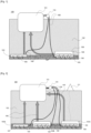
- FIG. 1 illustrates a diagram of the device 100 for cathodic protection against corrosion of a metal structure 101 in contact with an electrolytic medium 102 comprising a sedimentary soil 107 , according to an embodiment of the present invention, in which the cathodic protection device 100 further comprises two microbial anodic systems 103 arranged in contact with the electrolytic medium 102 and configured to provide electrons by biodegradation of oxidizable ambient resources (oxidation of chemical molecules), the free electrochemical potential of each microbial anodic system 103 being lower than the free electrochemical potential of the metal of the metal structure 101 to be protected.
- the cathodic protection device 100 further comprises two microbial anodic systems 103 arranged in contact with the electrolytic medium 102 and configured to provide electrons by biodegradation of oxidizable ambient resources (oxidation of chemical molecules), the free electrochemical potential of each microbial anodic system 103 being lower than the free electrochemical potential of the metal of the metal structure 101 to be protected.
- Each microbial anode system 103 comprises microorganisms. These microorganisms are at least those naturally present in the electrolytic medium 102 and can be supplemented by microorganisms provided for example in the form of a biofilm 104 of microorganisms as presented in figure 1 .
- Each microbial anode system 103 also comprises an electrode 105 which plays the role of anode in the cathodic protection device 100.
- the electrode 105 is buried at least partly in the sedimentary soil 107 of the natural electrolytic medium 102 so that the microorganisms included in the microbial anode system 103 are at least those of said soil 107.
- the metal structure 101 plays the role of cathode in the protection device 100.
- Each microbial anode system 103 is capable of generating electricity autonomously from oxidation reactions of ambient oxidizable resources (chemical molecules) carried out by the microorganisms it comprises. Indeed, said oxidation reactions result in the release and transfer of electrons to the electrode 105 that the microbial anode system 103 comprises, thus generating an electric current in the electrode 105.
- the sedimentary soil 107 of an electrolytic environment 102 (generally a natural electrolytic environment) is composed of microorganisms and sediments rich in oxidizable resources representing a target substrate for the biodegradation carried out by the microorganisms to create electricity.
- At least one of the microbial anode systems 103 comprises a chamber 106 comprising the biofilm 104 of microorganisms and the electrode 105.
- This chamber 106 is configured such that microorganisms present in the biofilm 104 of microorganisms are in contact with the electrolytic medium 102 and preferably with the sedimentary soil 107.
- Such a configuration corresponds for example to the fact that the chamber 106 is permeable to the electrolytic medium 102.
- the chamber 106 is also configured to receive resources oxidizable by the microorganisms of the microbial anode system 103.
- the cathodic protection device 100 further comprises a connecting means 108 between each microbial anode system 103 and the metal structure 101.
- This connecting means 108 is configured to allow the electrons to flow from said microbial anode system 103 to the metal structure 101.
- the connecting means 108 of course comprises an electron-conducting material, for example a metal.
- the connecting means 108 may for example be a cable comprising an electron-conducting core.
- a connecting means 108 between each microbial anode system 103 and the metal structure 101 is meant that either the cathodic protection device 100 comprises a single connecting means 108 connecting all the microbial anode systems and the metal structure 101 (not shown in the figures) or the cathodic protection device 100 comprises several connecting means 108, and for each connection between a microbial anode system 103 and the metal structure 101, a single distinct connecting means 108 is used (as shown in the figures).
- the connecting means 108 is in contact with the electrode 105.
- the electrons originating from the degradation by oxidation of the chemical molecules (oxidizable ambient resources) present in the electrolytic medium 102 and in particular the sediments which is carried out by the microorganisms of the microbial anode system 103 are transferred to the electrode 105.
- the electrons then pass from the electrode 105 to the connecting means 108 and circulate in said connecting means 108 to go into the metal structure 101.
- a protective galvanic current 109 is thus created through the electrolytic medium 102 between each microbial anodic system 103 and the metal structure 101.
- This galvanic current 109 advantageously protects the metal structure 101 against corrosion.
- the supply of a cathodic protection device by biogalvanic current can lead to the exhaustion of ambient oxidizable resources.
- An insufficient current would not allow protection of the structure against corrosion; conversely an excess of current can lead to an unnecessary exhaustion of the microbial resource.
- the present invention advantageously makes it possible to control the current delivered by one or a plurality of microbial anodic systems.
- the cathodic protection device 100 illustrated in figure 1 also comprises a control device 110 comprising a system for measuring the electron current flowing in the connecting means 108 or for measuring the electron current flowing in each connecting means and for determining the variations in the depletion of the oxidizable ambient resources, as well as a control system for stopping and activating the flow of the electron current flowing in the connecting means 108.
- a control device 110 comprising a system for measuring the electron current flowing in the connecting means 108 or for measuring the electron current flowing in each connecting means and for determining the variations in the depletion of the oxidizable ambient resources, as well as a control system for stopping and activating the flow of the electron current flowing in the connecting means 108.
- an operator of the cathodic protection device 100 will be able, using the measuring system, to advantageously measure the depolarization of the metal structure in order to evaluate the performance of the cathodic protection device within the meaning of standard EN ISO 12696.
- the exact number of microbial anode systems is calculated based on the regeneration kinetics of the oxidizable ambient resources.
- the control of the cathodic protection device (alternating operation between the microbial anode systems) is based on two elements which are compliance with the normative performance criteria (potential at cut-off current and depolarization) and compliance with a current criterion (predetermined threshold not to be exceeded) in anticipation of exhaustion of the oxidizable ambient resources (anticipation of non-compliance with the normative criteria).
- the cathodic protection device 100 comprises several microbial anode systems 103 in contact with the electrolytic medium 102, preferably at least three.
- a first microbial anode system 103A does not comprise a chamber 106 while a second microbial anode system microbial 103B and a third microbial anode system 103C comprise a chamber 106 comprising microorganisms preferably in the form of a biofilm 104 of microorganisms and an electrode 105.
- the cathodic protection device 100 comprises a connecting means 108 between each microbial anode system 103 and said metal structure 101, said connecting means 108 being configured to allow the electrons to flow from the electrode 105 of the microbial anode system 103 which it connects to the metal structure 101 to the latter.
- Each connecting means 108 is in contact with the electrode 105 of the microbial anode system 103 which it connects to the metal structure 101.
- a protective galvanic current 109 is thus created through the electrolytic medium 102 between each microbial anode system 103 and the metal structure 101.
- Each microbial anode system 103A, 103B, and 103C comprises an electrode 105 buried at least partly in the sedimentary soil 107 of the electrolytic medium 102 such that the microorganisms that the microbial anode systems 103 comprise are at least those of said electrolytic medium 102 and in particular those of the sediments of the soil 107.
- the third microbial anode system 103C is connected to a flotation device 111 configured to float in the electrolytic medium 102, preferably on the surface of the latter.
- a flotation device 111 may be, for example, a buoy.
- the cathodic protection device 100 illustrated in figure 2 also comprises a control apparatus 110 comprising a system for measuring the electron current flowing in each connecting means 108 or for measuring the electron current flowing in each connecting means and for determining variations in the depletion of the oxidizable ambient resources, as well as a control system for stopping and activating the flow of the electron current flowing in each connecting means 108.
- the operator of the device can measure the electron current flowing in each connecting means 108 and can also choose to stop or activate said electron current in each connecting means 108, which respectively stops or activates the galvanic current 109 of protection between the anode system 103 and the metal structure 101 connected by said connecting means 108 in which the current is stopped or activated.
- microorganisms present in the electrolytic medium 102 for example in the sedimentary soil 107, or the microorganisms brought by the user into a microbial anode system 103, during operation of the cathodic protection device 100 said microorganisms will gradually form a biofilm 104 of microorganisms on the surface of the electrode 105 which results in a progressive increase in the current flowing in the connecting means 108 connecting said electrode 105 to the metal structure 101 up to a peak value.
- This threshold value is for example a percentage reduction in the current flowing in the connecting means 108 evaluated relative to the peak value.
- the control system stops the flow of current in the connection means 108 concerned, thus allowing the stopping of the microbial anode system 103 to which it is linked and therefore the natural renewal of the oxidizable ambient resources which are in the environment close to the latter.
- the control system activates the flow of current in a connection means 108 connecting another microbial anode system 103 to the metal structure 101 so that the cathodic protection against corrosion of the latter continues.
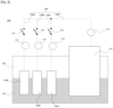
- FIG 3 illustrates a diagram of an embodiment of the cathodic protection device 100 which is the subject of the present invention.
- the protection device 100 comprises several microbial anode systems 103A, 103B and 103C buried at least partly in the sedimentary soil 107 of the electrolytic medium 102.
- the protection device 100 comprises a connecting means 108 comprising a main line 108P connected to the metal structure 101 and comprising a connection line 108A, 108B and 108C for each anode system, each connection line being connected to the main line 108P so that each microbial anode system 103 is connected to the metal structure 101.
- the system for measuring the electron current flowing in each connecting means 108 or for measuring the electron current flowing in each connecting means and for determining the variations in the depletion of the oxidizable ambient resources comprises an ammeter 114 arranged on each connection line 108A, 108B and 108C. It is thus possible to continuously measure the current flowing in each connection line 108A, 108B and 108C, which continuously indicates the current delivered by each microbial anode system 103 and makes it possible to determine the rate of exhaustion of the oxidizable ambient resources for each microbial anode system 103.
- the system for measuring the electron current flowing in each connection means 108 or for measuring the electron current flowing in each connection means and for determining the variations in exhaustion of the oxidizable ambient resources also comprises an ammeter 114 arranged on the main line 108P.
- the protection device 100 comprises a control system for stopping and activating the flow of the electron current flowing in the connecting means 108.
- the control system comprises a switch 115 arranged on each connection line 108A, 108B and 108C. It is thus possible to cut (interrupt the flow of current) and close (flow of current) the switches 115 so as to preserve the weakest microbial anode systems 103 whose oxidizable ambient resources are being exhausted and to allow them to regenerate by putting them to rest. This also makes it possible to regulate the current by activating or deactivating certain microbial anode systems 103 according to a predefined instruction in the interest of protecting the metal structure 101.
- the protection device 100 thus makes it possible to alternate the activation and deactivation of the microbial anode systems 103.
- the possibility is offered not only to preserve the microbial anode systems 103 and the ambient oxidizable resources of its close environment but also to regulate the current by quantum of a microbial anode system 103.
- control system may include, instead of the switches 115 or in addition to each switch 115, a variable resistor (not illustrated in the figures) thus making it possible to vary the intensity of the current reaching the metal structure 101 from each microbial anode system 103.
- the control system and the system for measuring the electron current flowing in each connecting means 108 or for measuring the electron current flowing in each connecting means and for determining the variations in the exhaustion of the oxidizable ambient resources can advantageously be automated and entrusted to a control device 110 such as a programmable automaton or an industrial computer.
- the switches 115 can be replaced by programmable relays and the ammeters 114 by analog-digital converters.
- the measuring system can in particular comprise a resistor placed in derivation (" shunt" in terminology English) on each connection line 108A, 108B and 108C so as to measure the current intensity in each of these connection lines.
- the cathodic protection obtained with the present invention was tested with a particular embodiment of the invention, given here for illustrative and non-limiting purposes.
- This is a cathodic protection device 100 according to the invention used for the protection of a metal structure 101 which is a reinforced concrete bridge pier in contact with an electrolytic medium 102, which is a marine environment, comprising sedimentary soil 107.
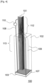
- This bridge pier is a concrete element 25 m high, with a section of 3x3 m 2 and reinforced with 76 longitudinal steel reinforcements of 32 mm in diameter ( figure 4 ).
- the metal structure 101 is immersed in sea water (electrolytic medium 102) to a depth of around 18 m and rests on a seabed (sedimentary soil 107) consisting of sediments rich in oxidizable resources for the microorganisms of the microbial anodic systems 103, only one of the latter being shown in the figure. figure 4 .
- the atmospheric concrete zone or emerged zone 112 is subject to the highest levels of damage, due to high contamination by chlorides, concrete partially saturated with water and a high availability of dioxygen. This zone constitutes the priority target of the cathodic protection device 100.
- the tidal zone 113 which is a partially submerged and partially emerged zone due to the difference in the water level depending on the tides, descends to a few meters below the water level (up to approximately 3 to 7 meters below the water level).
- the tidal zone 113 is also an area subject to high levels of damage. This vulnerability of the tidal zone is linked to the problem of the water/air interface with a high availability of oxygen, the reduction of which is involved in the corrosion phenomenon.
- the remainder of the metallic structure 101 immersed deeper is very little subject to corrosion due to the very low content or absence of oxygen in the electrolytic medium 102.
- One of the microbial anode systems 103 is positioned at the foot of the metal structure 101, at a depth of 18m, buried in the layer sedimentary and connected to the steel reinforcement network of the bridge pier by means of a connecting means 108 which here is an electric cable.
- the protective galvanic current lines 109 (in light gray) are observed on the figure 4 , exchanged naturally between the microbial anode system 103 and the steel reinforcement network of the reinforced concrete bridge pier. It is noted that, due to the absence of oxygen at depth, the galvanic current lines 109 rise vertically and enter the concrete near the water surface.
- FIG. 5 illustrates the distribution of the protective galvanic current 109 as a function of the height in the bridge pier.
- the protective current tends to concentrate in the oxygen-rich zones, which also correspond to the emerged zones 112 and the tidal zone 113, which are priorities for protection.
- the test was reproduced with various depths for the positioning of the microbial anode system 103, without significant impact on the quantity and distribution of the galvanic current 109 of protection towards the emerged zones 112 and tidal range 113 priority to be protected.
Landscapes
- Chemical & Material Sciences (AREA)
- Engineering & Computer Science (AREA)
- Materials Engineering (AREA)
- Mechanical Engineering (AREA)
- Metallurgy (AREA)
- Organic Chemistry (AREA)
- Prevention Of Electric Corrosion (AREA)
Claims (6)
- Gerät zum kathodischen Korrosionsschutz mindestens einer Metallstruktur in Kontakt mit einem elektrolytischen Medium, das einen sedimentären Boden umfasst, wobei das Schutzgerät kein Opfermetall und keine Verbindungsmittel zu einem elektrischen Verteilungsnetz umfasst, das Schutzgerät umfassend:- mindestens zwei mikrobielle Anodensysteme, die jeweils Mikroorganismen und eine Elektrode umfassen, die so konfiguriert ist, dass sie mit den Mikroorganismen und dem elektrolytischen Medium in Kontakt steht, wobei die Mikroorganismen die Fähigkeit aufweisen, durch Abbau oxidierbarer Umgebungsressourcen in Redoxreaktionen Elektronen an die Elektrode zu liefern, die Elektrode jedes mikrobiellen Anodensystems so konfiguriert ist, dass sie mindestens teilweise in dem sedimentären Boden des elektrolytischen Mediums vergraben ist, und das freie elektrochemische Potential jedes mikrobiellen Anodensystems niedriger ist als das freie elektrochemische Potential des Metalls der mindestens einen zu schützenden Metallstruktur;- mindestens ein Verbindungsmittel, das so konfiguriert ist, dass es jedes mikrobielle Anodensystem mit der mindestens einen Metallstruktur verbindet und so konfiguriert ist, dass es Elektronen von der Elektrode jedes mikrobielle Anodensystems zu der mindestens einen Metallstruktur fließen lässt;sodass ein galvanischer Schutzstrom durch das elektrolytische Medium von mindestens einem der mikrobiellen Anodensysteme zu der mindestens einen Metallstruktur fließt, wenn das mindestens eine mikrobielle Anodensystem in Kontakt mit dem elektrolytischen Medium ist und durch das mindestens eine Verbindungsmittel mit der mindestens einen Metallstruktur verbunden ist, wobei das Schutzgerät dadurch gekennzeichnet ist, dass es ferner Folgendes umfasst:∘ ein System zur Messung des Elektronenstroms, der durch jedes Verbindungsmittel fließt, wodurch die Schwankungen der Erschöpfung der oxidierbaren Umgebungsressourcen bekannt werden, die sich in der näheren Umgebung des mikrobiellen Anodensystems befinden, an das das Verbindungsmittel gebunden ist,∘ ein Kontrollsystem zum Anhalten und Aktivieren des Elektronenstroms, der durch jedes Verbindungsmittel fließt.
- Schutzgerät nach Anspruch 1, wobei die Mikroorganismen des mikrobiellen Anodensystems mindestens Mikroorganismen sind, die in dem elektrolytischen Medium vorhanden sind.
- Schutzgerät nach einem der Ansprüche 1 bis 2, wobei mindestens ein mikrobielles Anodensystem eine Kammer umfasst, die die Elektrode und die Mikroorganismen umfasst, wobei die Kammer so konfiguriert ist, dass sie oxidierbare Ressourcen aufnimmt, die durch die Mikroorganismen des mikrobiellen Anodensystems abbaubar sind.
- Schutzgerät nach einem der Ansprüche 1 bis 3, wobei der galvanische Schutzstrom in der Metallstruktur mit einer Dichte zwischen 0,2 mA/m2 und 100 mA/m2, vorzugsweise zwischen 0,2 mA/m2 und 20 mA/m2, verteilt wird.
- Schutzgerät nach einem der Ansprüche 1 bis 4, wobei mindestens ein mikrobielles Anodensystem mit einem Flotationsgerät verbunden ist, das auf der Oberfläche des elektrolytischen Mediums schwimmt.
- Verfahren zum kathodischen Schutz gegen Korrosion von mindestens einer Metallstruktur in Kontakt mit einem elektrolytischen Medium unter Verwendung des kathodischen Schutzgeräts nach einem der Ansprüche 1 bis 5 und umfassend die folgenden Schritte:- Einrichten von mehreren mikrobiellen Anodensystemen bestehend aus Mikroorganismen und eine Elektrode, die mit den Mikroorganismen und dem elektrolytischen Medium in Kontakt steht, wobei das mikrobielle Anodensystem so konfiguriert ist, dass es durch den Abbau oxidierbarer Umgebungsressourcen durch die Mikroorganismen Elektronen an die Elektrode liefert, wobei die Elektrode jedes mikrobielle Anodensystems mindestens teilweise in dem sedimentären Boden des elektrolytischen Mediums vergraben ist und das freie elektrochemische Potential des mikrobielle Anodensystems niedriger ist als das freie elektrochemische Potential des Metalls der mindestens einen zu schützenden Metallstruktur;- Verbinden der mindestens einen Metallstruktur mit jedem mikrobiellen Anodensystem mit mindestens einem Verbindungsmittel, das so konfiguriert ist, dass es Elektronen von der Elektrode jedes mikrobiellen Anodensystems zu der mindestens einen Metallstruktur fließen lässt;- zeitlich alternierendes Aktivieren des Elektronenflusses zwischen jeder Elektrode des bakteriellen Anodensystems und der mindestens einen Metallstruktur, umfassend die Teilschritte:∘ Aktivieren des Elektronenflusses in mindestens einem Verbindungsmittel, das mindestens ein mikrobielles Anodensystem mit der Metallstruktur verbindet, sodass ein schützender galvanischer Strom durch das elektrolytische Medium von dem mindestens einen mikrobiellen Anodensystem zu der mindestens einen Metallstruktur fließt;∘ Anhalten des Elektronenflusses in dem mindestens einen Verbindungsmittel, das mindestens ein mikrobielles Anodensystem mit der Metallstruktur verbindet, wenn ein vorbestimmter Schwellenwert der Verarmung an Elektronen, die in dem mindestens einen Verbindungsmittel fließen, erreicht wird, wobei der vorbestimmte Schwellenwert einen Schwellenwert der Verarmung an oxidierbaren Umgebungsressourcen in der nahen Umgebung des mindestens einen mikrobiellen Anodensystems belegt, und Aktivieren des Elektronenflusses in mindestens einem Verbindungsmittel, das mindestens ein weiteres mikrobielles Anodensystem mit der Metallstruktur verbindet.
Applications Claiming Priority (1)
| Application Number | Priority Date | Filing Date | Title |
|---|---|---|---|
| FR2106008A FR3123662A1 (fr) | 2021-06-08 | 2021-06-08 | Dispositif de protection cathodique d’une structure métallique contre la corrosion |
Publications (4)
| Publication Number | Publication Date |
|---|---|
| EP4101944A2 EP4101944A2 (de) | 2022-12-14 |
| EP4101944A3 EP4101944A3 (de) | 2023-04-05 |
| EP4101944C0 EP4101944C0 (de) | 2024-08-28 |
| EP4101944B1 true EP4101944B1 (de) | 2024-08-28 |
Family
ID=78536261
Family Applications (1)
| Application Number | Title | Priority Date | Filing Date |
|---|---|---|---|
| EP22177625.5A Active EP4101944B1 (de) | 2021-06-08 | 2022-06-07 | Vorrichtung zum kathodischen schutz einer metallstruktur gegen korrosion |
Country Status (3)
| Country | Link |
|---|---|
| EP (1) | EP4101944B1 (de) |
| ES (1) | ES2997432T3 (de) |
| FR (1) | FR3123662A1 (de) |
Family Cites Families (6)
| Publication number | Priority date | Publication date | Assignee | Title |
|---|---|---|---|---|
| EP2500512B1 (de) * | 2011-03-17 | 2014-02-26 | Vetco Gray Inc. | Austauschbare Kathodenschutzanode |
| JP6071053B2 (ja) * | 2013-03-07 | 2017-02-01 | 鹿島建設株式会社 | 構造物金属材の電気防食方法及び装置 |
| US20150259806A1 (en) * | 2014-03-15 | 2015-09-17 | Nicolas de Pierola | Detached Retrievable Outboard System and Apparatus for Sacrificial Anodes. |
| WO2018122126A1 (en) * | 2016-12-27 | 2018-07-05 | Koninklijke Philips N.V. | Arrangement for anti-fouling of a protected surface |
| CN110257832A (zh) * | 2019-06-28 | 2019-09-20 | 西华大学 | 一种生物电化学装置 |
| CN111534822B (zh) * | 2020-05-11 | 2022-04-26 | 中国船舶科学研究中心 | 一种基于生物阳极的深海装备阴极保护装置 |
-
2021
- 2021-06-08 FR FR2106008A patent/FR3123662A1/fr active Pending
-
2022
- 2022-06-07 ES ES22177625T patent/ES2997432T3/es active Active
- 2022-06-07 EP EP22177625.5A patent/EP4101944B1/de active Active
Also Published As
| Publication number | Publication date |
|---|---|
| ES2997432T3 (en) | 2025-02-17 |
| EP4101944C0 (de) | 2024-08-28 |
| FR3123662A1 (fr) | 2022-12-09 |
| EP4101944A3 (de) | 2023-04-05 |
| EP4101944A2 (de) | 2022-12-14 |
Similar Documents
| Publication | Publication Date | Title |
|---|---|---|
| Hasvold et al. | Sea-water battery for subsea control systems | |
| Guerrini et al. | Electrochemical behavior of stainless steel anodes in membraneless microbial fuel cells | |
| CN110114955B (zh) | 用于外加电流阴极保护的系统 | |
| US20150198518A1 (en) | Cathodic protection reference cell article and method | |
| CA2504882C (fr) | Structure et revetement auto-reparables pour milieu corrosif | |
| Kim et al. | Enhanced power performance of an in situ sediment microbial fuel cell with steel-slag as the redox catalyst: I. electricity generation | |
| JP2019508875A (ja) | 負荷設備及び負荷に電力供給するための電力設備 | |
| EP2888201B1 (de) | Chemische stabilisierung von graphitoberflächen | |
| Linhardt | Unusual corrosion of nickel‐aluminium bronze in a hydroelectric power plant | |
| EP4101944A2 (de) | Vorrichtung zum kathodischen schutz einer metallstruktur gegen korrosion | |
| KR20110122797A (ko) | 연안용 강 구조물을 위한 부식 방지 장치 및 그 제조 방법 | |
| Salaün et al. | Beyond the hydrogen wave: new frontier in the detection of trace elements by stripping voltammetry | |
| JP6071053B2 (ja) | 構造物金属材の電気防食方法及び装置 | |
| US20250188619A1 (en) | Dispositif de protection cathodique d'un structure métallique contre la corrosion | |
| WO2013113777A1 (fr) | Dispositif de protection cathodique d'une paroi métallique contre la corrosion dans un milieu salin | |
| FR2904330A1 (fr) | Dispositif d'electrolyse de l'eau et son utilisation pour produire de l'hydrogene | |
| JP2009197292A (ja) | 水中に設けられた鋼構造物の防食装置 | |
| Larsen | Retrofitting Wind Turbine Monopiles with Cathodic ProtectionStrategy Developed to Protect Submerged Internal Spaces with Aluminum Anodes | |
| JP5678505B2 (ja) | 有潮流海域での海洋鋼構造物の防食被膜形成方法 | |
| WO2015108525A1 (en) | Cathodic protection reference cell article and method | |
| JP7299467B2 (ja) | 水素発生装置 | |
| WO2021111314A1 (fr) | Anode de protection cathodique pour structure en mer et dispositif de protection cathodique la comprenant | |
| JP6422122B2 (ja) | 底質改善方法及び底質改善装置 | |
| WO2013104725A1 (fr) | Pile à combustible microbienne avec cathode facilement échangeable | |
| JP3386898B2 (ja) | 被防食材の防食構造 |
Legal Events
| Date | Code | Title | Description |
|---|---|---|---|
| PUAI | Public reference made under article 153(3) epc to a published international application that has entered the european phase |
Free format text: ORIGINAL CODE: 0009012 |
|
| STAA | Information on the status of an ep patent application or granted ep patent |
Free format text: STATUS: THE APPLICATION HAS BEEN PUBLISHED |
|
| AK | Designated contracting states |
Kind code of ref document: A2 Designated state(s): AL AT BE BG CH CY CZ DE DK EE ES FI FR GB GR HR HU IE IS IT LI LT LU LV MC MK MT NL NO PL PT RO RS SE SI SK SM TR |
|
| PUAL | Search report despatched |
Free format text: ORIGINAL CODE: 0009013 |
|
| AK | Designated contracting states |
Kind code of ref document: A3 Designated state(s): AL AT BE BG CH CY CZ DE DK EE ES FI FR GB GR HR HU IE IS IT LI LT LU LV MC MK MT NL NO PL PT RO RS SE SI SK SM TR |
|
| RIC1 | Information provided on ipc code assigned before grant |
Ipc: C02F 1/46 20060101ALI20230228BHEP Ipc: C23F 13/06 20060101ALI20230228BHEP Ipc: C23F 13/02 20060101AFI20230228BHEP |
|
| STAA | Information on the status of an ep patent application or granted ep patent |
Free format text: STATUS: REQUEST FOR EXAMINATION WAS MADE |
|
| 17P | Request for examination filed |
Effective date: 20231002 |
|
| RBV | Designated contracting states (corrected) |
Designated state(s): AL AT BE BG CH CY CZ DE DK EE ES FI FR GB GR HR HU IE IS IT LI LT LU LV MC MK MT NL NO PL PT RO RS SE SI SK SM TR |
|
| GRAP | Despatch of communication of intention to grant a patent |
Free format text: ORIGINAL CODE: EPIDOSNIGR1 |
|
| STAA | Information on the status of an ep patent application or granted ep patent |
Free format text: STATUS: GRANT OF PATENT IS INTENDED |
|
| INTG | Intention to grant announced |
Effective date: 20240403 |
|
| GRAS | Grant fee paid |
Free format text: ORIGINAL CODE: EPIDOSNIGR3 |
|
| GRAA | (expected) grant |
Free format text: ORIGINAL CODE: 0009210 |
|
| STAA | Information on the status of an ep patent application or granted ep patent |
Free format text: STATUS: THE PATENT HAS BEEN GRANTED |
|
| AK | Designated contracting states |
Kind code of ref document: B1 Designated state(s): AL AT BE BG CH CY CZ DE DK EE ES FI FR GB GR HR HU IE IS IT LI LT LU LV MC MK MT NL NO PL PT RO RS SE SI SK SM TR |
|
| REG | Reference to a national code |
Ref country code: CH Ref legal event code: EP |
|
| REG | Reference to a national code |
Ref country code: DE Ref legal event code: R096 Ref document number: 602022005606 Country of ref document: DE |
|
| REG | Reference to a national code |
Ref country code: IE Ref legal event code: FG4D Free format text: LANGUAGE OF EP DOCUMENT: FRENCH |
|
| U01 | Request for unitary effect filed |
Effective date: 20240917 |
|
| U07 | Unitary effect registered |
Designated state(s): AT BE BG DE DK EE FI FR IT LT LU LV MT NL PT RO SE SI Effective date: 20241010 |
|
| PG25 | Lapsed in a contracting state [announced via postgrant information from national office to epo] |
Ref country code: PL Free format text: LAPSE BECAUSE OF FAILURE TO SUBMIT A TRANSLATION OF THE DESCRIPTION OR TO PAY THE FEE WITHIN THE PRESCRIBED TIME-LIMIT Effective date: 20240828 Ref country code: GR Free format text: LAPSE BECAUSE OF FAILURE TO SUBMIT A TRANSLATION OF THE DESCRIPTION OR TO PAY THE FEE WITHIN THE PRESCRIBED TIME-LIMIT Effective date: 20241129 |
|
| PG25 | Lapsed in a contracting state [announced via postgrant information from national office to epo] |
Ref country code: IS Free format text: LAPSE BECAUSE OF FAILURE TO SUBMIT A TRANSLATION OF THE DESCRIPTION OR TO PAY THE FEE WITHIN THE PRESCRIBED TIME-LIMIT Effective date: 20241228 |
|
| PG25 | Lapsed in a contracting state [announced via postgrant information from national office to epo] |
Ref country code: HR Free format text: LAPSE BECAUSE OF FAILURE TO SUBMIT A TRANSLATION OF THE DESCRIPTION OR TO PAY THE FEE WITHIN THE PRESCRIBED TIME-LIMIT Effective date: 20240828 |
|
| PG25 | Lapsed in a contracting state [announced via postgrant information from national office to epo] |
Ref country code: RS Free format text: LAPSE BECAUSE OF FAILURE TO SUBMIT A TRANSLATION OF THE DESCRIPTION OR TO PAY THE FEE WITHIN THE PRESCRIBED TIME-LIMIT Effective date: 20241128 |
|
| PG25 | Lapsed in a contracting state [announced via postgrant information from national office to epo] |
Ref country code: RS Free format text: LAPSE BECAUSE OF FAILURE TO SUBMIT A TRANSLATION OF THE DESCRIPTION OR TO PAY THE FEE WITHIN THE PRESCRIBED TIME-LIMIT Effective date: 20241128 Ref country code: PL Free format text: LAPSE BECAUSE OF FAILURE TO SUBMIT A TRANSLATION OF THE DESCRIPTION OR TO PAY THE FEE WITHIN THE PRESCRIBED TIME-LIMIT Effective date: 20240828 Ref country code: IS Free format text: LAPSE BECAUSE OF FAILURE TO SUBMIT A TRANSLATION OF THE DESCRIPTION OR TO PAY THE FEE WITHIN THE PRESCRIBED TIME-LIMIT Effective date: 20241228 Ref country code: HR Free format text: LAPSE BECAUSE OF FAILURE TO SUBMIT A TRANSLATION OF THE DESCRIPTION OR TO PAY THE FEE WITHIN THE PRESCRIBED TIME-LIMIT Effective date: 20240828 Ref country code: GR Free format text: LAPSE BECAUSE OF FAILURE TO SUBMIT A TRANSLATION OF THE DESCRIPTION OR TO PAY THE FEE WITHIN THE PRESCRIBED TIME-LIMIT Effective date: 20241129 |
|
| REG | Reference to a national code |
Ref country code: ES Ref legal event code: FG2A Ref document number: 2997432 Country of ref document: ES Kind code of ref document: T3 Effective date: 20250217 |
|
| PG25 | Lapsed in a contracting state [announced via postgrant information from national office to epo] |
Ref country code: SM Free format text: LAPSE BECAUSE OF FAILURE TO SUBMIT A TRANSLATION OF THE DESCRIPTION OR TO PAY THE FEE WITHIN THE PRESCRIBED TIME-LIMIT Effective date: 20240828 |
|
| PG25 | Lapsed in a contracting state [announced via postgrant information from national office to epo] |
Ref country code: CZ Free format text: LAPSE BECAUSE OF FAILURE TO SUBMIT A TRANSLATION OF THE DESCRIPTION OR TO PAY THE FEE WITHIN THE PRESCRIBED TIME-LIMIT Effective date: 20240828 |
|
| PG25 | Lapsed in a contracting state [announced via postgrant information from national office to epo] |
Ref country code: SK Free format text: LAPSE BECAUSE OF FAILURE TO SUBMIT A TRANSLATION OF THE DESCRIPTION OR TO PAY THE FEE WITHIN THE PRESCRIBED TIME-LIMIT Effective date: 20240828 |
|
| PLBE | No opposition filed within time limit |
Free format text: ORIGINAL CODE: 0009261 |
|
| STAA | Information on the status of an ep patent application or granted ep patent |
Free format text: STATUS: NO OPPOSITION FILED WITHIN TIME LIMIT |
|
| PGFP | Annual fee paid to national office [announced via postgrant information from national office to epo] |
Ref country code: NO Payment date: 20250627 Year of fee payment: 4 |
|
| U20 | Renewal fee for the european patent with unitary effect paid |
Year of fee payment: 4 Effective date: 20250619 |
|
| 26N | No opposition filed |
Effective date: 20250530 |
|
| PGFP | Annual fee paid to national office [announced via postgrant information from national office to epo] |
Ref country code: ES Payment date: 20250707 Year of fee payment: 4 |
|
| PGFP | Annual fee paid to national office [announced via postgrant information from national office to epo] |
Ref country code: CH Payment date: 20250711 Year of fee payment: 4 |
|
| U1N | Appointed representative for the unitary patent procedure changed after the registration of the unitary effect |
Representative=s name: SANTARELLI; FR |
|
| PG25 | Lapsed in a contracting state [announced via postgrant information from national office to epo] |
Ref country code: MC Free format text: LAPSE BECAUSE OF FAILURE TO SUBMIT A TRANSLATION OF THE DESCRIPTION OR TO PAY THE FEE WITHIN THE PRESCRIBED TIME-LIMIT Effective date: 20240828 |
|
| PG25 | Lapsed in a contracting state [announced via postgrant information from national office to epo] |
Ref country code: IE Free format text: LAPSE BECAUSE OF NON-PAYMENT OF DUE FEES Effective date: 20250607 |