EP4101722B1 - Fahrzeug zur personenbeförderung mit einer variablen anzahl von sitzplätzen - Google Patents
Fahrzeug zur personenbeförderung mit einer variablen anzahl von sitzplätzen Download PDFInfo
- Publication number
- EP4101722B1 EP4101722B1 EP22177862.4A EP22177862A EP4101722B1 EP 4101722 B1 EP4101722 B1 EP 4101722B1 EP 22177862 A EP22177862 A EP 22177862A EP 4101722 B1 EP4101722 B1 EP 4101722B1
- Authority
- EP
- European Patent Office
- Prior art keywords
- longitudinal bar
- vehicle
- movable part
- support structure
- une
- Prior art date
- Legal status (The legal status is an assumption and is not a legal conclusion. Google has not performed a legal analysis and makes no representation as to the accuracy of the status listed.)
- Active
Links
Images







Classifications
-
- B—PERFORMING OPERATIONS; TRANSPORTING
- B60—VEHICLES IN GENERAL
- B60N—SEATS SPECIALLY ADAPTED FOR VEHICLES; VEHICLE PASSENGER ACCOMMODATION NOT OTHERWISE PROVIDED FOR
- B60N2/00—Seats specially adapted for vehicles; Arrangement or mounting of seats in vehicles
- B60N2/24—Seats specially adapted for vehicles; Arrangement or mounting of seats in vehicles for particular purposes or particular vehicles
- B60N2/30—Non-dismountable or dismountable seats storable in a non-use position, e.g. foldable spare seats
-
- B—PERFORMING OPERATIONS; TRANSPORTING
- B60—VEHICLES IN GENERAL
- B60N—SEATS SPECIALLY ADAPTED FOR VEHICLES; VEHICLE PASSENGER ACCOMMODATION NOT OTHERWISE PROVIDED FOR
- B60N2/00—Seats specially adapted for vehicles; Arrangement or mounting of seats in vehicles
- B60N2/24—Seats specially adapted for vehicles; Arrangement or mounting of seats in vehicles for particular purposes or particular vehicles
- B60N2/242—Bus seats
-
- B—PERFORMING OPERATIONS; TRANSPORTING
- B60—VEHICLES IN GENERAL
- B60N—SEATS SPECIALLY ADAPTED FOR VEHICLES; VEHICLE PASSENGER ACCOMMODATION NOT OTHERWISE PROVIDED FOR
- B60N2/00—Seats specially adapted for vehicles; Arrangement or mounting of seats in vehicles
- B60N2/24—Seats specially adapted for vehicles; Arrangement or mounting of seats in vehicles for particular purposes or particular vehicles
- B60N2/30—Non-dismountable or dismountable seats storable in a non-use position, e.g. foldable spare seats
- B60N2/3038—Cushion movements
- B60N2/3063—Cushion movements by composed movement
- B60N2/3065—Cushion movements by composed movement in a longitudinal-vertical plane
-
- B—PERFORMING OPERATIONS; TRANSPORTING
- B61—RAILWAYS
- B61D—BODY DETAILS OR KINDS OF RAILWAY VEHICLES
- B61D33/00—Seats
- B61D33/0007—Details; Accessories
-
- B—PERFORMING OPERATIONS; TRANSPORTING
- B61—RAILWAYS
- B61D—BODY DETAILS OR KINDS OF RAILWAY VEHICLES
- B61D33/00—Seats
- B61D33/0057—Seats characterised by their mounting in vehicles
- B61D33/0078—Seats characterised by their mounting in vehicles adjustably mounted
-
- B—PERFORMING OPERATIONS; TRANSPORTING
- B64—AIRCRAFT; AVIATION; COSMONAUTICS
- B64D—EQUIPMENT FOR FITTING IN OR TO AIRCRAFT; FLIGHT SUITS; PARACHUTES; ARRANGEMENT OR MOUNTING OF POWER PLANTS OR PROPULSION TRANSMISSIONS IN AIRCRAFT
- B64D11/00—Passenger or crew accommodation; Flight-deck installations not otherwise provided for
- B64D11/06—Arrangements of seats, or adaptations or details specially adapted for aircraft seats
- B64D11/0691—Arrangements of seats, or adaptations or details specially adapted for aircraft seats specially adapted for cabin crew
-
- B—PERFORMING OPERATIONS; TRANSPORTING
- B60—VEHICLES IN GENERAL
- B60N—SEATS SPECIALLY ADAPTED FOR VEHICLES; VEHICLE PASSENGER ACCOMMODATION NOT OTHERWISE PROVIDED FOR
- B60N2/00—Seats specially adapted for vehicles; Arrangement or mounting of seats in vehicles
- B60N2/24—Seats specially adapted for vehicles; Arrangement or mounting of seats in vehicles for particular purposes or particular vehicles
- B60N2002/247—Seats specially adapted for vehicles; Arrangement or mounting of seats in vehicles for particular purposes or particular vehicles to support passengers in a half-standing position
Definitions
- the present invention relates in general to a passenger transport vehicle, and in particular to a passenger transport vehicle equipped with a space management system inside the vehicle which makes it possible to adapt the space available between the passengers. seated and standing passengers depending on the actual service conditions, and especially the density or quantity of passengers transported during the different times of the service.
- the vehicles or convoys used are very congested for at least some part of their service, and especially during peak hours.
- the number of seats available and their positioning is generally predefined and during peak hours most passengers must therefore remain standing; on the other hand, during off-peak hours, it is also possible for passengers to remain standing, even if there is plenty of space available inside the vehicle.
- a main aim of the present invention is to provide a solution offering improvements compared to the known state of the art, and especially to produce passenger transport vehicles where the exploitation of space at the
- the interior of the vehicle can be optimized according to different operating conditions during the operating time, in particular according to passenger traffic.
- each of the terms indicated above includes electronic circuits, as well as software codes and/or algorithms or complete programs stored or being executed.
- transverse or transversely when used herein, they should be understood to encompass a possible variation of plus or minus 5% from an indicated reference value or position; furthermore, when the terms transverse or transversely are used herein, they shall be understood as encompassing a direction not parallel to the part(s) or direction(s)/reference axis to which they refer, and perpendicularity shall be taken as a specific case of transverse direction.
- FIG. 1 schematically illustrates the interior of a passenger transport vehicle according to the present invention, designated with the reference number 1.
- the definition of "passenger transport vehicle” used herein should be interpreted in the broadest possible sense, c i.e. as including any type of passenger transport vehicle, and this definition can therefore be taken to also cover railway vehicles, for example trams, surface trains, and the like.
- the vehicle 1 comprises a space management system inside the vehicle 1, which is configured to modify the configuration of this space intended to accommodate passengers, and in particular to modify the number of seats available depending on the effective density of passengers to be transported, i.e. the level of passenger traffic to be transported.
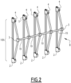
- the management system used comprises at least one support structure, indicated generally with the reference number 100 on the figures 1 And 2 , having a fixed part 106 and a movable part 105 which is movable, relative to the fixed part 106, between a first position, indicated on the figure 1 by the letter A, in which the movable part 105 is deployed vis-à-vis the fixed part 106 so that the mechanical support structure 100 generally forms at least one seating place available for passengers, and a second position, indicated on the figure 2 by the letter B, in which the movable part 105 is retracted towards the fixed part 106 so that the at least one place seat is unavailable for the seat by increasing the space available inside the vehicle for standing passengers.
- the mechanical support structure 100 is configured to form at least one ischial support for the passengers when the movable part 105 is in the second position.
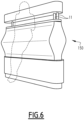
- the mechanical support structure 100 comprises at least one covering surface, indicated on the Figure 6 by the reference 150 which is connected to and is arranged around at least one portion of the movable part 105.
- the covering surface 150 and the movable part 105 are substantially integral with each other and move together when the movable part 105 is moved relative to the fixed part 106.
- the or each covering surface 150 comprises at least a first substantially rigid portion 152 forming a seated surface when the movable part 105 is in the first position A.
- the covering surface 150 comprises a second substantially rigid portion 153, and a third deformable portion 154 which is arranged between the first and second substantially rigid portions 152 and 153 and which is connected to the first substantially rigid portion 152 and to the second portion substantially rigid 153 so that the first and second substantially rigid portions form with the third deformable portion 154 an ischial support surface when the movable part 105 is in the second position B.
- the mechanical support structure 100 comprises an additional covering surface, indicated by the reference 155, which is separated from the rigid portion 152 forming a seated surface when the movable part 105 is in the first position A.
- the surface of additional covering 155 is connected to at least two fifth longitudinal bars 16, and is configured to form at least one backrest for the passengers.
- longitudinal must be understood here as indicating a body having a dimension measured in one direction, for example for the first bar 11 along its longitudinal axis indicated on the figure 1 by the reference number 110, significantly larger than the other two dimensions.
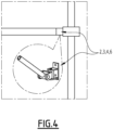
- each first connection means 3 comprises an articulation, an example of a possible embodiment of which is illustrated in the figure 4 .
- this articulation is positioned between and is connected to the second end 32 of the corresponding second longitudinal bar 12 and to the second end 23 of the corresponding third longitudinal bar 13, and allows rotation around the axis of the articulation of each third longitudinal bar 13 relative to each corresponding second longitudinal bar 12.
- the mechanical support structure 100 comprises second connection means 2 configured to connect the second end 22 of the or each second longitudinal bar 12 to the first end 21 of the or each corresponding first longitudinal bar 11.
- each second connection means 2 comprises a joint, an example of a possible embodiment of which is illustrated on the figure 4 , which is connected to the second end 22 of the corresponding second longitudinal bar 12 and to the first end 21 of the corresponding first longitudinal bar 11.
- the mechanical support structure 100 further comprises third connection means 4 configured to connect the second end 33 of the or each third longitudinal bar 13 to the or each corresponding first longitudinal bar 11, in a manner mobile relative to each other.
- each third connection means 4 comprises an articulation, an example of a possible embodiment of which is also illustrated on the figure 4 , which is connected to the second end 33 of the corresponding third longitudinal bar 13 and to the corresponding first longitudinal bar 11.
- the mechanical support structure 100 further comprises at least a fourth longitudinal bar 19 configured to connect two first connection means 3 placed one after the other along the transverse axis 10.
- the mechanical support structure 100 comprises a plurality of fourth longitudinal bars 19, each fourth longitudinal bar 19 being configured to connect two first connection means 3 placed one after the other along along the transverse axis 10.
- the fixed part 106 of the support structure 100 comprises at least the first longitudinal bar(s) 11 which are installed in the vehicle 1 at a distance from one another along the transverse axis 10, for example in a substantially vertical position, and which have for example the shape of a track.
- the movable part 106 comprises at least the second longitudinal bar(s) 12, the third longitudinal bar(s) 13, the fourth longitudinal bar(s) 19, and the connection means 2, 3, 4
- the mechanical support structure 100 further comprises at least a fifth longitudinal bar 16 and fourth connection means 6 which are configured to connect a first end 26 of the fifth longitudinal bar 6 to the first bar longitudinal bar 11, near the second end 31 of this first longitudinal bar 11.
- the mechanical support structure 100 comprises a plurality of fifth longitudinal bars 16, that is to say at least two longitudinal bars 16, and a plurality of fourth connection means 6 which are configured to connect a first end 26 of each fifth longitudinal bar 6 to a first corresponding longitudinal bar 11, near the second end 31 of this corresponding first longitudinal bar 11.
- a free space 37 is formed between the or each fifth longitudinal bar 16 and the or each first longitudinal bar 11 to accommodate at least a portion of the movable part 105 when the movable part 105 is in the second position B.
- the fourth connection means 6 are configured to allow rotation of each fifth longitudinal bar 16 around the transverse axis 10 relative to the corresponding first longitudinal bar 11.
- each fourth connection means 6 comprises an articulation connected to the first end 26 of the corresponding fifth longitudinal bar 16 and to the corresponding first longitudinal bar 11.
- An example of realization of each means of connection is illustrated on the Figure 4 .
- each fifth longitudinal bar 16 is connected to a first corresponding longitudinal bar 11, its second end 36 being free and suspended in the air. Furthermore, at least one additional covering surface 155 is disposed on and is connected to at least two of the fifth longitudinal bars 16, and is configured to form at least one backrest for the passengers.
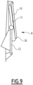
- each fifth longitudinal bar 16 is arranged so that its second end 36 is provided to rest on a body of the corresponding third longitudinal bar 13 when the movable part 105 is in the first position A, and is provided to slide on the body of and relative to the third longitudinal bar 13 corresponding when the movable part 105 is moved between the first position A and the second position B, as illustrated by the positions illustrated in sequence in Figures 7 to 9.
- an additional covering surface 155 is also disposed on and is connected to at least two of the fifth longitudinal bars 16, and is configured to form at least one backrest for the passengers, as illustrated on the Figure 10 where the movable part of the structure 100 is in the first position A forming seats, and in the Figure 11 where structure 100 is in the second position B.
- the space management system comprises at least one control device 200, represented schematically on the figures 1 , 3 And 7 in the form of a box drawn in dotted lines, which is configured to generate at least one remote control signal S c adapted to activate the modification of the number of seats available for passengers, and in particular to activate, preferably substantially in real time, the movement of the mobile part 105 relative to the fixed part 106.
- control device 200 is configured to generate the control signal S c remotely relative to the position of the seats to be modified, that is to say far from the seats, and in particular where the passengers cannot activate it.
- control device 200 is installed on board the vehicle 1, for example in the cockpit or the cockpit of the vehicle 1, or in any position inaccessible to passengers, and is configured to activate the modification of the number of seats available to passengers, substantially in real time during the movement of the vehicle 1, in particular according to the actual conditions of passenger traffic.
- an operator on board vehicle 1 can activate the modification of the number of seats available for passengers on the basis of his direct view or according to images provided by video cameras.
- video cameras can be mounted, for example, in the space intended to accommodate passengers and/or on station platforms, and can monitor the effective density of passengers to be transported.
- the management system used in the vehicle 1 comprises actuation means represented schematically on the figures 1 , 3 And 7 in the form of a box with dotted lines 5, which are configured to move the or each movable part 105 between the first position A and the second position B, depending on the control signal S c received and which was emitted by the device order 200.
- the actuation means 5 comprise at least one motor controlled remotely by the control device 200.
- the or each remotely controlled motor is a linear motor which is mounted on a first longitudinal bar 11 and which slides, along the body of this first longitudinal bar 11, moving in a manner substantially integral with the corresponding third longitudinal bar 13 and the second longitudinal bar 12.
- the actuation means 5 comprise several remotely controlled motors, in particular two or more linear motors, each motor being mounted on a first corresponding longitudinal bar 11 and sliding, along the body of this first corresponding longitudinal bar 11, in moving substantially integrally with the third longitudinal bar 13 and the second longitudinal bar 12 associated with this first longitudinal bar 11.
- the passenger transport vehicle 1 makes it possible to achieve the aim underlying the present invention because the space available inside the vehicle can be managed more efficiently compared to the solutions known.
- the space inside the vehicle is used in an optimized manner either during off-peak hours or during peak service hours.
- the internal configuration of the vehicle can be adapted to traffic in real time: when passenger traffic is fluid, the number of available seats is increased; on the contrary, when the traffic is denser, these seats, individual or grouped for example in the form of benches, are retracted, freeing up all the bulk space so as to allow the greatest number of passengers to have space standing. In this configuration, the capacity gain is optimal.
- the movable covering surfaces which form the available seating places and/or the ischial support may have the form of a sliding bench comprising a plurality of seats or seats, placed side by side, as illustrated in the figures 5 to 6 And 10 to 11 , or they can form individual seats or ischial supports. It is possible to create a combination with seats or seats in the form of benches or similar, and individual seats or seats.
- the movable seats can be positioned along the central corridor of the vehicle 1 and/or along the sides; the control device 200 can be configured to selectively move a certain number of movable seats and not all at the same time; the bars used may have a different shape compared to the shapes illustrated in the figures; the connection position, for example of each second longitudinal bar 12 along the body of a corresponding first longitudinal bar 11, may be different; each fifth longitudinal bar 16 can be connected to a first longitudinal bar 11 in a fixed manner.
Landscapes
- Engineering & Computer Science (AREA)
- Mechanical Engineering (AREA)
- Aviation & Aerospace Engineering (AREA)
- Transportation (AREA)
- Seats For Vehicles (AREA)
- Fittings On The Vehicle Exterior For Carrying Loads, And Devices For Holding Or Mounting Articles (AREA)
Claims (8)
- Fahrzeug (1) zur Beförderung von Passagieren mit einem System zur Verwaltung des Raums im Inneren des Fahrzeugs, das derart ausgelegt ist, dass es die Anzahl der verfügbaren Sitzplätze in Abhängigkeit vom Verkehrsaufkommen der zu befördernden Passagiere variiert, wobei das Verwaltungssystem mindestens eine mechanische Stützstruktur (100) mit einem festen Teil (106) und einem beweglichen Teil (105) aufweist, der in Bezug auf den festen Teil (106) zwischen einer ersten Position (A), in der der bewegliche Teil gegenüber dem festen Teil derart ausgeklappt ist, dass die die mechanische Stützstruktur (100) mindestens einen Sitzplatz bildet, der den Passagieren zu Verfügung steht, und einer zweiten Position (B), in der der bewegliche Teil zum festen Teil derart eingeklappt ist, dass der mindestens eine Sitzplatz nicht zum Sitzen zur Verfügung steht, bewegbar ist, dadurch gekennzeichnet, dass die mechanische Stützstruktur (100) mindestens eine Verkleidungsfläche (150) aufweist, die mit mindestens einem Abschnitt des beweglichen Teils (105) verbunden und um diesen herum angeordnet ist, wobei sich die Verkleidungsfläche (150) und der bewegliche Teil (105) gemeinsam bewegen, indem sie substantiell fest miteinander verbunden sind, und wobei die mindestens eine Verkleidungsfläche (150) mindestens einen ersten substantiell starren Abschnitt (152), einen zweiten substantiell starren Abschnitt (153) und einen dritten verformbaren Abschnitt (154) aufweist, der zwischen dem ersten und dem zweiten substantiell starren Abschnitt angeordnet und der mit dem ersten substantiell starren Abschnitt (152) und mit dem zweiten substantiell starren Abschnitt (153) verbunden ist, wobei der erste substantiell starre Abschnitt (152) eine Sitzfläche bildet, wenn der bewegliche Teil (105) in der ersten Position (A) ist, während der erste und der zweite substantiell starre Abschnitt (152, 153) gemeinsam mit dem verformbaren dritten Abschnitt (154) eine ischiatische Stützfläche bilden, wenn der bewegliche Teil (105) in der zweiten Position (B) ist.
- Fahrzeug (1) nach Anspruch 1, wobei die mechanische Stützstruktur (100) dazu ausgelegt ist, dass sie mindestens eine ischiatische Stütze für die Passagiere bildet, wenn der bewegliche Teil (105) in der zweiten Position ist.
- Fahrzeug (1) nach einem oder mehreren der Ansprüche 1 bis 2, wobei die mechanische Stützstruktur (100) mindestens umfasst:- eine erste Längsstange (11), die im Inneren des Fahrzeugs (1) fest installiert ist;- eine zweite Längsstange (12) mit einem ersten Ende (22), das mit der ersten Längsstange (11) in der Nähe eines ersten Endes (21) der ersten Längsstange (11) verbunden ist; und- eine dritte Längsstange (13) mit einem ersten Ende (33), das mit der ersten Längsstange (11) gleitend verbunden ist; und- erste Verbindungsmittel (3), die dazu ausgelegt sind, dass sie ein zweites Ende (32) der zweiten Längsstange (12) mit einem zweiten Ende (23) der dritten Längsstange (13) im Verhältnis zueinander beweglich verbinden.
- Fahrzeug (1) nach Anspruch 3, wobei die mechanische Stützstruktur (100) zweite Verbindungsmittel (2) aufweist, die dazu ausgelegt sind, dass sie das zweite Ende (22) der oder jeder zweiten Längsstange (12) mit der oder jeder entsprechenden ersten Längsstange (11) verbinden, so dass dieses zweite Ende (22) entlang der entsprechenden ersten Längsstange (11) fest ist, während die oder jede zweite Längsstange (12) im Verhältnis zu der entsprechenden ersten Längsstange (11) kippen kann.
- Fahrzeug (1) nach einem oder mehreren der Ansprüche 1 bis 4, wobei das Verwaltungssystem ferner eine Steuervorrichtung (200) umfasst, die an Bord des Fahrzeugs (1) installiert und dazu ausgelegt ist, mindestens ein Fernsteuersignal (Sc) bereitzustellen, um die Bewegung des beweglichen Teils (105) im Verhältnis zum festen Teil (106) vorzugsweise substantiell in Echtzeit zu aktivieren.
- Fahrzeug (1) nach Anspruch 5, wobei das Verwaltungssystem Betätigungsmittel (5) umfasst, die dazu ausgelegt sind, den mindestens einen beweglichen Teil (105) in Abhängigkeit von einem Steuersignal (Sc), das von der Steuervorrichtung (200) ferngesteuert gesendet wird, zwischen der ersten Position (A) und der zweiten Position (B) zu bewegen.
- Fahrzeug (1) nach Anspruch 6, wobei die Betätigungsmittel (5) mindestens einen ferngesteuerten Motor umfassen.
- Fahrzeug (1) nach Anspruch 6 oder 7 in Kombination mit Anspruch 3, wobei der mindestens eine ferngesteuerte Motor ein Linearmotor ist, der auf der ersten Längsstange (11) gleitend angebracht ist, indem er mit der entsprechenden dritten Längsstange (13) substantiell fest verbunden ist.
Applications Claiming Priority (1)
| Application Number | Priority Date | Filing Date | Title |
|---|---|---|---|
| FR2106065A FR3123835B1 (fr) | 2021-06-09 | 2021-06-09 | Véhicule de transport de passagers avec nombre de places assises variable |
Publications (2)
| Publication Number | Publication Date |
|---|---|
| EP4101722A1 EP4101722A1 (de) | 2022-12-14 |
| EP4101722B1 true EP4101722B1 (de) | 2023-11-08 |
Family
ID=76730868
Family Applications (1)
| Application Number | Title | Priority Date | Filing Date |
|---|---|---|---|
| EP22177862.4A Active EP4101722B1 (de) | 2021-06-09 | 2022-06-08 | Fahrzeug zur personenbeförderung mit einer variablen anzahl von sitzplätzen |
Country Status (5)
| Country | Link |
|---|---|
| US (1) | US11912177B2 (de) |
| EP (1) | EP4101722B1 (de) |
| BR (1) | BR102022011210A2 (de) |
| ES (1) | ES2970758T3 (de) |
| FR (1) | FR3123835B1 (de) |
Families Citing this family (2)
| Publication number | Priority date | Publication date | Assignee | Title |
|---|---|---|---|---|
| FR3098458B1 (fr) * | 2019-07-08 | 2021-07-23 | Alstom Transp Tech | Dispositif d’accueil de passagers et véhicule de transport en commun associé |
| US11958387B2 (en) * | 2021-05-27 | 2024-04-16 | International Truck Intellectual Property Company, Llc | Seating in a vehicle |
Family Cites Families (12)
| Publication number | Priority date | Publication date | Assignee | Title |
|---|---|---|---|---|
| US1170343A (en) * | 1912-12-27 | 1916-02-01 | Nat Pneumatic Co | Disappearing and reversible seat for cars. |
| US1412367A (en) * | 1920-11-04 | 1922-04-11 | Murphy Door Bed Company | Disappearing structure |
| US3011826A (en) * | 1960-01-06 | 1961-12-05 | John I R Bowring | Lightweight crew seat for high performance flight vehicles |
| DE102007042489A1 (de) * | 2007-09-06 | 2009-03-12 | Grammer Ag | Fahrzeugsitz mit Beinauflage |
| CN201183490Y (zh) * | 2008-02-01 | 2009-01-21 | 上海市闵行中学 | 一种地铁车厢内的座椅结构 |
| US8827365B2 (en) * | 2010-02-10 | 2014-09-09 | Zodiac Seats Us Llc | Passenger seat |
| GB2561344B (en) * | 2017-04-03 | 2020-02-26 | Tangerine Ltd | Occupant Support Device For a Seat |
| CN209870614U (zh) * | 2019-01-10 | 2019-12-31 | 文余 | 电动车的变形式坐垫结构 |
| US11472559B1 (en) * | 2019-03-29 | 2022-10-18 | B/E Aerospace, Inc. | Coil hinge for aircraft seat |
| CN110356296A (zh) * | 2019-07-25 | 2019-10-22 | 北京洪泰智造信息技术有限公司 | 一种可折叠座椅、其控制方法和系统 |
| CN112824205A (zh) * | 2019-11-21 | 2021-05-21 | 中车唐山机车车辆有限公司 | 一种电动折叠座椅控制方法及装置 |
| US20220072978A1 (en) * | 2020-09-04 | 2022-03-10 | Faurecia Automotive Seating, Llc | Multi-position vehicle seat |
-
2021
- 2021-06-09 FR FR2106065A patent/FR3123835B1/fr active Active
-
2022
- 2022-06-07 US US17/805,838 patent/US11912177B2/en active Active
- 2022-06-08 EP EP22177862.4A patent/EP4101722B1/de active Active
- 2022-06-08 ES ES22177862T patent/ES2970758T3/es active Active
- 2022-06-08 BR BR102022011210-0A patent/BR102022011210A2/pt unknown
Also Published As
| Publication number | Publication date |
|---|---|
| BR102022011210A2 (pt) | 2023-01-24 |
| FR3123835A1 (fr) | 2022-12-16 |
| US20220396185A1 (en) | 2022-12-15 |
| EP4101722A1 (de) | 2022-12-14 |
| FR3123835B1 (fr) | 2025-05-09 |
| US11912177B2 (en) | 2024-02-27 |
| ES2970758T3 (es) | 2024-05-30 |
Similar Documents
| Publication | Publication Date | Title |
|---|---|---|
| EP4101722B1 (de) | Fahrzeug zur personenbeförderung mit einer variablen anzahl von sitzplätzen | |
| EP3601050B1 (de) | Anordnung aus einzelnen sitzen für passagiere eines flugzeugs | |
| FR3100012A1 (fr) | Siège de véhicule à assise inclinable pour faciliter l’accès aux places arrière | |
| FR3051739A1 (fr) | Agencement de sieges pour vehicule automobile | |
| EP4101688B1 (de) | Fahrzeug zur personenbeförderung mit variabler anzahl von sitzplätzen und verfahren zur handhabung des verfügbaren raums im inneren des fahrzeugs | |
| FR3074107A1 (fr) | Siege automobile rotatif comprenant un organe anti-arrachement et vehicule automobile comprenant un tel siege | |
| EP3590759A1 (de) | Passagiersitz in einem transportfahrzeug und mit solchen sitzen ausgestattetes transportfahrzeug | |
| EP4051589B1 (de) | Sitz, insbesondere für ein flugzeug, mit einer einzigen betätigungsvorrichtung | |
| EP3028916B1 (de) | Durchgangsvorrichtung für gelenkfahrzeug für den öffentlichen verkehr, insbesondere ein schienenfahrzeug | |
| FR3119805A1 (fr) | Siège de véhicule | |
| EP3778336B1 (de) | Fahrzeugsitz mit verbessertem stauraum und entsprechendes fahrzeug | |
| EP3904157B1 (de) | Sitz für fahrzeug, der ein rückhaltesystem für die einstell- und aufhängungsvorrichtung umfasst | |
| FR2890911A1 (fr) | Vehicule automobile equipe de deux sieges lateraux mobiles transversalement et longitudinalement au vehicule et procede de transformation des sieges d'un tel vehicule | |
| FR3039469A1 (fr) | Banquette pour vehicule de transport comprenant un siege d'appoint | |
| EP4049890A1 (de) | Sitz mit armlehne(n) und entsprechendes transportfahrzeug | |
| FR3150502A1 (fr) | Accoudoir partagé pour un siège multiplace | |
| FR2861341A1 (fr) | Vehicule automobile a moyens de liaison a un siege et a une console, ensemble comprenant un siege, une console et des moyens de liaison au plancher d'un tel vehicule, et utilisation d'un siege a la place d'une console | |
| WO2024251947A1 (fr) | Arrangement d'unités de siéges et cabine d'avion comportant un tel arrangement d'unités de siéges | |
| EP2868519A1 (de) | Versenkbarer Sitz mit Kippsicherung | |
| FR3164664A1 (fr) | Agencement de sièges dans un véhicule automobile doté de deux rangées de trois sièges | |
| WO2026078316A1 (fr) | Véhicule équipé d'une fixation de siège avant compatible avec une banquette deux places | |
| FR3141397A1 (fr) | Siège de véhicule automobile à dossier réversible | |
| FR2850064A1 (fr) | Ensemble de console comprenant une console mobile et des moyens de blocage de la console et vehicule automobile correspondant | |
| FR2829081A1 (fr) | Console centrale modulaire de vehicule automobile, et vehicule automobile equipe d'une telle console | |
| FR3100170A1 (fr) | Ensemble de sièges comprenant un siège central modulable |
Legal Events
| Date | Code | Title | Description |
|---|---|---|---|
| PUAI | Public reference made under article 153(3) epc to a published international application that has entered the european phase |
Free format text: ORIGINAL CODE: 0009012 |
|
| STAA | Information on the status of an ep patent application or granted ep patent |
Free format text: STATUS: THE APPLICATION HAS BEEN PUBLISHED |
|
| STAA | Information on the status of an ep patent application or granted ep patent |
Free format text: STATUS: REQUEST FOR EXAMINATION WAS MADE |
|
| AK | Designated contracting states |
Kind code of ref document: A1 Designated state(s): AL AT BE BG CH CY CZ DE DK EE ES FI FR GB GR HR HU IE IS IT LI LT LU LV MC MK MT NL NO PL PT RO RS SE SI SK SM TR |
|
| 17P | Request for examination filed |
Effective date: 20221124 |
|
| RBV | Designated contracting states (corrected) |
Designated state(s): AL AT BE BG CH CY CZ DE DK EE ES FI FR GB GR HR HU IE IS IT LI LT LU LV MC MK MT NL NO PL PT RO RS SE SI SK SM TR |
|
| GRAP | Despatch of communication of intention to grant a patent |
Free format text: ORIGINAL CODE: EPIDOSNIGR1 |
|
| STAA | Information on the status of an ep patent application or granted ep patent |
Free format text: STATUS: GRANT OF PATENT IS INTENDED |
|
| INTG | Intention to grant announced |
Effective date: 20230609 |
|
| P01 | Opt-out of the competence of the unified patent court (upc) registered |
Effective date: 20230822 |
|
| GRAS | Grant fee paid |
Free format text: ORIGINAL CODE: EPIDOSNIGR3 |
|
| GRAA | (expected) grant |
Free format text: ORIGINAL CODE: 0009210 |
|
| STAA | Information on the status of an ep patent application or granted ep patent |
Free format text: STATUS: THE PATENT HAS BEEN GRANTED |
|
| AK | Designated contracting states |
Kind code of ref document: B1 Designated state(s): AL AT BE BG CH CY CZ DE DK EE ES FI FR GB GR HR HU IE IS IT LI LT LU LV MC MK MT NL NO PL PT RO RS SE SI SK SM TR |
|
| REG | Reference to a national code |
Ref country code: GB Ref legal event code: FG4D Free format text: NOT ENGLISH |
|
| REG | Reference to a national code |
Ref country code: CH Ref legal event code: EP |
|
| REG | Reference to a national code |
Ref country code: DE Ref legal event code: R096 Ref document number: 602022000923 Country of ref document: DE |
|
| REG | Reference to a national code |
Ref country code: IE Ref legal event code: FG4D Free format text: LANGUAGE OF EP DOCUMENT: FRENCH |
|
| REG | Reference to a national code |
Ref country code: LT Ref legal event code: MG9D |
|
| REG | Reference to a national code |
Ref country code: NL Ref legal event code: MP Effective date: 20231108 |
|
| PG25 | Lapsed in a contracting state [announced via postgrant information from national office to epo] |
Ref country code: GR Free format text: LAPSE BECAUSE OF FAILURE TO SUBMIT A TRANSLATION OF THE DESCRIPTION OR TO PAY THE FEE WITHIN THE PRESCRIBED TIME-LIMIT Effective date: 20240209 |
|
| PG25 | Lapsed in a contracting state [announced via postgrant information from national office to epo] |
Ref country code: IS Free format text: LAPSE BECAUSE OF FAILURE TO SUBMIT A TRANSLATION OF THE DESCRIPTION OR TO PAY THE FEE WITHIN THE PRESCRIBED TIME-LIMIT Effective date: 20240308 |
|
| PG25 | Lapsed in a contracting state [announced via postgrant information from national office to epo] |
Ref country code: LT Free format text: LAPSE BECAUSE OF FAILURE TO SUBMIT A TRANSLATION OF THE DESCRIPTION OR TO PAY THE FEE WITHIN THE PRESCRIBED TIME-LIMIT Effective date: 20231108 |
|
| REG | Reference to a national code |
Ref country code: AT Ref legal event code: MK05 Ref document number: 1629373 Country of ref document: AT Kind code of ref document: T Effective date: 20231108 |
|
| PG25 | Lapsed in a contracting state [announced via postgrant information from national office to epo] |
Ref country code: NL Free format text: LAPSE BECAUSE OF FAILURE TO SUBMIT A TRANSLATION OF THE DESCRIPTION OR TO PAY THE FEE WITHIN THE PRESCRIBED TIME-LIMIT Effective date: 20231108 |
|
| PG25 | Lapsed in a contracting state [announced via postgrant information from national office to epo] |
Ref country code: AT Free format text: LAPSE BECAUSE OF FAILURE TO SUBMIT A TRANSLATION OF THE DESCRIPTION OR TO PAY THE FEE WITHIN THE PRESCRIBED TIME-LIMIT Effective date: 20231108 |
|
| PG25 | Lapsed in a contracting state [announced via postgrant information from national office to epo] |
Ref country code: NL Free format text: LAPSE BECAUSE OF FAILURE TO SUBMIT A TRANSLATION OF THE DESCRIPTION OR TO PAY THE FEE WITHIN THE PRESCRIBED TIME-LIMIT Effective date: 20231108 Ref country code: LT Free format text: LAPSE BECAUSE OF FAILURE TO SUBMIT A TRANSLATION OF THE DESCRIPTION OR TO PAY THE FEE WITHIN THE PRESCRIBED TIME-LIMIT Effective date: 20231108 Ref country code: IS Free format text: LAPSE BECAUSE OF FAILURE TO SUBMIT A TRANSLATION OF THE DESCRIPTION OR TO PAY THE FEE WITHIN THE PRESCRIBED TIME-LIMIT Effective date: 20240308 Ref country code: GR Free format text: LAPSE BECAUSE OF FAILURE TO SUBMIT A TRANSLATION OF THE DESCRIPTION OR TO PAY THE FEE WITHIN THE PRESCRIBED TIME-LIMIT Effective date: 20240209 Ref country code: BG Free format text: LAPSE BECAUSE OF FAILURE TO SUBMIT A TRANSLATION OF THE DESCRIPTION OR TO PAY THE FEE WITHIN THE PRESCRIBED TIME-LIMIT Effective date: 20240208 Ref country code: AT Free format text: LAPSE BECAUSE OF FAILURE TO SUBMIT A TRANSLATION OF THE DESCRIPTION OR TO PAY THE FEE WITHIN THE PRESCRIBED TIME-LIMIT Effective date: 20231108 Ref country code: PT Free format text: LAPSE BECAUSE OF FAILURE TO SUBMIT A TRANSLATION OF THE DESCRIPTION OR TO PAY THE FEE WITHIN THE PRESCRIBED TIME-LIMIT Effective date: 20240308 |
|
| REG | Reference to a national code |
Ref country code: ES Ref legal event code: FG2A Ref document number: 2970758 Country of ref document: ES Kind code of ref document: T3 Effective date: 20240530 |
|
| PG25 | Lapsed in a contracting state [announced via postgrant information from national office to epo] |
Ref country code: SE Free format text: LAPSE BECAUSE OF FAILURE TO SUBMIT A TRANSLATION OF THE DESCRIPTION OR TO PAY THE FEE WITHIN THE PRESCRIBED TIME-LIMIT Effective date: 20231108 Ref country code: RS Free format text: LAPSE BECAUSE OF FAILURE TO SUBMIT A TRANSLATION OF THE DESCRIPTION OR TO PAY THE FEE WITHIN THE PRESCRIBED TIME-LIMIT Effective date: 20231108 Ref country code: PL Free format text: LAPSE BECAUSE OF FAILURE TO SUBMIT A TRANSLATION OF THE DESCRIPTION OR TO PAY THE FEE WITHIN THE PRESCRIBED TIME-LIMIT Effective date: 20231108 Ref country code: NO Free format text: LAPSE BECAUSE OF FAILURE TO SUBMIT A TRANSLATION OF THE DESCRIPTION OR TO PAY THE FEE WITHIN THE PRESCRIBED TIME-LIMIT Effective date: 20240208 Ref country code: LV Free format text: LAPSE BECAUSE OF FAILURE TO SUBMIT A TRANSLATION OF THE DESCRIPTION OR TO PAY THE FEE WITHIN THE PRESCRIBED TIME-LIMIT Effective date: 20231108 Ref country code: HR Free format text: LAPSE BECAUSE OF FAILURE TO SUBMIT A TRANSLATION OF THE DESCRIPTION OR TO PAY THE FEE WITHIN THE PRESCRIBED TIME-LIMIT Effective date: 20231108 |
|
| PG25 | Lapsed in a contracting state [announced via postgrant information from national office to epo] |
Ref country code: DK Free format text: LAPSE BECAUSE OF FAILURE TO SUBMIT A TRANSLATION OF THE DESCRIPTION OR TO PAY THE FEE WITHIN THE PRESCRIBED TIME-LIMIT Effective date: 20231108 |
|
| PG25 | Lapsed in a contracting state [announced via postgrant information from national office to epo] |
Ref country code: CZ Free format text: LAPSE BECAUSE OF FAILURE TO SUBMIT A TRANSLATION OF THE DESCRIPTION OR TO PAY THE FEE WITHIN THE PRESCRIBED TIME-LIMIT Effective date: 20231108 |
|
| PG25 | Lapsed in a contracting state [announced via postgrant information from national office to epo] |
Ref country code: SK Free format text: LAPSE BECAUSE OF FAILURE TO SUBMIT A TRANSLATION OF THE DESCRIPTION OR TO PAY THE FEE WITHIN THE PRESCRIBED TIME-LIMIT Effective date: 20231108 |
|
| PG25 | Lapsed in a contracting state [announced via postgrant information from national office to epo] |
Ref country code: SM Free format text: LAPSE BECAUSE OF FAILURE TO SUBMIT A TRANSLATION OF THE DESCRIPTION OR TO PAY THE FEE WITHIN THE PRESCRIBED TIME-LIMIT Effective date: 20231108 Ref country code: SK Free format text: LAPSE BECAUSE OF FAILURE TO SUBMIT A TRANSLATION OF THE DESCRIPTION OR TO PAY THE FEE WITHIN THE PRESCRIBED TIME-LIMIT Effective date: 20231108 Ref country code: RO Free format text: LAPSE BECAUSE OF FAILURE TO SUBMIT A TRANSLATION OF THE DESCRIPTION OR TO PAY THE FEE WITHIN THE PRESCRIBED TIME-LIMIT Effective date: 20231108 Ref country code: EE Free format text: LAPSE BECAUSE OF FAILURE TO SUBMIT A TRANSLATION OF THE DESCRIPTION OR TO PAY THE FEE WITHIN THE PRESCRIBED TIME-LIMIT Effective date: 20231108 Ref country code: DK Free format text: LAPSE BECAUSE OF FAILURE TO SUBMIT A TRANSLATION OF THE DESCRIPTION OR TO PAY THE FEE WITHIN THE PRESCRIBED TIME-LIMIT Effective date: 20231108 Ref country code: CZ Free format text: LAPSE BECAUSE OF FAILURE TO SUBMIT A TRANSLATION OF THE DESCRIPTION OR TO PAY THE FEE WITHIN THE PRESCRIBED TIME-LIMIT Effective date: 20231108 |
|
| REG | Reference to a national code |
Ref country code: DE Ref legal event code: R097 Ref document number: 602022000923 Country of ref document: DE |
|
| PLBE | No opposition filed within time limit |
Free format text: ORIGINAL CODE: 0009261 |
|
| STAA | Information on the status of an ep patent application or granted ep patent |
Free format text: STATUS: NO OPPOSITION FILED WITHIN TIME LIMIT |
|
| 26N | No opposition filed |
Effective date: 20240809 |
|
| PG25 | Lapsed in a contracting state [announced via postgrant information from national office to epo] |
Ref country code: SI Free format text: LAPSE BECAUSE OF FAILURE TO SUBMIT A TRANSLATION OF THE DESCRIPTION OR TO PAY THE FEE WITHIN THE PRESCRIBED TIME-LIMIT Effective date: 20231108 |
|
| PG25 | Lapsed in a contracting state [announced via postgrant information from national office to epo] |
Ref country code: SI Free format text: LAPSE BECAUSE OF FAILURE TO SUBMIT A TRANSLATION OF THE DESCRIPTION OR TO PAY THE FEE WITHIN THE PRESCRIBED TIME-LIMIT Effective date: 20231108 |
|
| PG25 | Lapsed in a contracting state [announced via postgrant information from national office to epo] |
Ref country code: MC Free format text: LAPSE BECAUSE OF FAILURE TO SUBMIT A TRANSLATION OF THE DESCRIPTION OR TO PAY THE FEE WITHIN THE PRESCRIBED TIME-LIMIT Effective date: 20231108 |
|
| PG25 | Lapsed in a contracting state [announced via postgrant information from national office to epo] |
Ref country code: LU Free format text: LAPSE BECAUSE OF NON-PAYMENT OF DUE FEES Effective date: 20240608 |
|
| PG25 | Lapsed in a contracting state [announced via postgrant information from national office to epo] |
Ref country code: IE Free format text: LAPSE BECAUSE OF NON-PAYMENT OF DUE FEES Effective date: 20240608 |
|
| PG25 | Lapsed in a contracting state [announced via postgrant information from national office to epo] |
Ref country code: BE Free format text: LAPSE BECAUSE OF NON-PAYMENT OF DUE FEES Effective date: 20240630 |
|
| REG | Reference to a national code |
Ref country code: BE Ref legal event code: MM Effective date: 20240630 |
|
| PGFP | Annual fee paid to national office [announced via postgrant information from national office to epo] |
Ref country code: DE Payment date: 20250618 Year of fee payment: 4 |
|
| PGFP | Annual fee paid to national office [announced via postgrant information from national office to epo] |
Ref country code: FR Payment date: 20250627 Year of fee payment: 4 |
|
| PG25 | Lapsed in a contracting state [announced via postgrant information from national office to epo] |
Ref country code: FI Free format text: LAPSE BECAUSE OF FAILURE TO SUBMIT A TRANSLATION OF THE DESCRIPTION OR TO PAY THE FEE WITHIN THE PRESCRIBED TIME-LIMIT Effective date: 20231108 |
|
| PGFP | Annual fee paid to national office [announced via postgrant information from national office to epo] |
Ref country code: ES Payment date: 20250731 Year of fee payment: 4 |
|
| PGFP | Annual fee paid to national office [announced via postgrant information from national office to epo] |
Ref country code: IT Payment date: 20250630 Year of fee payment: 4 |
|
| PG25 | Lapsed in a contracting state [announced via postgrant information from national office to epo] |
Ref country code: CY Free format text: LAPSE BECAUSE OF FAILURE TO SUBMIT A TRANSLATION OF THE DESCRIPTION OR TO PAY THE FEE WITHIN THE PRESCRIBED TIME-LIMIT; INVALID AB INITIO Effective date: 20220608 |
|
| REG | Reference to a national code |
Ref country code: CH Ref legal event code: H13 Free format text: ST27 STATUS EVENT CODE: U-0-0-H10-H13 (AS PROVIDED BY THE NATIONAL OFFICE) Effective date: 20260127 |
|
| PG25 | Lapsed in a contracting state [announced via postgrant information from national office to epo] |
Ref country code: HU Free format text: LAPSE BECAUSE OF FAILURE TO SUBMIT A TRANSLATION OF THE DESCRIPTION OR TO PAY THE FEE WITHIN THE PRESCRIBED TIME-LIMIT; INVALID AB INITIO Effective date: 20220608 |
|
| PG25 | Lapsed in a contracting state [announced via postgrant information from national office to epo] |
Ref country code: CH Free format text: LAPSE BECAUSE OF NON-PAYMENT OF DUE FEES Effective date: 20250630 |