EP4101676B1 - Überwachungssystem für fahrzeuge - Google Patents
Überwachungssystem für fahrzeuge Download PDFInfo
- Publication number
- EP4101676B1 EP4101676B1 EP21178559.7A EP21178559A EP4101676B1 EP 4101676 B1 EP4101676 B1 EP 4101676B1 EP 21178559 A EP21178559 A EP 21178559A EP 4101676 B1 EP4101676 B1 EP 4101676B1
- Authority
- EP
- European Patent Office
- Prior art keywords
- sub
- energy consumption
- vehicle
- energy
- display unit
- Prior art date
- Legal status (The legal status is an assumption and is not a legal conclusion. Google has not performed a legal analysis and makes no representation as to the accuracy of the status listed.)
- Active
Links
Images
Classifications
-
- B—PERFORMING OPERATIONS; TRANSPORTING
- B60—VEHICLES IN GENERAL
- B60W—CONJOINT CONTROL OF VEHICLE SUB-UNITS OF DIFFERENT TYPE OR DIFFERENT FUNCTION; CONTROL SYSTEMS SPECIALLY ADAPTED FOR HYBRID VEHICLES; ROAD VEHICLE DRIVE CONTROL SYSTEMS FOR PURPOSES NOT RELATED TO THE CONTROL OF A PARTICULAR SUB-UNIT
- B60W50/00—Details of control systems for road vehicle drive control not related to the control of a particular sub-unit, e.g. process diagnostic or vehicle driver interfaces
- B60W50/08—Interaction between the driver and the control system
- B60W50/14—Means for informing the driver, warning the driver or prompting a driver intervention
-
- B—PERFORMING OPERATIONS; TRANSPORTING
- B60—VEHICLES IN GENERAL
- B60K—ARRANGEMENT OR MOUNTING OF PROPULSION UNITS OR OF TRANSMISSIONS IN VEHICLES; ARRANGEMENT OR MOUNTING OF PLURAL DIVERSE PRIME-MOVERS IN VEHICLES; AUXILIARY DRIVES FOR VEHICLES; INSTRUMENTATION OR DASHBOARDS FOR VEHICLES; ARRANGEMENTS IN CONNECTION WITH COOLING, AIR INTAKE, GAS EXHAUST OR FUEL SUPPLY OF PROPULSION UNITS IN VEHICLES
- B60K35/00—Instruments specially adapted for vehicles; Arrangement of instruments in or on vehicles
- B60K35/10—Input arrangements, i.e. from user to vehicle, associated with vehicle functions or specially adapted therefor
-
- B—PERFORMING OPERATIONS; TRANSPORTING
- B60—VEHICLES IN GENERAL
- B60K—ARRANGEMENT OR MOUNTING OF PROPULSION UNITS OR OF TRANSMISSIONS IN VEHICLES; ARRANGEMENT OR MOUNTING OF PLURAL DIVERSE PRIME-MOVERS IN VEHICLES; AUXILIARY DRIVES FOR VEHICLES; INSTRUMENTATION OR DASHBOARDS FOR VEHICLES; ARRANGEMENTS IN CONNECTION WITH COOLING, AIR INTAKE, GAS EXHAUST OR FUEL SUPPLY OF PROPULSION UNITS IN VEHICLES
- B60K35/00—Instruments specially adapted for vehicles; Arrangement of instruments in or on vehicles
- B60K35/20—Output arrangements, i.e. from vehicle to user, associated with vehicle functions or specially adapted therefor
- B60K35/21—Output arrangements, i.e. from vehicle to user, associated with vehicle functions or specially adapted therefor using visual output, e.g. blinking lights or matrix displays
- B60K35/22—Display screens
-
- B—PERFORMING OPERATIONS; TRANSPORTING
- B60—VEHICLES IN GENERAL
- B60K—ARRANGEMENT OR MOUNTING OF PROPULSION UNITS OR OF TRANSMISSIONS IN VEHICLES; ARRANGEMENT OR MOUNTING OF PLURAL DIVERSE PRIME-MOVERS IN VEHICLES; AUXILIARY DRIVES FOR VEHICLES; INSTRUMENTATION OR DASHBOARDS FOR VEHICLES; ARRANGEMENTS IN CONNECTION WITH COOLING, AIR INTAKE, GAS EXHAUST OR FUEL SUPPLY OF PROPULSION UNITS IN VEHICLES
- B60K35/00—Instruments specially adapted for vehicles; Arrangement of instruments in or on vehicles
- B60K35/20—Output arrangements, i.e. from vehicle to user, associated with vehicle functions or specially adapted therefor
- B60K35/28—Output arrangements, i.e. from vehicle to user, associated with vehicle functions or specially adapted therefor characterised by the type of the output information, e.g. video entertainment or vehicle dynamics information; characterised by the purpose of the output information, e.g. for attracting the attention of the driver
-
- B—PERFORMING OPERATIONS; TRANSPORTING
- B60—VEHICLES IN GENERAL
- B60K—ARRANGEMENT OR MOUNTING OF PROPULSION UNITS OR OF TRANSMISSIONS IN VEHICLES; ARRANGEMENT OR MOUNTING OF PLURAL DIVERSE PRIME-MOVERS IN VEHICLES; AUXILIARY DRIVES FOR VEHICLES; INSTRUMENTATION OR DASHBOARDS FOR VEHICLES; ARRANGEMENTS IN CONNECTION WITH COOLING, AIR INTAKE, GAS EXHAUST OR FUEL SUPPLY OF PROPULSION UNITS IN VEHICLES
- B60K35/00—Instruments specially adapted for vehicles; Arrangement of instruments in or on vehicles
- B60K35/20—Output arrangements, i.e. from vehicle to user, associated with vehicle functions or specially adapted therefor
- B60K35/29—Instruments characterised by the way in which information is handled, e.g. showing information on plural displays or prioritising information according to driving conditions
-
- B—PERFORMING OPERATIONS; TRANSPORTING
- B60—VEHICLES IN GENERAL
- B60L—PROPULSION OF ELECTRICALLY-PROPELLED VEHICLES; SUPPLYING ELECTRIC POWER FOR AUXILIARY EQUIPMENT OF ELECTRICALLY-PROPELLED VEHICLES; ELECTRODYNAMIC BRAKE SYSTEMS FOR VEHICLES IN GENERAL; MAGNETIC SUSPENSION OR LEVITATION FOR VEHICLES; MONITORING OPERATING VARIABLES OF ELECTRICALLY-PROPELLED VEHICLES; ELECTRIC SAFETY DEVICES FOR ELECTRICALLY-PROPELLED VEHICLES
- B60L58/00—Methods or circuit arrangements for monitoring or controlling batteries or fuel cells, specially adapted for electric vehicles
- B60L58/10—Methods or circuit arrangements for monitoring or controlling batteries or fuel cells, specially adapted for electric vehicles for monitoring or controlling batteries
- B60L58/12—Methods or circuit arrangements for monitoring or controlling batteries or fuel cells, specially adapted for electric vehicles for monitoring or controlling batteries responding to state of charge [SoC]
- B60L58/13—Maintaining the SoC within a determined range
-
- B—PERFORMING OPERATIONS; TRANSPORTING
- B60—VEHICLES IN GENERAL
- B60R—VEHICLES, VEHICLE FITTINGS, OR VEHICLE PARTS, NOT OTHERWISE PROVIDED FOR
- B60R16/00—Electric or fluid circuits specially adapted for vehicles and not otherwise provided for; Arrangement of elements of electric or fluid circuits specially adapted for vehicles and not otherwise provided for
- B60R16/02—Electric or fluid circuits specially adapted for vehicles and not otherwise provided for; Arrangement of elements of electric or fluid circuits specially adapted for vehicles and not otherwise provided for electric constitutive elements
- B60R16/03—Electric or fluid circuits specially adapted for vehicles and not otherwise provided for; Arrangement of elements of electric or fluid circuits specially adapted for vehicles and not otherwise provided for electric constitutive elements for supply of electrical power to vehicle subsystems or for
-
- B—PERFORMING OPERATIONS; TRANSPORTING
- B60—VEHICLES IN GENERAL
- B60K—ARRANGEMENT OR MOUNTING OF PROPULSION UNITS OR OF TRANSMISSIONS IN VEHICLES; ARRANGEMENT OR MOUNTING OF PLURAL DIVERSE PRIME-MOVERS IN VEHICLES; AUXILIARY DRIVES FOR VEHICLES; INSTRUMENTATION OR DASHBOARDS FOR VEHICLES; ARRANGEMENTS IN CONNECTION WITH COOLING, AIR INTAKE, GAS EXHAUST OR FUEL SUPPLY OF PROPULSION UNITS IN VEHICLES
- B60K2360/00—Indexing scheme associated with groups B60K35/00 or B60K37/00 relating to details of instruments or dashboards
- B60K2360/11—Instrument graphical user interfaces or menu aspects
- B60K2360/119—Icons
-
- B—PERFORMING OPERATIONS; TRANSPORTING
- B60—VEHICLES IN GENERAL
- B60K—ARRANGEMENT OR MOUNTING OF PROPULSION UNITS OR OF TRANSMISSIONS IN VEHICLES; ARRANGEMENT OR MOUNTING OF PLURAL DIVERSE PRIME-MOVERS IN VEHICLES; AUXILIARY DRIVES FOR VEHICLES; INSTRUMENTATION OR DASHBOARDS FOR VEHICLES; ARRANGEMENTS IN CONNECTION WITH COOLING, AIR INTAKE, GAS EXHAUST OR FUEL SUPPLY OF PROPULSION UNITS IN VEHICLES
- B60K2360/00—Indexing scheme associated with groups B60K35/00 or B60K37/00 relating to details of instruments or dashboards
- B60K2360/16—Type of output information
- B60K2360/161—Explanation of functions, e.g. instructions
-
- B—PERFORMING OPERATIONS; TRANSPORTING
- B60—VEHICLES IN GENERAL
- B60K—ARRANGEMENT OR MOUNTING OF PROPULSION UNITS OR OF TRANSMISSIONS IN VEHICLES; ARRANGEMENT OR MOUNTING OF PLURAL DIVERSE PRIME-MOVERS IN VEHICLES; AUXILIARY DRIVES FOR VEHICLES; INSTRUMENTATION OR DASHBOARDS FOR VEHICLES; ARRANGEMENTS IN CONNECTION WITH COOLING, AIR INTAKE, GAS EXHAUST OR FUEL SUPPLY OF PROPULSION UNITS IN VEHICLES
- B60K2360/00—Indexing scheme associated with groups B60K35/00 or B60K37/00 relating to details of instruments or dashboards
- B60K2360/16—Type of output information
- B60K2360/162—Visual feedback on control action
-
- B—PERFORMING OPERATIONS; TRANSPORTING
- B60—VEHICLES IN GENERAL
- B60K—ARRANGEMENT OR MOUNTING OF PROPULSION UNITS OR OF TRANSMISSIONS IN VEHICLES; ARRANGEMENT OR MOUNTING OF PLURAL DIVERSE PRIME-MOVERS IN VEHICLES; AUXILIARY DRIVES FOR VEHICLES; INSTRUMENTATION OR DASHBOARDS FOR VEHICLES; ARRANGEMENTS IN CONNECTION WITH COOLING, AIR INTAKE, GAS EXHAUST OR FUEL SUPPLY OF PROPULSION UNITS IN VEHICLES
- B60K2360/00—Indexing scheme associated with groups B60K35/00 or B60K37/00 relating to details of instruments or dashboards
- B60K2360/16—Type of output information
- B60K2360/169—Remaining operating distance or charge
-
- B—PERFORMING OPERATIONS; TRANSPORTING
- B60—VEHICLES IN GENERAL
- B60K—ARRANGEMENT OR MOUNTING OF PROPULSION UNITS OR OF TRANSMISSIONS IN VEHICLES; ARRANGEMENT OR MOUNTING OF PLURAL DIVERSE PRIME-MOVERS IN VEHICLES; AUXILIARY DRIVES FOR VEHICLES; INSTRUMENTATION OR DASHBOARDS FOR VEHICLES; ARRANGEMENTS IN CONNECTION WITH COOLING, AIR INTAKE, GAS EXHAUST OR FUEL SUPPLY OF PROPULSION UNITS IN VEHICLES
- B60K2360/00—Indexing scheme associated with groups B60K35/00 or B60K37/00 relating to details of instruments or dashboards
- B60K2360/18—Information management
- B60K2360/188—Displaying information using colour changes
-
- B—PERFORMING OPERATIONS; TRANSPORTING
- B60—VEHICLES IN GENERAL
- B60K—ARRANGEMENT OR MOUNTING OF PROPULSION UNITS OR OF TRANSMISSIONS IN VEHICLES; ARRANGEMENT OR MOUNTING OF PLURAL DIVERSE PRIME-MOVERS IN VEHICLES; AUXILIARY DRIVES FOR VEHICLES; INSTRUMENTATION OR DASHBOARDS FOR VEHICLES; ARRANGEMENTS IN CONNECTION WITH COOLING, AIR INTAKE, GAS EXHAUST OR FUEL SUPPLY OF PROPULSION UNITS IN VEHICLES
- B60K2360/00—Indexing scheme associated with groups B60K35/00 or B60K37/00 relating to details of instruments or dashboards
- B60K2360/18—Information management
- B60K2360/195—Blocking or enabling display functions
-
- B—PERFORMING OPERATIONS; TRANSPORTING
- B60—VEHICLES IN GENERAL
- B60L—PROPULSION OF ELECTRICALLY-PROPELLED VEHICLES; SUPPLYING ELECTRIC POWER FOR AUXILIARY EQUIPMENT OF ELECTRICALLY-PROPELLED VEHICLES; ELECTRODYNAMIC BRAKE SYSTEMS FOR VEHICLES IN GENERAL; MAGNETIC SUSPENSION OR LEVITATION FOR VEHICLES; MONITORING OPERATING VARIABLES OF ELECTRICALLY-PROPELLED VEHICLES; ELECTRIC SAFETY DEVICES FOR ELECTRICALLY-PROPELLED VEHICLES
- B60L2250/00—Driver interactions
- B60L2250/16—Driver interactions by display
-
- B—PERFORMING OPERATIONS; TRANSPORTING
- B60—VEHICLES IN GENERAL
- B60W—CONJOINT CONTROL OF VEHICLE SUB-UNITS OF DIFFERENT TYPE OR DIFFERENT FUNCTION; CONTROL SYSTEMS SPECIALLY ADAPTED FOR HYBRID VEHICLES; ROAD VEHICLE DRIVE CONTROL SYSTEMS FOR PURPOSES NOT RELATED TO THE CONTROL OF A PARTICULAR SUB-UNIT
- B60W50/00—Details of control systems for road vehicle drive control not related to the control of a particular sub-unit, e.g. process diagnostic or vehicle driver interfaces
- B60W2050/0062—Adapting control system settings
- B60W2050/0063—Manual parameter input, manual setting means, manual initialising or calibrating means
-
- B—PERFORMING OPERATIONS; TRANSPORTING
- B60—VEHICLES IN GENERAL
- B60W—CONJOINT CONTROL OF VEHICLE SUB-UNITS OF DIFFERENT TYPE OR DIFFERENT FUNCTION; CONTROL SYSTEMS SPECIALLY ADAPTED FOR HYBRID VEHICLES; ROAD VEHICLE DRIVE CONTROL SYSTEMS FOR PURPOSES NOT RELATED TO THE CONTROL OF A PARTICULAR SUB-UNIT
- B60W50/00—Details of control systems for road vehicle drive control not related to the control of a particular sub-unit, e.g. process diagnostic or vehicle driver interfaces
- B60W50/08—Interaction between the driver and the control system
- B60W50/14—Means for informing the driver, warning the driver or prompting a driver intervention
- B60W2050/146—Display means
-
- B—PERFORMING OPERATIONS; TRANSPORTING
- B60—VEHICLES IN GENERAL
- B60W—CONJOINT CONTROL OF VEHICLE SUB-UNITS OF DIFFERENT TYPE OR DIFFERENT FUNCTION; CONTROL SYSTEMS SPECIALLY ADAPTED FOR HYBRID VEHICLES; ROAD VEHICLE DRIVE CONTROL SYSTEMS FOR PURPOSES NOT RELATED TO THE CONTROL OF A PARTICULAR SUB-UNIT
- B60W2510/00—Input parameters relating to a particular sub-units
- B60W2510/24—Energy storage means
- B60W2510/242—Energy storage means for electrical energy
- B60W2510/244—Charge state
Definitions
- the present disclosure relates to a monitoring system for a vehicle, a vehicle comprising such a monitoring system, a method for monitoring such a vehicle and a computer program element for monitoring such a vehicle.
- DE102011116313A1 discloses displaying energy flows in a hybrid vehicle.
- a monitoring system for a vehicle comprises a display unit, an adjustment tool and a control unit.
- the control unit is configured to generate an energy flow map showing an energy flow from an energy storage system to at least one sub-system of the vehicle.
- the display unit is configured to display the energy flow map, graphically emphasize the at least one sub-system on the energy flow map and to display a current energy consumption of the sub-system.
- the control unit is further configured to adjust the energy consumption of the sub-system based on a user's input to the adjustment tool.
- the monitoring system provides an interactive energy flow map with the user.
- the monitoring system may be integrated in a user interface system such as an infotainment system.
- the user may receive not only an overview but also detailed information on an energy consumption in the vehicle.
- the monitoring system allows a graphical representation on the current energy consumption, how overall energy of the vehicle is distributed and/or consumed in sub-systems of the vehicle. Based on such information, the user may select manually and individually a sub-system and adjust its energy consumption to minimize unnecessary energy consumption, thus to utilize energy efficiently.
- the display unit may be configured to visualize image data received from the control unit.
- the display unit may be arranged in a visual range of a driver of the vehicle to facilitate a utilization of the display unit.
- the display unit may be integrated in a Center Stack Display (SCD), Drivers Information Module (DIM) and/or Infotainment Head Unit (IHU).
- SCD Center Stack Display
- DIM Drivers Information Module
- IHU Infotainment Head Unit
- the display unit may be further configured to visualize, for example, vehicle information, entertainment programs, navigation assistance and/or any application set by the user.
- a graphical user interface may be embedded to realize an interaction with the user via the display unit.
- the control unit may be an electronic control unit and it may be connected to various systems and/or sensors of the vehicle.
- the control unit may be configured to continuously collect information on a current state of the vehicle, particularly currently available energy amount of the energy storage system and the current energy consumption of the vehicle.
- the energy storage system may be a battery system supplying electrical power to various sub-systems of the vehicle to operate them. The energy amount of the energy storage system may be correlated with charging/discharging data of the battery system.
- the current energy consumption of the vehicle may be subdivided into the current energy consumption of each sub-system of the vehicle.
- Each sub-system may be subdivided again into a single device and/or element and its current energy consumption may be collected by the control unit either.
- the current energy consumption may be based on electrical energy, but also on mechanical work, thermal energy and/or mass transport spent, generated and/or occurred during application of the sub-systems of the vehicle.
- the sub-systems may be for example compartment heating and cooling system, battery heating and cooling system, defogging system, stereo system, lighting system, propulsion system, brake system etc.
- the control unit may be further configured to process information of the current state of the vehicle and generate image data based on the energy flow from the energy storage system to one or more sub-systems of the vehicle to create the energy flow map.
- the display unit may receive the image data and display the energy flow map.
- the energy flow map may be implemented as an infotainment application (app), which the user may select or launch via a communication system.
- the monitoring system may be connected to a communication system.
- the communication system may be configured to receive the user's input for a request and/or in response to a demand of the vehicle.
- the communication system may be integrated in the display unit by means of a GUI and/or arranged in a central console of the vehicle as a button, (rotary) knob and/or touch pad. Additionally or alternatively, the communication system may be also integrated in the infotainment system of the vehicle enabling a voice input and/or a gesture input. The user may be able to change the image on the display unit by using the communication system.
- the user provides an input via the adjustment tool to adjust the energy consumption of the sub-system. For instance, if the user considers that an energy consumption of a specific sub-system is unnecessarily high as visualized in the display unit, the user may reduce its energy consumption or even disable the sub-system to reduce any energy loss.
- the user's input may be a change of at least one parameter causing the energy consumption. For instance, if the energy flow map shows that a battery cooling system consumes too much energy, the user may change a cooling temperature, cooling time and/or cooling number by means of the adjustment tool. Additionally, the user may deactivate one or more sub-systems via the adjustment tool.
- the adjustment tool may utilize the communication tool of the vehicle and its function may be implemented within the infotainment application of the energy flow map.
- the user may easily obtain an overview over the energy flow inside the vehicle from the energy storage system to the sub-systems and optimize the energy consumption depending on a current state of the vehicle.
- the display unit is configured to display the energy flow map by means of a flow diagram.
- the energy flow map may be shown in a simplified diagram such as a hierarchy flowchart, a process flowchart or a Sankey graph.
- Such diagram may comprise a tree-like and/or breakdown structure with several internal branches (or nodes) to subdivide the energy flow from the energy storage system to the sub-systems of the vehicle and from the sub-systems to respective sub-devices and/or sub-elements.
- the energy flow map may comprise several arrows each of which may represent the energy flow between the two linked sub-systems. Each arrow may be individually selected via the communication system, preferably, by touching the respective arrow on the display unit. Accordingly, a user-friendly energy flow map may be provided which allows the user an intuitive use.
- the display unit is configured to graphically emphasize a lower level of the sub-system on the energy flow map and/or graphically emphasize a higher level of the sub-system on the energy flow map.
- the user may be able to reach a smaller unit of each sub-system. For instance, the user may select in a highest level of the energy flow map the energy flow from the energy storage system to a vehicle compartment system. In the following level, the energy flow from the vehicle compartment system as a whole to its sub-systems such as deicing windows/rear mirrors, internal lighting, seat heating and sound system and/or venting system may be shown.
- the energy flow may be further zoomed in to the sub-devices of the venting system such as drying air, electrical fan and heater, etc.
- the energy flow map may be changed to an upper level of the respective sub-system by touching a return icon and/or a root of the arrows indicating a higher sub-system.
- the adjustment tool is integrated in the display unit and the adjustment tool is configured to be graphically controlled.
- the adjustment tool may be an interface between the user and the control system to optimize the energy consumption of the sub-systems. Accordingly, the adjustment tool may be directly arranged in the energy flow map at each schematic element, preferably arrow, assigned to the respective sub-system. The adjustment tool may be directly shown or activated by selecting a corresponding icon.
- the adjustment tool may be provided with a scalar or a parameter to adjust performance of the respective sub-system and/or sub-element. Additionally or alternatively, the adjustment tool may comprise on/off button, too. Accordingly, the user may vary an energy consumption of a specific sub-system and/or sub-element individually and manually by using the adjustment tool overlaid in the display unit.
- control unit is configured to simulate the energy consumption with respect to the user's input and display a result on the display unit.
- the control unit may also provide the user with a prognosis regarding available energy saving in case of a parameter change of one or more sub-systems.
- the user may select a simulation mode, which may be implemented in the energy flow map application and shown as an icon on the display unit. According to the simulation, the user may be able to adjust a parameter for a selected sub-system to optimize the energy consumption of the vehicle.
- control unit is configured to display an explanatory text of the current energy consumption on the display unit.
- control unit may allow the display unit to show a short explanation on the energy consumption of the sub-system.
- the explanatory text may be shown alongside the respective sub-system, i.e. arrow or by means of a pop-up text. Accordingly, the user may obtain information, how and why energy is consumed in the vehicle or the sub-system.
- the explanatory text for each sub-system/-device or sub-element may advise the user which physical parameters affect the current energy consumption of the vehicle.
- control unit is configured to calculate an optimal energy consumption based on the current energy consumption of the vehicle and the sub-system and display a suggestion text for optimizing the energy consumption on the display unit.
- the control unit may estimate an optimal energy consumption based on the collected information on the current state of the vehicle measured by various systems and/or sensors of the vehicle.
- the information on the current state of the vehicle may be created in calibrated computer models and constantly updated with data.
- the control unit may prompt the display unit to visualize the calculated optimal energy consumption and/or suggestion text for adjusting a parameter of one or more sub-systems and/or sub-elements of the vehicle to save the current energy consumption.
- the suggestion text may be also represented by means of a pop-up text assigned to the respective sub-system on the energy flow map. Accordingly, the suggestion text may support the user to make a right decision to optimize the energy consumption.
- control unit is configured to indicate a necessary energy consumption and/or an optional energy consumption on the display unit. Some sub-systems of the vehicle need to be continuously powered on and/or their energy consumption may not be manually adjusted by the user. Accordingly, the control unit may set the energy flow map to indicate, which sub-system requires a necessary and unchangeable energy consumption and which sub-system may be adjusted to save and/or optimize the energy consumption of the vehicle.
- control unit is configured to display the energy flow map with an indicator to distinguish between the necessary energy consumption and the optional energy consumption.
- the necessary energy consumption and the optional energy consumption may be visually distinguishable by applying different colors of the arrow and/or the explanatory text. Additionally or alternatively, the necessary energy consumption and the optional energy consumption may be depicted with a different thickness of the arrows. Accordingly, the user may recognize at a glance, which parameter and/or sub-system may be manually controllable.
- control unit is configured to display the energy flow map with an indicator to distinguish the energy consumption of several sub-systems of the vehicle.
- each schematic element preferably each arrow may indicate a single energy transfer between two-linked systems.
- the schematic elements or the arrows may be differently indicated by color, thickness etc. Additionally or alternatively, each schematic elements may be numbered.
- control unit is configured to dismiss the user's input adjusting the necessary energy consumption and/or to selectively allow a user to adjust the optional energy consumption. Accordingly, even though a wrong input of the user to adjust the necessary energy consumption, the control unit may deny such a command and maintain the necessary energy consumption. However, in case of the optional energy consumption, the control unit may allow adjusting the respective energy consumption according to the user's input.
- the display unit comprises a first section and a second section.
- the first section is configured to display the energy flow map and the second section is configured to display the explanatory text and/or the suggestion text.
- the display unit or a screen of the display unit may be divided at least into two sections to display various features of the energy flow map.
- the flow diagram may be depicted in the first section and the explanatory text and/or the suggestion text may be displayed in the second section of the same screen to provide reliable information on the energy flow to the user.
- control unit is configured to display the explanatory text and/or the suggestion text by means of a pop-up text on the display unit.
- the explanatory text and/or the suggestion text may be shown alongside the respective sub-system or by means of a pop-up text, which may be activated by touching a corresponding icon disposed on each schematic element of the respective sub-system.
- each arrow may comprise an icon or clickable icon to pop-up the explanatory text of the current energy consumption of the sub-system.
- the energy flow map may also comprise a circle diagram displaying, for instance recuperation, heat pumping and/or energy recovery.
- a vehicle comprises a monitoring system described above.
- the user may receive not only an overview but also detailed information on an energy consumption in the vehicle.
- the user may manually and individually adjust the energy consumption of one or more sub-systems in the vehicle to minimize unnecessary energy loss, thus to utilize energy efficiently.
- the monitoring system is configured to be deactivated in case of an automatic monitoring mode of the vehicle.
- the entire energy flow map application may be disabled, if the user shift the monitoring system to an automatic mode.
- the parameter(s) manually adjusted by the user may be canceled or retrieved based on the current energy consumption state of the vehicle.
- the method comprises, but not necessarily in this order
- a computer program element for monitoring a vehicle is presented.
- the computer program element is adapted to perform the monitoring method as described above, which when being executed by a processing element.
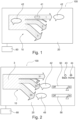
- Fig. 1 and Fig. 2 show a monitoring system 100 for a vehicle.
- the monitoring system 100 is configured to monitor an energy flow in the vehicle from an energy storage system to one or more sub-systems of the vehicle.
- the monitoring system 100 provides information about overall energy consumption of the vehicle as well as an energy consumption of each sub-system.
- the monitoring system 100 is further configured to manually and individually adjust the energy consumption of the sub-system.
- the sub-systems may be for example compartment heating and cooling system, battery heating and cooling system, defogging system, stereo system, lighting system, propulsion system, brake system etc.
- the monitoring system 100 comprises a display unit 20, an adjustment tool 50 and a control unit 60.
- the control unit 60 may be an electronic control unit and connected to various systems and sensors of the vehicle to collect continuously information on a current state of the vehicle.
- the control unit 60 generates image data according to the collected information to create an energy flow map 10.
- the energy flow map 10 may illustrate the energy flow from the energy storage system to one or more sub-systems and/or sub-devices of the vehicle based on electrical, mechanical, thermal energy consumption and/or mass transport in the vehicle.
- the display unit 20 is configured to visualize image data received from the control unit 60 and to display the energy flow map 10.
- the display unit 20 may be integrated in a Center Stack Display (SCD), Drivers Information Module (DIM) and/or Infotainment Head Unit (IHU).
- SCD Center Stack Display
- DIM Drivers Information Module
- IHU Infotainment Head Unit
- the display unit 20 may be further configured to visualize, for example vehicle information, entertainment programs, navigation assistance and/or any application set by the user.
- a graphical user interface (GUI) may be embedded to realize an interaction with the user via the display unit 20.
- the energy flow map 10 is represented as a Sankey flow diagram. Such diagram has a breakdown structure to show a flow from a higher system (root) to sub-systems (branches). Accordingly, the energy flow map 10 exhibits the energy flow from the energy storage system to the sub-systems of the vehicle and from the sub-systems to respective sub-devices and/or sub-elements. Each energy flow between two systems may be connected via a schematic element such as an arrow. To indicate a different level of the linked system, the arrows may have different colors and/or thickness.
- Each arrow of the energy flow map 10 can be individually selected. Hence, the energy flow map 10 may be zoomed into a lower level of the sub-system by touching the respective arrow. Additionally, the energy flow map 10 may be zoomed out to a higher level of the sub-system by touching the root area of the energy flow map 10 and/or clicking a return icon 43 or home icon 44.
- the energy flow map 10 comprises at least one adjustment tool 50 configured to receive user's input to adjust the energy consumption.
- the adjustment tool 50 is preferably arranged to individually set parameter of each sub-system, i.e. each arrow by the user for optimizing the energy consumption of the respective sub-system.
- the parameter may be variable by means of a scalar.
- the adjustment tool 50 may also comprise an on/off function. Accordingly, the adjustment tool 50 may be controlled graphically over the display unit 20.
- each arrow of the energy flow map 10 may have a different color or thickness to indicate which energy consumption is necessary, thus may not be changed and which energy consumption is optional. For instance, an arrow for the necessary energy consumption may be marked red whereas an arrow for the optional energy consumption may be marked green. Additionally or alternatively to the graphical indicator, the necessary and the optional energy consumption are marked with a text.
- the control unit 60 is further configured to implement displaying an explanatory text 42 of the current energy consumption and/or a suggestion text 45.
- the control unit 60 may allow the display unit 20 to show a short explanation on the current energy consumption of the respective sub-system. Additionally or alternatively, the control unit 60 is configured to calculate an optimal energy consumption based on the current energy consumption and may allow the display unit 20 to show a suggestion text 45 for optimizing the energy consumption.
- the explanatory text 42 and/or the suggestion text 45 can be directly arranged alongside the corresponding sub-system, i.e. arrow or displayed as a pop-up text by clicking a corresponding icon 41 arranged on each arrow.
- the display unit 20 can be divided into a first section and a second section.
- the first section depicts the energy flow map 10 and the second section displays the explanatory text 42, the suggestion text 45 and/or the adjustment tool 50. Accordingly, the user may easily obtain an overview over the energy flow inside the vehicle from the energy storage system to the sub-systems and optimize the energy consumption depending on the current situation of the vehicle.
- Fig 1 shows an entire energy consumption of the vehicle at a first level of the energy flow map 10. Entire energy from the energy storage system with 100% battery power is transferred to propulsion system 1 (25%), friction losses (5%) compartment system 2 (30%) and battery heating/cooling system 3 (40%).
- the explanatory texts 42 for each arrow may be automatically shown alongside each sub-system or arrow or by activating the pop-up icon 41. The user may reach a second level by clicking one of the arrow, for instance the battery heating/cooling system 3.
- Fig. 2 shows the energy flow map 10 in the second level to which sub-system the energy of the battery heating/cooling system 3 is transferred.
- the energy flow from the heating/cooling system 3 is subdivided in the second level such that the energy is distributed for battery heating for function 31 (25%), sensors 32 (5%), battery heating for performance 33 (20%) and battery heating for fast charging 34 (50%).
- the adjustment tool 50 i.e. deactivating the battery heating for performance and the battery heating for fast charging, the vehicle may drive with a lower performance and longer charging time but the energy consumption of the battery heating/cooling system 2 can be reduced.
- the compartment system 3 can be selected in the first level of the energy flow map 10. Accordingly, in the second level of the energy flow map 10 it is represented that to which sub-system the energy of the compartment system 3 is transferred.
- the energy consumption of the compartment system 3 may be divided into deicing windows and rear mirrors, internal lighting, seat heating and sound system and venting system.
- the energy flow map 10 may show the next level, how the energy consumption of the venting system is distributed.
- the user may reach the next detailed level, which may support the user to make a right decision to adjust a parameter of each sub-system or element to optimize and save the energy consumption of the vehicle.
Landscapes
- Engineering & Computer Science (AREA)
- Mechanical Engineering (AREA)
- Transportation (AREA)
- Chemical & Material Sciences (AREA)
- Combustion & Propulsion (AREA)
- Automation & Control Theory (AREA)
- Power Engineering (AREA)
- Sustainable Energy (AREA)
- Sustainable Development (AREA)
- Human Computer Interaction (AREA)
- Life Sciences & Earth Sciences (AREA)
- Electric Propulsion And Braking For Vehicles (AREA)
- Instrument Panels (AREA)
Claims (15)
- Überwachungssystem (100) für ein Fahrzeug, umfassend• eine Anzeigeeinheit (20),• ein Einstellwerkzeug (50) und• eine Steuereinheit (60), wobei die Steuereinheit (60) eingerichtet ist, eine Energieflusskarte (10) zu erzeugen, die einen Energiefluss von einem Energiespeichersystem zu mindestens einem Teilsystem des Fahrzeugs zeigt, wobei die Anzeigeeinheit (20) eingerichtet ist, die Energieflusskarte (10) anzuzeigen, wobei die Anzeigeeinheit (20) eingerichtet ist, das mindestens eine Teilsystem grafisch auf der Energieflusskarte (10) hervorzuheben, um den aktuellen Energieverbrauch des Teilsystems anzuzeigen, wobei die Steuereinheit (60) ferner eingerichtet ist, den Energieverbrauch des Teilsystems basierend auf einer Benutzereingabe am Einstellwerkzeug (50) anzupassen, wobei das Einstellwerkzeug (50) in die Anzeigeeinheit (20) integriert und grafisch steuerbar eingerichtet ist, und wobei die Anzeigeeinheit (20) eingerichtet ist, ein niedrigeres Niveau des Teilsystems grafisch auf der Energieflusskarte (10) hervorzuheben.
- Überwachungssystem (100) nach Anspruch 1, wobei die Anzeigeeinheit (20) eingerichtet ist, die Energieflusskarte (10) mittels eines Flussdiagramms anzuzeigen.
- Überwachungssystem (100) nach Anspruch 1 oder 2, wobei die Anzeigeeinheit (20) eingerichtet ist, ein höheres Niveau des Teilsystems grafisch auf der Energieflusskarte (10) hervorzuheben.
- Überwachungssystem (100) nach den vorhergehenden Ansprüchen, wobei die Steuereinheit (60) eingerichtet ist, den Energieverbrauch in Bezug auf die Benutzereingabe zu simulieren und ein Ergebnis auf der Anzeigeeinheit (20) anzuzeigen.
- Überwachungssystem (100) nach einem der vorhergehenden Ansprüche, wobei die Steuereinheit (60) eingerichtet ist, einen erläuternden Text (42) des aktuellen Energieverbrauchs auf der Anzeigeeinheit (20) anzuzeigen.
- Überwachungssystem (100) nach einem der vorhergehenden Ansprüche, wobei die Steuereinheit (60) eingerichtet ist, einen optimalen Energieverbrauch basierend auf dem aktuellen Energieverbrauch des Fahrzeugs und des Teilsystems zu berechnen und einen Vorschlagstext (45) zur Optimierung des Energieverbrauchs auf der Anzeigeeinheit (20) anzuzeigen.
- Überwachungssystem (100) nach einem der vorhergehenden Ansprüche, wobei die Steuereinheit (60) eingerichtet ist, einen notwendigen Energieverbrauch und/oder einen optionalen Energieverbrauch auf der Anzeigeeinheit (20) anzuzeigen.
- Überwachungssystem (100) nach einem der vorhergehenden Ansprüche, wobei die Steuereinheit (60) eingerichtet ist, die Energieflusskarte (10) mit einem Indikator anzuzeigen, um zwischen dem notwendigen Energieverbrauch und dem optionalen Energieverbrauch und/oder dem Energieverbrauch mehrerer Teilsysteme des Fahrzeugs zu unterscheiden.
- Überwachungssystem (100) nach einem der Ansprüche 7 oder 8, wobei die Steuereinheit (60) eingerichtet ist, die Benutzereingabe zur Anpassung des notwendigen Energieverbrauchs abzulehnen und/oder selektiv zuzulassen, dass ein Benutzer den optionalen Energieverbrauch anpasst.
- Überwachungssystem (100) nach einem der vorhergehenden Ansprüche, wobei die Anzeigeeinheit (20) einen ersten Abschnitt und einen zweiten Abschnitt umfasst, wobei der erste Abschnitt eingerichtet ist, die Energieflusskarte (10) anzuzeigen, und der zweite Abschnitt eingerichtet ist, den erläuternden Text (42) und/oder den Vorschlagstext (45) anzuzeigen.
- Überwachungssystem (100) nach einem der vorhergehenden Ansprüche, wobei die Steuereinheit (60) eingerichtet ist, den erläuternden Text (42) und/oder den Vorschlagstext (45) mittels eines Pop-ups auf der Anzeigeeinheit (20) anzuzeigen.
- Fahrzeug umfassend ein Überwachungssystem (100) nach einem der Ansprüche 1 bis 11.
- Fahrzeug nach Anspruch 12, wobei das Überwachungssystem (100) eingerichtet ist, im Falle eines automatischen Überwachungsmodus des Fahrzeugs deaktiviert zu werden.
- Verfahren zur Überwachung eines Fahrzeugs, umfassend• Erzeugen einer Energieflusskarte (10), die einen Energiefluss von einem Energiespeichersystem zu mindestens einem Teilsystem des Fahrzeugs zeigt,• Anzeigen der Energieflusskarte (10) auf einer Anzeigeeinheit (20),• Zoomen in die Energieflusskarte (10), um den aktuellen Energieverbrauch des Teilsystems anzuzeigen,• Anpassen des Energieverbrauchs des Teilsystems basierend auf einer Benutzereingabe an ein Einstellwerkzeug (50), und• Grafisches Hervorheben eines niedrigeren Niveaus des Teilsystems auf der Energieflusskarte (10), wobei das Einstellwerkzeug (50) in die Anzeigeeinheit (20) integriert und grafisch steuerbar eingerichtet ist.
- Computerelement zur Überwachung eines Fahrzeugs nach Anspruch 13, das, wenn es von einem Verarbeitungselement ausgeführt wird, eingerichtet ist, die Verfahrensschritte des Anspruchs 14 auszuführen.
Priority Applications (3)
| Application Number | Priority Date | Filing Date | Title |
|---|---|---|---|
| EP21178559.7A EP4101676B1 (de) | 2021-06-09 | 2021-06-09 | Überwachungssystem für fahrzeuge |
| US17/661,951 US12017673B2 (en) | 2021-06-09 | 2022-05-04 | Monitoring system for a vehicle |
| CN202210511140.XA CN115447377B (zh) | 2021-06-09 | 2022-05-11 | 用于车辆的监控系统 |
Applications Claiming Priority (1)
| Application Number | Priority Date | Filing Date | Title |
|---|---|---|---|
| EP21178559.7A EP4101676B1 (de) | 2021-06-09 | 2021-06-09 | Überwachungssystem für fahrzeuge |
Publications (2)
| Publication Number | Publication Date |
|---|---|
| EP4101676A1 EP4101676A1 (de) | 2022-12-14 |
| EP4101676B1 true EP4101676B1 (de) | 2024-08-28 |
Family
ID=76374904
Family Applications (1)
| Application Number | Title | Priority Date | Filing Date |
|---|---|---|---|
| EP21178559.7A Active EP4101676B1 (de) | 2021-06-09 | 2021-06-09 | Überwachungssystem für fahrzeuge |
Country Status (3)
| Country | Link |
|---|---|
| US (1) | US12017673B2 (de) |
| EP (1) | EP4101676B1 (de) |
| CN (1) | CN115447377B (de) |
Family Cites Families (13)
| Publication number | Priority date | Publication date | Assignee | Title |
|---|---|---|---|---|
| KR101118377B1 (ko) * | 2004-06-30 | 2012-03-08 | 포드 모터 캄파니 | 차량 정보 디스플레이부 및 차량 정보 디스플레이 방법 |
| JP4802046B2 (ja) * | 2006-06-14 | 2011-10-26 | トヨタホーム株式会社 | 建物の電力監視システム |
| US20120143410A1 (en) * | 2010-12-01 | 2012-06-07 | Aptera Motors, Inc. | Interactive driver system for an electric vehicle |
| KR101819941B1 (ko) * | 2011-01-27 | 2018-01-18 | 현대모비스 주식회사 | 에너지 흐름 표시 장치 |
| DE102011116313A1 (de) * | 2011-10-18 | 2013-04-18 | Daimler Ag | Anzeige von Energieflüssen in einem Hybridkraftfahrzeug |
| KR101620400B1 (ko) * | 2011-12-26 | 2016-05-23 | 엘지전자 주식회사 | 전기 차량의 제어 장치 및 그 방법 |
| DE102014006319A1 (de) * | 2014-04-30 | 2015-11-05 | Avl List Gmbh | System zur Beurteilung und/oder Optimierung des Betriebsverhaltens eines Fahrzeugs |
| US10479298B2 (en) * | 2014-09-08 | 2019-11-19 | Mahindra Electric Mobility Limited | Intelligent determination and usage of energy in energy systems |
| US10248146B2 (en) * | 2015-10-14 | 2019-04-02 | Honeywell International Inc. | System for dynamic control with interactive visualization to optimize energy consumption |
| DE102016220957A1 (de) * | 2016-10-25 | 2018-04-26 | Robert Bosch Gmbh | Verfahren zum Betreiben eines Bordnetzes |
| CN107962961B (zh) * | 2017-11-22 | 2024-08-09 | 广东易百珑智能科技有限公司 | 车辆无线充电系统及其无线充电方法 |
| EP3725579B1 (de) * | 2017-12-15 | 2021-08-18 | Nissan Motor Co., Ltd. | Betriebszustandsanzeigeverfahren und betriebszustandsanzeigesystem |
| US11396246B2 (en) * | 2018-10-15 | 2022-07-26 | Ford Global Technologies, Llc | Energy-consumption detection of vehicles in an off state |
-
2021
- 2021-06-09 EP EP21178559.7A patent/EP4101676B1/de active Active
-
2022
- 2022-05-04 US US17/661,951 patent/US12017673B2/en active Active
- 2022-05-11 CN CN202210511140.XA patent/CN115447377B/zh active Active
Also Published As
| Publication number | Publication date |
|---|---|
| EP4101676A1 (de) | 2022-12-14 |
| CN115447377B (zh) | 2025-11-18 |
| US12017673B2 (en) | 2024-06-25 |
| US20220396283A1 (en) | 2022-12-15 |
| CN115447377A (zh) | 2022-12-09 |
Similar Documents
| Publication | Publication Date | Title |
|---|---|---|
| JP5859614B2 (ja) | 車両用表示装置 | |
| US6988246B2 (en) | Touch sensitive input and display arrangement for controlling and monitoring aircraft cabin systems | |
| JP7421493B2 (ja) | ユーザーインターフェース及び空調機を制御するための方法及びシステム | |
| US20110209079A1 (en) | Graphical display with hierarchical gauge placement | |
| CN102458031B (zh) | 用于等离子体应用和/或感应加热应用的功率供给系统 | |
| CN109421469B (zh) | 操作多通道设备的方法和装置以及交通工具和计算机程序 | |
| ES2867677T3 (es) | Interfaz de usuario y método para ajustar una configuración de un medio de transporte por medio de una unidad de visualización de una interfaz de usuario | |
| US20180292953A1 (en) | System and Method for Displaying an Electronic Checklist | |
| US20140218307A1 (en) | Method and apparatus for providing information related to an in-vehicle function | |
| US20210070145A1 (en) | Grid for temperature control and fan speed | |
| JP6554120B2 (ja) | ディスプレイシステム | |
| CN104678796B (zh) | 用于显示飞行器信息的方法和系统 | |
| JP2017049788A (ja) | 車載情報処理装置 | |
| JP5115767B2 (ja) | 車両用入力システム | |
| EP4101676B1 (de) | Überwachungssystem für fahrzeuge | |
| CN102712233A (zh) | 用于空调装置的操作单元 | |
| WO2021053842A1 (ja) | 制御装置、端末装置及び方法 | |
| JPH10160229A (ja) | 空調用集中管理装置 | |
| US20240308340A1 (en) | Method for displaying graphical data on an electronic display | |
| CA2694543A1 (en) | Graphical display with hierarchical gauge placement | |
| EP2649943A1 (de) | Verfahren zur implementierung einer bearbeitungsfunktion in einem benutzermenü | |
| US20230132873A1 (en) | Vehicle and control method thereof | |
| CN117615929A (zh) | 用于管控车辆的空气调节系统的管控方法和管控装置 | |
| CN113978328B (zh) | 控制方法及装置、车辆及存储介质 | |
| Horváth et al. | Analysis of in-vehicle information systems from a cognitive perspective |
Legal Events
| Date | Code | Title | Description |
|---|---|---|---|
| PUAI | Public reference made under article 153(3) epc to a published international application that has entered the european phase |
Free format text: ORIGINAL CODE: 0009012 |
|
| STAA | Information on the status of an ep patent application or granted ep patent |
Free format text: STATUS: REQUEST FOR EXAMINATION WAS MADE |
|
| 17P | Request for examination filed |
Effective date: 20220215 |
|
| AK | Designated contracting states |
Kind code of ref document: A1 Designated state(s): AL AT BE BG CH CY CZ DE DK EE ES FI FR GB GR HR HU IE IS IT LI LT LU LV MC MK MT NL NO PL PT RO RS SE SI SK SM TR |
|
| GRAP | Despatch of communication of intention to grant a patent |
Free format text: ORIGINAL CODE: EPIDOSNIGR1 |
|
| STAA | Information on the status of an ep patent application or granted ep patent |
Free format text: STATUS: GRANT OF PATENT IS INTENDED |
|
| INTG | Intention to grant announced |
Effective date: 20240424 |
|
| GRAS | Grant fee paid |
Free format text: ORIGINAL CODE: EPIDOSNIGR3 |
|
| GRAA | (expected) grant |
Free format text: ORIGINAL CODE: 0009210 |
|
| STAA | Information on the status of an ep patent application or granted ep patent |
Free format text: STATUS: THE PATENT HAS BEEN GRANTED |
|
| AK | Designated contracting states |
Kind code of ref document: B1 Designated state(s): AL AT BE BG CH CY CZ DE DK EE ES FI FR GB GR HR HU IE IS IT LI LT LU LV MC MK MT NL NO PL PT RO RS SE SI SK SM TR |
|
| REG | Reference to a national code |
Ref country code: CH Ref legal event code: EP |
|
| P01 | Opt-out of the competence of the unified patent court (upc) registered |
Free format text: CASE NUMBER: APP_45260/2024 Effective date: 20240805 |
|
| REG | Reference to a national code |
Ref country code: DE Ref legal event code: R096 Ref document number: 602021017769 Country of ref document: DE |
|
| REG | Reference to a national code |
Ref country code: IE Ref legal event code: FG4D |
|
| REG | Reference to a national code |
Ref country code: LT Ref legal event code: MG9D |
|
| PG25 | Lapsed in a contracting state [announced via postgrant information from national office to epo] |
Ref country code: NO Free format text: LAPSE BECAUSE OF FAILURE TO SUBMIT A TRANSLATION OF THE DESCRIPTION OR TO PAY THE FEE WITHIN THE PRESCRIBED TIME-LIMIT Effective date: 20241128 |
|
| REG | Reference to a national code |
Ref country code: AT Ref legal event code: MK05 Ref document number: 1717611 Country of ref document: AT Kind code of ref document: T Effective date: 20240828 |
|
| PG25 | Lapsed in a contracting state [announced via postgrant information from national office to epo] |
Ref country code: PT Free format text: LAPSE BECAUSE OF FAILURE TO SUBMIT A TRANSLATION OF THE DESCRIPTION OR TO PAY THE FEE WITHIN THE PRESCRIBED TIME-LIMIT Effective date: 20241230 Ref country code: NL Free format text: LAPSE BECAUSE OF FAILURE TO SUBMIT A TRANSLATION OF THE DESCRIPTION OR TO PAY THE FEE WITHIN THE PRESCRIBED TIME-LIMIT Effective date: 20240828 Ref country code: PL Free format text: LAPSE BECAUSE OF FAILURE TO SUBMIT A TRANSLATION OF THE DESCRIPTION OR TO PAY THE FEE WITHIN THE PRESCRIBED TIME-LIMIT Effective date: 20240828 Ref country code: GR Free format text: LAPSE BECAUSE OF FAILURE TO SUBMIT A TRANSLATION OF THE DESCRIPTION OR TO PAY THE FEE WITHIN THE PRESCRIBED TIME-LIMIT Effective date: 20241129 Ref country code: FI Free format text: LAPSE BECAUSE OF FAILURE TO SUBMIT A TRANSLATION OF THE DESCRIPTION OR TO PAY THE FEE WITHIN THE PRESCRIBED TIME-LIMIT Effective date: 20240828 |
|
| PG25 | Lapsed in a contracting state [announced via postgrant information from national office to epo] |
Ref country code: BG Free format text: LAPSE BECAUSE OF FAILURE TO SUBMIT A TRANSLATION OF THE DESCRIPTION OR TO PAY THE FEE WITHIN THE PRESCRIBED TIME-LIMIT Effective date: 20240828 |
|
| PG25 | Lapsed in a contracting state [announced via postgrant information from national office to epo] |
Ref country code: LV Free format text: LAPSE BECAUSE OF FAILURE TO SUBMIT A TRANSLATION OF THE DESCRIPTION OR TO PAY THE FEE WITHIN THE PRESCRIBED TIME-LIMIT Effective date: 20240828 |
|
| REG | Reference to a national code |
Ref country code: NL Ref legal event code: MP Effective date: 20240828 |
|
| PG25 | Lapsed in a contracting state [announced via postgrant information from national office to epo] |
Ref country code: AT Free format text: LAPSE BECAUSE OF FAILURE TO SUBMIT A TRANSLATION OF THE DESCRIPTION OR TO PAY THE FEE WITHIN THE PRESCRIBED TIME-LIMIT Effective date: 20240828 Ref country code: IS Free format text: LAPSE BECAUSE OF FAILURE TO SUBMIT A TRANSLATION OF THE DESCRIPTION OR TO PAY THE FEE WITHIN THE PRESCRIBED TIME-LIMIT Effective date: 20241228 |
|
| PG25 | Lapsed in a contracting state [announced via postgrant information from national office to epo] |
Ref country code: HR Free format text: LAPSE BECAUSE OF FAILURE TO SUBMIT A TRANSLATION OF THE DESCRIPTION OR TO PAY THE FEE WITHIN THE PRESCRIBED TIME-LIMIT Effective date: 20240828 |
|
| PG25 | Lapsed in a contracting state [announced via postgrant information from national office to epo] |
Ref country code: ES Free format text: LAPSE BECAUSE OF FAILURE TO SUBMIT A TRANSLATION OF THE DESCRIPTION OR TO PAY THE FEE WITHIN THE PRESCRIBED TIME-LIMIT Effective date: 20240828 Ref country code: RS Free format text: LAPSE BECAUSE OF FAILURE TO SUBMIT A TRANSLATION OF THE DESCRIPTION OR TO PAY THE FEE WITHIN THE PRESCRIBED TIME-LIMIT Effective date: 20241128 |
|
| PG25 | Lapsed in a contracting state [announced via postgrant information from national office to epo] |
Ref country code: RS Free format text: LAPSE BECAUSE OF FAILURE TO SUBMIT A TRANSLATION OF THE DESCRIPTION OR TO PAY THE FEE WITHIN THE PRESCRIBED TIME-LIMIT Effective date: 20241128 Ref country code: PT Free format text: LAPSE BECAUSE OF FAILURE TO SUBMIT A TRANSLATION OF THE DESCRIPTION OR TO PAY THE FEE WITHIN THE PRESCRIBED TIME-LIMIT Effective date: 20241230 Ref country code: PL Free format text: LAPSE BECAUSE OF FAILURE TO SUBMIT A TRANSLATION OF THE DESCRIPTION OR TO PAY THE FEE WITHIN THE PRESCRIBED TIME-LIMIT Effective date: 20240828 Ref country code: NO Free format text: LAPSE BECAUSE OF FAILURE TO SUBMIT A TRANSLATION OF THE DESCRIPTION OR TO PAY THE FEE WITHIN THE PRESCRIBED TIME-LIMIT Effective date: 20241128 Ref country code: NL Free format text: LAPSE BECAUSE OF FAILURE TO SUBMIT A TRANSLATION OF THE DESCRIPTION OR TO PAY THE FEE WITHIN THE PRESCRIBED TIME-LIMIT Effective date: 20240828 Ref country code: LV Free format text: LAPSE BECAUSE OF FAILURE TO SUBMIT A TRANSLATION OF THE DESCRIPTION OR TO PAY THE FEE WITHIN THE PRESCRIBED TIME-LIMIT Effective date: 20240828 Ref country code: IS Free format text: LAPSE BECAUSE OF FAILURE TO SUBMIT A TRANSLATION OF THE DESCRIPTION OR TO PAY THE FEE WITHIN THE PRESCRIBED TIME-LIMIT Effective date: 20241228 Ref country code: HR Free format text: LAPSE BECAUSE OF FAILURE TO SUBMIT A TRANSLATION OF THE DESCRIPTION OR TO PAY THE FEE WITHIN THE PRESCRIBED TIME-LIMIT Effective date: 20240828 Ref country code: GR Free format text: LAPSE BECAUSE OF FAILURE TO SUBMIT A TRANSLATION OF THE DESCRIPTION OR TO PAY THE FEE WITHIN THE PRESCRIBED TIME-LIMIT Effective date: 20241129 Ref country code: FI Free format text: LAPSE BECAUSE OF FAILURE TO SUBMIT A TRANSLATION OF THE DESCRIPTION OR TO PAY THE FEE WITHIN THE PRESCRIBED TIME-LIMIT Effective date: 20240828 Ref country code: ES Free format text: LAPSE BECAUSE OF FAILURE TO SUBMIT A TRANSLATION OF THE DESCRIPTION OR TO PAY THE FEE WITHIN THE PRESCRIBED TIME-LIMIT Effective date: 20240828 Ref country code: BG Free format text: LAPSE BECAUSE OF FAILURE TO SUBMIT A TRANSLATION OF THE DESCRIPTION OR TO PAY THE FEE WITHIN THE PRESCRIBED TIME-LIMIT Effective date: 20240828 Ref country code: AT Free format text: LAPSE BECAUSE OF FAILURE TO SUBMIT A TRANSLATION OF THE DESCRIPTION OR TO PAY THE FEE WITHIN THE PRESCRIBED TIME-LIMIT Effective date: 20240828 |
|
| PG25 | Lapsed in a contracting state [announced via postgrant information from national office to epo] |
Ref country code: DK Free format text: LAPSE BECAUSE OF FAILURE TO SUBMIT A TRANSLATION OF THE DESCRIPTION OR TO PAY THE FEE WITHIN THE PRESCRIBED TIME-LIMIT Effective date: 20240828 Ref country code: SM Free format text: LAPSE BECAUSE OF FAILURE TO SUBMIT A TRANSLATION OF THE DESCRIPTION OR TO PAY THE FEE WITHIN THE PRESCRIBED TIME-LIMIT Effective date: 20240828 Ref country code: RO Free format text: LAPSE BECAUSE OF FAILURE TO SUBMIT A TRANSLATION OF THE DESCRIPTION OR TO PAY THE FEE WITHIN THE PRESCRIBED TIME-LIMIT Effective date: 20240828 |
|
| PG25 | Lapsed in a contracting state [announced via postgrant information from national office to epo] |
Ref country code: EE Free format text: LAPSE BECAUSE OF FAILURE TO SUBMIT A TRANSLATION OF THE DESCRIPTION OR TO PAY THE FEE WITHIN THE PRESCRIBED TIME-LIMIT Effective date: 20240828 |
|
| PG25 | Lapsed in a contracting state [announced via postgrant information from national office to epo] |
Ref country code: CZ Free format text: LAPSE BECAUSE OF FAILURE TO SUBMIT A TRANSLATION OF THE DESCRIPTION OR TO PAY THE FEE WITHIN THE PRESCRIBED TIME-LIMIT Effective date: 20240828 |
|
| PG25 | Lapsed in a contracting state [announced via postgrant information from national office to epo] |
Ref country code: SK Free format text: LAPSE BECAUSE OF FAILURE TO SUBMIT A TRANSLATION OF THE DESCRIPTION OR TO PAY THE FEE WITHIN THE PRESCRIBED TIME-LIMIT Effective date: 20240828 Ref country code: IT Free format text: LAPSE BECAUSE OF FAILURE TO SUBMIT A TRANSLATION OF THE DESCRIPTION OR TO PAY THE FEE WITHIN THE PRESCRIBED TIME-LIMIT Effective date: 20240828 |
|
| REG | Reference to a national code |
Ref country code: DE Ref legal event code: R097 Ref document number: 602021017769 Country of ref document: DE |
|
| PLBE | No opposition filed within time limit |
Free format text: ORIGINAL CODE: 0009261 |
|
| STAA | Information on the status of an ep patent application or granted ep patent |
Free format text: STATUS: NO OPPOSITION FILED WITHIN TIME LIMIT |
|
| PGFP | Annual fee paid to national office [announced via postgrant information from national office to epo] |
Ref country code: DE Payment date: 20250520 Year of fee payment: 5 |
|
| PGFP | Annual fee paid to national office [announced via postgrant information from national office to epo] |
Ref country code: GB Payment date: 20250520 Year of fee payment: 5 |
|
| PGFP | Annual fee paid to national office [announced via postgrant information from national office to epo] |
Ref country code: FR Payment date: 20250520 Year of fee payment: 5 |
|
| 26N | No opposition filed |
Effective date: 20250530 |
|
| PG25 | Lapsed in a contracting state [announced via postgrant information from national office to epo] |
Ref country code: SE Free format text: LAPSE BECAUSE OF FAILURE TO SUBMIT A TRANSLATION OF THE DESCRIPTION OR TO PAY THE FEE WITHIN THE PRESCRIBED TIME-LIMIT Effective date: 20240828 |
|
| REG | Reference to a national code |
Ref country code: CH Ref legal event code: H13 Free format text: ST27 STATUS EVENT CODE: U-0-0-H10-H13 (AS PROVIDED BY THE NATIONAL OFFICE) Effective date: 20260127 |
|
| PG25 | Lapsed in a contracting state [announced via postgrant information from national office to epo] |
Ref country code: MC Free format text: LAPSE BECAUSE OF FAILURE TO SUBMIT A TRANSLATION OF THE DESCRIPTION OR TO PAY THE FEE WITHIN THE PRESCRIBED TIME-LIMIT Effective date: 20240828 |
|
| PG25 | Lapsed in a contracting state [announced via postgrant information from national office to epo] |
Ref country code: LU Free format text: LAPSE BECAUSE OF NON-PAYMENT OF DUE FEES Effective date: 20250609 |
|
| REG | Reference to a national code |
Ref country code: BE Ref legal event code: MM Effective date: 20250630 |
|
| PG25 | Lapsed in a contracting state [announced via postgrant information from national office to epo] |
Ref country code: IE Free format text: LAPSE BECAUSE OF NON-PAYMENT OF DUE FEES Effective date: 20250609 |
|
| PG25 | Lapsed in a contracting state [announced via postgrant information from national office to epo] |
Ref country code: BE Free format text: LAPSE BECAUSE OF NON-PAYMENT OF DUE FEES Effective date: 20250630 |