EP4101397B1 - Système d'insertion d'un dispositif d'occlusion et unité d'insertion - Google Patents
Système d'insertion d'un dispositif d'occlusion et unité d'insertion Download PDFInfo
- Publication number
- EP4101397B1 EP4101397B1 EP22187317.7A EP22187317A EP4101397B1 EP 4101397 B1 EP4101397 B1 EP 4101397B1 EP 22187317 A EP22187317 A EP 22187317A EP 4101397 B1 EP4101397 B1 EP 4101397B1
- Authority
- EP
- European Patent Office
- Prior art keywords
- occluder
- inner tube
- outer tube
- thread
- distal end
- Prior art date
- Legal status (The legal status is an assumption and is not a legal conclusion. Google has not performed a legal analysis and makes no representation as to the accuracy of the status listed.)
- Active
Links
Images


Classifications
-
- A—HUMAN NECESSITIES
- A61—MEDICAL OR VETERINARY SCIENCE; HYGIENE
- A61B—DIAGNOSIS; SURGERY; IDENTIFICATION
- A61B17/00—Surgical instruments, devices or methods
- A61B17/12—Surgical instruments, devices or methods for ligaturing or otherwise compressing tubular parts of the body, e.g. blood vessels or umbilical cord
- A61B17/12022—Occluding by internal devices, e.g. balloons or releasable wires
- A61B17/12099—Occluding by internal devices, e.g. balloons or releasable wires characterised by the location of the occluder
- A61B17/12122—Occluding by internal devices, e.g. balloons or releasable wires characterised by the location of the occluder within the heart
-
- A—HUMAN NECESSITIES
- A61—MEDICAL OR VETERINARY SCIENCE; HYGIENE
- A61B—DIAGNOSIS; SURGERY; IDENTIFICATION
- A61B17/00—Surgical instruments, devices or methods
- A61B17/12—Surgical instruments, devices or methods for ligaturing or otherwise compressing tubular parts of the body, e.g. blood vessels or umbilical cord
- A61B17/12022—Occluding by internal devices, e.g. balloons or releasable wires
- A61B17/12027—Type of occlusion
- A61B17/12031—Type of occlusion complete occlusion
-
- A—HUMAN NECESSITIES
- A61—MEDICAL OR VETERINARY SCIENCE; HYGIENE
- A61B—DIAGNOSIS; SURGERY; IDENTIFICATION
- A61B17/00—Surgical instruments, devices or methods
- A61B17/12—Surgical instruments, devices or methods for ligaturing or otherwise compressing tubular parts of the body, e.g. blood vessels or umbilical cord
- A61B17/12022—Occluding by internal devices, e.g. balloons or releasable wires
- A61B17/12131—Occluding by internal devices, e.g. balloons or releasable wires characterised by the type of occluding device
- A61B17/12168—Occluding by internal devices, e.g. balloons or releasable wires characterised by the type of occluding device having a mesh structure
- A61B17/12172—Occluding by internal devices, e.g. balloons or releasable wires characterised by the type of occluding device having a mesh structure having a pre-set deployed three-dimensional shape
-
- A—HUMAN NECESSITIES
- A61—MEDICAL OR VETERINARY SCIENCE; HYGIENE
- A61B—DIAGNOSIS; SURGERY; IDENTIFICATION
- A61B17/00—Surgical instruments, devices or methods
- A61B17/12—Surgical instruments, devices or methods for ligaturing or otherwise compressing tubular parts of the body, e.g. blood vessels or umbilical cord
- A61B17/12022—Occluding by internal devices, e.g. balloons or releasable wires
- A61B17/12131—Occluding by internal devices, e.g. balloons or releasable wires characterised by the type of occluding device
- A61B17/12168—Occluding by internal devices, e.g. balloons or releasable wires characterised by the type of occluding device having a mesh structure
- A61B17/12177—Occluding by internal devices, e.g. balloons or releasable wires characterised by the type of occluding device having a mesh structure comprising additional materials, e.g. thrombogenic, having filaments, having fibers or being coated
-
- A—HUMAN NECESSITIES
- A61—MEDICAL OR VETERINARY SCIENCE; HYGIENE
- A61B—DIAGNOSIS; SURGERY; IDENTIFICATION
- A61B17/00—Surgical instruments, devices or methods
- A61B2017/00367—Details of actuation of instruments, e.g. relations between pushing buttons, or the like, and activation of the tool, working tip, or the like
-
- A—HUMAN NECESSITIES
- A61—MEDICAL OR VETERINARY SCIENCE; HYGIENE
- A61B—DIAGNOSIS; SURGERY; IDENTIFICATION
- A61B17/00—Surgical instruments, devices or methods
- A61B2017/00831—Material properties
- A61B2017/00867—Material properties shape memory effect
-
- A—HUMAN NECESSITIES
- A61—MEDICAL OR VETERINARY SCIENCE; HYGIENE
- A61B—DIAGNOSIS; SURGERY; IDENTIFICATION
- A61B17/00—Surgical instruments, devices or methods
- A61B17/12—Surgical instruments, devices or methods for ligaturing or otherwise compressing tubular parts of the body, e.g. blood vessels or umbilical cord
- A61B17/12022—Occluding by internal devices, e.g. balloons or releasable wires
- A61B2017/1205—Introduction devices
- A61B2017/12054—Details concerning the detachment of the occluding device from the introduction device
-
- A—HUMAN NECESSITIES
- A61—MEDICAL OR VETERINARY SCIENCE; HYGIENE
- A61B—DIAGNOSIS; SURGERY; IDENTIFICATION
- A61B90/00—Instruments, implements or accessories specially adapted for surgery or diagnosis and not covered by any of the groups A61B1/00 - A61B50/00, e.g. for luxation treatment or for protecting wound edges
- A61B90/39—Markers, e.g. radio-opaque or breast lesions markers
- A61B2090/3966—Radiopaque markers visible in an X-ray image
Definitions
- the invention relates to a system for introducing a self-expanding occluder into a patient and for releasing the occluder in the left auricle of the patient.
- the atrial appendages are outpouchings of the atria of the heart in mammals.
- the left atrial appendage medically known as the left atrial appendage (LAA)
- LAA left atrial appendage
- the left atrial appendage lies adjacent to the pulmonary artery and is a common site of blood clot formation, particularly in patients with atrial fibrillation. Preventing thrombi in the left atrial appendage therefore represents effective stroke prophylaxis in patients at risk.
- LAA Left Atrial Appendage
- occluders implants that are inserted into the ventricle and seal the access, for example, with a Teflon film.
- LAA Left Atrial Appendage
- These implants are inserted into the ventricle and anchored there, particularly using anchoring elements, so that they seal the access to the ventricle in a fluid-tight manner, particularly at their proximal end. Insertion is usually performed using endovascular techniques, i.e., with a delivery catheter through which the implant is delivered to the site of application.
- the occluders are especially in a reduced-volume form, it is transported to the site of use and expanded there. Self-expanding materials, such as shape memory alloys, are generally used for the occluders.
- Such an occluder is WO 2015/079023 A1 previously known.
- a guide wire To insert an occluder into the left auricle of a patient, it is known to use a guide wire.
- the guide wire is used, for example, as in the WO 2015/079023 A1 disclosed, is screwed onto an internal thread of the occluder using an external thread. The occluder is then moved to its intended position in the area of the left auricle. Once the occluder has assumed its self-expanded shape at the intended location, the guide wire can be released from the occluder by unscrewing the guide wire. This can, in particular, result in undesirable torque acting on the occluder and, in the worst case, even lead to the occluder becoming detached from its intended position. Consequently, there is a need to remedy these disadvantages.
- an occluder as easily as possible into an insertion position, which can in particular be a compressed position, in order to bring the occluder to the left auricle in this insertion position.
- a handling unit for inserting a prosthesis wherein two elements of the handling unit can be rotated relative to one another, so that an outer tube and an inner tube move translationally relative to one another and the shape expands from the gap that forms.
- WO 2006/036837 A2 discloses a system for introducing an occluder designed to close a patent foramen ovale.
- An inner tube of a The system's insertion unit is motion-coupled to a distal end of the occluder.
- US 2007/0135826 A1 discloses a system for introducing an occluder configured to occlude the left auricle of a patient.
- a distal end of an outer tube of an insertion unit of the system is disposed within the occluder during insertion of the occluder.
- the present invention is therefore based on the overall object of developing the known prior art.
- a system for introducing a self-expanding occluder into a patient and for releasing the occluder in the left auricle of the patient.
- the system comprises the occluder and an insertion unit with a drive unit and with an insertion catheter, which comprises an outer tube and an inner tube extending through the outer tube.
- a proximal end region of the occluder is motion-coupled to the outer tube, while a distal end region of the occluder is motion-coupled to the inner tube, wherein a distal end of the outer tube is arranged within the occluder.
- the drive unit interacts with the inner tube and the outer tube of the occluder in such a way that Actuation on the one hand the inner tube can be moved in the distal or proximal direction and on the other hand the outer tube can be moved in the proximal or distal direction, so that the proximal end and the distal end of the occluder can be moved away from or towards each other.
- the proximal end and the distal end of the occluder can be moved away from each other or towards each other.
- the inner tube can therefore first be moved in the distal direction while the outer tube is moved in the proximal direction. This allows the proximal end and the distal end of the occluder to be moved away from each other in order to bring the occluder into an insertion position. In this insertion position, the occluder is therefore compressed, so that it has an increased length but a reduced diameter. This allows it to be guided towards the left auricula cordis, particularly through blood vessels.
- the inner tube can be moved proximally, while the outer tube can be moved distally. This causes the proximal and distal ends of the occluder to move toward each other, with the occluder striving toward its self-expanding shape. The length of the occluder decreases while its diameter increases.
- the occluder is applied to the left auricula cordis in order to close the left auricula cordis by means of the occluder.
- a change in the position of the occluder can be brought about in a particularly simple manner in order to transfer the occluder into an insertion position in which the occluder can be brought particularly easily to the left auricula cordis of a patient, and to be able to release the occluder, whereby the occluder strives in particular for its self-expanded form and tightly closes the left auricula cordis after release.
- An advantageous development of the invention provides that the outer tube ends distally before the inner tube. This allows for a particularly simple coupling of the proximal end region of the occluder to the outer tube and the distal end region of the occluder to the inner tube.
- the occluder comprises a frame with a tubular proximal end region through which the insertion catheter is inserted into the occluder.
- the insertion catheter can be inserted into the occluder in a particularly simple manner.
- the distal end of the outer tube can be located in the distal direction immediately after the tubular proximal end region, so that the outer tube cooperates in particular with the tubular proximal end region of the occluder for movement coupling. It is conceivable that the outer tube is positively or non-positively connected to the tubular proximal end section.
- the occluder tends to move into its self-expanded form, so that, starting from the insertion position, the occluder can support the movement of the outer tube in a distal direction through its intrinsic tendency to the expanded position.
- the occluder comprises a cup-shaped distal end region on which the inner tube of the insertion catheter is arranged.
- the distal end region of the inner tube can therefore in particular be inserted into the cup-shaped distal end region of the occluder and terminate therein.
- the cup-shaped distal end region therefore in particular comprises a circular cylindrical jacket section and a base section. Consequently, a movement coupling can be provided between the inner tube and the distal end region of the occluder, in particular in the distal direction.
- the inner tube is arranged in a form-fitting or force-fitting manner in the distal cup-shaped end region.
- a movement coupling between the inner tube and the distal cup-shaped end region of the occluder can be provided even when the inner tube is moved in the proximal direction.
- the occluder strives particularly towards its self-expanded form, so that starting from the insertion position, the occluder can support the movement of the inner tube in the proximal direction by the intrinsic striving into the expanded position.
- the occluder can be transferred into an insertion position for insertion into a patient by a distal end of the inner tube and a distal end of the outer tube can be moved away from each other relative to each other, so that the proximal end and the distal end of the occluder can be moved away from each other.
- the occluder can in particular have a reduced diameter and thus be compressed.
- the occluder can have an increased length, so that in the insertion position the occluder has a reduced diameter but a greater length compared to the release position. In this insertion position, the occluder can be brought particularly easily closer to the left auricle.
- the distal ends of the inner tube and the outer tube can be moved toward one another to release the occluder, such that the proximal end and the distal end of the occluder can be moved toward one another.
- the occluder during the release process, tends to assume its self-expanded form, so that, starting from the insertion position of the occluder, upon movement of the inner tube in the proximal direction or the outer tube in the distal direction, the occluder intrinsically tends toward the expanded position.
- a central portion of the occluder between the proximal end and the distal end can be provided to maintain its position essentially unchanged during the release of the occluder.
- the distal ends of the inner tube and the outer tube are moved toward each other. so that the proximal end and the distal end of the occluder also move towards each other.
- the occluder can be designed to be self-expanding, it can be provided in particular that the occluder strives for its self-expanded position during the release process.
- the occluder In the final position, the occluder can come into contact with the inner side of the left auricula cordis and tightly close the left auricula cordis, in order to reduce the risk of thrombus formation and the resulting risk of stroke. In the final position, the occluder can either assume its self-expanded final shape. However, it is also conceivable that the final position of the occluder, in which it comes into sealing contact with the left auricula cordis, is already reached before the self-expanded final shape is reached and the occluder can then no longer deform.
- the occluder has a central axis that extends through the proximal end region and the distal end region.
- the occluder can run around this axis.
- the occluder can have a center point between the proximal end and the distal end along this axis.
- the proximal end and the distal end of the occluder are moved towards each other in such a way that the center point of the occluder maintains or essentially maintains its position. This can provide a particularly precise arrangement and release of the occluder on the left auricle.
- the occluder In its final position, the occluder can in particular have a spherical outer contour, so that the center point can also be the center point of the circular outer contour.
- the drive unit has a first transmission element with a first transmission thread, a second transmission element with a second transmission thread, and an actuating element actuatable by an operator with a first drive thread and a second drive thread.
- the first transmission element is motion-coupled to the inner tube.
- the second transmission element is motion-coupled to the outer tube.
- the first drive thread interacts with the first transmission thread, while the second drive thread interacts with the second transmission thread to move the distal ends of the outer tube and the inner tube towards or away from each other.
- a motion coupling between the drive unit and the outer tube or inner tube of the insertion catheter can thereby be provided.
- the first and second drive threads can be formed as a single piece.
- the actuating element can be formed as a single piece.
- the distal ends of the outer tube and the inner tube can therefore be moved towards or away from each other at the same time.
- the first transmission thread and the second transmission thread, as well as the first and the second drive thread are designed synchronously in such a way that when the actuating element is actuated, the inner tube and the outer tube be shifted by the same distance in the opposite direction.
- the first drive thread is designed as a first internal thread, which interacts with the first transmission thread, which is designed as an external thread.
- the second drive thread is advantageously designed as a second internal thread, which interacts with the second transmission thread, which is designed as an external thread.
- the first and second drive threads can be formed integrally with one another. Overall, this allows for a particularly simple coupling of motion and synchronous movement in opposite directions.
- the outer tube has at least one, in particular two or more, locking finger-like portions at its distal end region, which interact with the proximal end region of the occluder to couple the movement.
- the locking finger-like portion can interact, in particular, with the tubular proximal end section of the occluder and engage behind it, in particular, to couple the movement during a movement in the proximal direction.
- the outer tube can, in particular, be formed as a single piece.
- a particularly preferred development of the invention results from the fact that the first transmission element interacts with a Luer connection arranged on the inner tube for movement coupling with the inner tube.
- a Luer connector can therefore be arranged on the inner tube. This can, for example, be arranged on the first transmission element for movement coupling.
- a particularly preferred development of the invention provides that the locking finger-like section is arranged in a form-fitting manner at the proximal end region of the occluder when the inner tube is arranged in the occluder.
- the locking finger-like section is designed to be elastically flexible and, starting from a rest position, is deflected from the rest position after the inner tube has been inserted through the outer tube.
- the locking finger-like section cannot deflect radially inward, thus providing a stable form-fitting connection between the proximal end region of the occluder and the locking finger-like section.
- the inner tube can first be removed from the occluder. Once the inner tube has been removed from the occluder through the outer tube, the outer tube can then be removed from the occluder.
- the positive connection between the outer tube and the proximal end region of the occluder can only be released when the inner tube is withdrawn from the occluder through the outer tube.
- the distal end and the proximal end are moved toward each other by means of the outer tube and the inner tube. This forces the occluder into its self-expanding shape.
- the delivery catheter can be withdrawn from the occluder in a particularly simple manner by first withdrawing the inner tube from the occluder through the outer tube.
- the outer tube can then be withdrawn from the occluder, whereby, in particular, the locking finger-like section at the distal end of the outer tube can be elastically displaced radially inward in order to withdraw the outer tube from the tubular proximal end section of the occluder.
- This procedure can therefore essentially completely or even completely prevent undesired torque transmission from the delivery catheter to the occluder. This minimizes or eliminates the risk of the occluder being dislodged from its intended position at the left auricle when the delivery catheter is removed from the occluder. After removal of the delivery catheter, the occluder can fully expand into its self-expanded shape, thereby completely sealing the left auricle in a fluid-tight manner.
- the insertion unit comprises a housing that can be held by an operator, with the transmission elements and the actuating element being arranged in or on the housing.
- An operator for example a surgeon, can thus hold the housing in their hand, so that the housing can be designed like a handle.
- the transmission elements and/or the actuating element can be arranged in or on the housing.
- the actuating element is rotatably mounted on the housing.
- the housing may have a central longitudinal axis, and the actuating element may be rotatable about the central longitudinal axis.
- the actuating element may, in particular, be formed in one piece and, in particular, be hollow-cylindrical with an internal thread.
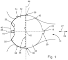
- Figure 1 shows, with reference number 10, the left auricula cordis of a patient.
- an occluder 12 is inserted into the auricula cordis sinistra 10 is used to close the access to the auricula cordis sinistra 10.
- the occluder 12 comprises a one-piece frame 14. This comprises a proximal tubular section 16 and a cup-shaped distal end section 18.
- the cup-shaped distal end section 18 comprises a circular cylindrical shell section 20 and a base section 22 to form a cup-shaped structure.
- the occluder has a net-like frame section 24.
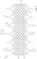
- This net-like frame section 24 is Figure 4 Particularly clearly visible in sectioned form.
- the net-like frame section 24 initially has a number of webs 26. These merge into a branching network of webs 25 to form the net structure.
- Diamond-shaped structures 28 are formed in the process. In the distal direction 29, the webs 25 converge again into individual webs 30, which open into the distal end section 18.
- the occluder 12 has a proximal hemisphere 32 and a distal hemisphere 35.
- first anchoring means 34 are provided in the area of the proximal hemisphere 32. These extend along a circular line along the circumference and are hook-shaped with end sections pointing in the proximal direction 27.
- second anchoring means 36 are formed in the area of the distal hemisphere 35. These also extend along a circular line along the circumference, have a rod-like shape and protrude obliquely from the circumferential surface in the proximal direction 27.
- the anchoring means 34, 36 are also formed integrally with the frame 14.
- the frame 14 of the occluder 12 consists of a self-expanding material, for example, a shape memory alloy, in particular a nitinol alloy.
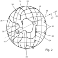
- the expanded shape imprinted on the occluder 12 is spherical (see FIG. Figure 2 ).
- the occluder 12 has a longitudinal axis 38 running in the proximal and distal directions through its center point. This longitudinal axis 38 also extends through the central longitudinal axis of the tubular proximal end section 16 and through the central longitudinal axis of the distal end section 18 (cf. Figure 2 ).
- the proximal hemisphere 32 is completely covered by a biological tissue 40. This biological tissue 40 is in particular designed as a biological membrane.
- the tissue 40 can be the pericardium membrane.
- the tissue 40 has openings such that the first anchoring means 34 protrude through the openings.
- the tissue 40 has an insertion opening for inserting an insertion catheter through the proximal tube section 16 into the occluder 12.
- the elastically flexible tissue 40 can contract such that the insertion opening is closed in a substantially fluid-tight manner, so that overall the tissue 40 closes the proximal hemisphere 32 in a substantially fluid-tight manner and thereby substantially covers the frame 14.
- the fabric is sewn to the frame 14 by means of PTFE threads.
- a number of X-ray markers 38 are placed circumferentially in the region of the proximal hemisphere 32. These markers enable precise positioning of the occluder 12 in the left auricle. Consequently, a surgeon can place the occluder 12 with particularly precise positioning.
- an occluder 12 with comparatively high biocompatibility can be provided. After the occluder 12 has been positioned on the left auricula cordis, the biological tissue 40 can be overgrown by the patient's natural tissue. Due to the biological tissue 40 used, there is a high overall biocompatibility and thus an increased probability of a successful surgical procedure to close the left auricula cordis.
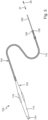
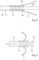
- Figure 5 shows an insertion unit 100.
- This comprises a drive unit 102 and an insertion catheter 104.
- the insertion catheter 104 comprises an inner tube 108 and an outer tube 110.
- the inner tube 108 extends through the outer tube 110.
- the outer tube 110 ends in the distal direction 29 in front of the Inner tube 108.
- the drive unit 102 comprises a housing 114 which can be held in the hand by an operator, in particular a surgeon, and has an overall elongated shape.
- the drive unit 102 comprises an actuating element 116, which is rotatably arranged in the housing 114.
- the actuating element 116 is hollow and has a first drive thread 118 and a second drive thread 120, wherein the first drive thread 118 is proximal to the second drive thread 120 (see Figures 6 and 7 ).
- the actuating element 116 is in particular formed in one piece.
- first transmission element 122 and a second transmission element 124 are arranged in the housing 114. Both transmission elements 122, 124 have a screw-like shape overall.
- the first transmission element 122 has a threaded portion 126 and a head portion 128.
- the second transmission element 124 has a threaded portion 130 and a head portion 132.
- Both transmission elements 122, 124 can, in particular, each be formed integrally.
- the first transmission element 122 is motion-coupled to the inner tube 108, while the second transmission element 124 is motion-coupled to the outer tube 110.
- the head portion 128 of the first transmission element 122 interacts with a Luer connector 134, which is attached to the inner tube 108.
- the Luer connector 134 is detachably arranged on the head portion 128 of the first transmission element 122.
- the head portion 132 of the second transmission element 124 interacts with the outer tube 110 to couple the movement.
- the outer tube 110 is detachably arranged on the head portion 132.
- the insertion unit 100 functions as follows: In order to introduce the occluder 12 into the left auricular cord 10, the introduction catheter 104 is first arranged on the occluder 12 in order to form a system comprising the introduction unit 100 and the occluder 12 in order to bring the occluder 12 up to the left auricular cord 10 and then release the occluder 12.
- the occluder 12 is initially in its self-expanded form and thus has a spherical outer contour (cf. Figure 2 ).
- the outer tube 110 is inserted into the occluder 12 through an insertion opening (not shown) in the biological tissue 40 of the occluder 12 and through the tubular proximal tube section 16.
- the inner tube 108 is then guided through the occluder 12 and the outer tube 110 and arranged on the distal cup-shaped end section 18 of the occluder 12.
- the locking finger-like sections 136 of the inner tube 108 are secured against elastic deformation in the radial direction. secured inside so that the locking fingers 136 come into positive contact with the proximal tubular section 16.
- an operator in particular a surgeon, can take the housing 114 in his hand and rotate the actuating element 116.
- the actuating element 116 is first rotated such that the head-like sections 128, 132 of the two transmission elements 122, 124 are moved towards one another. This moves the distal end 137 of the outer tube 110 and the distal end 138 of the inner tube 108 away from one another. This displaces the distal end 140 of the occluder 12 in the distal direction 29, while the proximal end 142 of the occluder is displaced in the proximal direction 27.
- the occluder 12 is transferred into an insertion position, so that the occluder 12 as a whole assumes a compressed shape in which it has an elongated outer contour with a reduced diameter d compared to the self-expanded shape (cf. Figure 6 ).
- the occluder 12 can be inserted into a blood vessel together with the insertion catheter 104 and then advanced further to its intended position up to the left auricula cordis.
- the position of the occluder 12 can be determined using the X-ray markers 38.
- the occluder 12 should be applied to the left auricula cordis, particularly in the central region, i.e., in the area of the X-ray markers 38.
- the actuating element 116 rotates such that the head-like sections 128, 132 are moved away from each other.
- the inner tube 108 is moved in the proximal direction 27, while the outer tube 110 is moved in the distal direction 29.
- the proximal end 142 of the occluder 12 and the distal end 140 of the occluder 12 are moved toward each other.
- the occluder 12 thereby pushes into its self-expanded shape, so that the proximal end 142 and the distal end 140 of the occluder push toward each other.
- the position of the middle part of the occluder 12 remains unchanged, which is reflected in the Figures 6 and 7 by the center line 144.
- the center line 144 runs through the center of the occluder 12 between the proximal end 142 and the distal end 140 when the latter, as in Figure 6 shown, has reached the destination position.
- the center of the occluder 12 therefore remains true to its position and thus unchanged in its position when the occluder, as shown in Figure 7 shown, is released.
- the outer tube 110 can be pulled off the occluder 12, since the locking finger-like sections 136 can now elastically displace radially inward.
- the occluder 12 can then assume its release position, in which it assumes its self-expanded shape, as shown in Figure 1 shown, or at least pushes it into its self-expanded final shape and can thus tightly close the left auricula cordis.
- the elastically compliant tissue 40 can contract such that the insertion opening (not shown) in the tissue 40 is closed in a substantially fluid-tight manner, so that overall the tissue 40 closes the proximal hemisphere 32 in a substantially or completely fluid-tight manner and thereby substantially or completely covers the frame 14.
- the patient's skin can then grow over the biological tissue 40 so that the left auricula cordis can be permanently and stably closed.
- the insertion catheter 104 can be withdrawn from the occluder 12 particularly easily. This is particularly possible without, or almost without, exerting any torque on the occluder 12. Thus, the risk of the insertion catheter 104 being undesirably displaced from its intended position when withdrawing it from the occluder 12 is reduced.
Landscapes
- Health & Medical Sciences (AREA)
- Surgery (AREA)
- Life Sciences & Earth Sciences (AREA)
- Heart & Thoracic Surgery (AREA)
- Molecular Biology (AREA)
- Vascular Medicine (AREA)
- Engineering & Computer Science (AREA)
- Biomedical Technology (AREA)
- Reproductive Health (AREA)
- Medical Informatics (AREA)
- Nuclear Medicine, Radiotherapy & Molecular Imaging (AREA)
- Animal Behavior & Ethology (AREA)
- General Health & Medical Sciences (AREA)
- Public Health (AREA)
- Veterinary Medicine (AREA)
- Cardiology (AREA)
- Surgical Instruments (AREA)
- Media Introduction/Drainage Providing Device (AREA)
Claims (13)
- Système pour introduire un dispositif d'occlusion (12) auto-expansible dans un patient et pour libérer le dispositif d'occlusion (12) dans l'auricula cordis sinistra (10) du patient, le système comprenant le dispositif d'occlusion (12) et une unité d'introduction (100) avec une unité d'entraînement (102) et avec un cathéter d'introduction (104), lequel comprend un tuyau extérieur (110) et un tuyau intérieur (108) s'étendant à travers le tuyau extérieur (110), dans lequel une zone d'extrémité proximale (16) du dispositif d'occlusion (12) est couplée en mouvement au tuyau extérieur (110), et dans lequel une zone d'extrémité distale (18) du dispositif d'occlusion (12) est couplée en mouvement au tuyau intérieur (108), dans lequel l'unité d'entraînement (102) coopère avec le tuyau intérieur (108) et le tuyau extérieur (110) pour libérer le dispositif d'occlusion (12) de telle sorte que, lors de son actionnement, d'une part le tuyau intérieur (108) peut être déplacé dans la direction distale ou proximale et d'autre part le tuyau extérieur (110) peut être déplacé dans la direction proximale (27) ou la direction distale (29), de sorte que l'extrémité distale (140) et l'extrémité proximale (142) du dispositif d'occlusion (12) peuvent être éloignées l'une de l'autre ou rapprochées l'une de l'autre, caractérisé en ce que, lors de l'introduction du dispositif d'occlusion (12), une extrémité distale (137) du tuyau extérieur (110) est disposée à l'intérieur du dispositif d'occlusion (12), dans lequel le tuyau extérieur (110) présente sur sa zone d'extrémité distale au moins une section du type doigt d'encliquetage (136), élastiquement flexible, dans lequel celle-ci ne coopère avec la zone d'extrémité proximale du dispositif d'occlusion (12) que lorsque le tuyau intérieur (108) est disposé dans le tuyau extérieur (110), et dans lequel la section du type doigt d'encliquetage (136) est réalisée de telle sorte que celle-ci est défléchie à partir d'une position de repos après l'introduction du tuyau intérieur (108) à travers le tuyau extérieur (110) et ne peut pas dévier radialement vers l'intérieur.
- Système selon la revendication 1, dans lequel le tuyau extérieur (110) se termine dans la direction distale (29) avant le tuyau intérieur (108).
- Système selon l'une quelconque des revendications précédentes, dans lequel le dispositif d'occlusion (12) comprend un cadre (14) avec une zone d'extrémité proximale tubulaire (16) à travers laquelle le cathéter d'introduction (104) est introduit dans le dispositif d'occlusion (12).
- Système selon l'une quelconque des revendications précédentes, dans lequel le dispositif d'occlusion (12) comprend une zone d'extrémité distale en forme de pot (18) sur laquelle est disposé le tuyau intérieur (108) du cathéter d'introduction (104).
- Système selon l'une quelconque des revendications précédentes, dans lequel le dispositif d'occlusion (12) peut être amené dans une position d'introduction pour être introduit dans un patient du fait qu'une extrémité distale (138) du tuyau intérieur (108) et l'extrémité distale (137) du tuyau extérieur (110) peuvent être éloignées l'une de l'autre, de sorte que l'extrémité proximale (142) et l'extrémité distale (140) du dispositif d'occlusion (12) peuvent être éloignées l'une de l'autre.
- Système selon la revendication 5, dans lequel les extrémités distales (137, 138) du tuyau intérieur (108) et du tuyau extérieur (110) peuvent être rapprochées l'une de l'autre pour libérer le dispositif d'occlusion (12), de telle sorte que l'extrémité proximale (142) et l'extrémité distale (140) du dispositif d'occlusion (12) puissent être rapprochées l'une de l'autre, de préférence dans lequel une partie centrale (144) du dispositif d'occlusion (12) entre l'extrémité proximale (142) et l'extrémité distale (140) conserve sa position sensiblement inchangée pendant la libération du dispositif d'occlusion (12).
- Système selon l'une quelconque des revendications précédentes, dans lequel l'unité d'entraînement (102) présente un premier élément de transmission (122) avec un premier filetage de transmission (126), un deuxième élément de transmission (124) avec un deuxième filetage de transmission (130) et un élément d'actionnement (116) pouvant être actionné par un opérateur avec un premier filetage d'entraînement (118) et un deuxième filetage d'entraînement (120), dans lequel le premier élément de transmission (122) est couplé en mouvement au tuyau intérieur (108) et dans lequel le deuxième élément de transmission est couplé en mouvement au tuyau extérieur (110), et dans lequel le premier filetage d'entraînement (118) coopère avec le premier filetage de transmission (126) et le deuxième filetage d'entraînement (120) coopère avec le deuxième filetage de transmission (130) pour rapprocher et éloigner l'une de l'autre les extrémités distales (137, 138) du tuyau extérieur (110) et du tuyau intérieur (108).
- Système selon la revendication 7, dans lequel le premier filetage d'entraînement (118) est réalisé sous la forme d'un premier filetage intérieur qui coopère avec le premier filetage de transmission (126) réalisé sous la forme d'un filetage extérieur, et dans lequel le deuxième filetage d'entraînement (120) est réalisé sous la forme d'un deuxième filetage intérieur qui coopère avec le deuxième filetage de transmission (130) réalisé sous la forme d'un filetage extérieur.
- Système selon l'une quelconque des revendications 7 et 8, dans lequel le premier élément de transmission coopère avec un raccord Luer (134) disposé sur le tuyau intérieur (108) pour le couplage en mouvement au tuyau intérieur (108).
- Système selon l'une quelconque des revendications précédentes, dans lequel la section du type doigt d'encliquetage (136) coopère par complémentarité de formes avec la zone d'extrémité proximale (16) du dispositif d'occlusion (12) lorsque le tuyau intérieur (108) est disposé dans le dispositif d'occlusion (12).
- Système selon l'une quelconque des revendications précédentes, dans lequel, pour retirer le cathéter d'introduction du dispositif d'occlusion (12), le tuyau intérieur (108) peut d'abord être enlevé du dispositif d'occlusion (12), puis le tuyau extérieur (110) peut être enlevé du dispositif d'occlusion (12) dès que le tuyau intérieur (108) est enlevé du dispositif d'occlusion (12) à travers le tuyau extérieur (110).
- Système selon l'une quelconque des revendications précédentes 7 à 9, dans lequel l'unité d'introduction (102) présente un boîtier (114) qui peut être tenu par un opérateur, et dans lequel les éléments de transmission et l'élément d'actionnement sont disposés dans ou sur le boîtier (114).
- Système selon la revendication 7, dans lequel l'élément d'actionnement (116) est disposé de manière rotative sur le boîtier.
Applications Claiming Priority (3)
| Application Number | Priority Date | Filing Date | Title |
|---|---|---|---|
| DE102019100531.0A DE102019100531B4 (de) | 2019-01-10 | 2019-01-10 | Okkludereinführsystem und Einführeinheit |
| PCT/EP2020/050432 WO2020144283A1 (fr) | 2019-01-10 | 2020-01-09 | Système d'introduction de dispositif de fermeture |
| EP20700468.0A EP3908204A1 (fr) | 2019-01-10 | 2020-01-09 | Système d'introduction de dispositif de fermeture |
Related Parent Applications (1)
| Application Number | Title | Priority Date | Filing Date |
|---|---|---|---|
| EP20700468.0A Division EP3908204A1 (fr) | 2019-01-10 | 2020-01-09 | Système d'introduction de dispositif de fermeture |
Publications (4)
| Publication Number | Publication Date |
|---|---|
| EP4101397A2 EP4101397A2 (fr) | 2022-12-14 |
| EP4101397A3 EP4101397A3 (fr) | 2023-01-11 |
| EP4101397B1 true EP4101397B1 (fr) | 2025-06-04 |
| EP4101397C0 EP4101397C0 (fr) | 2025-06-04 |
Family
ID=69157858
Family Applications (2)
| Application Number | Title | Priority Date | Filing Date |
|---|---|---|---|
| EP20700468.0A Pending EP3908204A1 (fr) | 2019-01-10 | 2020-01-09 | Système d'introduction de dispositif de fermeture |
| EP22187317.7A Active EP4101397B1 (fr) | 2019-01-10 | 2020-01-09 | Système d'insertion d'un dispositif d'occlusion et unité d'insertion |
Family Applications Before (1)
| Application Number | Title | Priority Date | Filing Date |
|---|---|---|---|
| EP20700468.0A Pending EP3908204A1 (fr) | 2019-01-10 | 2020-01-09 | Système d'introduction de dispositif de fermeture |
Country Status (8)
| Country | Link |
|---|---|
| US (2) | US11690630B2 (fr) |
| EP (2) | EP3908204A1 (fr) |
| JP (2) | JP7342130B2 (fr) |
| CN (2) | CN115252037B (fr) |
| DE (1) | DE102019100531B4 (fr) |
| ES (1) | ES3033758T3 (fr) |
| PL (1) | PL4101397T3 (fr) |
| WO (1) | WO2020144283A1 (fr) |
Families Citing this family (7)
| Publication number | Priority date | Publication date | Assignee | Title |
|---|---|---|---|---|
| US11399842B2 (en) | 2013-03-13 | 2022-08-02 | Conformal Medical, Inc. | Devices and methods for excluding the left atrial appendage |
| US9943315B2 (en) | 2013-03-13 | 2018-04-17 | Conformal Medical, Inc. | Devices and methods for excluding the left atrial appendage |
| US11426172B2 (en) | 2016-10-27 | 2022-08-30 | Conformal Medical, Inc. | Devices and methods for excluding the left atrial appendage |
| WO2018081466A2 (fr) | 2016-10-27 | 2018-05-03 | Conformal Medical, Inc. | Dispositifs et procédés pour l'exclusion de l'appendice auriculaire gauche |
| WO2020163507A1 (fr) | 2019-02-08 | 2020-08-13 | Conformal Medical, Inc. | Dispositifs et procédés pour l'exclusion de l'appendice auriculaire gauche |
| US12144508B2 (en) | 2019-02-08 | 2024-11-19 | Conformal Medical, Inc. | Devices and methods for excluding the left atrial appendage |
| CN116849729A (zh) * | 2023-06-28 | 2023-10-10 | 上海形状记忆合金材料有限公司 | 封堵器输送装置及封堵器的输送方法 |
Family Cites Families (24)
| Publication number | Priority date | Publication date | Assignee | Title |
|---|---|---|---|---|
| US5201757A (en) * | 1992-04-03 | 1993-04-13 | Schneider (Usa) Inc. | Medial region deployment of radially self-expanding stents |
| US6689150B1 (en) * | 1999-10-27 | 2004-02-10 | Atritech, Inc. | Filter apparatus for ostium of left atrial appendage |
| US7735493B2 (en) * | 2003-08-15 | 2010-06-15 | Atritech, Inc. | System and method for delivering a left atrial appendage containment device |
| WO2006036837A2 (fr) | 2004-09-24 | 2006-04-06 | Nmt Medical, Inc. | Double systeme de fixation d'un dispositif d'occlusion pour l'administration/recuperation de ce dispositif d'occlusion |
| US20070135826A1 (en) | 2005-12-01 | 2007-06-14 | Steve Zaver | Method and apparatus for delivering an implant without bias to a left atrial appendage |
| WO2007073566A1 (fr) * | 2005-12-22 | 2007-06-28 | Nmt Medical, Inc. | Elements d'arret pour dispositifs d'occlusion |
| US8518098B2 (en) * | 2006-02-21 | 2013-08-27 | Cook Medical Technologies Llc | Split sheath deployment system |
| DE102006013770A1 (de) * | 2006-03-24 | 2007-09-27 | Occlutech Gmbh | Occlusionsinstrument und Verfahren zu dessen Herstellung |
| EP1891902A1 (fr) * | 2006-08-22 | 2008-02-27 | Carag AG | Dispositif d'occlusion |
| US8715319B2 (en) * | 2007-09-28 | 2014-05-06 | W.L. Gore & Associates, Inc. | Catch member for septal occluder with adjustable-length center joint |
| US8197498B2 (en) | 2008-11-06 | 2012-06-12 | Trinitas Ventures Ltd. | Gastric bypass devices and procedures |
| DE102009020012A1 (de) | 2009-05-05 | 2010-11-11 | Acandis Gmbh & Co. Kg | Vorrichtung zum Freisetzen eines selbstexpandierbaren medizinischen Funktionselements |
| US20120185031A1 (en) | 2011-01-19 | 2012-07-19 | Michael Ryan | Rotary and linear handle mechanism for constrained stent delivery system |
| EP4324409A3 (fr) | 2011-11-01 | 2024-03-13 | Coherex Medical, Inc. | Dispositif médical pour la modification d'un appendice auriculaire gauche et systèmes et procédés associés |
| US8951243B2 (en) * | 2011-12-03 | 2015-02-10 | Boston Scientific Scimed, Inc. | Medical device handle |
| WO2013128461A1 (fr) * | 2012-02-29 | 2013-09-06 | Cardiapex Ltd. | Techniques chirurgicales à effraction minimale |
| CN102895008B (zh) | 2012-09-28 | 2015-12-02 | 上海形状记忆合金材料有限公司 | 医用封堵器及其输送系统 |
| US9539130B2 (en) | 2012-10-29 | 2017-01-10 | Cook Medical Technologies Llc | Low profile stepped delivery system |
| DE102013019890A1 (de) | 2013-11-28 | 2015-05-28 | Bentley Innomed Gmbh | Medizinisches Implantat |
| CN203943701U (zh) * | 2014-07-07 | 2014-11-19 | 宁波健世生物科技有限公司 | 一种新型的可拆卸的输送系统 |
| US10172733B2 (en) * | 2015-09-01 | 2019-01-08 | Cook Medical Technologies Llc | Modular handle for a prosthesis delivery device |
| EP3416596B1 (fr) * | 2016-02-19 | 2020-04-01 | Joline GmbH & Co. KG | Système de distribution de stent |
| WO2017157316A1 (fr) | 2016-03-18 | 2017-09-21 | 上海微创医疗器械(集团)有限公司 | Dispositif d'occlusion de l'oreillette gauche et son système de pose |
| WO2018176064A2 (fr) | 2017-03-24 | 2018-09-27 | Metactive Medical, Inc. | Dispositifs médicaux comprenant des ballonnets détachables et procédés de fabrication et d'utilisation |
-
2019
- 2019-01-10 DE DE102019100531.0A patent/DE102019100531B4/de active Active
-
2020
- 2020-01-09 CN CN202210953573.0A patent/CN115252037B/zh active Active
- 2020-01-09 ES ES22187317T patent/ES3033758T3/es active Active
- 2020-01-09 CN CN202080008746.0A patent/CN113286550B/zh active Active
- 2020-01-09 EP EP20700468.0A patent/EP3908204A1/fr active Pending
- 2020-01-09 PL PL22187317.7T patent/PL4101397T3/pl unknown
- 2020-01-09 WO PCT/EP2020/050432 patent/WO2020144283A1/fr not_active Ceased
- 2020-01-09 EP EP22187317.7A patent/EP4101397B1/fr active Active
- 2020-01-09 JP JP2021538773A patent/JP7342130B2/ja active Active
- 2020-01-09 US US17/422,000 patent/US11690630B2/en active Active
-
2022
- 2022-08-17 US US17/889,948 patent/US11890019B2/en active Active
- 2022-08-30 JP JP2022136468A patent/JP7367150B2/ja active Active
Also Published As
| Publication number | Publication date |
|---|---|
| EP3908204A1 (fr) | 2021-11-17 |
| CN115252037A (zh) | 2022-11-01 |
| DE102019100531A1 (de) | 2020-07-16 |
| JP2022529761A (ja) | 2022-06-24 |
| CN115252037B (zh) | 2023-10-31 |
| EP4101397A2 (fr) | 2022-12-14 |
| BR112021013203A2 (pt) | 2021-09-28 |
| EP4101397A3 (fr) | 2023-01-11 |
| US20220387043A1 (en) | 2022-12-08 |
| CN113286550B (zh) | 2024-06-11 |
| PL4101397T3 (pl) | 2025-09-22 |
| WO2020144283A1 (fr) | 2020-07-16 |
| DE102019100531B4 (de) | 2021-08-19 |
| ES3033758T3 (en) | 2025-08-07 |
| US11690630B2 (en) | 2023-07-04 |
| US11890019B2 (en) | 2024-02-06 |
| US20220096093A1 (en) | 2022-03-31 |
| JP2022164758A (ja) | 2022-10-27 |
| JP7342130B2 (ja) | 2023-09-11 |
| JP7367150B2 (ja) | 2023-10-23 |
| EP4101397C0 (fr) | 2025-06-04 |
| CN113286550A (zh) | 2021-08-20 |
Similar Documents
| Publication | Publication Date | Title |
|---|---|---|
| EP4101397B1 (fr) | Système d'insertion d'un dispositif d'occlusion et unité d'insertion | |
| DE60224851T2 (de) | Intravaskuläres Filtersystem | |
| EP3213717B1 (fr) | Cathéter de livraison et arrangement de cathéter | |
| US11291452B2 (en) | Medical device deployment system | |
| EP4215128B1 (fr) | Dispositif d'occlusion, système de dispositif d'occlusion et cathéter d'introduction et procédé de fourniture du système | |
| DE69617912T2 (de) | Ausbreitbares intraluminales gewebe zum ausbessern eines aneurysmas | |
| EP3897454B1 (fr) | Dispositif pour introduire et mettre en place un implant dans un vaisseau sanguin | |
| EP2884946B1 (fr) | Dispositif implantable destiné à être utilisé dans un corps humain et/ou animal pour remplacer un clapet organique | |
| EP2786726B1 (fr) | Cathéter pour l'implantation trans-vasculaire de prothèses de valvules cardiaques | |
| DE69322382T2 (de) | Mittelzonenentfaltung von radialen,selbstexpandierenden dilatatoren | |
| DE60015841T2 (de) | Verschlussvorrichtung | |
| EP2710985A2 (fr) | Implant, système constitué d'un implant et d'un cathéter et procédé de fabrication d'un tel système | |
| EP4009918B1 (fr) | Implant avec une structure tridimensionelle | |
| EP1539030A2 (fr) | Dispositif d'extraction | |
| EP3073935B1 (fr) | Système servant à relier un implant médical à un auxiliaire d'insertion | |
| EP4251098A1 (fr) | Kit médical pour le traitement de maladies vasculaires | |
| DE102013104565B3 (de) | Pusher-Baugruppe für ein Einführsystem für ein selbstexpandierendes Gefäßimplantat sowie ein entsprechendes Einführsystem | |
| EP3781088B1 (fr) | Dispositif d'introduction d'implants | |
| EP3473212A1 (fr) | Système de cathéter et prothèse valvulaire cardiaque | |
| DE112009005410T5 (de) | Katheter mit Notauslöser |
Legal Events
| Date | Code | Title | Description |
|---|---|---|---|
| PUAI | Public reference made under article 153(3) epc to a published international application that has entered the european phase |
Free format text: ORIGINAL CODE: 0009012 |
|
| STAA | Information on the status of an ep patent application or granted ep patent |
Free format text: STATUS: THE APPLICATION HAS BEEN PUBLISHED |
|
| PUAL | Search report despatched |
Free format text: ORIGINAL CODE: 0009013 |
|
| AC | Divisional application: reference to earlier application |
Ref document number: 3908204 Country of ref document: EP Kind code of ref document: P |
|
| AK | Designated contracting states |
Kind code of ref document: A2 Designated state(s): AL AT BE BG CH CY CZ DE DK EE ES FI FR GB GR HR HU IE IS IT LI LT LU LV MC MK MT NL NO PL PT RO RS SE SI SK SM TR |
|
| AK | Designated contracting states |
Kind code of ref document: A3 Designated state(s): AL AT BE BG CH CY CZ DE DK EE ES FI FR GB GR HR HU IE IS IT LI LT LU LV MC MK MT NL NO PL PT RO RS SE SI SK SM TR |
|
| RIC1 | Information provided on ipc code assigned before grant |
Ipc: A61B 17/12 20060101AFI20221202BHEP |
|
| STAA | Information on the status of an ep patent application or granted ep patent |
Free format text: STATUS: REQUEST FOR EXAMINATION WAS MADE |
|
| 17P | Request for examination filed |
Effective date: 20230615 |
|
| RBV | Designated contracting states (corrected) |
Designated state(s): AL AT BE BG CH CY CZ DE DK EE ES FI FR GB GR HR HU IE IS IT LI LT LU LV MC MK MT NL NO PL PT RO RS SE SI SK SM TR |
|
| GRAP | Despatch of communication of intention to grant a patent |
Free format text: ORIGINAL CODE: EPIDOSNIGR1 |
|
| STAA | Information on the status of an ep patent application or granted ep patent |
Free format text: STATUS: GRANT OF PATENT IS INTENDED |
|
| INTG | Intention to grant announced |
Effective date: 20250107 |
|
| GRAS | Grant fee paid |
Free format text: ORIGINAL CODE: EPIDOSNIGR3 |
|
| GRAA | (expected) grant |
Free format text: ORIGINAL CODE: 0009210 |
|
| STAA | Information on the status of an ep patent application or granted ep patent |
Free format text: STATUS: THE PATENT HAS BEEN GRANTED |
|
| AC | Divisional application: reference to earlier application |
Ref document number: 3908204 Country of ref document: EP Kind code of ref document: P |
|
| AK | Designated contracting states |
Kind code of ref document: B1 Designated state(s): AL AT BE BG CH CY CZ DE DK EE ES FI FR GB GR HR HU IE IS IT LI LT LU LV MC MK MT NL NO PL PT RO RS SE SI SK SM TR |
|
| REG | Reference to a national code |
Ref country code: GB Ref legal event code: FG4D Free format text: NOT ENGLISH |
|
| REG | Reference to a national code |
Ref country code: CH Ref legal event code: EP |
|
| REG | Reference to a national code |
Ref country code: DE Ref legal event code: R096 Ref document number: 502020011187 Country of ref document: DE |
|
| REG | Reference to a national code |
Ref country code: IE Ref legal event code: FG4D Free format text: LANGUAGE OF EP DOCUMENT: GERMAN |
|
| U01 | Request for unitary effect filed |
Effective date: 20250612 |
|
| U07 | Unitary effect registered |
Designated state(s): AT BE BG DE DK EE FI FR IT LT LU LV MT NL PT RO SE SI Effective date: 20250623 |
|
| REG | Reference to a national code |
Ref country code: ES Ref legal event code: FG2A Ref document number: 3033758 Country of ref document: ES Kind code of ref document: T3 Effective date: 20250807 |
|
| PG25 | Lapsed in a contracting state [announced via postgrant information from national office to epo] |
Ref country code: GR Free format text: LAPSE BECAUSE OF FAILURE TO SUBMIT A TRANSLATION OF THE DESCRIPTION OR TO PAY THE FEE WITHIN THE PRESCRIBED TIME-LIMIT Effective date: 20250905 Ref country code: NO Free format text: LAPSE BECAUSE OF FAILURE TO SUBMIT A TRANSLATION OF THE DESCRIPTION OR TO PAY THE FEE WITHIN THE PRESCRIBED TIME-LIMIT Effective date: 20250904 |
|
| PG25 | Lapsed in a contracting state [announced via postgrant information from national office to epo] |
Ref country code: HR Free format text: LAPSE BECAUSE OF FAILURE TO SUBMIT A TRANSLATION OF THE DESCRIPTION OR TO PAY THE FEE WITHIN THE PRESCRIBED TIME-LIMIT Effective date: 20250604 |
|
| PG25 | Lapsed in a contracting state [announced via postgrant information from national office to epo] |
Ref country code: RS Free format text: LAPSE BECAUSE OF FAILURE TO SUBMIT A TRANSLATION OF THE DESCRIPTION OR TO PAY THE FEE WITHIN THE PRESCRIBED TIME-LIMIT Effective date: 20250904 |
|
| PG25 | Lapsed in a contracting state [announced via postgrant information from national office to epo] |
Ref country code: IS Free format text: LAPSE BECAUSE OF FAILURE TO SUBMIT A TRANSLATION OF THE DESCRIPTION OR TO PAY THE FEE WITHIN THE PRESCRIBED TIME-LIMIT Effective date: 20251004 |
|
| PG25 | Lapsed in a contracting state [announced via postgrant information from national office to epo] |
Ref country code: SM Free format text: LAPSE BECAUSE OF FAILURE TO SUBMIT A TRANSLATION OF THE DESCRIPTION OR TO PAY THE FEE WITHIN THE PRESCRIBED TIME-LIMIT Effective date: 20250604 |
|
| PG25 | Lapsed in a contracting state [announced via postgrant information from national office to epo] |
Ref country code: CZ Free format text: LAPSE BECAUSE OF FAILURE TO SUBMIT A TRANSLATION OF THE DESCRIPTION OR TO PAY THE FEE WITHIN THE PRESCRIBED TIME-LIMIT Effective date: 20250604 |
|
| PGFP | Annual fee paid to national office [announced via postgrant information from national office to epo] |
Ref country code: PL Payment date: 20251126 Year of fee payment: 7 |
|
| PG25 | Lapsed in a contracting state [announced via postgrant information from national office to epo] |
Ref country code: SK Free format text: LAPSE BECAUSE OF FAILURE TO SUBMIT A TRANSLATION OF THE DESCRIPTION OR TO PAY THE FEE WITHIN THE PRESCRIBED TIME-LIMIT Effective date: 20250604 |
|
| REG | Reference to a national code |
Ref country code: CH Ref legal event code: U11 Free format text: ST27 STATUS EVENT CODE: U-0-0-U10-U11 (AS PROVIDED BY THE NATIONAL OFFICE) Effective date: 20260201 |
|
| U20 | Renewal fee for the european patent with unitary effect paid |
Year of fee payment: 7 Effective date: 20260119 |
|
| PGFP | Annual fee paid to national office [announced via postgrant information from national office to epo] |
Ref country code: GB Payment date: 20260113 Year of fee payment: 7 |
|
| PGFP | Annual fee paid to national office [announced via postgrant information from national office to epo] |
Ref country code: ES Payment date: 20260217 Year of fee payment: 7 |
|
| PLBE | No opposition filed within time limit |
Free format text: ORIGINAL CODE: 0009261 |
|
| STAA | Information on the status of an ep patent application or granted ep patent |
Free format text: STATUS: NO OPPOSITION FILED WITHIN TIME LIMIT |
|
| PGFP | Annual fee paid to national office [announced via postgrant information from national office to epo] |
Ref country code: IE Payment date: 20260121 Year of fee payment: 7 |
|
| REG | Reference to a national code |
Ref country code: CH Ref legal event code: L10 Free format text: ST27 STATUS EVENT CODE: U-0-0-L10-L00 (AS PROVIDED BY THE NATIONAL OFFICE) Effective date: 20260416 |
|
| PGFP | Annual fee paid to national office [announced via postgrant information from national office to epo] |
Ref country code: CH Payment date: 20260201 Year of fee payment: 7 |