EP4101397B1 - Okkludereinführsystem und einführeinheit - Google Patents
Okkludereinführsystem und einführeinheit Download PDFInfo
- Publication number
- EP4101397B1 EP4101397B1 EP22187317.7A EP22187317A EP4101397B1 EP 4101397 B1 EP4101397 B1 EP 4101397B1 EP 22187317 A EP22187317 A EP 22187317A EP 4101397 B1 EP4101397 B1 EP 4101397B1
- Authority
- EP
- European Patent Office
- Prior art keywords
- occluder
- inner tube
- outer tube
- thread
- distal end
- Prior art date
- Legal status (The legal status is an assumption and is not a legal conclusion. Google has not performed a legal analysis and makes no representation as to the accuracy of the status listed.)
- Active
Links
Images


Classifications
-
- A—HUMAN NECESSITIES
- A61—MEDICAL OR VETERINARY SCIENCE; HYGIENE
- A61B—DIAGNOSIS; SURGERY; IDENTIFICATION
- A61B17/00—Surgical instruments, devices or methods
- A61B17/12—Surgical instruments, devices or methods for ligaturing or otherwise compressing tubular parts of the body, e.g. blood vessels or umbilical cord
- A61B17/12022—Occluding by internal devices, e.g. balloons or releasable wires
- A61B17/12099—Occluding by internal devices, e.g. balloons or releasable wires characterised by the location of the occluder
- A61B17/12122—Occluding by internal devices, e.g. balloons or releasable wires characterised by the location of the occluder within the heart
-
- A—HUMAN NECESSITIES
- A61—MEDICAL OR VETERINARY SCIENCE; HYGIENE
- A61B—DIAGNOSIS; SURGERY; IDENTIFICATION
- A61B17/00—Surgical instruments, devices or methods
- A61B17/12—Surgical instruments, devices or methods for ligaturing or otherwise compressing tubular parts of the body, e.g. blood vessels or umbilical cord
- A61B17/12022—Occluding by internal devices, e.g. balloons or releasable wires
- A61B17/12027—Type of occlusion
- A61B17/12031—Type of occlusion complete occlusion
-
- A—HUMAN NECESSITIES
- A61—MEDICAL OR VETERINARY SCIENCE; HYGIENE
- A61B—DIAGNOSIS; SURGERY; IDENTIFICATION
- A61B17/00—Surgical instruments, devices or methods
- A61B17/12—Surgical instruments, devices or methods for ligaturing or otherwise compressing tubular parts of the body, e.g. blood vessels or umbilical cord
- A61B17/12022—Occluding by internal devices, e.g. balloons or releasable wires
- A61B17/12131—Occluding by internal devices, e.g. balloons or releasable wires characterised by the type of occluding device
- A61B17/12168—Occluding by internal devices, e.g. balloons or releasable wires characterised by the type of occluding device having a mesh structure
- A61B17/12172—Occluding by internal devices, e.g. balloons or releasable wires characterised by the type of occluding device having a mesh structure having a pre-set deployed three-dimensional shape
-
- A—HUMAN NECESSITIES
- A61—MEDICAL OR VETERINARY SCIENCE; HYGIENE
- A61B—DIAGNOSIS; SURGERY; IDENTIFICATION
- A61B17/00—Surgical instruments, devices or methods
- A61B17/12—Surgical instruments, devices or methods for ligaturing or otherwise compressing tubular parts of the body, e.g. blood vessels or umbilical cord
- A61B17/12022—Occluding by internal devices, e.g. balloons or releasable wires
- A61B17/12131—Occluding by internal devices, e.g. balloons or releasable wires characterised by the type of occluding device
- A61B17/12168—Occluding by internal devices, e.g. balloons or releasable wires characterised by the type of occluding device having a mesh structure
- A61B17/12177—Occluding by internal devices, e.g. balloons or releasable wires characterised by the type of occluding device having a mesh structure comprising additional materials, e.g. thrombogenic, having filaments, having fibers or being coated
-
- A—HUMAN NECESSITIES
- A61—MEDICAL OR VETERINARY SCIENCE; HYGIENE
- A61B—DIAGNOSIS; SURGERY; IDENTIFICATION
- A61B17/00—Surgical instruments, devices or methods
- A61B2017/00367—Details of actuation of instruments, e.g. relations between pushing buttons, or the like, and activation of the tool, working tip, or the like
-
- A—HUMAN NECESSITIES
- A61—MEDICAL OR VETERINARY SCIENCE; HYGIENE
- A61B—DIAGNOSIS; SURGERY; IDENTIFICATION
- A61B17/00—Surgical instruments, devices or methods
- A61B2017/00831—Material properties
- A61B2017/00867—Material properties shape memory effect
-
- A—HUMAN NECESSITIES
- A61—MEDICAL OR VETERINARY SCIENCE; HYGIENE
- A61B—DIAGNOSIS; SURGERY; IDENTIFICATION
- A61B17/00—Surgical instruments, devices or methods
- A61B17/12—Surgical instruments, devices or methods for ligaturing or otherwise compressing tubular parts of the body, e.g. blood vessels or umbilical cord
- A61B17/12022—Occluding by internal devices, e.g. balloons or releasable wires
- A61B2017/1205—Introduction devices
- A61B2017/12054—Details concerning the detachment of the occluding device from the introduction device
-
- A—HUMAN NECESSITIES
- A61—MEDICAL OR VETERINARY SCIENCE; HYGIENE
- A61B—DIAGNOSIS; SURGERY; IDENTIFICATION
- A61B90/00—Instruments, implements or accessories specially adapted for surgery or diagnosis and not covered by any of the groups A61B1/00 - A61B50/00, e.g. for luxation treatment or for protecting wound edges
- A61B90/39—Markers, e.g. radio-opaque or breast lesions markers
- A61B2090/3966—Radiopaque markers visible in an X-ray image
Definitions
- the invention relates to a system for introducing a self-expanding occluder into a patient and for releasing the occluder in the left auricle of the patient.
- the atrial appendages are outpouchings of the atria of the heart in mammals.
- the left atrial appendage medically known as the left atrial appendage (LAA)
- LAA left atrial appendage
- the left atrial appendage lies adjacent to the pulmonary artery and is a common site of blood clot formation, particularly in patients with atrial fibrillation. Preventing thrombi in the left atrial appendage therefore represents effective stroke prophylaxis in patients at risk.
- LAA Left Atrial Appendage
- occluders implants that are inserted into the ventricle and seal the access, for example, with a Teflon film.
- LAA Left Atrial Appendage
- These implants are inserted into the ventricle and anchored there, particularly using anchoring elements, so that they seal the access to the ventricle in a fluid-tight manner, particularly at their proximal end. Insertion is usually performed using endovascular techniques, i.e., with a delivery catheter through which the implant is delivered to the site of application.
- the occluders are especially in a reduced-volume form, it is transported to the site of use and expanded there. Self-expanding materials, such as shape memory alloys, are generally used for the occluders.
- Such an occluder is WO 2015/079023 A1 previously known.
- a guide wire To insert an occluder into the left auricle of a patient, it is known to use a guide wire.
- the guide wire is used, for example, as in the WO 2015/079023 A1 disclosed, is screwed onto an internal thread of the occluder using an external thread. The occluder is then moved to its intended position in the area of the left auricle. Once the occluder has assumed its self-expanded shape at the intended location, the guide wire can be released from the occluder by unscrewing the guide wire. This can, in particular, result in undesirable torque acting on the occluder and, in the worst case, even lead to the occluder becoming detached from its intended position. Consequently, there is a need to remedy these disadvantages.
- an occluder as easily as possible into an insertion position, which can in particular be a compressed position, in order to bring the occluder to the left auricle in this insertion position.
- a handling unit for inserting a prosthesis wherein two elements of the handling unit can be rotated relative to one another, so that an outer tube and an inner tube move translationally relative to one another and the shape expands from the gap that forms.
- WO 2006/036837 A2 discloses a system for introducing an occluder designed to close a patent foramen ovale.
- An inner tube of a The system's insertion unit is motion-coupled to a distal end of the occluder.
- US 2007/0135826 A1 discloses a system for introducing an occluder configured to occlude the left auricle of a patient.
- a distal end of an outer tube of an insertion unit of the system is disposed within the occluder during insertion of the occluder.
- the present invention is therefore based on the overall object of developing the known prior art.
- a system for introducing a self-expanding occluder into a patient and for releasing the occluder in the left auricle of the patient.
- the system comprises the occluder and an insertion unit with a drive unit and with an insertion catheter, which comprises an outer tube and an inner tube extending through the outer tube.
- a proximal end region of the occluder is motion-coupled to the outer tube, while a distal end region of the occluder is motion-coupled to the inner tube, wherein a distal end of the outer tube is arranged within the occluder.
- the drive unit interacts with the inner tube and the outer tube of the occluder in such a way that Actuation on the one hand the inner tube can be moved in the distal or proximal direction and on the other hand the outer tube can be moved in the proximal or distal direction, so that the proximal end and the distal end of the occluder can be moved away from or towards each other.
- the proximal end and the distal end of the occluder can be moved away from each other or towards each other.
- the inner tube can therefore first be moved in the distal direction while the outer tube is moved in the proximal direction. This allows the proximal end and the distal end of the occluder to be moved away from each other in order to bring the occluder into an insertion position. In this insertion position, the occluder is therefore compressed, so that it has an increased length but a reduced diameter. This allows it to be guided towards the left auricula cordis, particularly through blood vessels.
- the inner tube can be moved proximally, while the outer tube can be moved distally. This causes the proximal and distal ends of the occluder to move toward each other, with the occluder striving toward its self-expanding shape. The length of the occluder decreases while its diameter increases.
- the occluder is applied to the left auricula cordis in order to close the left auricula cordis by means of the occluder.
- a change in the position of the occluder can be brought about in a particularly simple manner in order to transfer the occluder into an insertion position in which the occluder can be brought particularly easily to the left auricula cordis of a patient, and to be able to release the occluder, whereby the occluder strives in particular for its self-expanded form and tightly closes the left auricula cordis after release.
- An advantageous development of the invention provides that the outer tube ends distally before the inner tube. This allows for a particularly simple coupling of the proximal end region of the occluder to the outer tube and the distal end region of the occluder to the inner tube.
- the occluder comprises a frame with a tubular proximal end region through which the insertion catheter is inserted into the occluder.
- the insertion catheter can be inserted into the occluder in a particularly simple manner.
- the distal end of the outer tube can be located in the distal direction immediately after the tubular proximal end region, so that the outer tube cooperates in particular with the tubular proximal end region of the occluder for movement coupling. It is conceivable that the outer tube is positively or non-positively connected to the tubular proximal end section.
- the occluder tends to move into its self-expanded form, so that, starting from the insertion position, the occluder can support the movement of the outer tube in a distal direction through its intrinsic tendency to the expanded position.
- the occluder comprises a cup-shaped distal end region on which the inner tube of the insertion catheter is arranged.
- the distal end region of the inner tube can therefore in particular be inserted into the cup-shaped distal end region of the occluder and terminate therein.
- the cup-shaped distal end region therefore in particular comprises a circular cylindrical jacket section and a base section. Consequently, a movement coupling can be provided between the inner tube and the distal end region of the occluder, in particular in the distal direction.
- the inner tube is arranged in a form-fitting or force-fitting manner in the distal cup-shaped end region.
- a movement coupling between the inner tube and the distal cup-shaped end region of the occluder can be provided even when the inner tube is moved in the proximal direction.
- the occluder strives particularly towards its self-expanded form, so that starting from the insertion position, the occluder can support the movement of the inner tube in the proximal direction by the intrinsic striving into the expanded position.
- the occluder can be transferred into an insertion position for insertion into a patient by a distal end of the inner tube and a distal end of the outer tube can be moved away from each other relative to each other, so that the proximal end and the distal end of the occluder can be moved away from each other.
- the occluder can in particular have a reduced diameter and thus be compressed.
- the occluder can have an increased length, so that in the insertion position the occluder has a reduced diameter but a greater length compared to the release position. In this insertion position, the occluder can be brought particularly easily closer to the left auricle.
- the distal ends of the inner tube and the outer tube can be moved toward one another to release the occluder, such that the proximal end and the distal end of the occluder can be moved toward one another.
- the occluder during the release process, tends to assume its self-expanded form, so that, starting from the insertion position of the occluder, upon movement of the inner tube in the proximal direction or the outer tube in the distal direction, the occluder intrinsically tends toward the expanded position.
- a central portion of the occluder between the proximal end and the distal end can be provided to maintain its position essentially unchanged during the release of the occluder.
- the distal ends of the inner tube and the outer tube are moved toward each other. so that the proximal end and the distal end of the occluder also move towards each other.
- the occluder can be designed to be self-expanding, it can be provided in particular that the occluder strives for its self-expanded position during the release process.
- the occluder In the final position, the occluder can come into contact with the inner side of the left auricula cordis and tightly close the left auricula cordis, in order to reduce the risk of thrombus formation and the resulting risk of stroke. In the final position, the occluder can either assume its self-expanded final shape. However, it is also conceivable that the final position of the occluder, in which it comes into sealing contact with the left auricula cordis, is already reached before the self-expanded final shape is reached and the occluder can then no longer deform.
- the occluder has a central axis that extends through the proximal end region and the distal end region.
- the occluder can run around this axis.
- the occluder can have a center point between the proximal end and the distal end along this axis.
- the proximal end and the distal end of the occluder are moved towards each other in such a way that the center point of the occluder maintains or essentially maintains its position. This can provide a particularly precise arrangement and release of the occluder on the left auricle.
- the occluder In its final position, the occluder can in particular have a spherical outer contour, so that the center point can also be the center point of the circular outer contour.
- the drive unit has a first transmission element with a first transmission thread, a second transmission element with a second transmission thread, and an actuating element actuatable by an operator with a first drive thread and a second drive thread.
- the first transmission element is motion-coupled to the inner tube.
- the second transmission element is motion-coupled to the outer tube.
- the first drive thread interacts with the first transmission thread, while the second drive thread interacts with the second transmission thread to move the distal ends of the outer tube and the inner tube towards or away from each other.
- a motion coupling between the drive unit and the outer tube or inner tube of the insertion catheter can thereby be provided.
- the first and second drive threads can be formed as a single piece.
- the actuating element can be formed as a single piece.
- the distal ends of the outer tube and the inner tube can therefore be moved towards or away from each other at the same time.
- the first transmission thread and the second transmission thread, as well as the first and the second drive thread are designed synchronously in such a way that when the actuating element is actuated, the inner tube and the outer tube be shifted by the same distance in the opposite direction.
- the first drive thread is designed as a first internal thread, which interacts with the first transmission thread, which is designed as an external thread.
- the second drive thread is advantageously designed as a second internal thread, which interacts with the second transmission thread, which is designed as an external thread.
- the first and second drive threads can be formed integrally with one another. Overall, this allows for a particularly simple coupling of motion and synchronous movement in opposite directions.
- the outer tube has at least one, in particular two or more, locking finger-like portions at its distal end region, which interact with the proximal end region of the occluder to couple the movement.
- the locking finger-like portion can interact, in particular, with the tubular proximal end section of the occluder and engage behind it, in particular, to couple the movement during a movement in the proximal direction.
- the outer tube can, in particular, be formed as a single piece.
- a particularly preferred development of the invention results from the fact that the first transmission element interacts with a Luer connection arranged on the inner tube for movement coupling with the inner tube.
- a Luer connector can therefore be arranged on the inner tube. This can, for example, be arranged on the first transmission element for movement coupling.
- a particularly preferred development of the invention provides that the locking finger-like section is arranged in a form-fitting manner at the proximal end region of the occluder when the inner tube is arranged in the occluder.
- the locking finger-like section is designed to be elastically flexible and, starting from a rest position, is deflected from the rest position after the inner tube has been inserted through the outer tube.
- the locking finger-like section cannot deflect radially inward, thus providing a stable form-fitting connection between the proximal end region of the occluder and the locking finger-like section.
- the inner tube can first be removed from the occluder. Once the inner tube has been removed from the occluder through the outer tube, the outer tube can then be removed from the occluder.
- the positive connection between the outer tube and the proximal end region of the occluder can only be released when the inner tube is withdrawn from the occluder through the outer tube.
- the distal end and the proximal end are moved toward each other by means of the outer tube and the inner tube. This forces the occluder into its self-expanding shape.
- the delivery catheter can be withdrawn from the occluder in a particularly simple manner by first withdrawing the inner tube from the occluder through the outer tube.
- the outer tube can then be withdrawn from the occluder, whereby, in particular, the locking finger-like section at the distal end of the outer tube can be elastically displaced radially inward in order to withdraw the outer tube from the tubular proximal end section of the occluder.
- This procedure can therefore essentially completely or even completely prevent undesired torque transmission from the delivery catheter to the occluder. This minimizes or eliminates the risk of the occluder being dislodged from its intended position at the left auricle when the delivery catheter is removed from the occluder. After removal of the delivery catheter, the occluder can fully expand into its self-expanded shape, thereby completely sealing the left auricle in a fluid-tight manner.
- the insertion unit comprises a housing that can be held by an operator, with the transmission elements and the actuating element being arranged in or on the housing.
- An operator for example a surgeon, can thus hold the housing in their hand, so that the housing can be designed like a handle.
- the transmission elements and/or the actuating element can be arranged in or on the housing.
- the actuating element is rotatably mounted on the housing.
- the housing may have a central longitudinal axis, and the actuating element may be rotatable about the central longitudinal axis.
- the actuating element may, in particular, be formed in one piece and, in particular, be hollow-cylindrical with an internal thread.
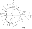
- Figure 1 shows, with reference number 10, the left auricula cordis of a patient.
- an occluder 12 is inserted into the auricula cordis sinistra 10 is used to close the access to the auricula cordis sinistra 10.
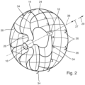
- the occluder 12 comprises a one-piece frame 14. This comprises a proximal tubular section 16 and a cup-shaped distal end section 18.
- the cup-shaped distal end section 18 comprises a circular cylindrical shell section 20 and a base section 22 to form a cup-shaped structure.
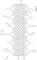
- the occluder has a net-like frame section 24.
- This net-like frame section 24 is Figure 4 Particularly clearly visible in sectioned form.
- the net-like frame section 24 initially has a number of webs 26. These merge into a branching network of webs 25 to form the net structure.
- Diamond-shaped structures 28 are formed in the process. In the distal direction 29, the webs 25 converge again into individual webs 30, which open into the distal end section 18.
- the occluder 12 has a proximal hemisphere 32 and a distal hemisphere 35.
- first anchoring means 34 are provided in the area of the proximal hemisphere 32. These extend along a circular line along the circumference and are hook-shaped with end sections pointing in the proximal direction 27.
- second anchoring means 36 are formed in the area of the distal hemisphere 35. These also extend along a circular line along the circumference, have a rod-like shape and protrude obliquely from the circumferential surface in the proximal direction 27.
- the anchoring means 34, 36 are also formed integrally with the frame 14.
- the frame 14 of the occluder 12 consists of a self-expanding material, for example, a shape memory alloy, in particular a nitinol alloy.
- the expanded shape imprinted on the occluder 12 is spherical (see FIG. Figure 2 ).
- the occluder 12 has a longitudinal axis 38 running in the proximal and distal directions through its center point. This longitudinal axis 38 also extends through the central longitudinal axis of the tubular proximal end section 16 and through the central longitudinal axis of the distal end section 18 (cf. Figure 2 ).
- the proximal hemisphere 32 is completely covered by a biological tissue 40. This biological tissue 40 is in particular designed as a biological membrane.
- the tissue 40 can be the pericardium membrane.
- the tissue 40 has openings such that the first anchoring means 34 protrude through the openings.
- the tissue 40 has an insertion opening for inserting an insertion catheter through the proximal tube section 16 into the occluder 12.
- the elastically flexible tissue 40 can contract such that the insertion opening is closed in a substantially fluid-tight manner, so that overall the tissue 40 closes the proximal hemisphere 32 in a substantially fluid-tight manner and thereby substantially covers the frame 14.
- the fabric is sewn to the frame 14 by means of PTFE threads.
- a number of X-ray markers 38 are placed circumferentially in the region of the proximal hemisphere 32. These markers enable precise positioning of the occluder 12 in the left auricle. Consequently, a surgeon can place the occluder 12 with particularly precise positioning.
- an occluder 12 with comparatively high biocompatibility can be provided. After the occluder 12 has been positioned on the left auricula cordis, the biological tissue 40 can be overgrown by the patient's natural tissue. Due to the biological tissue 40 used, there is a high overall biocompatibility and thus an increased probability of a successful surgical procedure to close the left auricula cordis.
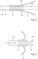
- Figure 5 shows an insertion unit 100.
- This comprises a drive unit 102 and an insertion catheter 104.
- the insertion catheter 104 comprises an inner tube 108 and an outer tube 110.
- the inner tube 108 extends through the outer tube 110.
- the outer tube 110 ends in the distal direction 29 in front of the Inner tube 108.
- the drive unit 102 comprises a housing 114 which can be held in the hand by an operator, in particular a surgeon, and has an overall elongated shape.
- the drive unit 102 comprises an actuating element 116, which is rotatably arranged in the housing 114.
- the actuating element 116 is hollow and has a first drive thread 118 and a second drive thread 120, wherein the first drive thread 118 is proximal to the second drive thread 120 (see Figures 6 and 7 ).
- the actuating element 116 is in particular formed in one piece.
- first transmission element 122 and a second transmission element 124 are arranged in the housing 114. Both transmission elements 122, 124 have a screw-like shape overall.
- the first transmission element 122 has a threaded portion 126 and a head portion 128.
- the second transmission element 124 has a threaded portion 130 and a head portion 132.
- Both transmission elements 122, 124 can, in particular, each be formed integrally.
- the first transmission element 122 is motion-coupled to the inner tube 108, while the second transmission element 124 is motion-coupled to the outer tube 110.
- the head portion 128 of the first transmission element 122 interacts with a Luer connector 134, which is attached to the inner tube 108.
- the Luer connector 134 is detachably arranged on the head portion 128 of the first transmission element 122.
- the head portion 132 of the second transmission element 124 interacts with the outer tube 110 to couple the movement.
- the outer tube 110 is detachably arranged on the head portion 132.
- the insertion unit 100 functions as follows: In order to introduce the occluder 12 into the left auricular cord 10, the introduction catheter 104 is first arranged on the occluder 12 in order to form a system comprising the introduction unit 100 and the occluder 12 in order to bring the occluder 12 up to the left auricular cord 10 and then release the occluder 12.
- the occluder 12 is initially in its self-expanded form and thus has a spherical outer contour (cf. Figure 2 ).
- the outer tube 110 is inserted into the occluder 12 through an insertion opening (not shown) in the biological tissue 40 of the occluder 12 and through the tubular proximal tube section 16.
- the inner tube 108 is then guided through the occluder 12 and the outer tube 110 and arranged on the distal cup-shaped end section 18 of the occluder 12.
- the locking finger-like sections 136 of the inner tube 108 are secured against elastic deformation in the radial direction. secured inside so that the locking fingers 136 come into positive contact with the proximal tubular section 16.
- an operator in particular a surgeon, can take the housing 114 in his hand and rotate the actuating element 116.
- the actuating element 116 is first rotated such that the head-like sections 128, 132 of the two transmission elements 122, 124 are moved towards one another. This moves the distal end 137 of the outer tube 110 and the distal end 138 of the inner tube 108 away from one another. This displaces the distal end 140 of the occluder 12 in the distal direction 29, while the proximal end 142 of the occluder is displaced in the proximal direction 27.
- the occluder 12 is transferred into an insertion position, so that the occluder 12 as a whole assumes a compressed shape in which it has an elongated outer contour with a reduced diameter d compared to the self-expanded shape (cf. Figure 6 ).
- the occluder 12 can be inserted into a blood vessel together with the insertion catheter 104 and then advanced further to its intended position up to the left auricula cordis.
- the position of the occluder 12 can be determined using the X-ray markers 38.
- the occluder 12 should be applied to the left auricula cordis, particularly in the central region, i.e., in the area of the X-ray markers 38.
- the actuating element 116 rotates such that the head-like sections 128, 132 are moved away from each other.
- the inner tube 108 is moved in the proximal direction 27, while the outer tube 110 is moved in the distal direction 29.
- the proximal end 142 of the occluder 12 and the distal end 140 of the occluder 12 are moved toward each other.
- the occluder 12 thereby pushes into its self-expanded shape, so that the proximal end 142 and the distal end 140 of the occluder push toward each other.
- the position of the middle part of the occluder 12 remains unchanged, which is reflected in the Figures 6 and 7 by the center line 144.
- the center line 144 runs through the center of the occluder 12 between the proximal end 142 and the distal end 140 when the latter, as in Figure 6 shown, has reached the destination position.
- the center of the occluder 12 therefore remains true to its position and thus unchanged in its position when the occluder, as shown in Figure 7 shown, is released.
- the outer tube 110 can be pulled off the occluder 12, since the locking finger-like sections 136 can now elastically displace radially inward.
- the occluder 12 can then assume its release position, in which it assumes its self-expanded shape, as shown in Figure 1 shown, or at least pushes it into its self-expanded final shape and can thus tightly close the left auricula cordis.
- the elastically compliant tissue 40 can contract such that the insertion opening (not shown) in the tissue 40 is closed in a substantially fluid-tight manner, so that overall the tissue 40 closes the proximal hemisphere 32 in a substantially or completely fluid-tight manner and thereby substantially or completely covers the frame 14.
- the patient's skin can then grow over the biological tissue 40 so that the left auricula cordis can be permanently and stably closed.
- the insertion catheter 104 can be withdrawn from the occluder 12 particularly easily. This is particularly possible without, or almost without, exerting any torque on the occluder 12. Thus, the risk of the insertion catheter 104 being undesirably displaced from its intended position when withdrawing it from the occluder 12 is reduced.
Landscapes
- Health & Medical Sciences (AREA)
- Surgery (AREA)
- Life Sciences & Earth Sciences (AREA)
- Heart & Thoracic Surgery (AREA)
- Molecular Biology (AREA)
- Vascular Medicine (AREA)
- Engineering & Computer Science (AREA)
- Biomedical Technology (AREA)
- Reproductive Health (AREA)
- Medical Informatics (AREA)
- Nuclear Medicine, Radiotherapy & Molecular Imaging (AREA)
- Animal Behavior & Ethology (AREA)
- General Health & Medical Sciences (AREA)
- Public Health (AREA)
- Veterinary Medicine (AREA)
- Cardiology (AREA)
- Surgical Instruments (AREA)
- Media Introduction/Drainage Providing Device (AREA)
Description
- Die Erfindung betrifft ein System zum Einführen eines selbstexpandierbaren Okkluders in einen Patienten und zum Freisetzen des Okkluders in der auricula cordis sinistra des Patienten.
- Die auriculae atrii oder Vorhofohren sind Ausstülpungen der Vorhöfe des Herzens bei Säugetieren. Das linke Vorhofohr, medizinisch als auricula cordis sinistra (englisch: Left Atrial Appendage (LAA)) bezeichnet, liegt neben dem Strang der Lungenarterie und ist, insbesondere bei Patienten mit Vorhofflimmern, ein häufiger Entstehungsort für Blutgerinnsel, die zu einem Schlaganfall führen können. Die Verhinderung von Thromben in der auricula cordis sinistra stellt daher eine wirksame Schlaganfallprophylaxe bei gefährdeten Patienten dar.
- Für diese Schlaganfallprophylaxe wurden Implantate entwickelt, die in die Ausstülpungen eingesetzt werden und den Zugang beispielsweise über eine Teflonfolie verschließen. In der angelsächsischen Literatur werden diese Implantate als LAA(LAA: Left Atrial Appendage)-Okkluder bezeichnet. Diese Implantate werden in die Ausstülpungen eingesetzt und dort insbesondere mittels Verankerungselementen verankert, so dass sie insbesondere über ihren proximalen Endbereich den Zugang in die Ausstülpungen fluiddicht abschließen. Die Einbringung erfolgt meist über endovaskuläre Techniken, d.h. insbesondere mit einem Einführkatheter, durch den das Implantat an den Einsatzort verbracht wird. Dabei werden die Okkluder insbesondere in volumenreduzierter Form an den Einsatzort verbracht und dort expandiert. Für die Okkluder werden dabei in der Regel selbstexpandierende Materialien verwendet, beispielsweise Formgedächtnislegierungen. Ein derartiger Okkluder ist aus der
WO 2015/079023 A1 vorbekannt. - Zum Einführen eines Okkluders in die auricula cordis sinistra eines Patienten, ist es bekannt, Führungsdraht zu verwenden. Dabei wird der Führungsdraht, wie beispielsweise in der
WO 2015/079023 A1 offenbart, mittels eines Außengewindes an einem Innengewinde des Okkluders festgeschraubt. Sodann wird der Okkluder an seine Bestimmungsposition in den Bereich der auricula cordis sinistra gebracht. Sobald der Okkluder seine selbstexpandierte Form am Bestimmungsort eingenommen hat, kann der Führungsdraht vom Okkluder gelöst werden, indem der Führungsdraht vom Okkluder abgeschraubt wird. Dabei können insbesondere unerwünschte Drehmomente auf den Okkluder einwirken und im schlimmsten Fall sogar zu einem Ablösen des Okkluders von seiner Bestimmungsposition führen. Folglich besteht ein Bedürfnis, diesen Nachteilen abzuhelfen. - Weiterhin besteht ein Bedürfnis, einen Okkluder möglichst einfach in eine Einführlage, die insbesondere eine komprimierte Lage sein kann, verlagern zu können, um in dieser Einführlage den Okkluder an die auricula cordis sinistra heranzuführen.
- Ferner ist aus der
DE 10 2009 020 012 A1 undUS 5 201 757 A bekannt, dass ein Stent durch eine entgegengesetzte Bewegung zweier Elemente eines Katheters in seine selbstexpandierte Form gebracht werden kann. - In der
EP 2 266 465 A1 ist ein Okklusionsinstrument offenbart, wobei beim Einführen keine Anteile über das proximale Ende des Okklusionsinstruments hinausragen. - Aus der
US 2017/0056222 A1 ist eine Handhabungseinheit zum Einsetzen einer Prothese bekannt, wobei zwei Elemente der Handhabungseinheit drehbar zueinander verlagerbar sind, sodass sich ein Außenschlauch und ein Innenschlauch relativ zu einander translatorisch bewegen und aus der sich bildenden Lücke die Form expandiert. - Aus der
WO 2006/036837 A2 ist ein Einführsystem für einen zweiteiligen Okkluder mit einem Außenschlauch und einem innen geführten Draht bekannt, wobei der Außenschlauch an seinem distalen Ende mittels eines Innengewindes mit dem proximalen Ende des Okkluders zusammenwirkt und der innen geführte Draht an seinem distalen Ende mit dem distalen Ende des Okkluders zusammenwirkt. - In der
WO 2017/157316 A1 ist ein Einführsystem für einen faltbaren Okkluder mit einem Außenschlauch und einem Innenschlauch gezeigt, wobei der Außenschlauch mittels eines Innengewindes mit dem proximalen Ende des Okkluders und der Innenschlauch mittels eines Außengewindes mit dem distalen Ende des Okkluders zusammenwirkt. - Die Offenlegungsschrift
WO 2006/036837 A2 offenbart ein System zum Einführen eines Okkluders, der zum Verschließen eines offenen Foramen ovale ausgebildet ist. Ein Innenschlauch einer Einführeinheit des Systems ist mit einem distalen Ende des Okkluders bewegungsgekoppelt. - Die Offenlegungsschrift
US 2007/0135826 A1 offenbart ein System zum Einführen eines Okkluders, der zum Verschließen der auricula cordis sinistra eines Patienten ausgebildet ist. Ein distales Ende eines Außenschlauchs einer Einführeinheit des Systems ist beim Einführen des Okkluders in dem Okkluder angeordnet. - Der vorliegenden Erfindung liegt folglich insgesamt die Aufgabe zugrunde, den bekannten Stand der Technik weiterzubilden.
- Diese Aufgabe wird durch ein System mit den Merkmalen des Anspruchs 1 gelöst.
- Vorgeschlagen wird demnach zunächst ein System zum Einführen eines selbstexpandierbaren Okkluders in einen Patienten und zum Freisetzen des Okkluders in der auricula cordis sinistra des Patienten. Das System umfasst den Okkluder und eine Einführeinheit mit einer Antriebseinheit und mit einem Einführkatheter, welcher einen Außenschlauch und einen sich durch den Außenschlauch erstreckenden Innenschlauch umfasst. Ein proximaler Endbereich des Okkluders ist mit dem Außenschlauch bewegungsgekoppelt, während ein distaler Endbereich des Okkluders mit dem Innenschlauch bewegungsgekoppelt ist, wobei ein distales Ende des Außenschlauchs innerhalb des Okkluders angeordnet ist. Die Antriebseinheit wirkt derart mit dem Innenschlauch und dem Außenschlauch des Okkluders zusammen, dass bei deren Betätigung zum einen der Innenschlauch in distaler bzw. proximaler Richtung bewegbar ist und zum anderen der Außenschlauch in proximaler bzw. distaler Richtung bewegbar ist, sodass das proximale Ende und das distale Ende des Okkluders voneinander weg bzw. aufeinander zu bewegbar sind.
- Durch die Bewegungskopplung des proximalen Endbereichs des Okkluders mit dem Außenschlauch und des distalen Endbereichs des Okkluders mit dem Innenschlauch, können das proximale Ende und das distale Ende des Okkluders voneinander weg bzw. aufeinander zu bewegt werden. Zum Einführen des Okkluders in einen Patienten und zum Hinführen des Okkluders an die auricula cordis sinistra kann folglich zunächst der Innenschlauch in distaler Richtung bewegt werden, während der Außenschlauch in proximaler Richtung bewegt wird. Dadurch können das proximale Ende und das distale Ende des Okkluders voneinander weg bewegt werden, um so den Okkluder in eine Einführlage zu bringen. In dieser Einführlage ist der Okkluder demnach komprimiert angeordnet, so dass dieser eine vergrößerte Länge aber einen verringerten Durchmesser aufweist. Dadurch kann dieser durch insbesondere Blutgefäße hindurch an die auricula cordis sinistra herangeführt werden.
- Zum Freisetzen des Okkluders in der auricula cordis sinistra kann demgegenüber der Innenschlauch in proximaler Richtung bewegt werden, während der Außenschlauch in distaler Richtung bewegt werden kann. Dadurch bewegen sich das proximale Ende und das distale Ende des Okkluders aufeinander zu, wobei der Okkluder insbesondere in seine selbstexpandierte Form strebt. Dabei verringert sich die Länge des Okkluders, während sich sein Durchmesser vergrößert. Im Zuge dieses Freisetzungsvorgangs kommt der Okkluder an der auricula cordis sinistra zur Anlage, um so die auricula cordis sinistra mittels des Okkluders zu verschließen.
- Insgesamt kann auf besonders einfache Art und Weise eine Lageänderung des Okkluders herbeigeführt werden, um so den Okkluder zum einen in eine Einführlage zu überführen, in der der Okkluder besonders einfach an die auricula cordis sinistra eines Patienten herangeführt werden kann, und zum anderen den Okkluder freisetzen zu können, wobei dieser insbesondere in seine selbstexpandierte Form strebt und nach der Freisetzung die auricula cordis sinistra dicht verschließt.
- Eine vorteilhafte Weiterbildung der Erfindung sieht vor, dass der Außenschlauch in distaler Richtung vor dem Innenschlauch endet. Dadurch kann in besonders einfacher Weise eine Bewegungskopplung des proximalen Endbereichs des Okkluders mit dem Außenschlauch und des distalen Endbereichs des Okkluders mit dem Innenschlauch bereitgestellt werden.
- Eine weitere vorteilhafte Ausgestaltung der Erfindung sieht vor, dass der Okkluder einen Rahmen mit einem rohrförmigen proximalen Endbereich umfasst, durch den der Einführkatheter in den Okkluder eingeführt ist. Auf diese Weise kann der Einführkatheter in besonders einfacher Weise in den Okkluder eingeführt werden. Das distale Ende des Außenschlauchs kann dabei in distaler Richtung unmittelbar nach dem rohrförmigen proximalen Endbereich liegen, so dass der Außenschlauch insbesondere mit dem rohrförmigen proximalen Endbereich des Okkluders zur Bewegungskopplung zusammenwirkt. Dabei ist denkbar, dass der Außenschlauch form- bzw. kraftschlüssig mit dem rohrförmigen proximalen Endabschnitt zusammenwirkt. Weiterhin strebt der Okkluder insbesondere in seine selbstexpandierte Form, sodass der Okkluder ausgehend von der Einführlage bei einer Bewegung des Außenschlauchs in distaler Richtung die Bewegung durch das intrinsische Streben in die expandierte Lage unterstützen kann.
- Vorteilhaft ist auch, wenn der Okkluder einen topfförmigen distalen Endbereich umfasst, an dem der Innenschlauch des Einführkatheters angeordnet ist. Der distale Endbereich des Innenschlauchs kann folglich insbesondere in den topfförmigen distalen Endbereich des Okkluders eingeführt sein und darin enden. Der topfförmige distale Endbereich umfasst folglich insbesondere einen kreiszylindrischen Mantelabschnitt und einen Bodenabschnitt. Folglich kann insbesondere in distaler Richtung eine Bewegungskoppplung zwischen dem Innenschlauch und dem distalen Endbereich des Okkluders bereitgestellt werden. Dabei ist denkbar, dass der Innenschlauch im distalen topfförmigen Endbereich form- bzw. kraftschlüssig angeordnet ist. Dadurch kann auch dann eine Bewegungskopplung zwischen Innenschlauch und dem distalen topfförmigen Endbereich des Okkluders bereitgestellt werden, wenn der Innenschlauch in proximaler Richtung bewegt wird. Weiterhin strebt der Okkluder insbesondere in seine selbstexpandierte Form, sodass ausgehend von der Einführlage der Okkluder bei einer Bewegung des Innenschlauchs in proximaler Richtung die Bewegung durch das intrinsische Streben in die expandierte Lage unterstützen kann.
- Besonders bevorzugt ist, wenn der Okkluder zum Einführen in einen Patienten in eine Einführlage überführbar ist, indem ein distales Ende des Innenschlauchs und ein distales Ende des Außenschlauchs relativ zueinander voneinander weg bewegbar sind, sodass das proximale Ende und das distale Ende des Okkluders voneinander weg bewegbar sind. In dieser Einführlage kann der Okkluder insbesondere einen verringerten Durchmesser aufweisen und damit komprimiert sein. Dabei kann der Okkluder eine vergrößerte Länge aufweisen, so dass in der Einführlage der Okkluder im Vergleich zur Freigabelage zwar einen reduzierten Durchmesser, aber eine größere Länge aufweist. In dieser Einführlage kann der Okkluder besonders einfach zur auricula cordis sinistra herangeführt werden.
- Besonders bevorzugt ist dabei, wenn die distalen Enden des Innenschlauchs und des Außenschlauchs zur Freisetzung des Okkluders derart aufeinander zu bewegbar sind, dass das proximale Ende und das distale Ende des Okkluders aufeinander zu bewegbar sind. Dabei ist insbesondere denkbar, dass der Okkluder im Zuge des Freisetzungsvorgangs insbesondere in seine selbstexpandierte Form strebt, sodass ausgehend von der Einführlage der Okkluder bei einer Bewegung des Innenschlauchs in proximaler Richtung bzw. des Außenschlauchs in distaler Richtung der Okkluder intrinsisch in die expandierte Lage strebt.
- Dabei kann vorgesehen sein, dass ein mittlerer Teil des Okkluders zwischen dem proximalen Ende und dem distalen Ende seine Lage während der Freisetzung des Okkluders im Wesentlichen unverändert beibehält. Um den Okkluder an seiner Bestimmungsposition im Bereich der auricula cordis sinistra freizusetzen, werden folglich die distalen Enden des Innenschlauchs und des Außenschlauchs aufeinander zu bewegt, so dass sich das proximale Ende und das distale Ende des Okkluders ebenfalls aufeinander zu bewegen. Dadurch dass der Okkluder insbesondere selbstexpandierbar ausgebildet sein kann, kann insbesondere vorgesehen sein, dass im Zuge des Freisetzungsvorgangs der Okkluder in seine selbstexpandierte Lage strebt. In der Endlage kann der Okkluder dabei an einer Innenseite der auricula cordis sinistra zur Anlage kommen und die auricula cordis sinistra dicht verschließen, um so das Risiko einer Thrombenbildung und eines darauf basierenden Schlaganfallrisikos zu senken. In der Endlage kann der Okkluder entweder seine selbstexpandierte Endform einnehmen. Denkbar ist allerdings auch, dass die Endlage des Okkluders, in der dieser zur dichtenden Anlage an die auricula cordis sinistra gelangt, bereits vor Erreichen der selbstexpandierten Endform erreicht ist und sich der Okkluder sodann nicht weiter verformen kann.
- Denkbar ist, dass der Okkluder eine Mittelachse aufweist, die sich durch den proximalen Endbereich und den distalen Endbereich hindurch erstreckt. Um diese herum kann der Okkluder verlaufen. Der Okkluder kann dabei in der Einführlage entlang dieser Achse einen Mittelpunkt zwischen dem proximalen Ende und dem distalen Ende aufweisen. Wenn nunmehr der Okkluder freigesetzt wird, kann insbesondere vorgesehen sein, dass das proximale Ende und das distale Ende des Okkluders derart aufeinander zu bewegt werden, dass der Mittelpunkt des Okkluders seine Lage beibehält oder im Wesentlichen beibehält. Dadurch kann eine besonders positionsgenaue Anordnung und Freisetzung des Okkluders an der auricula cordis sinistra bereitgestellt werden. In seiner Endlage kann der Okkluder insbesondere eine kugelförmige Außenkontur aufweisen, so dass es sich bei dem Mittelpunkt auch um den Mittelpunkt der kreisförmigen Außenkontur handeln kann.
- Besonders bevorzugt ist weiter, wenn die Antriebseinheit ein erstes Übertragungselement mit einem ersten Übertragungsgewinde, ein zweites Übertragungselement mit einem zweiten Übertragungsgewinde und ein von einer Bedienperson betätigbares Betätigungselement mit einem ersten Antriebsgewinde und einem zweiten Antriebsgewinde aufweist. Dabei ist das erste Übertragungselement mit dem Innenschlauch bewegungsgekoppelt. Das zweite Übertragungselement ist mit dem Außenschlauch bewegungsgekoppelt. Das erste Antriebsgewinde wirkt mit dem ersten Übertragungsgewinde zusammen, während das zweite Antriebsgewinde mit dem zweiten Übertragungsgewinde zusammenwirkt, um die distalen Enden des Außenschlauchs und des Innenschlauchs aufeinander zu bzw. voneinander weg zu bewegen. Auf besonders einfache Art und Weise kann dadurch eine Bewegungskopplung zwischen der Antriebseinheit und dem Außenschlauch bzw. Innenschlauch des Einführkatheters bereitgestellt werden. Dabei können das erste und das zweite Antriebsgewinde einstückig ausgebildet sein. Insbesondere kann das Betätigungselement insgesamt einstückig ausgebildet sein. Bei einer Betätigung des Betätigungselements können folglich zeitgleich die distalen Enden des Außenschlauchs und des Innenschlauchs aufeinander zu bzw. voneinander weg bewegt werden. Dabei kann vorgesehen sein, dass das erste Übertragungsgewinde und das zweite Übertragungsgewinde, sowie das erste und das zweite Antriebsgewinde derart synchron ausgebildet sind, dass bei einer Betätigung des Betätigungselements der Innenschlauch und der Außenschlauch jeweils um dieselbe Distanz in entgegengesetzter Richtung verlagert werden.
- Vorteilhafterweise ist das erste Antriebsgewinde als erstes Innengewinde ausgebildet, welches mit dem als Außengewinde ausgebildeten ersten Übertragungsgewinde zusammenwirkt. Ferner ist vorteilhafterweise das zweite Antriebsgewinde als zweites Innengewinde ausgebildet, das mit dem als Außengewinde ausgebildeten zweiten Übertragungsgewinde zusammenwirkt. Das erste und das zweite Antriebsgewinde können einstückig miteinander ausgebildet sein. Insgesamt kann dadurch eine Bewegungskopplung und eine synchrone Bewegung in entgegengesetzte Richtungen auf besonders einfache Art und Weise realisiert werden.
- Vorzugsweise weist der Außenschlauch an seinem distalen Endbereich wenigstens einen, insbesondere zwei oder mehr, rastfingerartigen Abschnitt auf, der mit dem proximalen Endbereich des Okkluders zur Bewegungskopplung zusammenwirkt. Auf diese Weise kann eine besonders einfache Bewegungskopplung realisiert werden. Dabei kann der rastfingerartige Abschnitt insbesondere mit dem rohrförmigen proximalen Endanschnitt des Okkluders zusammenwirken und diesen insbesondere zur Bewegungskopplung bei einer Bewegung in proximaler Richtung hintergreifen. Der Außenschlauch kann insbesondere einstückig ausgebildet sein.
- Eine besonders bevorzugte Weiterbildung der Erfindung ergibt sich daraus, dass das erste Übertragungselement mit einem am Innenschlauch angeordneten Luer-Anschluss zur Bewegungskopplung mit dem Innenschlauch zusammenwirkt. Am Innenschlauch kann folglich ein Luer-Anschluss angeordnet sein. Dieser kann beispielsweise am ersten Übertragungselement zur Bewegungskopplung angeordnet sein.
- Eine besonders bevorzugte Weiterbildung der Erfindung sieht vor, dass der rastfingerartige Abschnitt formschlüssig am proximalen Endbereich des Okkluders angeordnet ist, wenn der Innenschlauch im Okkluder angeordnet ist. Dabei kann insbesondere vorgesehen sein, dass der rastfingerartige Abschnitt elastisch nachgiebig ausgebildet ist und ausgehend von einer Ruhelage nach dem Einführen des Innenschlauchs durch den Außenschlauch hindurch aus der Ruhelage ausgelenkt wird. Wenn der Innenschlauch folglich durch den Außenschlauch hindurchgeführt ist, kann vorgesehen sein, dass der rastfingerartige Abschnitt nicht nach radial innen ausweichen kann und somit ein stabiler Formschluss zwischen dem proximalen Endbereich des Okkluders und dem rastfingerartigen Abschnitt bereitstellbar ist.
- Besonders bevorzugt ist dabei, wenn zum Entfernen des Einführkatheters vom Okkluder zunächst der Innenschlauch aus dem Okkluders abziehbar ist. Sobald der Innenschlauch aus dem Okkluder durch den Außenschlauch hindurch abgezogen ist, kann sodann vorgesehen sein, dass der Außenschlauch aus dem Okkluder abziehbar ist.
- Folglich kann vorgesehen sein, dass die formschlüssige Verbindung zwischen dem Außenschlauch und dem proximalen Endbereich des Okkluders erst dann aufhebbar ist, wenn der Innenschlauch aus dem Okkluder durch den Außenschlauch hindurch abgezogen ist. Wie oben ausgeführt, können folglich das distale Ende und das proximale Ende des Okkluders zu dessen Freisetzung mittels des Außenschlauchs und des Innenschlauchs aufeinander zu bewegt werden, in dem die distalen Enden des Außenschlauchs und des Innenschlauchs aufeinander zu bewegt werden. Dabei drängt der Okkluder in seine selbstexpandierte Form.
- Sobald dieser Vorgang des Aufeinanderzubewegens des proximalen und distalen Endes des Okkluders abgeschlossen ist, kann der Einführkatheter in besonders einfacher Weise vom Okkluder abgezogen werden, indem zunächst der Innenschlauch aus dem Okkluder durch den Außenschlauch hindurch abgezogen wird. Sodann kann der Außenschlauch aus dem Okkluder abgezogen werden, wobei insbesondere der rastfingerartige Abschnitt am distalen Endbereich des Außenschlauchs elastisch in radialer Richtung nach innen verlagert werden kann, um so den Außenschlauch aus dem insbesondere rohrförmigen proximalen Endabschnitt des Okkluders abzuziehen.
- Durch dieses Vorgehen kann folglich eine unerwünschte Drehmomentübertragung vom Einführkatheter auf den Okkluder im Wesentlichen vollständig oder insbesondere vollständig unterbunden werden. Dadurch kann das Risiko minimiert bzw. ausgeschlossen werden, dass der Okkluder von seiner Bestimmungsposition an der auricula cordis sinistra gelöst wird, wenn der Einführkatheter vom Okkluder entfernt wird. Nach dem Entfernen des Einführkatheters kann der Okkluder vollends in seine selbstexpandierte Form drängen und dabei insbesondere die auricula cordis sinistra vollständig fluiddicht verschließen.
- Vorteilhafterweise weist die Einführeinheit ein Gehäuse auf, das von einer Bedienperson haltbar ist, wobei die Übertragungselemente und das Betätigungselement im bzw. am Gehäuse angeordnet sind. Eine Bedienperson, beispielsweise ein Chirurg, kann folglich das Gehäuse in der Hand halten, so dass das Gehäuse griffartig ausgebildet sein kann. Die Übertragungselemente und/oder das Betätigungselement können im bzw. am Gehäuse angeordnet sein.
- Vorzugsweise ist das Betätigungselement drehbar am Gehäuse angeordnet. Dabei kann das Gehäuse eine Mittellängsachse aufweisen und das Betätigungselement kann um die Mittellängsachse drehbar sein. Das Betätigungselement kann dabei insbesondere einstückig ausgebildet sein und insbesondere hohlzylindrisch mit einem Innengewinde ausgebildet sein.
- Weitere Einzelheiten und vorteilhafte Ausgestaltungen der Erfindung sind der folgenden Beschreibung zu entnehmen, anhand derer die in den Figuren dargestellte Ausführungsform der Erfindung näher beschrieben und erläutert ist. Es zeigen:
- Figur 1
- schematische Draufsicht auf einen an der auricula cordis sinistra angeordneten Okkluder gemäß einer Ausführungsform;
- Figur 2
- schematische perspektivische Darstellung des Okkluders gemäß
Figur 1 ; - Figur 3
- Draufsicht auf eine Hälfte des Okkluders gemäß
Figur 2 ; - Figur 4
- aufgeschnittene schematische Darstellung eines Rahmenabschnitts des Okkluders gemäß
Figur 2 ; - Figur 5
- perspektivische schematische Darstellung einer Einführeinheit gemäß einer Ausführungsform;
- Figur 6
- schematische Querschnittsdarstellung der Einführeinheit gemäß
Figur 1 mit daran angeordnetem Okkluder in Einführlage; - Figur 7
- schematischer Querschnitt der Einführeinheit gemäß
Figur 1 mit daran angeordnetem Okkluder in einer Konfiguration vor dem Entfernen der Einführeinheit vom Okkluder. - Figur 8
- schematischer Querschnitt eines Bereichs um das proximale Ende des Okkluders herum mit daran angeordneter Einführeinheit;
- Figur 9
- Darstellung basierend auf
Figur 8 , wobei der Innenschlauch der Einführeinheit vom Okkluder entfernt ist; und - Figur 10
- Darstellung eines proximalen Bereichs der Einführeinheit mit von der Einführeinheit gelöstem Luer-Anschluss.
-
Figur 1 zeigt mit dem Bezugszeichen 10 zunächst schematisch die auricula cordis sinistra eines Patienten. Zur Reduzierung des Schlaganfallrisikos ist dabei ein Okkluder 12 in die auricula cordis sinistra 10 eingesetzt, um den Zugang zur auricula cordis sinistra 10 zu verschließen. - Der Okkluder 12 umfasst zunächst einen einstückig ausgebildeten Rahmen 14. Dieser umfasst einen proximalen rohrförmigen Abschnitt 16 und einen topfförmigen distalen Endabschnitt 18. Der topfförmige distale Endabschnitt 18 umfasst einen kreiszylindrischen Mantelabschnitt 20 und einen Bodenabschnitt 22, um so eine topfförmige Struktur auszubilden. Zwischen den beiden Endabschnitten 16, 18 weist der Okkluder einen netzartigen Rahmenabschnitt 24 auf. Dieser netzartige Rahmenabschnitt 24 ist in
Figur 4 in aufgeschnittener Form besonders gut ersichtlich. Ausgehend vom proximalen rohrförmigen Endabschnitt 16 weist der netzartige Rahmenabschnitt 24 zunächst eine Anzahl Stege 26 auf. Diese gehen in ein verzweigendes Netzwerk an Stegen 25 über, um so die Netzstruktur auszubilden. Dabei werden rautenförmige Strukturen 28 ausgebildet. In distaler Richtung 29 laufen die Stege 25 wieder zusammen in einzelne Stege 30, die in den distalen Endabschnitt 18 münden. - Im angeordneten Zustand (vgl.
Figur 1 ) weist der Okkluder 12 eine proximale Hemisphäre 32 und eine distale Hemisphäre 35 auf. Im Bereich der proximalen Hemisphäre 32 sind eine Anzahl erste Verankerungsmittel 34 vorgesehen. Diese erstrecken sich entlang einer Kreislinie entlang des Umfangs und sind hakenförmig ausgebildet mit Endabschnitten, die in proximale Richtung 27 weisen. Im Bereich der distalen Hemisphäre 35 sind zweite Verankerungsmittel 36 ausgebildet. Diese erstrecken sich ebenfalls entlang einer Kreislinie entlang des Umfangs, weisen eine stabartige Form auf und ragen schräg von der Umfangsfläche in proximale Richtung 27 ab. Die Verankerungsmittel 34, 36 sind ebenfalls einstückig mit dem Rahmen 14 ausgebildet. - Der Rahmen 14 des Okkluders 12 besteht aus einem selbstexpandierbaren Material, beispielsweise aus einer Formgedächtnislegierung, insbesondere aus einer Nitinol-Legierung. Die dem Okkluder 12 aufgeprägte expandierte Form ist kugelförmig (vgl.
Figur 2 ). Dabei weist der Okkluder 12 eine in proximale bzw. distale Richtung verlaufende Längsachse 38 durch seinen Mittelpunkt auf. Diese Längsachse 38 erstreckt sich auch durch die Mittellängsachse des rohrförmigen proximalen Endabschnitts 16 sowie durch die Mittellängsachse des distalen Endabschnitts 18 (vgl.Figur 2 ). Die proximale Hemisphäre 32 ist vollständig von einem biologischen Gewebe 40 bedeckt. Dieses biologische Gewebe 40 ist insbesondere als biologische Membran ausgebildet. Insbesondere kann es sich um die Pericardium Membran handeln. Das Gewebe 40 weist Öffnungen auf, sodass die ersten Verankerungsmittel 34 durch die Öffnungen hindurchragen. Ferner weist das Gewebe 40 eine Einführöffnung auf, um einen Einführkatheter durch den proximalen Rohrabschnitt 16 in den Okkluder 12 einzuführen. Wenn der Einführkatheter nach der Freisetzung des Okkluders 12 aus dem Okkluder 12 entfernt worden ist, kann das elastisch nachgiebige Gewebe 40 sich so zusammenziehen, dass die Einführöffnung im Wesentlichen fluiddicht verschlossen wird, so dass insgesamt das Gewebe 40 die proximale Hemisphäre 32 im Wesentlichen fluiddicht abschließt und den Rahmen 14 dabei im Wesentlichen abdeckt. Wie schematisch durch chirurgische Fäden 42 angedeutet, ist das Gewebe mittels PTFE-Fäden am Rahmen 14 angenäht. - In der Nähe der Trennebene 44 der proximalen Hemisphäre 32 und der distalen Hemisphäre 35 sind im Bereich der proximalen Hemisphäre 32 über den Umfang eine Anzahl Röntgenmarker 38 platziert. Diese ermöglichen eine exakte Positionierung des Okkluders 12 in der auricula cordis sinistra. Ein Chirurg kann folglich eine besonders positionsgenaue Platzierung des Okkluders 12 durchführen.
- Insgesamt kann durch das Vorsehen des biologischen Gewebes 40 ein Okkluder 12 mit vergleichsweise hoher Biokompatibilität bereitgestellt werden. Dabei kann das biologische Gewebe 40 nach der Anordnung des Okkluders 12 an der auricula cordis sinistra von natürlichem Gewebe des Patienten überwachsen werden. Aufgrund des verwendeten biologischen Gewebes 40 besteht insgesamt eine hohe Biokompatibilität und damit eine erhöhte Erfolgswahrscheinlichkeit, dass ein chirurgischer Eingriff zum Verschließen der auricula cordis sinistra erfolgreich ist.
- Im Folgenden wird ein System zum Einführen des Okkluders 12 in einen Patienten und zum Freisetzen des Okkluders 12 in der auricula cordis sinistra 10 des Patienten gemäß einer Ausführungsform dargelegt:
Figur 5 zeigt insgesamt eine Einführeinheit 100. Diese umfasst zum einen eine Antriebseinheit 102 und zum anderen einen Einführkatheter 104. Der Einführkatheter 104 umfasst einen Innenschlauch 108 und einen Außenschlauch 110. Dabei erstreckt sich der Innenschlauch 108 durch den Außenschlauch 110. Ferner endet der Außenschlauch 110 in distaler Richtung 29 vor dem Innenschlauch 108. Die Antriebseinheit 102 umfasst ein Gehäuse 114, das von einer Bedienperson, insbesondere einem Chirurg, in der Hand gehalten werden kann und insgesamt eine längliche Form aufweist. - Ferner umfasst die Antriebseinheit 102 ein Betätigungselement 116, das drehbar im Gehäuse 114 angeordnet ist. Dabei ist das Betätigungselement 116 hohl ausgebildet mit einem ersten Antriebsgewinde 118 und einem zweiten Antriebsgewinde 120, wobei das erste Antriebsgewinde 118 proximal zum zweiten Antriebsgewinde 120 ist (vgl.
Figuren 6 und7 ). Das Betätigungselement 116 ist insbesondere einstückig ausgebildet. - Im Gehäuse 114 sind ferner ein erstes Übertragungselement 122 und ein zweites Übertragungselement 124 angeordnet. Beide Übertragungselemente 122, 124 weisen insgesamt eine schraubenartige Form auf. Dabei weist das erste Übertragungselement 122 einen Gewindeabschnitt 126 und einen Kopfabschnitt 128 auf. Dementsprechend weist das zweite Übertragungselement 124 einen Gewindeabschnitt 130 und einen Kopfabschnitt 132 auf. Beide Übertragungselemente 122, 124 können insbesondere jeweils einstückig ausgebildet sein. Das erste Übertragungselement 122 ist dabei mit dem Innenschlauch 108 bewegungsgekoppelt, während das zweite Übertragungselement 124 mit dem Außenschlauch 110 bewegungsgekoppelt ist. Der Kopfabschnitt 128 des ersten Übertragungselements 122 wirkt dabei mit einem Luer-Anschluss 134 zusammen, der am Innenschlauch 108 befestigt ist. Dabei ist der Luer-Anschluss 134 am Kopfabschnitt 128 des ersten Übertragungselements 122 lösbar angeordnet.
- Der Kopfabschnitt 132 des zweiten Übertragungselements 124 wirkt mit dem Außenschlauch 110 zur Bewegungskopplung zusammen. Dabei ist der Außenschlauch 110 lösbar am Kopfabschnitt 132 angeordnet.
- Am distalen Ende des Außenschlauchs 110 weist dieser zwei in
Figur 9 besonders deutlich zu erkennende rastfingerartige Endabschnitte 136 auf. Diese sind einstückig mit dem Außenschlauch 110 ausgebildet und elastisch nachgiebig verformbar. Insgesamt ist die Funktionsweise der Einführeinheit 100 sodann wie folgt:
Um den Okkluder 12 in die auricula cordis sinistra 10 einzuführen, wird zunächst der Einführkatheter 104 an dem Okkluder 12 angeordnet, um so ein System aus Einführeinheit 100 und Okkluder 12 auszubilden, um den Okkluder 12 an die auricular cordis sinistra 10 heranzuführen und den Okkluder 12 sodann freizusetzen. - Der Okkluder 12 befindet sich dabei zunächst in seiner selbstexpandierten Form und weist somit eine kugelförmige Außenkontur auf (vgl.
Figur 2 ). Dabei wird der Außenschlauch 110 durch eine nicht gezeigte Einführöffnung im biologischen Gewebe 40 des Okkluders 12 sowie durch den rohrförmigen proximalen Rohrabschnitt 16 in den Okkluder 12 eingeführt. Sodann wird der Innenschlauch 108 durch den Okkluder 12 und den Außenschlauch 110 hindurchgeführt und am distalen topfförmigen Endabschnitt 18 des Okkluders 12 angeordnet. Dabei werden die rastfingerartigen Abschnitte 136 vom Innenschlauch 108 gegen eine elastische Verformung nach radial innen gesichert, so dass die Rastfinger 136 formschlüssig am proximalen rohrförmigen Abschnitt 16 zur Anlage kommen. - Sodann kann von einer Bedienperson, insbesondere von einem Chirurg, das Gehäuse 114 in die Hand genommen werden und das Betätigungselement 116 rotiert werden. Wie in
Figur 6 gezeigt, wird dabei das Betätigungselement 116 zunächst so rotiert, dass die kopfartigen Abschnitte 128, 132 der beiden Übertragungselemente 122, 124 aufeinander zu bewegt werden. Dadurch werden das distale Ende 137 des Außenschlauchs 110 sowie das distale Ende 138 des Innenschlauchs 108 voneinander weg bewegt. Dadurch wird das distale Ende 140 des Okkluders 12 in distaler Richtung 29 verlagert, während das proximale Ende 142 des Okkluders in proximaler Richtung 27 verlagert wird. Insgesamt wird dabei der Okkluder 12 in eine Einführlage überführt, so dass der Okkluder 12 insgesamt eine komprimierte Form einnimmt, in der dieser gegenüber der selbstexpandierten Form eine längliche Außenkontur mit einem verringerten Durchmesser d aufweist (vgl.Figur 6 ). In dieser komprimierten Einführlage kann der Okkluder 12 zusammen mit dem Einführkatheter 104 in ein Blutgefäß eingeführt werden und dann weiter bis zur auricula cordis sinistra an seine Bestimmungsposition herangeführt werden. Die Position des Okkluders 12 kann mittels der Röntgenmarker 38 festgestellt werden. Der Okkluder 12 soll dabei insbesondere im mittleren Bereich, also im Bereich der Röntgenmarker 38, an der auricula cordis sinistra zur Anlage kommen. - Um den Okkluder 12 nunmehr freizusetzen, wird, wie in
Figur 7 gezeigt, das Betätigungselement 116 derart rotiert, sodass die kopfartigen Abschnitte 128, 132 voneinander weg bewegt werden. - Dadurch wird der Innenschlauch 108 in proximaler Richtung 27 bewegt, während der Außenschlauch 110 in distaler Richtung 29 bewegt wird. Im Zuge dieser Relativbewegung werden das proximale Ende 142 des Okkluders 12 und das distale Ende 140 des Okkluders 12 aufeinander zu bewegt. Dadurch wird der Durchmesser d des Okkluders 12 größer. Der Okkluder 12 drängt dabei in seine selbstexpandierte Form, sodass das proximale Ende 142 und das distale Ende 140 des Okkluders aufeinander zu drängen.
- Die Position des mittleren Teils des Okkluders 12 bleibt dabei insbesondere unverändert, was in den
Figuren 6 und7 anhand der Mittellinie 144 dargestellt ist. Die Mittellinie 144 verläuft dabei durch die Mitte des Okkluders 12 zwischen dem proximalen Ende 142 und dem distalen Ende 140, wenn dieser, wie inFigur 6 gezeigt, an der Bestimmungsposition angelangt ist. Die Mitte des Okkluders 12 bleibt also lagegetreu und damit in seiner Lage unverändert, wenn der Okkluder, wie inFigur 7 dargestellt, freigesetzt wird. - In der in
Figur 6 gezeigten Lage ist der Innenschlauch 108 am topfförmigen distalen Endabschnitt 18 des Okkluders 12 kraftschlüssig in proximaler Richtung 27 gehalten. Folglich wird bei einer proximalen Bewegung des Innenschlauchs 108 ebenfalls der distale Endabschnitt 18 des Okkluders 12 in proximaler Richtung 27 bewegt. Wenn der Okkluder 12 dabei in eine Lage, wie inFigur 7 gezeigt, überführt ist, ist dabei die Kraft des Kraftschlusses reduziert, so dass, wie inFigur 10 gezeigt, der Luer-Anschluss 134 vom kopfartigen Abschnitt 128 mit vergleichsweise geringem Kraftaufwand lösbar ist, so dass der Luer-Anschluss 134 und damit der Innenschlauch 108 vom Okkluder 12 durch den Außenschlauch 110 hindurch abziehbar ist. - Daraufhin kann, wie in
Figur 10 gezeigt, der Außenschlauch 110 vom Okkluder 12 abgezogen werden, da sich die rastfingerartigen Abschnitte 136 nunmehr elastisch nach radial innen verlagern können. Sodann kann der Okkluder 12 seine Freigabelage einnehmen, in der dieser seine selbstexpandierte Form, wie inFigur 1 gezeigt, einnehmen kann oder jedenfalls in seine selbstexpandierte Endform drängt und damit die auricula cordis sinistra dicht verschließen kann. Wenn der Einführkatheter nach der Freisetzung des Okkluders 12 aus dem Okkluder 12 entfernt worden ist, kann das elastisch nachgiebige Gewebe 40 sich so zusammenziehen, dass die nicht gezeigte Einführöffnung im Gewebe 40 im Wesentlichen fluiddicht verschlossen wird, so dass insgesamt das Gewebe 40 die proximale Hemisphäre 32 im Wesentlichen oder vollständig fluiddicht abschließt und den Rahmen 14 dabei im Wesentlichen oder vollständig abdeckt. Sodann kann Haut des Patienten über das biologische Gewebe 40 wachsen, sodass die auricula cordis sinistra dauerhaft und stabil verschlossen werden kann. - Aufgrund der vorgeschlagenen Konfiguration kann der Einführkatheter 104 besonders einfach vom Okkluder 12 abgezogen werden. Dies insbesondere ohne, oder nahezu ohne, dass ein Drehmoment auf den Okkluder 12 ausgeübt wird. Somit ist die Gefahr reduziert, dass beim Abziehen des Einführkatheters 104 vom Okkluder 12 dieser von seiner Bestimmungsposition in unerwünschter Weise verlagert wird.
Claims (13)
- System zum Einführen eines selbstexpandierbaren Okkluders (12) in einen Patienten und zum Freisetzen des Okkluders (12) in der auricula cordis sinistra (10) des Patienten, das System umfassend den Okkluder (12) und eine Einführeinheit (100) mit einer Antriebseinheit (102) und mit einem Einführkatheter (104), welcher einen Außenschlauch (110) und einen sich durch den Außenschlauch (110) erstreckenden Innenschlauch (108) umfasst, wobei ein proximaler Endbereich (16) des Okkluders (12) mit dem Außenschlauch (110) bewegungsgekoppelt ist, und wobei ein distaler Endbereich (18) des Okkluders (12) mit dem Innenschlauch (108) bewegungsgekoppelt ist, wobei die Antriebseinheit (102) derart mit dem Innenschlauch (108) und dem Außenschlauch (110) zur Freisetzung des Okkluders (12) zusammenwirkt, dass bei deren Betätigung zum einen der Innenschlauch (108) in distaler bzw. proximaler Richtung bewegbar ist und zum anderen der Außenschlauch (110) in proximaler Richtung (27) bzw. distaler Richtung (29) bewegbar ist, sodass das distale Ende (140) und das proximale Ende (142) des Okkluders (12) voneinander weg bzw. aufeinander zu bewegbar sind,
dadurch gekennzeichnet, dass beim Einführen des Okkluders (12) ein distales Ende (137) des Außenschlauchs (110) innerhalb des Okkluders (12) angeordnet ist, wobei der Außenschlauch (110) an seinem distalen Endbereich wenigstens einen elastisch nachgiebigen, rastfingerartigen Abschnitt (136) aufweist, wobei dieser nur dann mit dem proximalen Endbereich des Okkluders (12) zusammenwirkt, wenn der Innenschlauch (108) im Außenschlauch (110) angeordnet ist, und wobei der rastfingerartige Abschnitt (136) so ausgebildet ist, dass dieser nach dem Einführen des Innenschlauchs (108) durch den Außenschlauch (110) hindurch aus einer Ruhelage ausgelenkt wird und nicht nach radial innen ausweichen kann. - System nach Anspruch 1, wobei der Außenschlauch (110) in distaler Richtung (29) vor dem Innenschlauch (108) endet.
- System nach einem der vorhergehenden Ansprüche, wobei der Okkluder (12) einen Rahmen (14) mit einem rohrförmigen proximalen Endbereich (16) umfasst, durch den der Einführkatheter (104) in den Okkluder (12) eingeführt ist.
- System nach einem der vorhergehenden Ansprüche, wobei der Okkluder (12) einen topfförmigen distalen Endbereich (18) umfasst, an dem der Innenschlauch (108) des Einführkatheters (104) angeordnet ist.
- System nach einem der vorhergehenden Ansprüche, wobei der Okkluder (12) zum Einführen in einen Patienten in eine Einführlage überführbar ist, indem ein distales Ende (138) des Innenschlauchs (108) und das distale Ende (137) des Außenschlauchs (110) relativ zueinander voneinander weg bewegbar sind, sodass das proximale Ende (142) und das distale Ende (140) des Okkluders (12) voneinander weg bewegbar sind.
- System nach Anspruch 5, wobei die distalen Enden (137, 138) des Innenschlauchs (108) und des Außenschlauchs (110) zur Freisetzung des Okkluders (12) derart aufeinander zu bewegbar sind, dass das proximale Ende (142) und das distale Ende (140) des Okkluders (12) aufeinander zu bewegbar sind, vorzugsweise wobei ein mittlerer Teil (144) des Okkluders (12) zwischen dem proximalen Ende (142) und dem distalen Ende (140) seine Lage während der Freisetzung des Okkluders (12) im Wesentlichen unverändert beibehält.
- System nach einem der vorhergehenden Ansprüche, wobei die Antriebseinheit (102) ein erstes Übertragungselement (122) mit einem ersten Übertragungsgewinde (126), ein zweites Übertragungselement (124) mit einem zweiten Übertragungsgewinde (130) und ein von einer Bedienperson betätigbares Betätigungselement (116) mit einem ersten Antriebsgewinde (118) und einem zweiten Antriebsgewinde (120) aufweist, wobei das erste Übertragungselement (122) mit dem Innenschlauch (108) bewegungsgekoppelt ist, und wobei das zweite Übertragungselement mit dem Außenschlauch (110) bewegungsgekoppelt ist, und wobei das erste Antriebsgewinde (118) mit dem ersten Übertragungsgewinde (126) zusammenwirkt und das zweite Antriebsgewinde (120) mit dem zweiten Übertragungsgewinde (130) zusammenwirkt, um die distalen Enden (137, 138) des Außenschlauchs (110) und des Innenschlauchs (108) aufeinander zu bzw. voneinander weg zu bewegen.
- System nach Anspruch 7, wobei das erste Antriebsgewinde (118) als erstes Innengewinde ausgebildet ist, das mit dem als Außengewinde ausgebildeten ersten Übertragungsgewinde (126) zusammenwirkt, und wobei das zweite Antriebsgewinde (120) als zweites Innengewinde ausgebildet ist, das mit dem als Außengewinde ausgebildeten zweiten Übertragungsgewinde (130) zusammenwirkt.
- System nach einem der Ansprüche 7 und 8, wobei das erste Übertragungselement mit einem am Innenschlauch (108) angeordneten Luer-Anschluss (134) zur Bewegungskopplung mit dem Innenschlauch (108) zusammenwirkt.
- System nach einem der vorhergehenden Ansprüche, wobei der rastfingerartige Abschnitt (136) formschlüssig mit dem proximalen Endbereich (16) des Okkluders (12) zusammenwirkt, wenn der Innenschlauch (108) im Okkluder (12) angeordnet ist.
- System nach einem der vorhergehenden Ansprüche, wobei zum Entfernen des Einführkatheters vom Okkluder (12) zunächst der Innenschlauch (108) aus dem Okkluder (12) abziehbar ist, und sodann der Außenschlauch (110) aus dem Okkluder (12) abziehbar ist, sobald der Innenschlauch (108) aus dem Okkluder (12) durch den Außenschlauch (110) hindurch abgezogen ist.
- System nach einem der vorhergehenden Ansprüche 7 bis 9, wobei die Einführeinheit (102) ein Gehäuse (114) aufweist, das von einer Bedienperson haltbar ist, und wobei die Übertragungselemente und das Betätigungselement im bzw. am Gehäuse (114) angeordnet sind.
- System nach Anspruch 7, wobei das Betätigungselement (116) drehbar am Gehäuse angeordnet ist.
Applications Claiming Priority (3)
| Application Number | Priority Date | Filing Date | Title |
|---|---|---|---|
| DE102019100531.0A DE102019100531B4 (de) | 2019-01-10 | 2019-01-10 | Okkludereinführsystem und Einführeinheit |
| PCT/EP2020/050432 WO2020144283A1 (de) | 2019-01-10 | 2020-01-09 | Okkludereinführsystem |
| EP20700468.0A EP3908204A1 (de) | 2019-01-10 | 2020-01-09 | Okkludereinführsystem |
Related Parent Applications (1)
| Application Number | Title | Priority Date | Filing Date |
|---|---|---|---|
| EP20700468.0A Division EP3908204A1 (de) | 2019-01-10 | 2020-01-09 | Okkludereinführsystem |
Publications (4)
| Publication Number | Publication Date |
|---|---|
| EP4101397A2 EP4101397A2 (de) | 2022-12-14 |
| EP4101397A3 EP4101397A3 (de) | 2023-01-11 |
| EP4101397B1 true EP4101397B1 (de) | 2025-06-04 |
| EP4101397C0 EP4101397C0 (de) | 2025-06-04 |
Family
ID=69157858
Family Applications (2)
| Application Number | Title | Priority Date | Filing Date |
|---|---|---|---|
| EP20700468.0A Pending EP3908204A1 (de) | 2019-01-10 | 2020-01-09 | Okkludereinführsystem |
| EP22187317.7A Active EP4101397B1 (de) | 2019-01-10 | 2020-01-09 | Okkludereinführsystem und einführeinheit |
Family Applications Before (1)
| Application Number | Title | Priority Date | Filing Date |
|---|---|---|---|
| EP20700468.0A Pending EP3908204A1 (de) | 2019-01-10 | 2020-01-09 | Okkludereinführsystem |
Country Status (8)
| Country | Link |
|---|---|
| US (2) | US11690630B2 (de) |
| EP (2) | EP3908204A1 (de) |
| JP (2) | JP7342130B2 (de) |
| CN (2) | CN115252037B (de) |
| DE (1) | DE102019100531B4 (de) |
| ES (1) | ES3033758T3 (de) |
| PL (1) | PL4101397T3 (de) |
| WO (1) | WO2020144283A1 (de) |
Families Citing this family (7)
| Publication number | Priority date | Publication date | Assignee | Title |
|---|---|---|---|---|
| US11399842B2 (en) | 2013-03-13 | 2022-08-02 | Conformal Medical, Inc. | Devices and methods for excluding the left atrial appendage |
| US9943315B2 (en) | 2013-03-13 | 2018-04-17 | Conformal Medical, Inc. | Devices and methods for excluding the left atrial appendage |
| US11426172B2 (en) | 2016-10-27 | 2022-08-30 | Conformal Medical, Inc. | Devices and methods for excluding the left atrial appendage |
| WO2018081466A2 (en) | 2016-10-27 | 2018-05-03 | Conformal Medical, Inc. | Devices and methods for excluding the left atrial appendage |
| WO2020163507A1 (en) | 2019-02-08 | 2020-08-13 | Conformal Medical, Inc. | Devices and methods for excluding the left atrial appendage |
| US12144508B2 (en) | 2019-02-08 | 2024-11-19 | Conformal Medical, Inc. | Devices and methods for excluding the left atrial appendage |
| CN116849729A (zh) * | 2023-06-28 | 2023-10-10 | 上海形状记忆合金材料有限公司 | 封堵器输送装置及封堵器的输送方法 |
Family Cites Families (24)
| Publication number | Priority date | Publication date | Assignee | Title |
|---|---|---|---|---|
| US5201757A (en) * | 1992-04-03 | 1993-04-13 | Schneider (Usa) Inc. | Medial region deployment of radially self-expanding stents |
| US6689150B1 (en) * | 1999-10-27 | 2004-02-10 | Atritech, Inc. | Filter apparatus for ostium of left atrial appendage |
| US7735493B2 (en) * | 2003-08-15 | 2010-06-15 | Atritech, Inc. | System and method for delivering a left atrial appendage containment device |
| WO2006036837A2 (en) | 2004-09-24 | 2006-04-06 | Nmt Medical, Inc. | Occluder device double securement system for delivery/recovery of such occluder device |
| US20070135826A1 (en) | 2005-12-01 | 2007-06-14 | Steve Zaver | Method and apparatus for delivering an implant without bias to a left atrial appendage |
| WO2007073566A1 (en) * | 2005-12-22 | 2007-06-28 | Nmt Medical, Inc. | Catch members for occluder devices |
| US8518098B2 (en) * | 2006-02-21 | 2013-08-27 | Cook Medical Technologies Llc | Split sheath deployment system |
| DE102006013770A1 (de) * | 2006-03-24 | 2007-09-27 | Occlutech Gmbh | Occlusionsinstrument und Verfahren zu dessen Herstellung |
| EP1891902A1 (de) * | 2006-08-22 | 2008-02-27 | Carag AG | Okklusionsanordnung |
| US8715319B2 (en) * | 2007-09-28 | 2014-05-06 | W.L. Gore & Associates, Inc. | Catch member for septal occluder with adjustable-length center joint |
| US8197498B2 (en) | 2008-11-06 | 2012-06-12 | Trinitas Ventures Ltd. | Gastric bypass devices and procedures |
| DE102009020012A1 (de) | 2009-05-05 | 2010-11-11 | Acandis Gmbh & Co. Kg | Vorrichtung zum Freisetzen eines selbstexpandierbaren medizinischen Funktionselements |
| US20120185031A1 (en) | 2011-01-19 | 2012-07-19 | Michael Ryan | Rotary and linear handle mechanism for constrained stent delivery system |
| EP4324409A3 (de) | 2011-11-01 | 2024-03-13 | Coherex Medical, Inc. | Medizinische vorrichtung zur modifizierung des linken herzohrs sowie zugehörige systeme und verfahren |
| US8951243B2 (en) * | 2011-12-03 | 2015-02-10 | Boston Scientific Scimed, Inc. | Medical device handle |
| WO2013128461A1 (en) * | 2012-02-29 | 2013-09-06 | Cardiapex Ltd. | Minimally invasive surgical techniques |
| CN102895008B (zh) | 2012-09-28 | 2015-12-02 | 上海形状记忆合金材料有限公司 | 医用封堵器及其输送系统 |
| US9539130B2 (en) | 2012-10-29 | 2017-01-10 | Cook Medical Technologies Llc | Low profile stepped delivery system |
| DE102013019890A1 (de) | 2013-11-28 | 2015-05-28 | Bentley Innomed Gmbh | Medizinisches Implantat |
| CN203943701U (zh) * | 2014-07-07 | 2014-11-19 | 宁波健世生物科技有限公司 | 一种新型的可拆卸的输送系统 |
| US10172733B2 (en) * | 2015-09-01 | 2019-01-08 | Cook Medical Technologies Llc | Modular handle for a prosthesis delivery device |
| EP3416596B1 (de) * | 2016-02-19 | 2020-04-01 | Joline GmbH & Co. KG | Stent-delivery-system |
| WO2017157316A1 (zh) | 2016-03-18 | 2017-09-21 | 上海微创医疗器械(集团)有限公司 | 左心耳封堵器及其输送系统 |
| WO2018176064A2 (en) | 2017-03-24 | 2018-09-27 | Metactive Medical, Inc. | Medical devices comprising detachable balloons and methods of manufacturing and use |
-
2019
- 2019-01-10 DE DE102019100531.0A patent/DE102019100531B4/de active Active
-
2020
- 2020-01-09 CN CN202210953573.0A patent/CN115252037B/zh active Active
- 2020-01-09 ES ES22187317T patent/ES3033758T3/es active Active
- 2020-01-09 CN CN202080008746.0A patent/CN113286550B/zh active Active
- 2020-01-09 EP EP20700468.0A patent/EP3908204A1/de active Pending
- 2020-01-09 PL PL22187317.7T patent/PL4101397T3/pl unknown
- 2020-01-09 WO PCT/EP2020/050432 patent/WO2020144283A1/de not_active Ceased
- 2020-01-09 EP EP22187317.7A patent/EP4101397B1/de active Active
- 2020-01-09 JP JP2021538773A patent/JP7342130B2/ja active Active
- 2020-01-09 US US17/422,000 patent/US11690630B2/en active Active
-
2022
- 2022-08-17 US US17/889,948 patent/US11890019B2/en active Active
- 2022-08-30 JP JP2022136468A patent/JP7367150B2/ja active Active
Also Published As
| Publication number | Publication date |
|---|---|
| EP3908204A1 (de) | 2021-11-17 |
| CN115252037A (zh) | 2022-11-01 |
| DE102019100531A1 (de) | 2020-07-16 |
| JP2022529761A (ja) | 2022-06-24 |
| CN115252037B (zh) | 2023-10-31 |
| EP4101397A2 (de) | 2022-12-14 |
| BR112021013203A2 (pt) | 2021-09-28 |
| EP4101397A3 (de) | 2023-01-11 |
| US20220387043A1 (en) | 2022-12-08 |
| CN113286550B (zh) | 2024-06-11 |
| PL4101397T3 (pl) | 2025-09-22 |
| WO2020144283A1 (de) | 2020-07-16 |
| DE102019100531B4 (de) | 2021-08-19 |
| ES3033758T3 (en) | 2025-08-07 |
| US11690630B2 (en) | 2023-07-04 |
| US11890019B2 (en) | 2024-02-06 |
| US20220096093A1 (en) | 2022-03-31 |
| JP2022164758A (ja) | 2022-10-27 |
| JP7342130B2 (ja) | 2023-09-11 |
| JP7367150B2 (ja) | 2023-10-23 |
| EP4101397C0 (de) | 2025-06-04 |
| CN113286550A (zh) | 2021-08-20 |
Similar Documents
| Publication | Publication Date | Title |
|---|---|---|
| EP4101397B1 (de) | Okkludereinführsystem und einführeinheit | |
| DE60224851T2 (de) | Intravaskuläres Filtersystem | |
| EP3213717B1 (de) | Einführkatheter und katheteranordnung | |
| US11291452B2 (en) | Medical device deployment system | |
| EP4215128B1 (de) | Okkluder, system aus okkluder und einführkatheter und verfahren zur bereitstellung des systems | |
| DE69617912T2 (de) | Ausbreitbares intraluminales gewebe zum ausbessern eines aneurysmas | |
| EP3897454B1 (de) | Vorrichtung zum zuführen und setzen eines implantats in ein blutgefäss | |
| EP2884946B1 (de) | Implantierbare einrichtung zur verwendung im menschlichen und/oder tierischen körper zum ersatz einer organklappe | |
| EP2786726B1 (de) | Katheter für die transvaskuläre Implantation von Herzklappenprothesen | |
| DE69322382T2 (de) | Mittelzonenentfaltung von radialen,selbstexpandierenden dilatatoren | |
| DE60015841T2 (de) | Verschlussvorrichtung | |
| EP2710985A2 (de) | Implantat, System aus einem Implantat und einem Katheter sowie Verfahren zur Herstellung eines solchen Systems | |
| EP4009918B1 (de) | Implantat mit einer dreidimensionalen struktur | |
| EP1539030A2 (de) | Extraktionsvorrichtung | |
| EP3073935B1 (de) | System zum verbinden eines medizinischen implantats mit einer einführhilfe | |
| EP4251098A1 (de) | MEDIZINISCHES SET ZUR BEHANDLUNG VON BLUTGEFÄßERKRANKUNGEN | |
| DE102013104565B3 (de) | Pusher-Baugruppe für ein Einführsystem für ein selbstexpandierendes Gefäßimplantat sowie ein entsprechendes Einführsystem | |
| EP3781088B1 (de) | Vorrichtung zur einbringung von implantaten | |
| EP3473212A1 (de) | System aus katheter und herzklappenprothese | |
| DE112009005410T5 (de) | Katheter mit Notauslöser |
Legal Events
| Date | Code | Title | Description |
|---|---|---|---|
| PUAI | Public reference made under article 153(3) epc to a published international application that has entered the european phase |
Free format text: ORIGINAL CODE: 0009012 |
|
| STAA | Information on the status of an ep patent application or granted ep patent |
Free format text: STATUS: THE APPLICATION HAS BEEN PUBLISHED |
|
| PUAL | Search report despatched |
Free format text: ORIGINAL CODE: 0009013 |
|
| AC | Divisional application: reference to earlier application |
Ref document number: 3908204 Country of ref document: EP Kind code of ref document: P |
|
| AK | Designated contracting states |
Kind code of ref document: A2 Designated state(s): AL AT BE BG CH CY CZ DE DK EE ES FI FR GB GR HR HU IE IS IT LI LT LU LV MC MK MT NL NO PL PT RO RS SE SI SK SM TR |
|
| AK | Designated contracting states |
Kind code of ref document: A3 Designated state(s): AL AT BE BG CH CY CZ DE DK EE ES FI FR GB GR HR HU IE IS IT LI LT LU LV MC MK MT NL NO PL PT RO RS SE SI SK SM TR |
|
| RIC1 | Information provided on ipc code assigned before grant |
Ipc: A61B 17/12 20060101AFI20221202BHEP |
|
| STAA | Information on the status of an ep patent application or granted ep patent |
Free format text: STATUS: REQUEST FOR EXAMINATION WAS MADE |
|
| 17P | Request for examination filed |
Effective date: 20230615 |
|
| RBV | Designated contracting states (corrected) |
Designated state(s): AL AT BE BG CH CY CZ DE DK EE ES FI FR GB GR HR HU IE IS IT LI LT LU LV MC MK MT NL NO PL PT RO RS SE SI SK SM TR |
|
| GRAP | Despatch of communication of intention to grant a patent |
Free format text: ORIGINAL CODE: EPIDOSNIGR1 |
|
| STAA | Information on the status of an ep patent application or granted ep patent |
Free format text: STATUS: GRANT OF PATENT IS INTENDED |
|
| INTG | Intention to grant announced |
Effective date: 20250107 |
|
| GRAS | Grant fee paid |
Free format text: ORIGINAL CODE: EPIDOSNIGR3 |
|
| GRAA | (expected) grant |
Free format text: ORIGINAL CODE: 0009210 |
|
| STAA | Information on the status of an ep patent application or granted ep patent |
Free format text: STATUS: THE PATENT HAS BEEN GRANTED |
|
| AC | Divisional application: reference to earlier application |
Ref document number: 3908204 Country of ref document: EP Kind code of ref document: P |
|
| AK | Designated contracting states |
Kind code of ref document: B1 Designated state(s): AL AT BE BG CH CY CZ DE DK EE ES FI FR GB GR HR HU IE IS IT LI LT LU LV MC MK MT NL NO PL PT RO RS SE SI SK SM TR |
|
| REG | Reference to a national code |
Ref country code: GB Ref legal event code: FG4D Free format text: NOT ENGLISH |
|
| REG | Reference to a national code |
Ref country code: CH Ref legal event code: EP |
|
| REG | Reference to a national code |
Ref country code: DE Ref legal event code: R096 Ref document number: 502020011187 Country of ref document: DE |
|
| REG | Reference to a national code |
Ref country code: IE Ref legal event code: FG4D Free format text: LANGUAGE OF EP DOCUMENT: GERMAN |
|
| U01 | Request for unitary effect filed |
Effective date: 20250612 |
|
| U07 | Unitary effect registered |
Designated state(s): AT BE BG DE DK EE FI FR IT LT LU LV MT NL PT RO SE SI Effective date: 20250623 |
|
| REG | Reference to a national code |
Ref country code: ES Ref legal event code: FG2A Ref document number: 3033758 Country of ref document: ES Kind code of ref document: T3 Effective date: 20250807 |
|
| PG25 | Lapsed in a contracting state [announced via postgrant information from national office to epo] |
Ref country code: GR Free format text: LAPSE BECAUSE OF FAILURE TO SUBMIT A TRANSLATION OF THE DESCRIPTION OR TO PAY THE FEE WITHIN THE PRESCRIBED TIME-LIMIT Effective date: 20250905 Ref country code: NO Free format text: LAPSE BECAUSE OF FAILURE TO SUBMIT A TRANSLATION OF THE DESCRIPTION OR TO PAY THE FEE WITHIN THE PRESCRIBED TIME-LIMIT Effective date: 20250904 |
|
| PG25 | Lapsed in a contracting state [announced via postgrant information from national office to epo] |
Ref country code: HR Free format text: LAPSE BECAUSE OF FAILURE TO SUBMIT A TRANSLATION OF THE DESCRIPTION OR TO PAY THE FEE WITHIN THE PRESCRIBED TIME-LIMIT Effective date: 20250604 |
|
| PG25 | Lapsed in a contracting state [announced via postgrant information from national office to epo] |
Ref country code: RS Free format text: LAPSE BECAUSE OF FAILURE TO SUBMIT A TRANSLATION OF THE DESCRIPTION OR TO PAY THE FEE WITHIN THE PRESCRIBED TIME-LIMIT Effective date: 20250904 |
|
| PG25 | Lapsed in a contracting state [announced via postgrant information from national office to epo] |
Ref country code: IS Free format text: LAPSE BECAUSE OF FAILURE TO SUBMIT A TRANSLATION OF THE DESCRIPTION OR TO PAY THE FEE WITHIN THE PRESCRIBED TIME-LIMIT Effective date: 20251004 |
|
| PG25 | Lapsed in a contracting state [announced via postgrant information from national office to epo] |
Ref country code: SM Free format text: LAPSE BECAUSE OF FAILURE TO SUBMIT A TRANSLATION OF THE DESCRIPTION OR TO PAY THE FEE WITHIN THE PRESCRIBED TIME-LIMIT Effective date: 20250604 |
|
| PG25 | Lapsed in a contracting state [announced via postgrant information from national office to epo] |
Ref country code: CZ Free format text: LAPSE BECAUSE OF FAILURE TO SUBMIT A TRANSLATION OF THE DESCRIPTION OR TO PAY THE FEE WITHIN THE PRESCRIBED TIME-LIMIT Effective date: 20250604 |
|
| PGFP | Annual fee paid to national office [announced via postgrant information from national office to epo] |
Ref country code: PL Payment date: 20251126 Year of fee payment: 7 |
|
| PG25 | Lapsed in a contracting state [announced via postgrant information from national office to epo] |
Ref country code: SK Free format text: LAPSE BECAUSE OF FAILURE TO SUBMIT A TRANSLATION OF THE DESCRIPTION OR TO PAY THE FEE WITHIN THE PRESCRIBED TIME-LIMIT Effective date: 20250604 |
|
| REG | Reference to a national code |
Ref country code: CH Ref legal event code: U11 Free format text: ST27 STATUS EVENT CODE: U-0-0-U10-U11 (AS PROVIDED BY THE NATIONAL OFFICE) Effective date: 20260201 |
|
| U20 | Renewal fee for the european patent with unitary effect paid |
Year of fee payment: 7 Effective date: 20260119 |
|
| PGFP | Annual fee paid to national office [announced via postgrant information from national office to epo] |
Ref country code: GB Payment date: 20260113 Year of fee payment: 7 |
|
| PGFP | Annual fee paid to national office [announced via postgrant information from national office to epo] |
Ref country code: ES Payment date: 20260217 Year of fee payment: 7 |
|
| PLBE | No opposition filed within time limit |
Free format text: ORIGINAL CODE: 0009261 |
|
| STAA | Information on the status of an ep patent application or granted ep patent |
Free format text: STATUS: NO OPPOSITION FILED WITHIN TIME LIMIT |
|
| PGFP | Annual fee paid to national office [announced via postgrant information from national office to epo] |
Ref country code: IE Payment date: 20260121 Year of fee payment: 7 |
|
| REG | Reference to a national code |
Ref country code: CH Ref legal event code: L10 Free format text: ST27 STATUS EVENT CODE: U-0-0-L10-L00 (AS PROVIDED BY THE NATIONAL OFFICE) Effective date: 20260416 |
|
| PGFP | Annual fee paid to national office [announced via postgrant information from national office to epo] |
Ref country code: CH Payment date: 20260201 Year of fee payment: 7 |