EP4101331B1 - Knöchelschutz - Google Patents
Knöchelschutz Download PDFInfo
- Publication number
- EP4101331B1 EP4101331B1 EP22020263.4A EP22020263A EP4101331B1 EP 4101331 B1 EP4101331 B1 EP 4101331B1 EP 22020263 A EP22020263 A EP 22020263A EP 4101331 B1 EP4101331 B1 EP 4101331B1
- Authority
- EP
- European Patent Office
- Prior art keywords
- person
- main part
- ankle
- protection device
- wall
- Prior art date
- Legal status (The legal status is an assumption and is not a legal conclusion. Google has not performed a legal analysis and makes no representation as to the accuracy of the status listed.)
- Active
Links
Images
Classifications
-
- A—HUMAN NECESSITIES
- A61—MEDICAL OR VETERINARY SCIENCE; HYGIENE
- A61F—FILTERS IMPLANTABLE INTO BLOOD VESSELS; PROSTHESES; DEVICES PROVIDING PATENCY TO, OR PREVENTING COLLAPSING OF, TUBULAR STRUCTURES OF THE BODY, e.g. STENTS; ORTHOPAEDIC, NURSING OR CONTRACEPTIVE DEVICES; FOMENTATION; TREATMENT OR PROTECTION OF EYES OR EARS; BANDAGES, DRESSINGS OR ABSORBENT PADS; FIRST-AID KITS
- A61F5/00—Orthopaedic methods or devices for non-surgical treatment of bones or joints; Nursing devices ; Anti-rape devices
- A61F5/01—Orthopaedic devices, e.g. long-term immobilising or pressure directing devices for treating broken or deformed bones such as splints, casts or braces
- A61F5/0102—Orthopaedic devices, e.g. long-term immobilising or pressure directing devices for treating broken or deformed bones such as splints, casts or braces specially adapted for correcting deformities of the limbs or for supporting them; Ortheses, e.g. with articulations
- A61F5/0104—Orthopaedic devices, e.g. long-term immobilising or pressure directing devices for treating broken or deformed bones such as splints, casts or braces specially adapted for correcting deformities of the limbs or for supporting them; Ortheses, e.g. with articulations without articulation
- A61F5/0111—Orthopaedic devices, e.g. long-term immobilising or pressure directing devices for treating broken or deformed bones such as splints, casts or braces specially adapted for correcting deformities of the limbs or for supporting them; Ortheses, e.g. with articulations without articulation for the feet or ankles
-
- A—HUMAN NECESSITIES
- A43—FOOTWEAR
- A43B—CHARACTERISTIC FEATURES OF FOOTWEAR; PARTS OF FOOTWEAR
- A43B7/00—Footwear with health or hygienic arrangements
- A43B7/14—Footwear with health or hygienic arrangements with foot-supporting parts
- A43B7/18—Joint supports, e.g. instep supports
- A43B7/20—Ankle-joint supports or holders
Definitions
- the present invention relates to a device for protecting a person's ankle, more precisely the malleolus.
- This type of device can be used mainly by users of motorized vehicles such as motorcycles, mopeds, mopeds, scooters, three-wheelers or even quads.
- the ankles and particularly the malleoli of users of two-wheeled and/or three-wheeled motorized vehicles are organs often affected during an impact or even a fall.
- the malleolus a term designating one of the two bony tuberosities located at the level of a person's ankle joint, appearing in the form of a projection under the skin on each side of it, can be subject to abrasion with raw scratching, cracks and sometimes even fractures.
- the protection of these organs and therefore the use of protective equipment for the ankle and more specifically the malleolus is a necessity.
- the main ankle protection equipment known, particularly for motorcyclists is motorcycle boots and/or shoes.
- Such equipment has a certain rigidity and has several reinforcements arranged at sensitive points such as, for example, the malleolus.
- Some users do not wish to wear such equipment outside of their motorized journey.
- Such motorcycle shoes and/or boots are often heavy, imposing and not always to the taste of the user, particularly depending on their clothing.
- many users prioritize the style, comfort and ease of wearing city shoes above all, whether for their working day and/or for their leisure activities.
- the transport and storage of spare shoes and boots and/or motorcycle shoes is not practical, it is often made the choice not to wear suitable motorcycle shoes or boots because they are too often considered as bulky, which is an unreasonable choice considering the risks involved.
- WO 2014/176368 A1 discloses an ankle protection device according to the prior art.
- the present invention therefore aims to remedy the aforementioned drawbacks, in particular to propose a device for protecting the ankle and more precisely the malleoli against shocks and abrasion which may result from falls on a motorcycle for example.
- Said device is designed to compensate for the lack of protection of street shoes while being compact and therefore easy to store in a bag or pocket, for example.
- the user has the possibility of keeping his street shoes on during his day and simply adds said protective device to his ankles when he wishes to travel with his motorized vehicle.
- the invention discloses a device for protecting a person's ankle according to claim 1.
- Said device comprises a main part, two reinforcements, closure means and a rigid element.
- Said main part is composed of an anti-abrasion material enveloping the ankle and has a rear part placed on the back of the ankle, at the level of the person's Achilles tendon, a front part placed on the front of the ankle, at the level of the person's instep, an interior wall intended to be in contact with the ankle and an exterior wall.
- the two reinforcements are fixed to the interior wall of said main part at the level of the malleoli of the person's ankle.
- the closing means are fixed to the exterior wall of the main part making it possible to hold and tighten said device against the ankle.
- the rigid element has two parts connected together by an elbow, an upper part being fixed to the rear part of the main part and a lower part being intended to be positioned under the heel of a shoe of the person.
- the material constituting the main part may be oily leather.
- the closure means can correspond to straps and buckles fixed on either side of the exterior wall of the main part.
- the straps may be mainly made of leather and may include a zone of hook-and-loop material.
- the reinforcements consist of thermoplastic polyurethane, acrylonitrile butadiene styrene or polypropylene.
- said device may further comprise a high-density reinforcing plate fixed to the interior wall of the main part making it possible to hold the two reinforcements in position on the interior wall of the main part.
- the rigid element can be fixed to the rear part of the main part via height-adjustable fixing means.
- the height-adjustable fixing means may comprise a first element located on the upper part of the rigid element and a second element located on the rear part of the main part. Said first and second elements will thus cooperate with each other to hold the first element on the second element in several positions.
- the first element is an oblong hole and the second element consists of threaded inserts held at the rear part of the main part by the high density reinforcing part in order to receive screws.
- the oblong hole for its part, allows the screws to pass through and ensures adjustment to the desired height.
- said device for protecting a person's ankle may also include a foam positioned on the interior wall of said main part. Said foam conforms to the shape of the person's ankle.
- said device may also include a sock enveloping the front of the foot.
- Said sock and the main part are each provided with press studs in order to fix said sock to said device.
- the snaps on said sock are intended to cooperate with the snaps on the main piece.
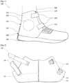
- FIG.1 An example of an ankle protection device 100 for a person, in accordance with the invention, is shown in [ Fig.1 ].
- Said ankle protection device 100 is composed of a main part 110 enveloping the ankle 200 of the person, two reinforcements 120 fixed to the main part 110, closing means making it possible to tighten said device 100 against the ankle 200.
- said device 100 in order to allow good support of said device 100 against the ankle 200 and therefore to ensure effective protection of the malleoli, said device 100, according to the invention, comprises a rigid element 150 fixed to the main part 110 and supported under the heel of a person's shoe.
- the main part 110 is dimensioned to be positioned above the person's shoe in order to wrap the ankle 200. To do this, it has a rear part 111 which is placed on the back of the ankle 200 located at the level of the person's Achilles tendon and a front part 112 which is placed on the front of the ankle 200 located at the level of the person's instep.
- said main part 110 has an interior wall 113 which is intended to come into contact with the ankle 200 of the person and an exterior wall 114 which is opposite the interior wall 113 and therefore potentially subject to external attacks such as as abrasion, shocks and impacts.
- said main part 110 is composed of an anti-abrasion material.
- an anti-abrasion material may be oily leather.
- oiled leather is a particularly robust leather and very suitable for difficult conditions of use. As such, it is today very often used for technical work and/or hiking shoes, for example.
- a fatty leather between 1.6 and 2.2 millimeters thick, preferably 2 millimeters, is preferred, in order to have sufficient anti-abrasion resistance for the desired protection and a advantageous elasticity to be able to work the leather and allow the manufacture of said main part 110.
- the invention is not limited to this choice of material for said main part, those skilled in the art can use any other material compatible with the use made of it within the invention, namely a material combining resistance to abrasion and a certain elasticity allowing easy shaping.
- technical fabrics can be used such as aramid-based fabrics or fabrics combining nylon and elastane or even polyamide-based textiles.
- such a main part 110 can be formed by two parts sewn together.
- the sewing zone 115 is located at the level of the rear part 111 of said main part 110 so that said rear part 111 corresponds and follows the curve of the rear of the ankle 200 of the person.
- the visible seam 115 on the exterior wall 114 can be covered with a strip sewn over the entire length of the rear part 111 and on either side of said seam 115 in order to hide said seam 115 for aesthetic considerations but also in order to consolidate it.
- This sewn band can be made of twill, which increases resistance to wear.
- the main part 110 can be made in a single part which is shaped by forming processes depending on the material constituting the main part 110.
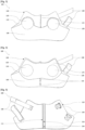
- the two reinforcements 120 are fixed to the interior wall 113 of said main part at the level of each malleolus of the ankle 200 of the person in order to ensure protection during impacts and to reduce heating due to abrasion .
- the two reinforcements 120 can be fixed to the interior wall 113 by sewing, by insertion into pockets provided for this purpose or any other means allowing said reinforcements 120 to be maintained within said device 100 and at the level of each malleolus.
- Such reinforcements 120 can be concave shells so that said reinforcements 120 correctly encompass each of the person's malleolus. Said shells will be sized so that the reinforcements 120 can adapt to a very large number of malleolus regardless of the person's build.
- such reinforcements 120 can be made up, for example, of thermoplastic polyurethane, conventionally used as a material in motorcycle boots.
- the invention is not limited to this choice of material for the reinforcements 120; those skilled in the art may use any other material compatible with the use made of it within the invention.
- said device 100 may also comprise a high density reinforcing plate 160.
- this high density reinforcement plate 160 is fixed, for example sewn, to the interior wall 113 of said main part 110.
- said reinforcements 120 fixed to the interior wall 113 can be fixed using said reinforcement plate 160, which makes it possible to maintain said reinforcements 120 in position at the level of each of the malleoli.
- the reinforcements 120 can be enclosed between the interior wall 113 of the part main 111 and said high density reinforcement plate 160. Said reinforcements 120 can even, for example, be sewn to said high density reinforcement plate 160 or inserted into said high density reinforcement plate 160.
- a such high density reinforcing plate 160 may be Texon® , consisting of non-woven fibrous materials bonded by an elastomer, preferably having a thickness of between 1 and 1.5 millimeters.
- the invention is not limited to the choice of the material of said reinforcing plate 160 or even to its thickness.
- the closing means can be straps 130 and buckles 140 fixed on either side of the outer wall 114 of said main part 110.
- Each strap 130 is intended to cooperate with a buckle 140 in order to hold and tighten the device 100 against the ankle 200.
- said device 100 may comprise two pairs of straps 130 and buckles 140, one pair being able to be positioned at the level of the tibia and another pair at the level of the instep.
- fixing the straps 130 and/or the buckles 140 to the exterior wall 140 it is possible to use a fixing system by sewing, by gluing or even by screwing, the invention not being limited to the choice of the system for fixing the straps 130 and buckles 140.
- the straps 130 correspond to straps made of leather or anti-abrasion material, having an area of Velcro® type self-gripping material and the buckles 140 correspond to a ring, a rectangle or other, presenting a crosspiece intended to receive one or more straps.
- Each strap, corresponding to one of the straps 130, is thus introduced into the crosspiece of one of the loops 140 and comes to fold back on itself: adhesion being ensured by the self-gripping zone of the strap 130.
- Said straps will be dimensioned so that said device 100 can adapt to a wide range of ankles. For example, it may be considered to use straps 200 millimeters long and 25 millimeters wide. Alternatively, any other closing means compatible with the use made of it in the invention, such as clipping or lace closing means or even close to those used for ski boots, can be used instead. and places straps 130 and buckles 140.
- the rigid element 150 is fixed to the exterior wall 114 of the main part 110 and is placed under the heel of the person's shoe.
- said rigid element 150 has an upper part 151 fixed to the rear part 111 of the main part 110 and a lower part 152 intended to be positioned under the heel of the person's shoe.
- the upper part 151 having a substantially vertical direction, is connected by an elbow to the lower part 152, having a substantially horizontal direction.
- the rigid element 150 can substantially be L-shaped.
- a material having good resistance to external attacks and an average density is preferred so as not to weigh down said device 100.
- the rigid element 150 can be made of stainless steel with a thickness of 1.5 millimeters.
- the invention is not limited to this choice of material for the rigid element 150; those skilled in the art may use any other material compatible with the use made of it within the invention.
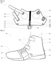
- the upper part 151 of the rigid element 150 can be fixed to the rear part 111 of the main part 110 via height-adjustable fixing means.
- said height-adjustable fixing means may comprise a first element 153 located on the upper part 151 of the rigid element 150 and a second element 154 located on the rear part 111 of the main part 110. The first 153 and second 154 elements will cooperate with each other to hold the first element 153 on the second element 154 in several positions.
- the first element 153 may correspond to an oblong hole which allows the user to adjust the rigid element 150 to the desired height depending on the thickness of the sole of their shoe.
- the second element 154 for its part, can correspond to threaded inserts.
- perforations 155 are made in the high-density reinforcement part 160 and in the main part 110 at the rear part 111.
- said threaded inserts are placed within the perforations 155, as illustrated in [ Fig.5 ].
- said threaded inserts are held at the rear part 111 of the main part 110 using the high density reinforcement part 160.
- the threaded inserts corresponding to the second element 154 and the oblong hole, corresponding to the first element 153, are respectively dimensioned to receive and allow screws 156 to pass through.
- the upper part 151 of the rigid element 150 can be fixed to the rear part 111 of the main part 110 simply by screwing or by clipping.
- said device 100 may further comprise a foam 170 positioned on the interior wall 113 of said main part 110.
- said foam 170 fits the shape of the person's ankle 200.
- said foam 170 is positioned in the upper part of said device, namely at the level of the person's Achilles tendon.
- said foam 170 can be placed on said plate 160.
- said foam 170 can be placed directly on the interior wall 113 of said main part 110 and the two reinforcements 120. As such, the foam 170 can replace the high density reinforcement piece 160. It is only necessary that such foam 170 combines both high density and sufficient rigidity.
- Said foam 170 can be fixed to said device 100 by sewing, by gluing or otherwise.
- foam 170 makes it possible in particular to absorb shocks and reduce the effects of friction which could cause burns on the person's ankle 200.
- the foam 170 may consist of a synthetic rubber type EPDM, abbreviation of ethylene, propylene, diene and monomer, preferably with a thickness of 5 millimeters and a density of around 140 kilograms per meter cube.
- the invention is not limited to the choice of material for the foam 170 or even to its thickness and its density, those skilled in the art can use any other material compatible with the use made of it within the invention, namely a material absorbing shock and providing sufficient comfort and adhesion.
- said ankle protection device of a person 100 may further comprise a 180 sock wrapping the front of the foot. Said sock is fixed to said device 100 via press studs 116 and 181.
- the main part 110 has on its outer wall 114 on either side in the lower part of said device, at the level of the neck -foot of the person, press studs 116, as illustrated on [ Fig.6 ].
- said sock 180 comprises on each side a press button 181 intended to cooperate with each press button of the main part 116.
- such a sock 180 can mainly consist of a first piece 182 of flexible fabric, jersey type, covered on the top with a second part 183 in anti-abrasion material, oily leather type or other previously described.
- the sock 180 can be perforated at the level of the part in contact with the toe clip of the motorized vehicle in order to promote support.
- an additional part sewn on the interior wall 113 of said main part 110 and in direct contact with the ankle 200 of the person: this part corresponding to an interior lining of said device 100.
- a piece can be made of cotton jersey, a material with the advantage of being a very good insulator and providing a thermoregulatory effect limiting perspiration phenomena.
- a piece of felt-type fabric, a light material with natural breathability could be sewn to the rear part 111 of the main part 110 in order to cover the base of the threaded inserts, avoiding in particular wear of the interior lining.
Landscapes
- Health & Medical Sciences (AREA)
- Public Health (AREA)
- General Health & Medical Sciences (AREA)
- Engineering & Computer Science (AREA)
- Biomedical Technology (AREA)
- Heart & Thoracic Surgery (AREA)
- Vascular Medicine (AREA)
- Life Sciences & Earth Sciences (AREA)
- Animal Behavior & Ethology (AREA)
- Orthopedic Medicine & Surgery (AREA)
- Nursing (AREA)
- Veterinary Medicine (AREA)
- Epidemiology (AREA)
- Footwear And Its Accessory, Manufacturing Method And Apparatuses (AREA)
- Professional, Industrial, Or Sporting Protective Garments (AREA)
Claims (10)
- Vorrichtung zum Schutz des Knöchels einer Person (100), dadurch gekennzeichnet, dass sie umfasst:- einen Hauptteil (110), welcher aus einem abriebfesten Material besteht, welcher den Knöchel (200) umhüllt und über einen hinteren Teil (111), der auf der Rückseite des Knöchels (200) auf Höhe der Achillessehne der Person angeordnet ist, einen vorderen Teil (112), der auf der Vorderseite des Knöchels (200) auf Höhe des Rists der Person angeordnet ist, eine Innenwand (113), die dazu bestimmt ist, mit dem Knöchel (200) in Kontakt zu sein, und eine Außenwand (114) verfügt,- zwei Verstärkungen (120), die an der Innenwand (113) des Hauptteils (110) in Höhe der Malleolus des Knöchels (200) der Person befestigt sind,- Schließmittel, die an der Außenwand (114) des Hauptteils (110) befestigt sind und es ermöglichen, die genannte Vorrichtung (100) gegen den Dübel (200) zu halten und festzuklemmen,- ein starres Element (150) welcher zwei Teile, die durch eine Krümmung miteinander verbunden sind, einen oberen Teil (151), der an dem hinteren Teil (111) des Hauptteils (110) befestigt ist, und einen unteren Teil (152), der dazu bestimmt ist, unter der Ferse eines Schuhs der Person positioniert zu werden, aufweist.
- Vorrichtung (100) zum Schutz des Knöchels einer Person nach dem vorhergehenden Anspruch, bei der das Material, aus dem das Hauptteil (110) besteht, ein Fettleder ist.
- Vorrichtung zum Schutz des Knöchels einer Person (100) nach einem der vorhergehenden Ansprüche, bei der die Verschlussmittel Riemen (130) und Schnallen (140) entsprechen, die auf beiden Seiten der Außenwand (114) des Hauptteils (110) befestigt sind.
- Vorrichtung zum Schutz des Knöchels einer Person (100) nach dem vorhergehenden Anspruch, bei der die Riemen (130) hauptsächlich aus Leder bestehen und einen Bereich aus Klettmaterial aufweisen.
- Vorrichtung zum Schutz des Knöchels einer Person (100) nach einem der vorhergehenden Ansprüche, bei der die Verstärkungen (120) aus thermoplastischem Polyurethan, Acrylnitril-Butadien-Styrol oder Polypropylen bestehen.
- Vorrichtung zum Schutz des Knöchels einer Person (100) nach einem der vorhergehenden Ansprüche, die außerdem eine hochdichte Verstärkungsplatte (160) umfasst, die an der Innenwand (113) des Hauptteils (110) befestigt ist und es ermöglicht, die beiden Verstärkungen (120) an der Innenwand (113) des Hauptteils (110) in Position zu halten.
- Vorrichtung zum Schutz des Knöchels einer Person (100) nach einem der vorhergehenden Ansprüche, bei der das starre Element (150) am hinteren Teil (111) des Hauptteils (110) über höhenverstellbare Befestigungsmittel befestigt ist, die ein erstes Element (153), das sich auf dem oberen Teil (151) des starren Elements (150) befindet, und ein zweites Element (154), das sich auf dem hinteren Teil (111) des Hauptteils (110) befindet, umfassen, so dass das erste (153) und das zweite (154) Element miteinander zusammenwirken werden, um das erste Element (153) auf dem zweiten Element (154) in mehreren Positionen zu halten.
- Vorrichtung zum Schutz des Knöchels einer Person (100) nach den Ansprüchen 6 und 7, bei der das erste Element (153) ein Langloch ist und das zweite Element (154) aus Gewindeeinsätzen besteht, die am hinteren Teil (111) des Hauptteils (110) durch das hochdichte Verstärkungsteil (160) gehalten werden, um Schrauben (156) aufzunehmen, wobei das Langloch es ermöglicht, die Schrauben (156) durchzulassen und eine Anpassung an die gewünschte Höhe zu gewährleisten.
- Vorrichtung zum Schutz des Knöchels einer Person (100) nach einem der vorhergehenden Ansprüche, die außerdem einen Schaumstoff (170) umfasst, der an der Innenwand (113) des Hauptteils (110) positioniert ist und sich an die Form des Knöchels (200) der Person anpasst.
- Vorrichtung zum Schutz des Knöchels einer Person (100) nach einem der vorhergehenden Ansprüche, die außerdem eine Socke (180) umfasst, die den Vorderfuß umhüllt, wobei die Socke (180) und der Hauptteil (110) jeweils mit Druckknöpfen (181, 116) versehen sind, um die Socke (180) an der Vorrichtung (100) zu befestigen, wobei die Druckknöpfe (181) der Socke (180) dazu bestimmt sind, mit den Druckknöpfen (116) des Hauptteils (110) zusammenzuwirken.
Applications Claiming Priority (1)
| Application Number | Priority Date | Filing Date | Title |
|---|---|---|---|
| FR2106053A FR3123560B1 (fr) | 2021-06-08 | 2021-06-08 | Dispositif de protection de cheville |
Publications (3)
| Publication Number | Publication Date |
|---|---|
| EP4101331A1 EP4101331A1 (de) | 2022-12-14 |
| EP4101331C0 EP4101331C0 (de) | 2024-03-27 |
| EP4101331B1 true EP4101331B1 (de) | 2024-03-27 |
Family
ID=76920962
Family Applications (1)
| Application Number | Title | Priority Date | Filing Date |
|---|---|---|---|
| EP22020263.4A Active EP4101331B1 (de) | 2021-06-08 | 2022-06-04 | Knöchelschutz |
Country Status (2)
| Country | Link |
|---|---|
| EP (1) | EP4101331B1 (de) |
| FR (1) | FR3123560B1 (de) |
Family Cites Families (2)
| Publication number | Priority date | Publication date | Assignee | Title |
|---|---|---|---|---|
| WO2000018348A1 (en) * | 1998-10-01 | 2000-04-06 | Ascheman James M | Ankle brace |
| WO2014176368A1 (en) * | 2013-04-23 | 2014-10-30 | Mueller Sports Medicine, Inc. | Ankle brace |
-
2021
- 2021-06-08 FR FR2106053A patent/FR3123560B1/fr not_active Expired - Fee Related
-
2022
- 2022-06-04 EP EP22020263.4A patent/EP4101331B1/de active Active
Also Published As
| Publication number | Publication date |
|---|---|
| EP4101331C0 (de) | 2024-03-27 |
| FR3123560A1 (fr) | 2022-12-09 |
| EP4101331A1 (de) | 2022-12-14 |
| FR3123560B1 (fr) | 2023-06-30 |
Similar Documents
| Publication | Publication Date | Title |
|---|---|---|
| EP0710451B1 (de) | Sportschuh | |
| EP1468621B1 (de) | Schuh | |
| EP1174048B1 (de) | Spannvorrichtung für Schuhwerk | |
| EP2060196B1 (de) | Schuh mit verbesserter Festziehmöglichkeit des Schafts | |
| EP0086909B1 (de) | Einlage für Sportschuhe mit steifer oder halbsteifer Schale | |
| EP1040768A1 (de) | Sportschuh mit weicher Versteifungsstruktur | |
| EP0941675B1 (de) | Skischuh | |
| FR2472352A3 (fr) | Chaussure de sport a poche de rangement | |
| FR2826554A1 (fr) | Chaussure | |
| EP0521287B1 (de) | Lauf- oder Wanderschuh für Bergtouren mit innerer Spannhalterung | |
| FR2534459A1 (fr) | Chaussure de ski de fond | |
| EP4101331B1 (de) | Knöchelschutz | |
| FR3097104A1 (fr) | Ensemble formé d’une culotte d’équitation et d’un coussinet protecteur | |
| EP1319346B1 (de) | Sportschuh mit variabeler Steifigkeit | |
| FR2748371A1 (fr) | Protection dorsale pour motocycliste | |
| EP0972462B1 (de) | Sportschuh | |
| FR2873303A1 (fr) | Patin a roulettes | |
| FR2914156A1 (fr) | Chaussure de sport. | |
| EP0941676B1 (de) | Schuh für Gleitsporten | |
| CH714417A1 (fr) | Chaussure de sport sans appui sur la malléole. | |
| FR3044525B1 (fr) | Languette pour chausson interieur de chaussure de sport | |
| FR3050619A1 (fr) | Tensionneur pour serrage de chaussure | |
| FR2816174A1 (fr) | Protection d'une articulation | |
| WO2003073881A1 (fr) | Chaussures de course pour patinage | |
| FR2879586A1 (fr) | Caparacon permettant d'assurer la protection des chevaux lors des corridas |
Legal Events
| Date | Code | Title | Description |
|---|---|---|---|
| STAA | Information on the status of an ep patent application or granted ep patent |
Free format text: STATUS: UNKNOWN |
|
| PUAI | Public reference made under article 153(3) epc to a published international application that has entered the european phase |
Free format text: ORIGINAL CODE: 0009012 |
|
| STAA | Information on the status of an ep patent application or granted ep patent |
Free format text: STATUS: THE APPLICATION HAS BEEN PUBLISHED |
|
| AK | Designated contracting states |
Kind code of ref document: A1 Designated state(s): AL AT BE BG CH CY CZ DE DK EE ES FI FR GB GR HR HU IE IS IT LI LT LU LV MC MK MT NL NO PL PT RO RS SE SI SK SM TR |
|
| STAA | Information on the status of an ep patent application or granted ep patent |
Free format text: STATUS: REQUEST FOR EXAMINATION WAS MADE |
|
| GRAP | Despatch of communication of intention to grant a patent |
Free format text: ORIGINAL CODE: EPIDOSNIGR1 |
|
| STAA | Information on the status of an ep patent application or granted ep patent |
Free format text: STATUS: GRANT OF PATENT IS INTENDED |
|
| 17P | Request for examination filed |
Effective date: 20230610 |
|
| RBV | Designated contracting states (corrected) |
Designated state(s): AL AT BE BG CH CY CZ DE DK EE ES FI FR GB GR HR HU IE IS IT LI LT LU LV MC MK MT NL NO PL PT RO RS SE SI SK SM TR |
|
| RIC1 | Information provided on ipc code assigned before grant |
Ipc: A61F 5/01 20060101ALI20230627BHEP Ipc: A43B 7/20 20060101AFI20230627BHEP |
|
| INTG | Intention to grant announced |
Effective date: 20230710 |
|
| GRAJ | Information related to disapproval of communication of intention to grant by the applicant or resumption of examination proceedings by the epo deleted |
Free format text: ORIGINAL CODE: EPIDOSDIGR1 |
|
| STAA | Information on the status of an ep patent application or granted ep patent |
Free format text: STATUS: REQUEST FOR EXAMINATION WAS MADE |
|
| GRAS | Grant fee paid |
Free format text: ORIGINAL CODE: EPIDOSNIGR3 |
|
| STAA | Information on the status of an ep patent application or granted ep patent |
Free format text: STATUS: GRANT OF PATENT IS INTENDED |
|
| GRAP | Despatch of communication of intention to grant a patent |
Free format text: ORIGINAL CODE: EPIDOSNIGR1 |
|
| INTC | Intention to grant announced (deleted) | ||
| INTG | Intention to grant announced |
Effective date: 20231024 |
|
| GRAA | (expected) grant |
Free format text: ORIGINAL CODE: 0009210 |
|
| STAA | Information on the status of an ep patent application or granted ep patent |
Free format text: STATUS: THE PATENT HAS BEEN GRANTED |
|
| AK | Designated contracting states |
Kind code of ref document: B1 Designated state(s): AL AT BE BG CH CY CZ DE DK EE ES FI FR GB GR HR HU IE IS IT LI LT LU LV MC MK MT NL NO PL PT RO RS SE SI SK SM TR |
|
| REG | Reference to a national code |
Ref country code: GB Ref legal event code: FG4D Free format text: NOT ENGLISH |
|
| REG | Reference to a national code |
Ref country code: CH Ref legal event code: EP |
|
| REG | Reference to a national code |
Ref country code: DE Ref legal event code: R096 Ref document number: 602022002473 Country of ref document: DE |
|
| REG | Reference to a national code |
Ref country code: IE Ref legal event code: FG4D Free format text: LANGUAGE OF EP DOCUMENT: FRENCH |
|
| U01 | Request for unitary effect filed |
Effective date: 20240416 |
|
| U07 | Unitary effect registered |
Designated state(s): AT BE BG DE DK EE FI FR IT LT LU LV MT NL PT SE SI Effective date: 20240425 |
|
| U20 | Renewal fee for the european patent with unitary effect paid |
Year of fee payment: 3 Effective date: 20240522 |
|
| PG25 | Lapsed in a contracting state [announced via postgrant information from national office to epo] |
Ref country code: GR Free format text: LAPSE BECAUSE OF FAILURE TO SUBMIT A TRANSLATION OF THE DESCRIPTION OR TO PAY THE FEE WITHIN THE PRESCRIBED TIME-LIMIT Effective date: 20240628 |
|
| PG25 | Lapsed in a contracting state [announced via postgrant information from national office to epo] |
Ref country code: HR Free format text: LAPSE BECAUSE OF FAILURE TO SUBMIT A TRANSLATION OF THE DESCRIPTION OR TO PAY THE FEE WITHIN THE PRESCRIBED TIME-LIMIT Effective date: 20240327 Ref country code: RS Free format text: LAPSE BECAUSE OF FAILURE TO SUBMIT A TRANSLATION OF THE DESCRIPTION OR TO PAY THE FEE WITHIN THE PRESCRIBED TIME-LIMIT Effective date: 20240627 |
|
| PG25 | Lapsed in a contracting state [announced via postgrant information from national office to epo] |
Ref country code: RS Free format text: LAPSE BECAUSE OF FAILURE TO SUBMIT A TRANSLATION OF THE DESCRIPTION OR TO PAY THE FEE WITHIN THE PRESCRIBED TIME-LIMIT Effective date: 20240627 Ref country code: NO Free format text: LAPSE BECAUSE OF FAILURE TO SUBMIT A TRANSLATION OF THE DESCRIPTION OR TO PAY THE FEE WITHIN THE PRESCRIBED TIME-LIMIT Effective date: 20240627 Ref country code: HR Free format text: LAPSE BECAUSE OF FAILURE TO SUBMIT A TRANSLATION OF THE DESCRIPTION OR TO PAY THE FEE WITHIN THE PRESCRIBED TIME-LIMIT Effective date: 20240327 Ref country code: GR Free format text: LAPSE BECAUSE OF FAILURE TO SUBMIT A TRANSLATION OF THE DESCRIPTION OR TO PAY THE FEE WITHIN THE PRESCRIBED TIME-LIMIT Effective date: 20240628 |
|
| PG25 | Lapsed in a contracting state [announced via postgrant information from national office to epo] |
Ref country code: IS Free format text: LAPSE BECAUSE OF FAILURE TO SUBMIT A TRANSLATION OF THE DESCRIPTION OR TO PAY THE FEE WITHIN THE PRESCRIBED TIME-LIMIT Effective date: 20240727 |
|
| PG25 | Lapsed in a contracting state [announced via postgrant information from national office to epo] |
Ref country code: SM Free format text: LAPSE BECAUSE OF FAILURE TO SUBMIT A TRANSLATION OF THE DESCRIPTION OR TO PAY THE FEE WITHIN THE PRESCRIBED TIME-LIMIT Effective date: 20240327 |
|
| PG25 | Lapsed in a contracting state [announced via postgrant information from national office to epo] |
Ref country code: ES Free format text: LAPSE BECAUSE OF FAILURE TO SUBMIT A TRANSLATION OF THE DESCRIPTION OR TO PAY THE FEE WITHIN THE PRESCRIBED TIME-LIMIT Effective date: 20240327 |
|
| PG25 | Lapsed in a contracting state [announced via postgrant information from national office to epo] |
Ref country code: CZ Free format text: LAPSE BECAUSE OF FAILURE TO SUBMIT A TRANSLATION OF THE DESCRIPTION OR TO PAY THE FEE WITHIN THE PRESCRIBED TIME-LIMIT Effective date: 20240327 |
|
| PG25 | Lapsed in a contracting state [announced via postgrant information from national office to epo] |
Ref country code: PL Free format text: LAPSE BECAUSE OF FAILURE TO SUBMIT A TRANSLATION OF THE DESCRIPTION OR TO PAY THE FEE WITHIN THE PRESCRIBED TIME-LIMIT Effective date: 20240327 |
|
| PG25 | Lapsed in a contracting state [announced via postgrant information from national office to epo] |
Ref country code: SK Free format text: LAPSE BECAUSE OF FAILURE TO SUBMIT A TRANSLATION OF THE DESCRIPTION OR TO PAY THE FEE WITHIN THE PRESCRIBED TIME-LIMIT Effective date: 20240327 |
|
| PG25 | Lapsed in a contracting state [announced via postgrant information from national office to epo] |
Ref country code: SM Free format text: LAPSE BECAUSE OF FAILURE TO SUBMIT A TRANSLATION OF THE DESCRIPTION OR TO PAY THE FEE WITHIN THE PRESCRIBED TIME-LIMIT Effective date: 20240327 Ref country code: SK Free format text: LAPSE BECAUSE OF FAILURE TO SUBMIT A TRANSLATION OF THE DESCRIPTION OR TO PAY THE FEE WITHIN THE PRESCRIBED TIME-LIMIT Effective date: 20240327 Ref country code: RO Free format text: LAPSE BECAUSE OF FAILURE TO SUBMIT A TRANSLATION OF THE DESCRIPTION OR TO PAY THE FEE WITHIN THE PRESCRIBED TIME-LIMIT Effective date: 20240327 Ref country code: PL Free format text: LAPSE BECAUSE OF FAILURE TO SUBMIT A TRANSLATION OF THE DESCRIPTION OR TO PAY THE FEE WITHIN THE PRESCRIBED TIME-LIMIT Effective date: 20240327 Ref country code: IS Free format text: LAPSE BECAUSE OF FAILURE TO SUBMIT A TRANSLATION OF THE DESCRIPTION OR TO PAY THE FEE WITHIN THE PRESCRIBED TIME-LIMIT Effective date: 20240727 Ref country code: ES Free format text: LAPSE BECAUSE OF FAILURE TO SUBMIT A TRANSLATION OF THE DESCRIPTION OR TO PAY THE FEE WITHIN THE PRESCRIBED TIME-LIMIT Effective date: 20240327 Ref country code: CZ Free format text: LAPSE BECAUSE OF FAILURE TO SUBMIT A TRANSLATION OF THE DESCRIPTION OR TO PAY THE FEE WITHIN THE PRESCRIBED TIME-LIMIT Effective date: 20240327 |
|
| REG | Reference to a national code |
Ref country code: DE Ref legal event code: R097 Ref document number: 602022002473 Country of ref document: DE |
|
| PG25 | Lapsed in a contracting state [announced via postgrant information from national office to epo] |
Ref country code: MC Free format text: LAPSE BECAUSE OF FAILURE TO SUBMIT A TRANSLATION OF THE DESCRIPTION OR TO PAY THE FEE WITHIN THE PRESCRIBED TIME-LIMIT Effective date: 20240327 |
|
| PLBE | No opposition filed within time limit |
Free format text: ORIGINAL CODE: 0009261 |
|
| STAA | Information on the status of an ep patent application or granted ep patent |
Free format text: STATUS: NO OPPOSITION FILED WITHIN TIME LIMIT |
|
| 26N | No opposition filed |
Effective date: 20250103 |
|
| PG25 | Lapsed in a contracting state [announced via postgrant information from national office to epo] |
Ref country code: IE Free format text: LAPSE BECAUSE OF NON-PAYMENT OF DUE FEES Effective date: 20240604 |
|
| U20 | Renewal fee for the european patent with unitary effect paid |
Year of fee payment: 4 Effective date: 20250520 |
|
| PG25 | Lapsed in a contracting state [announced via postgrant information from national office to epo] |
Ref country code: CY Free format text: LAPSE BECAUSE OF FAILURE TO SUBMIT A TRANSLATION OF THE DESCRIPTION OR TO PAY THE FEE WITHIN THE PRESCRIBED TIME-LIMIT; INVALID AB INITIO Effective date: 20220604 |
|
| REG | Reference to a national code |
Ref country code: CH Ref legal event code: H13 Free format text: ST27 STATUS EVENT CODE: U-0-0-H10-H13 (AS PROVIDED BY THE NATIONAL OFFICE) Effective date: 20260127 |
|
| PG25 | Lapsed in a contracting state [announced via postgrant information from national office to epo] |
Ref country code: HU Free format text: LAPSE BECAUSE OF FAILURE TO SUBMIT A TRANSLATION OF THE DESCRIPTION OR TO PAY THE FEE WITHIN THE PRESCRIBED TIME-LIMIT; INVALID AB INITIO Effective date: 20220604 |
|
| PG25 | Lapsed in a contracting state [announced via postgrant information from national office to epo] |
Ref country code: CH Free format text: LAPSE BECAUSE OF NON-PAYMENT OF DUE FEES Effective date: 20250630 |