EP4101273B1 - A weeding mechanism and a weeding vehicle including the weeding mechanism - Google Patents
A weeding mechanism and a weeding vehicle including the weeding mechanism Download PDFInfo
- Publication number
- EP4101273B1 EP4101273B1 EP21178793.2A EP21178793A EP4101273B1 EP 4101273 B1 EP4101273 B1 EP 4101273B1 EP 21178793 A EP21178793 A EP 21178793A EP 4101273 B1 EP4101273 B1 EP 4101273B1
- Authority
- EP
- European Patent Office
- Prior art keywords
- weeding
- arm
- sledge
- shaft
- tool
- Prior art date
- Legal status (The legal status is an assumption and is not a legal conclusion. Google has not performed a legal analysis and makes no representation as to the accuracy of the status listed.)
- Active
Links
Images


Classifications
-
- A—HUMAN NECESSITIES
- A01—AGRICULTURE; FORESTRY; ANIMAL HUSBANDRY; HUNTING; TRAPPING; FISHING
- A01B—SOIL WORKING IN AGRICULTURE OR FORESTRY; PARTS, DETAILS, OR ACCESSORIES OF AGRICULTURAL MACHINES OR IMPLEMENTS, IN GENERAL
- A01B39/00—Machines specially adapted for working soil on which crops are growing
- A01B39/12—Machines specially adapted for working soil on which crops are growing for special purposes, e.g. for special culture
- A01B39/18—Machines specially adapted for working soil on which crops are growing for special purposes, e.g. for special culture for weeding
-
- A—HUMAN NECESSITIES
- A01—AGRICULTURE; FORESTRY; ANIMAL HUSBANDRY; HUNTING; TRAPPING; FISHING
- A01M—CATCHING, TRAPPING OR SCARING OF ANIMALS; APPARATUS FOR THE DESTRUCTION OF NOXIOUS ANIMALS OR NOXIOUS PLANTS
- A01M21/00—Apparatus for the destruction of unwanted vegetation, e.g. weeds
- A01M21/02—Apparatus for mechanical destruction
-
- C—CHEMISTRY; METALLURGY
- C07—ORGANIC CHEMISTRY
- C07K—PEPTIDES
- C07K16/00—Immunoglobulins [IG], e.g. monoclonal or polyclonal antibodies
- C07K16/18—Immunoglobulins [IG], e.g. monoclonal or polyclonal antibodies against material from animals or humans
- C07K16/22—Immunoglobulins [IG], e.g. monoclonal or polyclonal antibodies against material from animals or humans against growth factors ; against growth regulators
-
- C—CHEMISTRY; METALLURGY
- C07—ORGANIC CHEMISTRY
- C07K—PEPTIDES
- C07K16/00—Immunoglobulins [IG], e.g. monoclonal or polyclonal antibodies
- C07K16/18—Immunoglobulins [IG], e.g. monoclonal or polyclonal antibodies against material from animals or humans
- C07K16/28—Immunoglobulins [IG], e.g. monoclonal or polyclonal antibodies against material from animals or humans against receptors, cell surface antigens or cell surface determinants
- C07K16/30—Immunoglobulins [IG], e.g. monoclonal or polyclonal antibodies against material from animals or humans against receptors, cell surface antigens or cell surface determinants from tumour cells
-
- G—PHYSICS
- G01—MEASURING; TESTING
- G01N—INVESTIGATING OR ANALYSING MATERIALS BY DETERMINING THEIR CHEMICAL OR PHYSICAL PROPERTIES
- G01N33/00—Investigating or analysing materials by specific methods not covered by groups G01N1/00 - G01N31/00
- G01N33/48—Biological material, e.g. blood, urine; Haemocytometers
- G01N33/50—Chemical analysis of biological material, e.g. blood, urine; Testing involving biospecific ligand binding methods; Immunological testing
- G01N33/53—Immunoassay; Biospecific binding assay; Materials therefor
- G01N33/575—Immunoassay; Biospecific binding assay; Materials therefor for cancer
- G01N33/5758—Immunoassay; Biospecific binding assay; Materials therefor for cancer involving compounds serving as markers for tumours, cancers or neoplasias, e.g. cellular determinants, receptors, heat shock/stress proteins, A-protein, oligosaccharides or metabolites
- G01N33/57595—Immunoassay; Biospecific binding assay; Materials therefor for cancer involving compounds serving as markers for tumours, cancers or neoplasias, e.g. cellular determinants, receptors, heat shock/stress proteins, A-protein, oligosaccharides or metabolites involving intracellular compounds
-
- C—CHEMISTRY; METALLURGY
- C07—ORGANIC CHEMISTRY
- C07K—PEPTIDES
- C07K2317/00—Immunoglobulins specific features
- C07K2317/20—Immunoglobulins specific features characterized by taxonomic origin
-
- C—CHEMISTRY; METALLURGY
- C07—ORGANIC CHEMISTRY
- C07K—PEPTIDES
- C07K2317/00—Immunoglobulins specific features
- C07K2317/30—Immunoglobulins specific features characterized by aspects of specificity or valency
- C07K2317/34—Identification of a linear epitope shorter than 20 amino acid residues or of a conformational epitope defined by amino acid residues
-
- C—CHEMISTRY; METALLURGY
- C07—ORGANIC CHEMISTRY
- C07K—PEPTIDES
- C07K2317/00—Immunoglobulins specific features
- C07K2317/90—Immunoglobulins specific features characterized by (pharmaco)kinetic aspects or by stability of the immunoglobulin
- C07K2317/92—Affinity (KD), association rate (Ka), dissociation rate (Kd) or EC50 value
-
- G—PHYSICS
- G01—MEASURING; TESTING
- G01N—INVESTIGATING OR ANALYSING MATERIALS BY DETERMINING THEIR CHEMICAL OR PHYSICAL PROPERTIES
- G01N2333/00—Assays involving biological materials from specific organisms or of a specific nature
- G01N2333/435—Assays involving biological materials from specific organisms or of a specific nature from animals; from humans
- G01N2333/475—Assays involving growth factors
- G01N2333/485—Epidermal growth factor [EGF] (urogastrone)
Definitions
- the present invention relates to a weeding mechanism for an autonomous weeding vehicle.
- the present invention also relates to a weeding vehicle for performing automatic weeding using the weeding mechanism.
- the invention relates to the technical field of agricultural machinery applications.
- Autonomous weeding vehicles also named robot weeders, are used to automatically remove weeds during the seedling stage of crops.
- Such weeding vehicles may comprise a movable platform, a drive mechanism for driving the platform, sensors for detecting the weed plants, and a weeding mechanism connected to the platform and comprising a weeding tool adapted to carry out a weeding action on the detected weed plants.
- the removal of the weed plants can be made in different ways. It is common to use chemical weeding. However, a disadvantage of chemical weeding is that the herbicide is wasteful and easily pollutes the environment. Mechanical weeding, such as cutting, is better for the environment. There exist different types of cutting tools for weeding vehicles.
- CN101707992 discloses a weeding robot comprising an inter-row cutting mechanism arranged under the trolley, and an in-row weeding mechanism.
- the inter-row cutting mechanism comprises a first weeding mechanism that removes the weed below the trolley during traveling of the trolley.
- the in-row weeding mechanism comprises a weed cutting roller protruding from the trolley.
- the outer surface of the weed cutting roller has a blade edge rotating at high speed and the weed are cut due to the high-speed rotation of the roller.
- the inter-row cutting mechanism comprises two spaced apart rotating cylindrical saw discs. The rotating saw discs are moved between two crops in the row while removing the weed between the crops in the row.
- a problem with the rotating saw discs is that they will stir the soil when they are moved along the row of crops. This causes stirring of weed seed into the soil, and consequently stimulates growing of the weed. Another problem is that the stirring discs may harm the crop plants if the weed plant is growing close to a crop plant.
- CN109511356 discloses a weeding vehicle comprising a robotic arm movable in multiple degrees of freedom and holding a cutting tool in the form of a rotating disc.
- a disadvantage with this solution is that a robot arm movable in many degrees of freedom is expensive and it is complicated to control the motion of robot arm, which requires extensive robot programming.
- EP3811748 discloses a weeding mechanism including an actuator adapted to upon activation linearly move a cutting tool in a forth and back motion relative to the platform.
- the weeding mechanism comprises at least one horizontal shaft arranged movable relative the platform, and a vertical distance element attached to one end of the horizontal shaft.
- the cutting tool is attached to a lower end of the vertical distance element.
- the actuator is arranged to move the horizontal shaft along its axis so that the cutting tool is moved in a linear motion relative to the platform.
- Document RU 2 703 092 C1 discloses a weeding mechanism for an autonomous weeding vehicle with all features according to the preamble of the subject-matter of claim 1.
- the weeding mechanism comprises
- This weeding mechanism makes it possible to move the weeding tool in 2 degrees of freedom. Thus, it is possible to execute different types of cutting sequences in two dimensions.
- the weeding tool can be controlled in a vertical direction as well as a horizontal direction. Thus, it is possible to reach the weed plant without touching the soil and by that avoid stirring the soil.
- the first actuator is arranged to move the first sledge up and down along the first shaft
- the second actuator is arranged to move the second sledge up and down along the second shaft.
- the position of the weeding tool depends on the positions of the first and second sledges.
- the motions of the weeding tool are controlled by controlling the linear motions of the two sledges along the shafts.
- the motions of the first and second sledges are controlled by the two actuators.
- Each of the first and second sledges can be moved independently up and down along the first and second shafts.
- the combination of the motions of the sledges and the pivotal arrangement of the first and second arms allows the weeding tool to perform an arbitrary motion within a 2-dimensinal working area.
- the weeding mechanism according to the invention is simple, and costs significantly less than a robotic arm movable in multiple degrees of freedom. Further, the weeding mechanism can rapidly move the weeding tool with high precision.
- the weeding tool can be any type of weeding tool, such as a cutting tool, a laser, or a burner.
- the weeding mechanism is particularly suitable for moving a cutting tool in a cutting motion.
- the weeding tool can be directly or indirectly connected to at least one of the first and second arms.
- each of the first and second actuators comprises a linear motor and a drive belt.
- the combination of a linear motor and a drive belt achieves a high-speed weeding mechanism and makes it possible to carry fast motions with the weeding tool.
- the weeding tool can carry out about 6 - 7 cutting sequences per second.
- the motor is a brushless DC motor.
- the drive belt is a timing belt.
- a timing belt is a tooth belt with teeth on an inside surface.
- the first and second shafts define a plane
- the first and second arms are arranged so that the weeding tool performs a motion in parallel with the plane when the first sledge and the second sledge are moved along the first and second shafts.
- the weeding tool can be moved vertically as well as horizontally in a plane defined by the first and second shafts.
- the first and second arms are arranged so that the weeding tool can be moved to a left side of the first and second shafts as well as to a right side of the first and second shafts in the plane.
- the weeding tool can carry out weeding actions on both sides of the weeding mechanism.
- the weeding tool has a cutting edge extending perpendicular to the plane defined by the first and second shafts.
- the weeding tool is a cutting tool. The cutting edge is moved in a direction in parallel with the plane upon moving the first and second sledges.
- the first and second arms are arranged so that the cutting edge can perform a linear motion in a first direction parallel with the plane when the first sledge and the second sledge are moved relative each other along the first and second shafts.
- the first direction is a horizontal direction. This is advantageous since is allows the cutting tool to perform a linear motion during cutting of the weed plant.
- the first and second arms are arranged so that the cutting edge can perform a linear motion in a second direction in parallel with the plane when the first sledge and the second sledge are synchronously moved along the first and second shafts.
- the second direction is a vertical direction. This makes it possible to lower and raise the cutting tool before and after the cutting, and by that avoid stirring of weed seed into the soil.
- the first arm is pivotably connected to the first sledge so that the first arm can perform a pivotal movement with respect to the first shaft about a first rotational axis
- the second arm is pivotably connected to the second sledge so that the second arm can perform a pivotal movement with respect to the second shaft about a second rotational axis
- the second arm is pivotably connected to the first arm so that the second arm can perform a pivotal movement with respect to the first arm about a third rotational axis
- the first, second and third rotational axes are parallel and perpendicular to a plane defined by the first and second shafts.
- the weeding tool is attached to a lower end of the first arm.
- the second arm is connected to the first arm at a distance from the lower end of the first arm.
- the distance is at least 30 mm, preferably at least 50 mm, and most preferably at least 100 mm.
- the width of the lower end of the weeding mechanism, which is connected to the weeding tool is reduced compared to having the second arm attached to the lower end of the first arm.
- the reduced width of the lower end of the weeding mechanism makes it possible for the weeding tool to enter between two seed plants close to each other without causing damage to the seed plants.
- the width of the first arm in a direction perpendicular to the plane defined by the first and second shafts is less than 30 mm, preferably less than 25 mm and most preferably less than 20 mm.
- a thinner arm makes it easier for it to enter between two seed plants close to each other without causing damage to the seed plants.
- the width of the weeding tool in a direction perpendicular to the plane defined by the first and second shafts is less than 30 mm, preferably less than 25 mm and most preferably less than 20 mm.
- a thinner tool makes it easier for it to enter between two seed plants close to each other without causing damage to the seed plants.
- an upper end of the second arm is pivotably connected to the second sledge and a lower end of the second arm is pivotably connected to the first arm at a distance from the lower end of the first arm.
- an upper end of the first arm is pivotably connected to the first sledge and the weeding tool is connected to the lower end of the first arm.
- each of the first and second actuators comprises a motor with a variable speed having a rotary shaft arranged to rotate in two opposite directions.
- the weeding mechanism further comprises:
- This embodiment of the invention is more robust and can stand the high speed of the weeding tool.
- Another aim of the present invention is to provide an improved autonomous weeding vehicle.
- the weeding vehicle comprises a weeding mechanism according to the invention, and a weeding control unit for controlling the first and second actuators so that the weeding tool carries out a weeding action.
- the weeding vehicle comprises one or more sensors adapted to detect weed plants, and the weeding control unit controls the first and second actuators so that the weeding tool carries out weeding actions based upon output from sensors.
- the weeding mechanism is adapted to carry out a weeding action upon receiving an activation command
- the weeding control unit is configured to send activation commands to the weeding mechanism
- the weeding vehicle comprises two or more weeding mechanisms which can operate independently of each other.
- the weeding vehicle comprises two or more weeding mechanisms which can operate independently of each other.
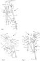
- FIG. 1 shows an example of a weeding mechanism 1 according to the invention.
- the weeding mechanism comprises a weeding tool 2, and a mechanism for moving the weeding tool comprising a first shaft 3, and a second shaft 5 arranged spaced apart from the first shaft 3.
- the first and second shafts 3, 5 are arranged in parallel.
- the first and second shafts 3, 5 are vertically arranged when the weeding mechanism is mounted on a weeding vehicle.
- the shafts can be arranged with a small angle between them.
- the first and second shaft define a plane, which preferably is vertical when the weeding mechanism is mounted on the weeding vehicle.
- the shafts 3, 5 are made of metal, for example, stainless steel.
- the weeding mechanism 1 further comprises a first sledge 7 linearly movable along the first shaft 3, and a second sledge 9 linearly movable along the second shaft 5.
- the sledges can be moved up as well as down along the shafts 3, 5.
- Each of the first and second sledges 7, 9 is provided with a through hole for receiving one of the shafts 3, 5.
- the through holes are provided with bearings, such as slide bearings, to reduce the friction between the shafts and the sledges during the motions of the sledges along the shafts.
- the sledges 7, 9 are, for example, made of a plastic material or metal, such as aluminium.
- the weeding mechanism 1 comprises a first actuator 11 arranged to move the first sledge 7 along the first shaft 3, and a second actuator 13 arranged to move the second sledge 9 along the second shaft 5.
- the first and second actuators 11, 13 are arranged so that the first and second sledges 7, 9 can be moved independently of each other up and down along the shafts.
- each of the first and second actuators 11, 13 comprises a motor 11a, 13a, and a drive belt 11b, 13b.
- each of the first and second actuators 11, 13 comprises a linear motor.
- a linear motor is an electric motor arranged to produce a linear motion instead of a rotating motion.
- each of the first and second actuators 11, 13 comprises a brushless linear motor, for example, a brushless DC motor, which can perform high performance positioning of the sledges 7, 9 with respect to the shafts 3, 5.
- the drive belts 11b, 13b are timing belts.
- a timing belt is usually a toothed belt with teeth on an inside surface.
- the actuators 11, 13 may include timing chains, cambelts, or gear racks.
- the weeding mechanism 1 further comprises a first arm 15 pivotably connected to the first sledge 7 so that the first arm can perform a pivotal movement with respect to the first shaft 3 about a first rotational axis A, and a second arm 17 pivotably connected to the second sledge 9 so that the second arm 17 can perform a pivotal movement with respect to the second shaft 5 about a second rotational axis B.
- the first and second rotational axes A, B are parallel, and perpendicular to the plane defined by the first and second shafts 3, 5.
- the first rotational axis A extends through a joint 16 between the first arm 15 and the first shaft 3.
- the second rotational axis B extends through a joint 18 between the second arm 17 and the second shaft 5.
- an upper end of the first arm 15 is pivotably connected to the first sledge 7 and an upper end of the second arm 17 is pivotably connected to the second sledge 9.
- a lower end of the second arm 17 is pivotably connected to the first arm 15 so that the second arm 17 can perform a pivotal movement with respect to the first arm 15 about a third rotational axis C.
- the third rotational axis C is parallel to the first and second rotational axes A, B, and consequentially perpendicular to the plane defined by the first and second shafts 3, 5.
- the third rotational axis C extends through a third joint 20 between the first and second arms 15, 17.
- the weeding tool will perform a motion in parallel with the plane defined by the first and second shafts when the first and second sledges 7, 9 are moved along the first and second shafts.
- the weeding tool 2 is attached to a lower end 22 of the first arm 15, and the second arm 17 is pivotally connected to the first arm 15 at a distance d from the lower end of the first arm 15.
- the distance d is at least 30 mm, preferably the distance d is at least 50 mm, and most preferably at least 100 mm.
- the distance d is 150 mm.
- a lower part of the first arm 15, defined between the lower end 22 of the first arm and the connection to the second arm 17, functions as a tool holder 24.
- the tool holder 24 is as thin as possible so that the tool holder can be moved between two weed plants that are close to each other without causing any harm on the weed plants.
- the width w1 of the tool holder in a direction perpendicular to the plane defined by the first and second shafts 3, 5 is less than 30 mm, preferably less than 25 mm, and most preferably less than 20 mm.
- the width w2 of the weeding tool in a direction perpendicular to the plane defined by the first and second shafts 3, 5 should be as small as possible.
- the width of the weeding tool in the direction perpendicular to the plane defined by the first and second shafts 3, 5 is less than 30 mm, preferably less than 25 mm, and most preferably less than 20 mm.
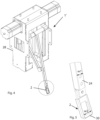
- the weeding mechanism is also provided with attaching members 26 for attaching the weeding mechanism 1 to a housing 28, shown in figure 4 .
- the attaching members 26 are threaded upper parts of the shafts 3, 5.
- the weeding mechanism 1 is based on a 2d-delta design.
- the two motors 11a, 13a are driving the two belts 11b, 13b that move the two sledges 7, 9 up and down the two shafts 3, 5, respectively.
- the sledges 7, 9 are then connected to the joints 16, 18 of the two arms 15, 17. This creates a weeding mechanism with 2 degrees of freedom capable of executing arbitrary cutting sequences in 2 dimensions.
- Figures 2 and 3 show another example of a weeding mechanism 1' according to the invention.
- Figure 2 shows the weeding mechanism 1' in a left perspective view.
- Figure 3 shows the weeding mechanism in a right perspective view.
- the weeding mechanism 1' comprises a third shaft 3' arranged in parallel and spaced apart from the first shaft 3, and a fourth shaft 5' arranged in parallel and spaced apart from the second shaft 5.
- the weeding mechanism 1' further comprises a third sledge 7' arranged linearly movable along the third shaft 3' and a fourth sledge 9' arranged linearly movable along the fourth shaft 5'.
- the third sledge 7' is connected to the first sledge 7 so that the first and third sledges 7, 7' are moved interdependently.
- the weeding mechanism 1' comprises a first rotary shaft 8 rotatably connected between the first and third sledges 7, 7'.
- the first sledge 7 comprises a space for receiving one end of the first rotary shaft 8
- the third sledge 7' comprises a corresponding space for receiving the other end of the first rotary shaft 8.
- the first rotary shaft 8 is arranged rotatable with respect to the first and third sledges 7, 7' about the first rotational axis A.
- the weeding mechanism 1' comprises a second rotary shaft 8' rotatably connected between the second and fourth sledges 9, 9'.
- the second sledge 9 comprises a space for receiving one end of the second rotary shaft 8'
- the fourth sledge 9' comprises a corresponding space for receiving the other end of the second rotary shaft 8'.
- the second rotary shaft 8 is arranged rotatable with respect to the second and fourth sledges 9, 9' about the second rotational axis B.
- the first arm 15 is attached to the first rotary shaft 8 and the second arm 17 is attached to the second rotary shaft 8'.
- the first arm 15 is pivoted about the first rotational axis A by moving the first and third sledges 7, 7' along the first and third shafts 3, 3' and with respect to the second and fourth sledges 9, 9'.
- the second arm 17 is pivoted about the second rotational axis B by moving the second and fourth sledges 9, 9' along the second and fourth shafts 5, 5' and with respect to the first and third sledges 7, 7'.
- the first actuator 11 is arranged to simultaneously move the first and third sledges 7, 7' along the first and third shafts 3, 3', and the second actuator 13 is arranged to simultaneously move the second and fourth sledges 9, 9' along the second and fourth shafts 5, 5'.
- This embodiment of the invention is more robust and can stand high speed of the weeding tool.
- Figure 4 shows the weeding mechanism 1' arranged in a housing 28.
- the weeding tool 2 can be designed in many ways.
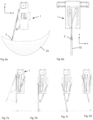
- Figure 5 shows an example of a weeding tool 2.
- the weeding tool 2 is a cutting tool having a cutting edge 30 extending perpendicular to the plane defined by the first and second shafts 3, 5.
- the arms 15, 17 will move the cutting edge 30 in a direction in parallel with the plane defined by the first and second shafts upon moving the first and second sledges.
- the weeding tool comprises a U-shaped part.
- a lower portion of the U-shaped part comprises the cutting edge 30.
- the U-shaped part is fixedly or removably attached to the lower end 22 of the first arm 15.
- the weeding tool 2 is made of metal, such as stainless steel.
- the weeding tool 2 is designed to cut the roots of the weed plats and/or pull the weed plant out of the ground.
- Figures 6a-b illustrate the working area 32 of the weeding mechanism.
- Figure 6a illustrates the working area in a z-y plane, which is the plane defined by the first and second shafts.
- the weeding tool can reach both sides of the housing of weeding mechanism.
- the first and second arms 15, 17 are arranged so that the weeding tool 2 can be moved to a left side of the first and second shafts as well as to a right side of the first and second shafts in the plane.
- the weeding tool can carry out weeding actions on both sides of the weeding mechanism.
- Figure 6b illustrates the working area 32 in a z-x plane, i.e. a plane perpendicular to the plane defined by the first and second shafts.
- the working area in the z-x plane corresponds to the width w2 of the weeding tool.
- the first and second arms 15, 17 are arranged so that the weeding tool can perform a linear motion in an y-direction when the first sledge and the second sledge are moved relative each other along the first and second shafts. This is advantageous since is allows the cutting tool to perform a linear motion during cutting of the weed plant.
- the first and second arms 15, 17 are arranged so that the weeding tool can perform a linear motion in a z- direction when the first sledge and the second sledge are synchronously moved along the first and second shafts. This makes it possible to lower and raise the cutting tool before and after the cutting, and by that avoid stirring of weed seed in the soil.
- Figures 7a-d illustrate an example of how to use of the cutting mechanism for removing a weed plant.
- the weeding tool 2 is moved from its current position to a position close to the weed plant, above the soil, and at one side of the weed plant, as shown in figure 7a .
- the weeding mechanism is now ready to execute a strike.
- the weeding tool 2 is lowered in a vertical direction at one side of the weed plant until the tool 2 reaches the soil.
- the tool can be lowered about 2 cm into the soil, as shown in figure 7b .
- the tool 2 is linearly moved in a horizontal direction so that the cutting edge of the tool 2 cuts the roots of the weed plant and/or pulls the weed plant out of the ground, as shown in figure 7c .
- the tool 2 is returned to an idle position by linearly moving the tool 2 in the vertical direction, as shown in figure 7d .
- Figure 8 shows in a perspective view an example of a weeding vehicle 40 including a weeding mechanism.
- Figure 9 shows the weeding vehicle in a front view
- figure 10 shows the weeding vehicle in a side view.
- the weeding vehicle 40 comprises the weeding mechanism 1'.
- the weeding vehicle 40 can also comprise the weeding mechanism 1, or other embodiments of the weeding mechanism according to the invention.
- the weeding vehicle 40 comprises three weeding mechanisms 1' arranged spaced apart in an y-direction with respect to the vehicle 40 at a bottom side of the vehicle 40.
- the number of weeding mechanisms 1' can vary, between one or more than three.
- the vehicle 40 is moving in a x-direction and the tool 2 can be moved in the y-direction and in the z-direction with respect to the vehicle 40.
- the weeding tool 2 is a cutting tool having a cutting edge 30 arranged substantially perpendicular to the y direction to be able to cut the weed plants during the movement of the cutting tool 2 in the y direction.
- the weeding vehicle 40 further comprises a control unit 12 for controlling the weeding mechanism 1, 1'.
- the control unit 42 is adapted to control the first and second actuators 11, 13 so that the weeding tool 2 carries out a weeding action, for example, as illustrated in figures 7a-d .
- the control unit 42 can also be adapted to determine when the weeding action is to be carried out and to generate an activation command when the weeding action shall start.
- the control unit 42 can be the same control unit used to perform vehicle functions, such as controlling the motions of the platform of the weeding vehicle.
- the control unit 42 comprises a data processing circuitry for controlling the weeding mechanism 1, 1' and memory for storing control programs for controlling the weeding mechanism to carry weeding actions.
- the memory can also be used for storing operating parameters for controlling the weeding mechanism.
- the memory may comprise two or more control programs including instructions for carrying out different types of weeding actions with the weeding tool.
- the data processing circuitry can be any suitable means for processing data, such as a computer, a CPU, and programmable circuits, such as FPGAs.
- the memory may, for example, comprise EPROM, EEPROM, flash memory, RAM, a solid-state disc drive, a hard disc drive, or any other memory type or combinations of memory types.
- the weeding action can be carried out by programming instructions stored in the memory and executed by the data processing circuitry.
- the control unit 42 controls the motions of sledges along the shafts by providing control signals to the motors 11a, 13a of the first and second actuators 11, 13, and by that controls the motions of the weeding tool 2.
- the weeding vehicle 40 comprises sensors 44 adapted to detect weed plants, and the control unit 42 controls the first and second actuators so that the weeding tool carries out weeding actions based on output from the sensors.
- the number of sensors 44 may vary. In this example, each weeding mechanism 1' is provided with two sensors 44, as shown in figure 10 .
- the weeding vehicle 40 comprises a movable platform 46, and a drive mechanism for driving the platform 46.
- the platform 46 is provided with a plurality of wheels.
- the drive mechanism for driving the platform comprises a plurality of motors.
- the motors are, for example, electrical hub motors mounted on the wheels.
- the weeding mechanism 1, 1' is connected to the platform 46 for carrying out weeding of weed plants.
- the weeding control unit 42 is configured to send activation commands to the weeding mechanism.
- the weeding mechanism 1, 1' is adapted to carry out a weeding action upon receiving an activation command from the weeding control unit 42.
- the weeding tool 2 has a fixed position relative to the platform 46 in the x-direction.
- the current position of the tool in the x-direction is known if the current position of the platform is known.
- the purpose of the weeding action is to remove or kill the weed plant.
- Different types of weeding tools 20 can be used.
- the weeding tool 2 can be a cutting tool, a laser, a spraying nozzle, or a gas nozzle.
- the weeding action to be carried out upon receiving the activation command depends on the type of the weeding tool. For example, if the weeding tool is a cutting tool, the cutting tool is moved to the weed plant to be removed upon receiving the activation command.
- the weeding vehicle 40 comprises a plant detection system adapted to detect weed plants at a distance ahead of the weeding tool 2 while the platform 46 is moving in the x- direction.
- the x-direction is the direction of travel of the platform.
- the plant detection system comprises one or more sensors 44 arranged in connection to the platform for identifying the plants.
- the sensor 44 is a camera taking images in the form of photos of the ground in front of the weeding tool 2.
- the sensor 44 can be an energy reflection analysis sensor such as a laser sensor.
- the plant detection system comprises a vision system arranged to obtain the images from the sensors 44.
- the vision system is adapted to detect the plants and to determine the positions of the detected plants based on the received images.
- the weeding control unit 42 comprises a data processing circuitry configured to obtain information on the speed of the platform from the drive mechanism, to obtain the positions of the detected weed plants, the current position of the tool, and the speed of the platform, and to send an activation command to the weeding mechanism when the tool has reached an optimal tool activation position.
- the plant detection system and the control unit 42 may share the same data processing circuitry.
- the present invention is not limited to the embodiments disclosed but may be varied and modified within the scope of the following claims.
- the length of the arms may vary.
- the sledges can be designed in different ways.
- the tool can be directly connected to the first arm and/or the first arm, or indirectly connected to the first arm and/or the first arm, for example via, an extension part.
Landscapes
- Life Sciences & Earth Sciences (AREA)
- Health & Medical Sciences (AREA)
- Chemical & Material Sciences (AREA)
- Engineering & Computer Science (AREA)
- Immunology (AREA)
- Molecular Biology (AREA)
- Organic Chemistry (AREA)
- Environmental Sciences (AREA)
- Mechanical Engineering (AREA)
- Biochemistry (AREA)
- Medicinal Chemistry (AREA)
- General Health & Medical Sciences (AREA)
- Soil Sciences (AREA)
- Biophysics (AREA)
- Biomedical Technology (AREA)
- Cell Biology (AREA)
- Hematology (AREA)
- Proteomics, Peptides & Aminoacids (AREA)
- Genetics & Genomics (AREA)
- Urology & Nephrology (AREA)
- Pathology (AREA)
- General Physics & Mathematics (AREA)
- Food Science & Technology (AREA)
- Analytical Chemistry (AREA)
- Biotechnology (AREA)
- Microbiology (AREA)
- Physics & Mathematics (AREA)
- Insects & Arthropods (AREA)
- Pest Control & Pesticides (AREA)
- Wood Science & Technology (AREA)
- Zoology (AREA)
- Soil Working Implements (AREA)
Priority Applications (4)
| Application Number | Priority Date | Filing Date | Title |
|---|---|---|---|
| ES21178793T ES2978781T3 (es) | 2021-06-10 | 2021-06-10 | Un mecanismo de escardado y un vehículo de escardado que incluye el mecanismo de escardado |
| PL21178793.2T PL4101273T3 (pl) | 2021-06-10 | 2021-06-10 | Mechanizm pielący i pojazd pielący zawierający mechanizm pielący |
| EP21178793.2A EP4101273B1 (en) | 2021-06-10 | 2021-06-10 | A weeding mechanism and a weeding vehicle including the weeding mechanism |
| US17/836,478 US12422436B2 (en) | 2021-06-10 | 2022-06-09 | Weeding mechanism and a weeding vehicle including the weeding mechanism |
Applications Claiming Priority (1)
| Application Number | Priority Date | Filing Date | Title |
|---|---|---|---|
| EP21178793.2A EP4101273B1 (en) | 2021-06-10 | 2021-06-10 | A weeding mechanism and a weeding vehicle including the weeding mechanism |
Publications (3)
| Publication Number | Publication Date |
|---|---|
| EP4101273A1 EP4101273A1 (en) | 2022-12-14 |
| EP4101273C0 EP4101273C0 (en) | 2024-02-28 |
| EP4101273B1 true EP4101273B1 (en) | 2024-02-28 |
Family
ID=76392159
Family Applications (1)
| Application Number | Title | Priority Date | Filing Date |
|---|---|---|---|
| EP21178793.2A Active EP4101273B1 (en) | 2021-06-10 | 2021-06-10 | A weeding mechanism and a weeding vehicle including the weeding mechanism |
Country Status (4)
| Country | Link |
|---|---|
| US (1) | US12422436B2 (pl) |
| EP (1) | EP4101273B1 (pl) |
| ES (1) | ES2978781T3 (pl) |
| PL (1) | PL4101273T3 (pl) |
Families Citing this family (5)
| Publication number | Priority date | Publication date | Assignee | Title |
|---|---|---|---|---|
| US12201044B2 (en) | 2018-02-05 | 2025-01-21 | FarmWise Labs, Inc. | Method for autonomously weeding crops in an agricultural field |
| US12543614B2 (en) * | 2022-07-03 | 2026-02-10 | Emmet Edward Hand | Robotic weed removal system for aesthetic mulch gardens |
| US20240260562A1 (en) * | 2023-02-07 | 2024-08-08 | FarmWise Labs, Inc. | Automated agriculture implement |
| US12120973B2 (en) | 2023-02-07 | 2024-10-22 | FarmWise Labs, Inc. | Crop detection system and/or method |
| CN118362253B (zh) * | 2024-06-19 | 2024-09-27 | 海南创航科技有限公司 | 一种激光除草机组件防水性能检测设备 |
Family Cites Families (11)
| Publication number | Priority date | Publication date | Assignee | Title |
|---|---|---|---|---|
| DE4323315C2 (de) * | 1993-07-12 | 1996-08-29 | Wiedenmann Gmbh | Bearbeitungsgerät für die Tiefenlockerung von Böden |
| EP1967055A1 (de) * | 2007-03-06 | 2008-09-10 | Redexim Handel-en Exploitatie Maatschappij B.V. | Bodenbearbeitungsvorrichtung |
| CN101707992B (zh) | 2009-10-15 | 2011-01-05 | 南京林业大学 | 高效除草机器人 |
| DE102014104876B4 (de) * | 2014-04-04 | 2018-04-26 | Wiedenmann Gmbh | Bodenbearbeitungsgerät |
| DE102015209879A1 (de) * | 2015-05-29 | 2016-12-01 | Robert Bosch Gmbh | Unkrautregulierungsvorrichtung |
| CN106889052A (zh) * | 2015-12-18 | 2017-06-27 | 巴东县丰太农业专业合作社 | 一种除草机 |
| CA3029134A1 (en) * | 2015-12-18 | 2017-06-22 | Realmfive, Inc. | Autonomous integrated farming system |
| CN109511356B (zh) | 2019-01-08 | 2023-10-24 | 安徽农业大学 | 一种基于深度视觉的智能除草机器人系统及控制方法 |
| RU2703092C1 (ru) * | 2019-01-25 | 2019-10-15 | федеральное государственное бюджетное образовательное учреждение высшего образования "Волгоградский государственный аграрный университет" (ФГБОУ ВО Волгоградский ГАУ) | Робот-пропольщик |
| US11483958B2 (en) * | 2019-07-23 | 2022-11-01 | Vision Robotics Corporation | Intelligent crop maintenance device with independently controlled blades |
| DK3811748T3 (da) | 2019-10-24 | 2022-07-25 | Ekobot Ab | Lugemaskine og fremgangsmåde til udførelse af lugning under anvendelse af lugemaskinen |
-
2021
- 2021-06-10 PL PL21178793.2T patent/PL4101273T3/pl unknown
- 2021-06-10 EP EP21178793.2A patent/EP4101273B1/en active Active
- 2021-06-10 ES ES21178793T patent/ES2978781T3/es active Active
-
2022
- 2022-06-09 US US17/836,478 patent/US12422436B2/en active Active
Also Published As
| Publication number | Publication date |
|---|---|
| EP4101273A1 (en) | 2022-12-14 |
| EP4101273C0 (en) | 2024-02-28 |
| ES2978781T3 (es) | 2024-09-19 |
| US20220394912A1 (en) | 2022-12-15 |
| PL4101273T3 (pl) | 2024-04-29 |
| US12422436B2 (en) | 2025-09-23 |
Similar Documents
| Publication | Publication Date | Title |
|---|---|---|
| EP4101273B1 (en) | A weeding mechanism and a weeding vehicle including the weeding mechanism | |
| EP3811748B1 (en) | A weeding machine and a method for carrying out weeding using the weeding machine | |
| US9119388B2 (en) | Selectively eradicating plants | |
| CN107690280B (zh) | 除草装置 | |
| EP3815510A1 (en) | Plant removal apparatus and method | |
| CN114009417A (zh) | 一种适用于旱田农作物的除草装置 | |
| WO2022013978A1 (ja) | エンドエフェクタ | |
| JP4247895B2 (ja) | 除草方法及び装置 | |
| EP4329465B1 (fr) | Dispositif d'actionnement intermittent pour outil agricole | |
| JP2020174546A (ja) | 収穫方法及び果菜収穫装置 | |
| EP4417050B1 (en) | A weeding device and a method for removing weeds | |
| RU2785580C1 (ru) | Мобильное роботизированное шасси для надреза мульчирующей пленки над растением с последующей ее фиксацией | |
| CN217241484U (zh) | 一种可自适应地形的收割机 | |
| NL2028781B1 (en) | Agricultural manipulator; assembly thereof with a robot arm | |
| JP2021182905A (ja) | 切断装置 | |
| US20240000060A1 (en) | Weeding robot mechanism | |
| CN118716040B (zh) | 一种罩笼式棉花打顶末端执行器 | |
| US3315753A (en) | Crop thinner | |
| US20260083062A1 (en) | Lawn mower with grass directing system | |
| JP2025154312A (ja) | 除草装置 | |
| EP3123846A1 (en) | Active blade of row weeder | |
| Emanuel | Design of a new end effector for a robotic arm for grapes harvesting | |
| Fadlallah et al. | A review of weed detection and control robots: A world without weeds | |
| JP2000060516A (ja) | 玉葱の加工器 | |
| JP2007228869A (ja) | 除草機 |
Legal Events
| Date | Code | Title | Description |
|---|---|---|---|
| PUAI | Public reference made under article 153(3) epc to a published international application that has entered the european phase |
Free format text: ORIGINAL CODE: 0009012 |
|
| STAA | Information on the status of an ep patent application or granted ep patent |
Free format text: STATUS: THE APPLICATION HAS BEEN PUBLISHED |
|
| AK | Designated contracting states |
Kind code of ref document: A1 Designated state(s): AL AT BE BG CH CY CZ DE DK EE ES FI FR GB GR HR HU IE IS IT LI LT LU LV MC MK MT NL NO PL PT RO RS SE SI SK SM TR |
|
| STAA | Information on the status of an ep patent application or granted ep patent |
Free format text: STATUS: REQUEST FOR EXAMINATION WAS MADE |
|
| 17P | Request for examination filed |
Effective date: 20230529 |
|
| RBV | Designated contracting states (corrected) |
Designated state(s): AL AT BE BG CH CY CZ DE DK EE ES FI FR GB GR HR HU IE IS IT LI LT LU LV MC MK MT NL NO PL PT RO RS SE SI SK SM TR |
|
| GRAP | Despatch of communication of intention to grant a patent |
Free format text: ORIGINAL CODE: EPIDOSNIGR1 |
|
| STAA | Information on the status of an ep patent application or granted ep patent |
Free format text: STATUS: GRANT OF PATENT IS INTENDED |
|
| INTG | Intention to grant announced |
Effective date: 20231026 |
|
| GRAS | Grant fee paid |
Free format text: ORIGINAL CODE: EPIDOSNIGR3 |
|
| GRAA | (expected) grant |
Free format text: ORIGINAL CODE: 0009210 |
|
| STAA | Information on the status of an ep patent application or granted ep patent |
Free format text: STATUS: THE PATENT HAS BEEN GRANTED |
|
| AK | Designated contracting states |
Kind code of ref document: B1 Designated state(s): AL AT BE BG CH CY CZ DE DK EE ES FI FR GB GR HR HU IE IS IT LI LT LU LV MC MK MT NL NO PL PT RO RS SE SI SK SM TR |
|
| REG | Reference to a national code |
Ref country code: GB Ref legal event code: FG4D |
|
| REG | Reference to a national code |
Ref country code: CH Ref legal event code: EP |
|
| REG | Reference to a national code |
Ref country code: DE Ref legal event code: R096 Ref document number: 602021009749 Country of ref document: DE |
|
| REG | Reference to a national code |
Ref country code: IE Ref legal event code: FG4D |
|
| U01 | Request for unitary effect filed |
Effective date: 20240321 |
|
| U07 | Unitary effect registered |
Designated state(s): AT BE BG DE DK EE FI FR IT LT LU LV MT NL PT SE SI Effective date: 20240327 |
|
| PG25 | Lapsed in a contracting state [announced via postgrant information from national office to epo] |
Ref country code: IS Free format text: LAPSE BECAUSE OF FAILURE TO SUBMIT A TRANSLATION OF THE DESCRIPTION OR TO PAY THE FEE WITHIN THE PRESCRIBED TIME-LIMIT Effective date: 20240628 |
|
| PG25 | Lapsed in a contracting state [announced via postgrant information from national office to epo] |
Ref country code: GR Free format text: LAPSE BECAUSE OF FAILURE TO SUBMIT A TRANSLATION OF THE DESCRIPTION OR TO PAY THE FEE WITHIN THE PRESCRIBED TIME-LIMIT Effective date: 20240529 |
|
| PG25 | Lapsed in a contracting state [announced via postgrant information from national office to epo] |
Ref country code: RS Free format text: LAPSE BECAUSE OF FAILURE TO SUBMIT A TRANSLATION OF THE DESCRIPTION OR TO PAY THE FEE WITHIN THE PRESCRIBED TIME-LIMIT Effective date: 20240528 Ref country code: HR Free format text: LAPSE BECAUSE OF FAILURE TO SUBMIT A TRANSLATION OF THE DESCRIPTION OR TO PAY THE FEE WITHIN THE PRESCRIBED TIME-LIMIT Effective date: 20240228 |
|
| U20 | Renewal fee for the european patent with unitary effect paid |
Year of fee payment: 4 Effective date: 20240617 |
|
| PG25 | Lapsed in a contracting state [announced via postgrant information from national office to epo] |
Ref country code: RS Free format text: LAPSE BECAUSE OF FAILURE TO SUBMIT A TRANSLATION OF THE DESCRIPTION OR TO PAY THE FEE WITHIN THE PRESCRIBED TIME-LIMIT Effective date: 20240528 Ref country code: NO Free format text: LAPSE BECAUSE OF FAILURE TO SUBMIT A TRANSLATION OF THE DESCRIPTION OR TO PAY THE FEE WITHIN THE PRESCRIBED TIME-LIMIT Effective date: 20240528 Ref country code: IS Free format text: LAPSE BECAUSE OF FAILURE TO SUBMIT A TRANSLATION OF THE DESCRIPTION OR TO PAY THE FEE WITHIN THE PRESCRIBED TIME-LIMIT Effective date: 20240628 Ref country code: HR Free format text: LAPSE BECAUSE OF FAILURE TO SUBMIT A TRANSLATION OF THE DESCRIPTION OR TO PAY THE FEE WITHIN THE PRESCRIBED TIME-LIMIT Effective date: 20240228 Ref country code: GR Free format text: LAPSE BECAUSE OF FAILURE TO SUBMIT A TRANSLATION OF THE DESCRIPTION OR TO PAY THE FEE WITHIN THE PRESCRIBED TIME-LIMIT Effective date: 20240529 |
|
| PG25 | Lapsed in a contracting state [announced via postgrant information from national office to epo] |
Ref country code: SM Free format text: LAPSE BECAUSE OF FAILURE TO SUBMIT A TRANSLATION OF THE DESCRIPTION OR TO PAY THE FEE WITHIN THE PRESCRIBED TIME-LIMIT Effective date: 20240228 |
|
| PG25 | Lapsed in a contracting state [announced via postgrant information from national office to epo] |
Ref country code: CZ Free format text: LAPSE BECAUSE OF FAILURE TO SUBMIT A TRANSLATION OF THE DESCRIPTION OR TO PAY THE FEE WITHIN THE PRESCRIBED TIME-LIMIT Effective date: 20240228 |
|
| PG25 | Lapsed in a contracting state [announced via postgrant information from national office to epo] |
Ref country code: SK Free format text: LAPSE BECAUSE OF FAILURE TO SUBMIT A TRANSLATION OF THE DESCRIPTION OR TO PAY THE FEE WITHIN THE PRESCRIBED TIME-LIMIT Effective date: 20240228 |
|
| PG25 | Lapsed in a contracting state [announced via postgrant information from national office to epo] |
Ref country code: SM Free format text: LAPSE BECAUSE OF FAILURE TO SUBMIT A TRANSLATION OF THE DESCRIPTION OR TO PAY THE FEE WITHIN THE PRESCRIBED TIME-LIMIT Effective date: 20240228 Ref country code: SK Free format text: LAPSE BECAUSE OF FAILURE TO SUBMIT A TRANSLATION OF THE DESCRIPTION OR TO PAY THE FEE WITHIN THE PRESCRIBED TIME-LIMIT Effective date: 20240228 Ref country code: RO Free format text: LAPSE BECAUSE OF FAILURE TO SUBMIT A TRANSLATION OF THE DESCRIPTION OR TO PAY THE FEE WITHIN THE PRESCRIBED TIME-LIMIT Effective date: 20240228 Ref country code: CZ Free format text: LAPSE BECAUSE OF FAILURE TO SUBMIT A TRANSLATION OF THE DESCRIPTION OR TO PAY THE FEE WITHIN THE PRESCRIBED TIME-LIMIT Effective date: 20240228 |
|
| REG | Reference to a national code |
Ref country code: DE Ref legal event code: R097 Ref document number: 602021009749 Country of ref document: DE |
|
| PLBE | No opposition filed within time limit |
Free format text: ORIGINAL CODE: 0009261 |
|
| STAA | Information on the status of an ep patent application or granted ep patent |
Free format text: STATUS: NO OPPOSITION FILED WITHIN TIME LIMIT |
|
| PG25 | Lapsed in a contracting state [announced via postgrant information from national office to epo] |
Ref country code: MC Free format text: LAPSE BECAUSE OF FAILURE TO SUBMIT A TRANSLATION OF THE DESCRIPTION OR TO PAY THE FEE WITHIN THE PRESCRIBED TIME-LIMIT Effective date: 20240228 |
|
| REG | Reference to a national code |
Ref country code: CH Ref legal event code: PL |
|
| 26N | No opposition filed |
Effective date: 20241129 |
|
| PG25 | Lapsed in a contracting state [announced via postgrant information from national office to epo] |
Ref country code: IE Free format text: LAPSE BECAUSE OF NON-PAYMENT OF DUE FEES Effective date: 20240610 |
|
| PG25 | Lapsed in a contracting state [announced via postgrant information from national office to epo] |
Ref country code: CH Free format text: LAPSE BECAUSE OF NON-PAYMENT OF DUE FEES Effective date: 20240630 |
|
| PGFP | Annual fee paid to national office [announced via postgrant information from national office to epo] |
Ref country code: PL Payment date: 20250513 Year of fee payment: 5 |
|
| U20 | Renewal fee for the european patent with unitary effect paid |
Year of fee payment: 5 Effective date: 20250617 |
|
| PGFP | Annual fee paid to national office [announced via postgrant information from national office to epo] |
Ref country code: ES Payment date: 20250710 Year of fee payment: 5 |
|
| PGFP | Annual fee paid to national office [announced via postgrant information from national office to epo] |
Ref country code: GB Payment date: 20250805 Year of fee payment: 5 |
|
| PG25 | Lapsed in a contracting state [announced via postgrant information from national office to epo] |
Ref country code: CY Free format text: LAPSE BECAUSE OF FAILURE TO SUBMIT A TRANSLATION OF THE DESCRIPTION OR TO PAY THE FEE WITHIN THE PRESCRIBED TIME-LIMIT; INVALID AB INITIO Effective date: 20210610 |
|
| PG25 | Lapsed in a contracting state [announced via postgrant information from national office to epo] |
Ref country code: HU Free format text: LAPSE BECAUSE OF FAILURE TO SUBMIT A TRANSLATION OF THE DESCRIPTION OR TO PAY THE FEE WITHIN THE PRESCRIBED TIME-LIMIT; INVALID AB INITIO Effective date: 20210610 |