EP4100944B1 - Verbesserte mundharmonika - Google Patents
Verbesserte mundharmonika Download PDFInfo
- Publication number
- EP4100944B1 EP4100944B1 EP21702508.9A EP21702508A EP4100944B1 EP 4100944 B1 EP4100944 B1 EP 4100944B1 EP 21702508 A EP21702508 A EP 21702508A EP 4100944 B1 EP4100944 B1 EP 4100944B1
- Authority
- EP
- European Patent Office
- Prior art keywords
- reed
- chamber
- extension dimension
- harmonica
- blown
- Prior art date
- Legal status (The legal status is an assumption and is not a legal conclusion. Google has not performed a legal analysis and makes no representation as to the accuracy of the status listed.)
- Active
Links
Images


Classifications
-
- G—PHYSICS
- G10—MUSICAL INSTRUMENTS; ACOUSTICS
- G10D—STRINGED MUSICAL INSTRUMENTS; WIND MUSICAL INSTRUMENTS; ACCORDIONS OR CONCERTINAS; PERCUSSION MUSICAL INSTRUMENTS; AEOLIAN HARPS; SINGING-FLAME MUSICAL INSTRUMENTS; MUSICAL INSTRUMENTS NOT OTHERWISE PROVIDED FOR
- G10D7/00—General design of wind musical instruments
- G10D7/12—Free-reed wind instruments
- G10D7/14—Mouth-organs
-
- G—PHYSICS
- G10—MUSICAL INSTRUMENTS; ACOUSTICS
- G10D—STRINGED MUSICAL INSTRUMENTS; WIND MUSICAL INSTRUMENTS; ACCORDIONS OR CONCERTINAS; PERCUSSION MUSICAL INSTRUMENTS; AEOLIAN HARPS; SINGING-FLAME MUSICAL INSTRUMENTS; MUSICAL INSTRUMENTS NOT OTHERWISE PROVIDED FOR
- G10D9/00—Details of, or accessories for, wind musical instruments
- G10D9/02—Mouthpieces; Reeds; Ligatures
- G10D9/035—Reeds
Definitions
- the present invention relates to the field of harmonicas, and more generally to free reed wind instruments. It finds a particularly advantageous application in the field of diatonic harmonicas.
- the user would like the opposite, that is to say to vibrate only the aspirated reed 121 while blowing or to vibrate only the blown reed 111 while aspirating.
- This situation is possible when the user is an experienced user, that is to say that he has good mastery of the instrument and when he positions his tongue very particularly while he blows or aspirates.
- This technique is difficult to master, and depends on several factors endogenous factors such as breath control, tongue strengthening, etc., and several exogenous factors, linked for example to the instrument itself.
- the chambers 131 of a 10 harmonica are not airtight spaces, so the air passes through all possible places when the user blows or sucks.
- These different techniques make it possible to obtain notes which are not native to the instrument, and this mainly by playing on the air flow inside and around the chambers.
- the document WO 93/23846 A1 describes a diatonic harmonica.
- the document US 2,595,316 A describes a harmonica whose structure aims to reduce the turbulence created in the chambers to increase the speed of the air flow in the chambers so as to easily obtain natural notes in tune with improved tonal quality and an increased sound volume range.
- the present invention allows for better control of the air flow inside each chamber.
- the soundboard according to the present invention, allows notes not natively present on the instrument to be reached with the reeds sucked in and this in a much simpler way for the user, by directing the air more directly to where it must exit the chamber.
- the soundboard also allows non-native notes to be reached with the blown reeds or the aspirated reeds, this then being able to be a function of the position of the user's tongue.
- box spring helps to direct the air well.
- the fact that it includes material advances allows to further compact the air flow to force it to pass only where it is most effective.
- the additional plate allows notes not natively present on the instrument to be reached with the blown reeds and this in a much simpler way for the user, by directing the air more directly to where it must exit the chamber.
- the additional plate also allows non-native notes to be reached with the reeds drawn or blown, this can then be a function of the position of the user's tongue.
- the additional plate helps to direct the air well.
- the fact that it includes additional material advances and lugs allows to further compact the air flow to force it to pass only where it is most effective.
- the present invention also makes it possible to better manage the sealing of a harmonica, in particular the chambers of a harmonica.
- the present invention also allows for better management of the airflow inside the chambers, to significantly improve the playability of the instrument.
- the present invention provides improved sealing of the chambers of a harmonica, in part by means of a cleverly designed soundboard to solve an endemic problem of diatonic harmonicas: structurally eliminating air leaks between the soundboard and the plates.
- the present invention also makes it possible to improve the responsiveness of the reeds, particularly for playing the notes that are most difficult to trigger.
- the present invention makes it easier to obtain all notes on the instrument, including notes that are generally difficult to access.
- the present invention makes it possible to homogenize the obtaining of all the notes.
- the present invention makes it possible to vibrate the aspirated reeds when the user blows, mainly at the level of the low and medium notes.
- the present invention makes it possible to vibrate the blown reeds when the user aspirates, mainly at the level of the high notes.
- the present invention makes it possible to easily trigger the existing 36 notes over 3 octaves, and even a few additional notes above the highest note.
- the present invention allows a great responsiveness of the harmonica whatever the note to be played.
- the present invention gives the harmonica a very fluid playability allowing to reach and chain the 36 notes to create phrases in all keys.
- the present invention makes it possible to easily play in all 12 keys on a diatonic harmonica, which is supposed to play in only one key.
- the present invention makes it possible to easily play all the pieces with a single diatonic harmonica, where usually a harmonica player uses one harmonica per key of the piece.
- the present invention makes it possible to reduce or even eliminate the twisting effect, mainly through the use of lugs.
- the present invention makes it possible to achieve a laminar pressure in the chamber so as to trigger the opposite reed. Surprisingly, the present invention makes it possible to achieve a laminar regime much faster, and to maintain it more reliably.
- each advancement of material of the soundboard serves to trigger a sucked reed when the user blows so as to trigger a sucked reed, avoiding leaks at the base of the sucked reed and along a portion of the sucked reed, thereby compacting the air and thereby assisting in triggering the sucked reed.
- each advancement of material of the windchest serves to trigger a blown reed when the user sucks so as to trigger a blown reed, avoiding leaks at the base of the sucked reed and along a portion of the sucked reed, thereby compacting the air and thus aiding in the redirection of air toward the blown reed.
- each additional material advancement of the additional plate serves to trigger a blown reed when the user sucks so as to trigger a blown reed, avoiding leaks at the base of the blown reed and along a portion of the blown reed, thereby compacting the air and thereby assisting in triggering the blown reed.
- each additional material advancement of the additional plate serves to trigger a sucked reed when the user blows so as to trigger a sucked reed, avoiding leaks at the base of the blown reed and along a portion of the blown reed, thereby compacting the air and thereby aiding in the redirection of air toward the sucked reed.
- the harmonica according to the present invention may comprise only one of the soundboard and the additional plate.
- the soundboard alone makes it possible to resolve at least in part the problems indicated above, and the same is true of the additional plate.
- the harmonica according to the present invention may thus comprise one of the additional plate and the soundboard, or comprise the soundboard and the additional plate.
- the box spring and the additional plate work in synergy with each other so as to solve at least some of the problems previously indicated even more effectively.
- the box spring and the additional plate are complementary in terms of confining the air flow in the room.
- the present invention also relates to a harmonica chest, preferably diatonic, comprising a first plate comprising a plurality of blown reeds and a second plate comprising a plurality of sucked reeds, said chest comprising a plurality of chambers, each chamber of the plurality of chambers being associated with a complementary pair of reeds comprising a blown reed and a sucked reed, each chamber of the plurality of chambers each comprising an opening configured to allow the user's breath to pass through and intended to each define an oscillatory space for a blown reed and for a sucked reed, said chest being characterized in that each chamber of the plurality of chambers comprises at least one material projection, each material projection being intended to be arranged at least partly opposite a portion of a sucked reed in order to reduce the oscillatory space of said sucked reed and to allow the oscillation of the blown reed of the
- the present invention provides improved sealing of the chambers of a harmonica, in part by means of a cleverly designed soundboard to solve an endemic problem of diatonic harmonicas: structurally eliminating air leaks between the soundboard and the plates.
- Additional plate for harmonica comprising a first plate comprising a plurality of blown reeds and a second plate comprising a plurality of sucked reeds, each blown reed forming a complementary pair of reeds with a sucked reed, said additional plate being intended to be arranged above the first plate, and being characterized in that it comprises at least a plurality of additional material projections, each additional material projection being arranged partly at the less in relation to a portion of a blown reed and being intended to reduce the oscillatory space of said blown reed and, in certain cases to allow the oscillation of the aspirated reed, in other cases the faster redirection of the air towards the end of the blown reed to make it more responsive (put it in oscillatory motion more quickly) and, to allow the oscillation of the aspirated reed of the complementary torque of said blown reed when the user blows into the chamber
- the present invention provides for improved sealing of the chambers of a harmonica, partly through an additional plate cleverly designed to solve an endemic problem of diatonic harmonicas: structurally eliminating air leaks between the soundboard and the plates.
- Kit for harmonica preferably diatonic, comprising at least one soundboard according to the present invention and at least one additional plate according to the present invention.
- each chamber of the plurality of chambers has a bottom opposite the opening and configured to stop the user's breath, two side walls configured to separate a chamber from other adjoining chambers, the upper portion of the chamber being defined in part at least by a portion of at least one blown reed and the lower portion of the chamber being defined in part at least by a portion of at least one aspirated reed complementary to said blown reed.
- At least a portion of the plurality of chambers has a rounded, preferably concave, bottom.
- At least a portion of the plurality of chambers has a width extension dimension greater than the width extension dimension of at least another portion of the plurality of chambers.
- At least a portion of the plurality of chambers has a width extension dimension less than the width extension dimension of at least another portion of the plurality of chambers.
- a narrower width makes it easier to trigger the aspirated reeds by blowing. Due to the distribution of the notes, this is more useful for low notes, hence the fact that these narrow chambers are those corresponding to chambers 1 to 6.
- At least a portion of the plurality of chambers includes sidewalls having a width extension dimension greater than the width extension dimension of the sidewalls of at least another portion of the plurality of chambers.
- At least one sidewall of a portion of the plurality of chambers includes an additional surface, preferably the additional surface including a bevel.
- a bevel shape allows material to be added just after the chamber opening, and extends from the base of the blown reed to the bottom of the chamber.
- At least a portion of the plurality of chambers includes sidewalls having a width extension dimension less than the width extension dimension of the sidewalls of at least another portion of the plurality of chambers.
- At least one sidewall of a portion of the plurality of chambers includes a recess located between the bottom of the chamber and the opening of the chamber.
- each advance of matter extends from the bottom of its chamber toward the opening of its chamber.
- each material advance includes a thickness extension dimension, this thickness extension dimension decreasing from the bottom of its chamber towards the opening of its chamber, preferably defining a ramp.
- At least part of the material advances define a plateau with the bottom of their chamber, this plateau extending according to a plane orthogonal to the extension plane of the side walls of their chamber.
- each of the plurality of chambers includes an air passage for an aspirated reed, and each material projection extends at least partially to at least partially obstruct the air passage for an aspirated reed.
- each material advance has a length extension dimension and the air passage of a drawn reed has a length extension dimension
- the ratio between the length extension dimension of each material advance and the length extension dimension of the air passage of a drawn reed is between 0.1 and 0.9, preferably between 0.2 and 0.5 and advantageously equal to 0.33.
- each of the plurality of chambers includes an air passage for a blown reed, and each additional material projection extends at least partially to at least partially obstruct the air passage of a blown reed.
- each additional material projection has a lengthwise extension dimension and the air passage of a blown reed has a lengthwise extension dimension, the ratio of the lengthwise extension dimension of each material projection to the lengthwise extension dimension of the additional material projection.
- additional and the length extension dimension of the air passage of a blown reed is between 0.1 and 0.9, preferably between 0.3 and 0.7 and advantageously equal to 0.5.
- each additional material advance has a width extension dimension and a length extension dimension
- each blown reed of the plurality of blown reeds includes a width extension dimension and a length extension dimension
- each additional material advance is associated with a blown reed of the plurality of blown reeds
- the ratio between the length extension dimension of an additional material advance and the length extension dimension of its blown reed is between 0.1 and 0.9, preferably between 0.3 and 0.7 and advantageously equal to 0.5.
- each of the plurality of chambers includes a width extension dimension and a length extension dimension
- each additional material advancement has a width extension dimension equal to the width extension dimension of its chamber, and a length extension dimension less than the length extension dimension of its chamber.
- the ratio between the length extension dimension of an additional material advance and the length extension dimension of its chamber is between 0.1 and 0.9, preferably between 0.3 and 0.7 and advantageously equal to 0.5.
- each additional material advance has an inner face facing the inside of its chamber and an outer face facing the outside of its chamber, and each additional material advance includes at least one lug disposed on its inner face.
- each lug extends from the entrance of each chamber toward the bottom of each chamber along a lengthwise extension dimension.
- the lug extends at least partially into the air passage of a blown reed.
- each blown reed of the plurality of blown reeds includes a width extension dimension and a length extension dimension, and each lug is associated with a blown reed of the plurality of blown reeds, and the ratio of the length extension dimension of a lug to the length extension dimension of its blown reed is between 0.01 and 0.9, preferably between 0.1 and 0.7, and advantageously equal to 0.2.
- each material advance has a width extension dimension and a length extension dimension
- each aspirated reed of the plurality of aspirated reeds comprises a width extension dimension and a length extension dimension
- each material advance is associated with a aspirated reed of the plurality of aspirated reeds
- the ratio between the length extension dimension of a material advance and the length extension dimension of its aspirated reed is between 0.1 and 0.9, preferably between 0.2 and 0.5 and advantageously equal to 0.33.
- each of the plurality of chambers includes a width extension dimension and a length extension dimension
- each material advancement has a width extension dimension equal to the width extension dimension of their room, and a length extension dimension less than the length extension dimension of their room.
- the ratio between the length extension dimension of a material advance and the length extension dimension of its chamber is between 0.1 and 0.9, preferably between 0.2 and 0.5 and advantageously equal to 0.33.
- each material advance has an inner face facing the inside of its chamber and an outer face facing the outside of its chamber, and the material advance includes at least one protuberance disposed on its outer face.
- the protuberance has a length extension dimension proportional to the length extension dimension of the material advance comprising said considered protuberance.
- the ratio between the length extension dimension of a protuberance and the length extension dimension of its chamber is between 0.01 and 0.9, preferably between 0.1 and 0.5 and advantageously equal to 0.19.
- the protrusion extends at least partly into the air passage of an aspirated reed.
- each protrusion extends from the bottom of each chamber toward the entrance of each chamber along the length extension dimension.
- the box spring has a flexibility greater than the flexibility of the first plate and the flexibility of the second plate.
- the bed base is more flexible than the first plate and/or the second plate.
- this allows the bed base to improve the sealing between the bed base and the first plate and/or the second plate.
- the present invention preferably uses a more flexible base than the first and second plates instead of having a very flat and very dense base.
- the sealing is improved.
- the invention preferably uses a flexible bed base with crevices so that it compress and the material spreads along the plate(s) and thus seals the micro-air pockets.
- the box spring has a greater flexibility index on its upper part and on its lower part than on its central part according to its thickness dimension.
- the present invention via the preferred use of this so-called flexible bed base, makes it possible to have plates that are not perfectly flat, to have a bed base that is not perfectly flat, to create adhesion at the joint between the plates and the bed base by a slight compression of the bed base. Indeed, it is sufficient to tighten the screws very lightly, and the material forming the bed base deforms, compresses, and extends along the plates, which will further reinforce the seal.
- the screws are tightened to the maximum to prevent as much air as possible from passing between the soundboard and each of the plates. Over time, the plates deform at the screws, which will paradoxically create new air pockets, and the instrument will gradually lose its sealing.
- the present invention cleverly and preferably uses a flexible soundboard, i.e. supple, so the screws can be tightened to a minimum. It is sufficient to position them just enough to ensure that the elements are held together. The flexibility of the edges of the soundboard takes care of sealing the chambers, as described above.
- each material advance includes an end distant from the opening and the bottom of its chamber.
- each material advance is arranged in its chamber so as to allow the passage of an air flow via the suction reed corresponding to its chamber.
- the present invention relates to a modified harmonica soundboard, as well as an additional harmonica plate, and finally a harmonica integrating these two innovative elements.
- Each of these two elements is innovative and each of these innovations is based on the same inventive principle: better control of the air flow in the chamber, and preferably at the periphery of the chamber, of a harmonica, allowing the user to obtain more easily and better control certain musical notes that are difficult to achieve otherwise.
- this innovative soundboard as well as this innovative additional plate can also work together, which further improves the responsiveness of the instrument, the effects of each innovative element being reinforced by those of the other innovative element.
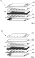
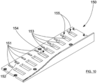
- the first plate 110 is arranged above the bed base 130.
- the second plate 120 is arranged below the bed base 130.
- the additional plate 150 is arranged above the first plate 110.
- the covers 160 are arranged one under the second plate 120, the other above the additional plate 150.
- the first plate 110 therefore comprises the plurality of blown reeds 111.
- This first plate 110 is therefore arranged above the soundboard 130.
- Each blown reed 111 is thus configured to oscillate in a specific oscillatory space 112 when the user blows into the chamber 131 defining said specific oscillatory space 112.
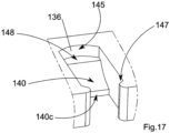
- the blown reeds 111 extend from the opening 135 of the chamber 131 toward the bottom 136 of the chamber 131.
- the end of the blown reed 111 secured to the first plate 110 is at the opening 135 of the chamber 131, preferably above the opening 135 of the chamber 131, and the oscillating end of the blown reed 111 is toward the bottom 136 of the chamber 131.
- the blown reed 111 oscillates, its free end performs back-and-forth movements.
- the length extension dimension of each blown reed 111 is preferably proportional to the length extension dimension 132 of the corresponding chamber 131.
- the second plate 120 comprises a plurality of aspirated reeds 121.
- the second plate 120 is disposed below the windchest 130.
- Each aspirated reed 121 of the plurality of aspirated reeds 121 is configured to oscillate in a clean oscillatory space 122 when the user aspirates from the chamber 131 defining said clean oscillatory space 122.
- the aspirated reeds 121 extend from the bottom 136 of the chamber 131 towards the opening 135 of the chamber 131 in question.
- the end of the suction reed 121 secured to the second plate 120 is located at the bottom 136 of the chamber 131, preferably below the bottom 136 of the chamber 131, and the oscillating end of the suction reed 121 is located towards the opening 135 of the chamber 131.
- the suction reed 121 oscillates, its free end performs back and forth movements.
- the length extension dimension of each suction reed 121 is preferably proportional to the length extension dimension 132 of the corresponding chamber 131.
- the aspirated reeds 121 are mounted head to tail with respect to the blown reeds 111, and that the aspirated reeds 121 and the blown reeds 111 are mounted on either side of the soundboard 130, preferably of the plurality of chambers 131.
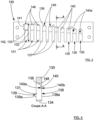
- the bed base 130 comprises a plurality of chambers 131.
- Each chamber 131 comprises an opening 135 configured to allow an incoming or outgoing air flow 170 to pass depending on whether the user blows or sucks.
- Each chamber 131 defines an oscillatory space, respectively 112 and 122, for, respectively, a blown reed 111 and a drawn reed 121.
- the blown reed 111 and the drawn reed 121 of each chamber 131 define a pair of complementary reeds.
- At least one chamber 131 of the plurality of chambers 131 comprises at least one material advance 140.
- each chamber 131 of the plurality of chambers 131 comprises a material advance 140.
- This material advance 140 is configured to reduce the oscillatory space 122 of the aspirated reed 121.
- This material advance 140 is configured to allow the oscillation of a blown reed 111 when the user aspirates air from said chamber 131, preferably by positioning his tongue at a particular angle relative to the direction of the air flow 170.
- This material advance 140 is configured to reduce the oscillatory space 122 of the aspirated reed 121 and to allow the oscillation of a blown reed 111, a reed complementary to said aspirated reed 121, when the user aspirates from the chamber of said aspirated reed 121.
- the present invention is preferably designed so that this phenomenon occurs when the user positions his tongue so as to oscillate the blown reed 111, that is to say when the position of the user's tongue minimizes the space available for air to pass between it and his palate, whether by moving the back of the tongue back toward the throat, or by moving the middle part of the tongue forward toward the teeth.
- the sucked reed 121 will not vibrate as much as the blown reed 111 while the user is nevertheless sucking air through the chamber 131.
- the sucked reed 121 will be blocked in its vibration through a set of pressures established in the chamber 131 considered. It will be noted that, preferably, the aspirated reed 121 does not come into contact with the advance of material 140, and that a pressure effect makes it possible to block the vibration of the latter.
- the present invention advantageously takes advantage of a set of pressures established in the chamber 131 and making it possible to block the vibration of a reed while allowing the vibration of the complementary reed.
- this pressure game is based on the formation of a negative pressure in the chamber 131 at the level of the sucked reed 121 when the user sucks in a configuration intended to vibrate the blown reed 111.
- the suction creates a negative pressure in the chamber 131, therefore causing an overpressure outside the chamber 131 at the lower level 138 and at the upper level 139 of the chamber 131.
- the overpressure at the level of the sucked reed 121 blocks the latter, while the overpressure at the level of the blown reed 111 will cause the latter to vibrate.
- the air circuit 170 in the chamber 131 in this configuration is of less resistance passing via the blown reed 111 than via the sucked reed 121. Therefore, the suction makes it possible to vibrate the blown reed 111.
- FIG 14 This situation is for example illustrated in figure 14 .
- the air flow circulates via the blown reed 111 while the user sucks from the chamber 131, this then allows the blown reed 111 to vibrate while blocking the reed by said pressure set aspirated 121.
- the case of normal aspiration is illustrated in figure 12 , the user sucks air from the chamber 131 and thus vibrates the sucked reed 121, this when he does not arrange his tongue in a particular way.
- the pressure set established in the chamber 131 allows the sucked air to have no choice but to circulate via the blown reed 121, thereby causing the latter to vibrate.
- the user can reach a note not intended by the instrument by sucking from a chamber 131 and thereby causing the blown reed 111 to vibrate, and this much more easily than on a “conventional” harmonica, thanks to the present invention.
- each material advance 140 makes it possible to vibrate a blown reed 121 when the user sucks in a chamber 131, while reducing, or even avoiding, air leaks in the lower part of the chamber; Indeed, the material advance 140 makes it possible to compact the air in the chamber 131 and thus to block the vibration of the sucked reed 121 while allowing the vibration of the blown reed 111.
- each material advance 140 allows a blown reed to vibrate when the user sucks into a chamber 131 via an advantageous material advance geometry.
- the material advance 140 comprises a variable thickness along its length extension dimension 141; This thickness thus defines a ramp; this ramp allows the air 170 to be redirected more quickly to the end of the aspirated reed 121 than in the absence of a ramp. This therefore makes it possible to facilitate the oscillation of the aspirated reed 121 while the user blows into the chamber 131.
- this ramp can have various shapes, such as for example a straight shape, a concave shape or even a convex shape.
- the ramp has a convex shape.
- the material advance 140 forms a right angle with respect to the bottom 136 of the chamber 131.
- the upper surface of the material advance 140 extends in a plane orthogonal to the plane of extension of the side walls 137 of the chamber 131.
- at least a portion of the upper surface of the material advance 140 extends in a plane orthogonal to the extension plane of the side walls 137 of the chamber 131 and then defines a plate 148.
- each material advance 140 makes it possible to reduce the space for the passage of air 170 at the base of the aspirated reed 121 when the user aspirates so as to trigger, that is to say to vibrate, a blown reed 111; This makes it easier to block the aspirated reed 121 and to vibrate the blown reed 111.
- each chamber 131 comprises a bottom 136 opposite the opening 135. This bottom 136 is configured to stop the user's breath and define one of the limits of the chamber 131.
- Each chamber 131 also comprises two side walls 137 configured to separate a chamber 131 from the other contiguous chambers 131.
- the upper part 139 of each chamber 131 is defined by a blown reed 111 and the lower part 138 of each chamber 131 is defined at least in part by a material projection 140 and by at least part of the aspirated reed 121 complementary to said blown reed 111.
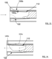
- the bottom of certain chambers 131 has a rounded bottom 136.
- This rounded bottom 136 is concave.
- the figures 3 And 9 illustrate such funds 136.
- the chambers 131 linked to high notes advantageously the chambers linked to holes numbered 7 to 10 of the harmonica 100, have a concave bottom 136 as illustrated in figure 9 .
- This makes it possible to promote the passage of the air 170 through the end of the blown reed 111, and therefore to facilitate the vibration of the blown reed 111 when the user sucks with his tongue in the configuration previously described.
- This makes it possible to chain by sucking the note of the blown reed 111 and that of the sucked reed 121 in a rapid, simple and fluid manner.
- This makes it possible to improve the playability of the notes that are difficult to access and the notes that are easy to access. This makes it possible to reduce any latency between the playability of these two notes.
- a concave shape of the bottom 136 of the chamber 131 makes it possible to give an advantageous direction to the air 170.
- the bottom 136 of the chamber 131 can also be flat or square.
- the figures 5 And 8 and 9 illustrate flat bottoms 136 of chambers 131.
- the bottom 136 may be flat.
- the bottom 136 defines a straight edge with the bed base 130
- the bottom 136 may have a rounding and a top 148.
- the bottom 136 defines a curved edge with the bed base 130.
- the present invention proposes a bottom 136 of chamber 131 geometrically configured to promote underpressure at the free end of the blown reed 111 during suction, allowing it to vibrate more easily while the sucked reed 121 is blocked in its vibration via the pressure play.
- the bottom 136 of the chamber 131 may have a plate 148, that is to say a notch between the bottom 136 of the chamber 131 and the material advance 140.
- the bottom 136 of the chamber 131 comprises a removal of material.
- This removal of material thus forms the plate 148 and the bottom 136, preferably concave, of the chamber 131.
- This removal of material promotes the passage of air 170 to the end of the blown reed 111, and thus facilitates the vibration of the blown reed 111 when the user sucks with his tongue in the correct configuration.
- the natural note that is to say obtaining the vibration of the sucked reed 121 when the user sucks
- the natural note is more difficult to play, and especially the link between the note obtained with the blown reed 111 and the note obtained with the sucked reed 121, when the user sucks is very difficult.
- a latency is created when returning to the natural note.
- the present invention advantageously makes it possible to leave more space at the end of the blown reed 111 so that the air escapes more easily through its free-to-oscillate end.
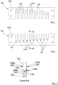
- some rooms 131 have a width extension dimension 133 less than that of other rooms 131, or vice versa.
- the chambers 131 corresponding to low notes, i.e. holes 1 to 6 have a width extension dimension 133 smaller than the width extension dimension 133 of the other chambers 131.
- the narrower the chamber 131 the more easily the aspirated reed 121 vibrates when the user blows to vibrate the aspirated reed 121.
- the air flow is more compact, more compressed, which both blocks the blown reed 111 more easily and more quickly and makes the aspirated reed 121 react more easily and more quickly.
- these chambers 131 whose width extension dimension 133 is reduced have thicker side walls 137.
- these walls 137 include bevels 146 on their surfaces facing the inside of the chamber 131 considered as illustrated in Figures 8 and 9 .
- This beveled shape 146 allows the air flow 170 to be accompanied in the chamber 131, towards the upper part 139 of the chamber 131, preferably like the ramp formed by the advance of material 140.
- These bevels 146 extend from a proximal part of the opening 135 towards the bottom 136 of the chamber 131.
- the chambers 131 corresponding to high notes, i.e. holes 7 to 10 have a width extension dimension 133 greater than the width extension dimension 133 of the other chambers 131. This makes it possible to promote the vibration of the blown reed 111 during suction by use, thus creating a negative pressure in the chamber 131.
- the present invention has been achieved by advantageously choosing a width 133 of chamber 131 which depends on the difficulty of reaching the note considered, while ensuring that this does not hinder the production of other notes of this same chamber 131 considered.
- chamber 7 for example is much wider than the others, because it is the one in which the vibration, also called triggering, of the blown reed 121 while sucking is the most difficult in the absence of the present invention.
- the chambers 8, 9 and 10 are preferably narrower than the chamber 7 on the one hand to maximize the space of the chamber 7, and on the other hand because enlarging the width of the chambers 131 means reducing the thickness of the walls 137, which makes the timbre of the notes higher. Since these are already very high notes from the chamber 8, the present invention is advantageous.
- these chambers 131 whose width is enlarged have thinner side walls. These walls include edges 147, otherwise called recesses, at the level of the opening 135 of the chamber 131 considered. This makes it possible to maintain a surface in contact with the user's mouth identical to what he is used to so as not to disturb the user's habits.
- each material advance 140 extends from the bottom 136 of its chamber 131 towards the entrance of its chamber 135.
- Each material advance 140 has an extension dimension in thickness, in width 142 and in length 141.
- the extension dimension in width 142 of each material advance is equal to the extension dimension in width 133 of the chamber 131 considered. It will be noted that the extension dimension in thickness of the material advance 140 is less than or equal to the extension dimension in thickness 134 of the chamber 131, that is to say of the bed base 130.
- the thickness extension dimension of some, preferably all, of the material advances 140 decreases from the bottom 136 of its chamber 131 and the entrance 135 of its chamber 131. This then defines a ramp as illustrated in the figures 4 And 7 .
- the proximal portion of the material advance 140 relative to the bottom 136 of the chamber 131 has a thickness extension dimension greater than the thickness extension dimension of the distal portion of the material advance 140 relative to the bottom 136 of the chamber 131, as illustrated in figures 15, 16 And 17 for example.
- the distal portion of the material advance also called the end 140c of the material advance, is arranged between the bottom 136 of the chamber 131 and the opening 135 of the chamber 131.
- the end 140c of the material advance 140 is distant from the opening 135 and the bottom 136 of the chamber 131.
- the end 140c of the material advance 140 is arranged in the chamber 131 so as to allow the passage of an air flow via the corresponding suction reed 121.
- the thickness extension dimension of each material advance 140 is constant over its entire length extension dimension 141.
- each material advance 140 has a length extension dimension 141 extending from the bottom 136 of the chamber 131 towards the opening 135 of the chamber 131.
- this length extension dimension 141 is proportional to the length extension dimension 132 of the chamber 131.
- the length extension dimension 141 of a material advance 140 is proportional to the length extension dimension of the aspirated reed 121 associated with said material advance 140 considered.
- each chamber 131 has an air passage 138a for its aspirated reed 121 and an air passage 139a for its blown reed 111.
- the air passage 139a for the blown reed 111 includes the oscillatory space 112 of the blown reed 111 considered.
- the air passage 138a for the aspirated reed 121 includes the oscillatory space 122 of the aspirated reed 121 considered.
- the air passage 139a for the blown reed 111 has length and width extension dimensions respectively greater than the length and width extension dimensions of the blown reed 111 considered.
- the air passage 138a for the aspirated reed 121 has extension dimensions in length and width respectively greater than the extension dimensions in length and width of the aspirated reed 121 considered.
- the material advance 140 comprises a portion extending parallel to the air passage 138a for the aspirated reed 121, advantageously, the material advance 140 at least partially obstructs the air passage 138a for the aspirated reed 121 considered.
- each material advance is configured to come into direct contact, preferably directly, with the aspirated reed 121 corresponding to its chamber 131.
- the material advance 140 is configured to be in direct contact with at least part of the aspirated reed 121, that is to say that there is no solid material between the material advance 140 and the aspirated reed 121 considered.
- this allows the material advance 140 to reduce the oscillatory space 122 of the aspirated reed 121 by generating a set of pressures inside the chamber 131, advantageously when the user aspirates from the chamber 131 of said aspirated reed 121, preferably by positioning his tongue so as to oscillate the blown reed 111.
- the suction produces a note different from that associated with the aspirated reed 121.
- the user can vibrate the blown reed 111 by sucking using the present invention.
- the present invention limits the oscillation of the aspirated reed 121 in this configuration, which therefore allows the user to more easily oscillate the blown reed 111 by sucking. Indeed, the sucked air then passes through the blown reed 111, causing it to vibrate since the sucked reed 121 is blocked by the pressure play created in the chamber 131 and previously explained.
- This advance of material 140 is advantageously arranged between a portion of the sucked reed 121 and the interior of the chamber 131.
- each material advance has an inner face 140a facing the inside of a chamber 131, and an outer face 140b facing the outside of a chamber 131, facing, preferably directly, the sucked reed 121.
- each outer face 140b of some or all of the material advances 140 may comprise a protuberance 143.
- This protuberance 143 has dimensions proportional to the extension dimensions of the material advance 140 to which it corresponds, that is to say on which it is arranged.
- Each of these protuberances 143 is configured to improve the insulation of the chamber 131 to which the material advance 140 corresponds.
- the length extension dimension 144 of a protuberance 143 is advantageously proportional to the length extension dimension 141 of the material advance 140 supporting it.
- each protuberance comes to the level of the base of the aspirated reed 111 corresponding to the chamber 131 considered.
- each reed whether blown 111 or aspirated 121, has a longitudinal body comprising a head and a base corresponding to a part secured to the corresponding support plate 110 or 120. It is the head which corresponds to the oscillating end of the reed.
- a reed can be considered as a vibrating beam, one end of which is fixedly mounted, called the base, on a plate and the other end of which, called the head, is free to oscillate in an oscillatory space.
- These protuberances 143 are configured and positioned to come into view, preferably directly, of the base of the aspirated reeds 121 so as to improve the confinement of the air 170 in the chamber 131 and thus reduce any leakage. It is surprising to note that the quality and control of the circulation of the air 170 in a harmonica, in particular in a chamber 131, is a function of the geometric configuration of the chamber 131 and the quality of the insulation so as to favor certain paths instead of others, for the air 170 whether it is blown or aspirated.
- these protrusions 143 make it possible to further limit the passage of the air 170 through the base of the sucked reed 121, and therefore to improve the confinement of the air 170 and thus to compact the air flow 170 more effectively.
- these protrusions 141 make it possible to reduce the oscillatory space 122 of the sucked reed 121, and therefore to help to block it, and to trigger the blown reed 111.
- these protuberances 141 also make it possible to limit the twist effect, or even eliminate it.
- the twist effect is an oscillatory phenomenon occurring at the level of the reeds. For example, when the user sucks to trigger a blown reed 111, it happens quite often with the harmonicas of the prior art that the sucked reed 121 begins to twist, that is to say to vibrate not in its length extension dimension, but in its width extension dimension, which produces a very high note which is added to the note produced by the blown reed 111. This twist effect is due to the air 170 which escapes through the sides of the base of the sucked reed 121.
- the bed base 130 may be flexible, that is to say comprise a material having a hardness coefficient along an axis normal to the upper face of the bed base of between 15A and 100A according to the Shore A scale.
- This flexibility of the 130 soundboard makes it possible to increase the air confinement effect when securing the various elements of the 100 harmonica, for example using screws.
- the flexibility of the box spring 130 makes it possible to further improve the confinement of air in the rooms 131 by acting as a locally deformed seal, for example.
- the bed base 130 has a flexibility greater than the flexibility of the first plate 110 and the second plate 120.
- the bed base 130 has a hardness coefficient along an axis normal to its upper face 130a lower than the hardness coefficients along axes normal to the main surfaces of the first 110 and second 120 plates.
- the flexible nature of the soundboard 130 according to the present invention limits, or even prevents, air leaks between the soundboard 130 and the first 110 and second 120 plates. Since these are very often non-flat, the flexibility of the soundboard 130 greatly contributes to the sealing of the instrument, and therefore to the management of a more compact air flow 170 in the chamber 131.
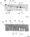
- the harmonica 100 further comprises an additional plate 150.
- the figure 10 illustrates an embodiment of this additional plate 150.
- This additional plate 150 is intended to be arranged above the first plate 110.
- This additional plate 150 comprises a plurality of additional material projections 155, and preferably lights 153 intended to allow the passage of air 170, and preferably the oscillation of the blown reeds 111.
- this additional plate 150 also comprises a plurality of lugs 151.
- each additional material advance 155 helps minimize air passing through the base and along a portion of blown reed 111 when the user sucks to trigger blown reed 111.
- each additional material advance 155 helps to compact and direct air more directly toward the end of blown reed 111, which triggers all the more easily.
- each additional material advance 155 helps minimize air passing through the base and along a portion of the blown reed 111 when the user blows to trigger the aspirated reed 121.
- each additional material advance 155 helps to compact and direct air more directly toward the end of the aspirated reed 121, which triggers all the more easily.
- These additional material advances 155 may have a variable length extension dimension depending on the desired effect. This dimension is advantageously proportional to the length extension dimension of the blown reed 111 considered.
- the obturations thus created facing the base of the blown reed 111 allow compression of the air at this location. This promotes the vibration of the end of the blown reed 111 without hindering the length of the blown reed 111 set into vibration, thus avoiding modifying its timbre.
- the lights 153 also have a variable length extension dimension depending on the desired effect. This dimension is again advantageously proportional to the length extension dimension of the blown reed 111 considered.
- FIG 10 illustrates the internal surface 154 of the additional plate 150.
- This internal surface 154 is intended to be opposite and preferably in contact with the upper face of the first plate 110 so that the additional material projections 155 are opposite the blown reeds 111.
- this additional plate 150 makes it possible to limit air leaks at the base of the blown reeds 111 and preferably over part of their length extension dimension.
- each advance of additional material 155 comprises a portion extending parallel to the air passage 139a for the blown reed 111, advantageously, each advance of additional material 155 at least partially obstructs the air passage 139a for the blown reed 111 considered.
- each additional material advance 155 comprises an inner face 155a and an outer face 155b.
- the inner face 155a of each additional material advance 155 is intended to be opposite at least a portion of a blown reed 111.
- the inner face 155a of each additional material advance 155 is carried by the inner surface 154 of the additional plate 150.
- the outer face 155b of each additional material advance 155 is intended to be opposite at least a portion of the cover 160.
- these additional material advances 155 play a similar role for the blown reeds 111 to the role played by the material advances 140 for the aspirated reeds 121.
- the distal portion of the additional material advance 155 is arranged between the opening 135 of the chamber 131 and the bottom 136 of the chamber 131.
- the end 155c of the additional material advance 155 is distant from the bottom 136 and from the opening 135 of the chamber 131.
- the end 155c of the additional material advance 155 is arranged in the chamber 131 so as to allow the passage of an air flow via the corresponding blown reed 111.
- each additional material advance 155 may comprise on its internal face 155a at least one lug 151.
- the additional plate 150 comprises a plurality of lugs 151.
- each lug 151 is configured to come opposite a portion of a blown reed 111.
- each lug 151 makes it possible to minimize the air passing through the base and along a portion of the blown reed 111 when the user sucks to trigger the blown reed 111.
- each lug 151 helps to compact and direct the air more directly towards the end of the blown reed 111, which is triggered all the more easily.
- each lug 151 is configured to come opposite a portion of a blown reed 111.
- each lug 151 makes it possible to minimize the air passing through the base and along a portion of blown reed 111 when the user blows to trigger the aspirated reed 121.
- each lug 151 helps to compact the air and redirect the air more quickly to the end of the aspirated reed 121, which triggers all the more easily.
- the lugs 151 also make it possible to limit the twisting effect, or even eliminate it, like the protuberances for the aspirated reeds. Indeed, when the user blows to trigger a aspirated reed 121, it happens quite often with the harmonicas of the prior art that the blown reed 111 begins to twist, that is to say to vibrate not in its lengthwise extension dimension, but in its widthwise extension dimension, which here again produces a very high-pitched note which is added to the note produced by the aspirated reed 121. This twisting effect is also due to the air which 170 escapes through the sides of the base of the blown reed 111, very close to the opening 135 of the chamber 131.
- each lug 151 is configured to reduce the oscillatory space 112 of a blown reed 111 when the user blows into the chamber 131 of said blown reed 111 to vibrate the aspirated reed 121. And this preferably when the user positions his tongue so as to oscillate the aspirated reed 121, that is to say when the user positions his tongue so as to minimize the space available for air to pass between it and the palate, whether by moving the back of the tongue back toward the throat, or by moving the middle part of the tongue forward toward the teeth.
- these lugs 151 play a similar role for the blown reeds 111 to the role played by the protuberances 143, for the aspirated reeds 121.
- the additional material advances 155 and the lugs 151 play a similar role for the blown reeds 111 to the role played by the material advances 140 and the protuberances 143 for the aspirated reeds 121.
- each lug 151 is configured to come into direct contact, preferably directly, with the blown reed 111 corresponding to its chamber 131.
- each lug 151 is configured to be in direct contact with at least part of the blown reed 111, that is to say that there is no solid material between the lug 151 and the blown reed 111 considered.
- this allows the lug 151 to reduce the oscillatory space 112 of the blown reed 111 by generating a set of pressures inside the chamber 131, advantageously when the user blows from the chamber 131 of said blown reed 111, preferably by positioning his tongue so as to oscillate the sucked reed 121.
- each lug 151 extends from the entrance 135 of each chamber 131 towards the bottom 136 of each chamber 131 according to a length extension dimension 152 as illustrated in figure 10 .
- this length extension dimension 152 is proportional to the length extension dimension 132 of the chamber 131 considered, and therefore of the blown reed 111 considered.
- this length extension dimension 152 is a function of the desired effect, that is to say the phenomenon that one wishes to promote.
- the length extension dimensions 152 of the lugs 151 are configured to meet the needs of the user.
- the additional material projection 155 and/or the lug 151 of the chamber 7 may be lengthened or thickened in order to further facilitate the triggering of the blown reed 111 by suction.
- each lug 151 extends at least partly into the air passage 139a for a blown reed 111. This makes it possible to increase the sealing of said air passage 139a, and therefore of the chamber 131.
- the present invention advantageously takes advantage of a set of pressures established in the chamber 131 and making it possible to block the vibration of a reed while allowing the vibration of the complementary reed.
- This pressure game is based on the formation of an overpressure in the chamber 131 at the level of the blown reed 111 when the user blows in a configuration intended to vibrate the aspirated reed 121.
- the blowing creates an overpressure in the chamber 131.
- the overpressure at the level of the blown reed 111 blocks the latter, while the overpressure at the level of the aspirated reed 121 will vibrate the latter.
- the air circuit 170 in the chamber 131 in this configuration is of less resistance passing via the aspirated reed 121 than via the blown reed 111. Consequently, the blowing makes it possible to vibrate the aspirated reed 121.
- the additional plate 150 makes it possible to limit air leaks at the base of the blown reed 111, and therefore to compact the air flow 170 in the chamber 131 when the user blows to trigger the sucked reed 121.
- the additional plate 150 also makes it possible to limit, or even eliminate, the twisting effect.
- the additional plate 150 allows, when the user blows to trigger the aspirated reed 121, to reduce the oscillatory space 112 of the blown reed 111 and therefore helps to block it and trigger the aspirated reed 121.
- the present invention facilitates the triggering, that is, the setting into vibration, of the "opposite reed", the reed blown by sucking, or the reed sucked by blowing.
- FIGs 11 to 14 illustrate normal triggering situations and opposite triggering situations.
- the figure 11 illustrates the case where the user blows into the chamber vibrating the blown reed.
- the figure 12 illustrates the case where the user sucks from the chamber causing the sucked reed to vibrate.
- FIG 13 illustrates the opposite situation to that of the figure 11 .
- FIG 13 illustrates the case where the user blows into the chamber so as to vibrate the aspirated reed.
- FIG 14 illustrates the opposite situation to that of the figure 12 .
- FIG 14 illustrates the case where the user sucks from the chamber so as to vibrate the blown reed.
- the present invention facilitates the handling of a harmonica and allows experienced players to manipulate notes not present on the instrument and this in a simple, easy and reproducible manner. Indeed, the question of reproducibility is essential.
- the present invention reduces the number of parameters influencing the obtaining or not of these particular notes.
- the cooperation between the additional plate with the first plate is similar to the cooperation of the soundboard according to the present invention with the second plate. It is the implementation of the same inventive concept applied symmetrically to two elements of the harmonica which makes it possible to achieve this ease of play and this reproducibility.
- This reproducibility is in particular linked to the improvement of the partitioning of the chambers, that is to say to the improvement of the control of the circulation of air in the chambers.
- the present invention makes it easier to obtain certain musical notes, for example upon purchasing the instrument, and advantageously without requiring long and difficult learning for the user.
- each element of the present invention provides something independently of the others, and combined together they maximize the playability of the harmonica according to the present invention.
- each element of the present invention improves the sealing inside the chamber and compacts the airflow a little more, so the pressure games are sharper, and therefore the reeds more responsive.
- the soundboard and the additional plate according to the present invention have technical advantages independently of each other, and combined together they maximize the ease of playing of the harmonica according to the present invention.
- the soundboard and the additional plate act in synergy with each other to improve the sealing inside the chamber and compact the air flow a little more, so the pressure games are sharper, and therefore the reeds more responsive.
- the harmonica according to the present invention may either comprise one of the soundboard and the additional plate, or comprise the soundboard and the additional plate.
Landscapes
- Physics & Mathematics (AREA)
- Engineering & Computer Science (AREA)
- Acoustics & Sound (AREA)
- Multimedia (AREA)
- Mattresses And Other Support Structures For Chairs And Beds (AREA)
- Toys (AREA)
- Transition And Organic Metals Composition Catalysts For Addition Polymerization (AREA)
- Organic Insulating Materials (AREA)
- Inorganic Insulating Materials (AREA)
- Display Devices Of Pinball Game Machines (AREA)
- Auxiliary Devices For Music (AREA)
- Professional, Industrial, Or Sporting Protective Garments (AREA)
- Preliminary Treatment Of Fibers (AREA)
- Nozzles For Electric Vacuum Cleaners (AREA)
- Compressors, Vaccum Pumps And Other Relevant Systems (AREA)
Claims (15)
- Mundharmonika (100), vorzugsweise diatonisch, die mindestens Folgendes umfasst:a. einen Kamm (130), der eine Vielzahl von Kammern (131) umfasst, von denen jede eine Öffnung (135) umfasst, die dazu konfiguriert ist, den Atem eines Benutzers passieren zu lassen, wobei jede Kammer (131) einen Schwingungsraum (112) für eine Blaszunge (111) und einen Schwingungsraum (122) für eine Ziehzunge (121) definiert, wobei die Blaszunge (111) und die Ziehzunge (121) jeder Kammer (131) ein komplementäres Stimmzungenpaar definieren;b. eine erste Platte (110), die eine Vielzahl von Blaszungen (111) umfasst, wobei die erste Platte (110) gegenüber einer ersten Fläche, vorzugsweise einer oberen Fläche (130a), des Kamms (130) angeordnet ist, wobei jede Blaszunge (111) der Vielzahl von Blaszungen (111) dazu konfiguriert ist, in ihrem Schwingungsraum (112) zu schwingen, wenn der Benutzer mindestens in die Kammer (131) bläst, die den Schwingungsraum (112) definiert;c. eine zweite Platte (120), die eine Vielzahl von Ziehzungen (121) umfasst, wobei die zweite Platte (120) gegenüber einer zweiten Fläche, vorzugsweise einer unteren Fläche (130b), des Kamms (130) angeordnet ist, wobei jede Ziehzunge (121) der Vielzahl von Ziehzungen (121) dazu konfiguriert ist, in ihrem Schwingungsraum (122) zu schwingen, wenn der Benutzer Luft mindestens aus der Kammer (131) ansaugt, die den Schwingungsraum (122) definiert;wobei die Mundharmonika (100) dadurch gekennzeichnet ist, dass:d. ein Teil mindestens der Kammern (131) der Vielzahl von Kammern (131) mindestens einen Materialvorsprung (140) umfasst, wobei jeder Materialvorsprung (140) mindestens teilweise gegenüber einem Abschnitt einer Ziehzunge (121) angeordnet und dazu konfiguriert ist, den Schwingungsraum (122) der Ziehzunge (121) zu reduzieren und die Schwingung der Blaszunge (111) des komplementären Paars der Ziehzunge (121) zu ermöglichen, wenn der Benutzer Luft aus der Kammer (131) der Ziehzunge (121) ansaugt, indem er vorzugsweise seine Zunge so positioniert, dass die Blaszunge (111) schwingt; und/odere. dass sie mindestens eine zusätzliche Platte (150) umfasst, die gegenüber einer Fläche der ersten Platte (110), vorzugsweise gegenüber einer Fläche der ersten Platte (110), die der Fläche der ersten Platte (110) gegenüber der ersten Fläche des Kamms (130) gegenüberliegt, angeordnet ist und mindestens eine Vielzahl von zusätzlichen Materialvorsprüngen (155) umfasst, wobei jeder zusätzliche Materialvorsprung (155) mindestens teilweise gegenüber einem Abschnitt einer Blaszunge (111) angeordnet und dazu konfiguriert ist, den Schwingungsraum (112) der Blaszunge (111) zu reduzieren und die Schwingung der Ziehzunge (121) des komplementären Paars der Blaszunge (111) zu ermöglichen, wenn der Benutzer in die Kammer (131) der Blaszunge (111) bläst, indem er vorzugsweise seine Zunge so positioniert, dass die Ziehzunge (121) schwingt.
- Mundharmonika (100) nach dem vorhergehenden Anspruch, wobei ein Teil mindestens der Kammern (131) der Vielzahl von Kammern (131) eine Breitenerstreckungsabmessung (133) aufweist, die größer ist als die Breitenerstreckungsabmessung (133) eines anderen Teils mindestens der Kammern (131) der Vielzahl von Kammern (131).
- Mundharmonika (100) nach einem der vorhergehenden Ansprüche, wobei jeder Materialvorsprung (140) sich vom Boden (136) seiner Kammer (131) bis zur Öffnung (135) seiner Kammer (131) erstreckt und wobei jeder Materialvorsprung (140) vorzugsweise eine Dickenerstreckungsabmessung umfasst, wobei die Dickenerstreckungsabmessung sich vom Boden (136) seiner Kammer (131) bis zur Öffnung (135) seiner Kammer (131) verringert und vorzugsweise eine Schräge definiert.
- Mundharmonika (100) nach einem der vorhergehenden Ansprüche, wobei ein Teil mindestens der Materialvorsprünge (140) mit dem Boden (136) ihrer Kammer (131) ein Plateau (148) definiert, wobei sich das Plateau (148) gemäß einer Ebene orthogonal zur Erstreckungsebene der Seitenwände (137) ihrer Kammer (131) erstreckt.
- Mundharmonika (100) nach einem der vorhergehenden Ansprüche, wobei der untere Teil (138) jeder Kammer (131) der Vielzahl von Kammern (131) einen Luftkanal (138a) für eine Ziehzunge (121) umfasst, und wobei sich jeder Materialvorsprung (140) mindestens teilweise so erstreckt, dass er den Luftkanal (138a) einer Ziehzunge (121) mindestens teilweise blockiert.
- Mundharmonika (100) nach einem der vorhergehenden Ansprüche, wobei der obere Teil (139) jeder Kammer (131) der Vielzahl von Kammern (131) einen Luftkanal (139a) für eine Blaszunge (111) umfasst, und wobei sich jeder zusätzliche Materialvorsprung (155) mindestens teilweise so erstreckt, dass er den Luftkanal (139a) einer Blaszunge (111) mindestens teilweise blockiert.
- Mundharmonika (100) nach einem der vorhergehenden Ansprüche, wobei jede Kammer (131) der Vielzahl von Kammern (131) eine Breitenerstreckungsabmessung (133) und eine Längenerstreckungsabmessung (132) umfasst, und wobei jeder zusätzliche Materialvorsprung (155) eine Breitenerstreckungsabmessung, die gleich der Breitenerstreckungsabmessung ihrer Kammer (131) ist, und eine Längenerstreckungsabmessung aufweist, die kleiner als die Längenerstreckungsabmessung ihrer Kammer (131) ist, und wobei vorzugsweise das Verhältnis zwischen der Längenerstreckungsabmessung eines zusätzlichen Materialvorsprungs (155) und der Längenerstreckungsabmessung (132) seiner Kammer (131) zwischen 0,1 und 0,9, vorzugsweise zwischen 0,3 und 0,7 und vorteilhafterweise gleich 0,5, beträgt.
- Mundharmonika (100) nach einem der vorhergehenden Ansprüche, wobei jeder zusätzliche Materialvorsprung (155) eine Innenfläche (155a), die der Innenseite seiner Kammer (131) zugewandt ist, und eine Außenfläche (155b) aufweist, die der Außenseite seiner Kammer (131) zugewandt ist, und wobei jeder zusätzliche Materialvorsprung (155) mindestens eine Nase (151) umfasst, die auf seiner Innenfläche (155b) angeordnet ist,und wobei sich die Nase (151) vorzugsweise vom Einlass jeder Kammer (135) in Richtung des Bodens (136) jeder Kammer (131) in einer Längenerstreckungsabmessung (152) erstreckt,und wobei sich jede Nase (151) vorzugsweise mindestens teilweise in den Luftkanal (139a) einer Blaszunge (111) hinein erstreckt.
- Mundharmonika (100) nach einem der vorhergehenden Ansprüche, wobei jeder Materialvorsprung (140) ein Ende (140c) umfasst, das von der Öffnung (135) und vom Boden (136) seiner Kammer (131) entfernt ist,
und wobei jeder zusätzliche Materialvorsprung (155) ein Ende (155c) umfasst, das vom Boden (136) und von der Öffnung (135) seiner Kammer (131) entfernt ist. - Mundharmonika (100) nach einem der vorhergehenden Ansprüche, wobei jede Kammer (131) der Vielzahl von Kammern (131) eine Breitenerstreckungsabmessung (133) und eine Längenerstreckungsabmessung (132) umfasst, und wobei jeder Materialvorsprung (141) eine Breitenerstreckungsabmessung (142), die gleich der Breitenerstreckungsabmessung (133) ihrer Kammer (131) ist, und eine Längenerstreckungsabmessung (141) aufweist, die kleiner ist als die Längenerstreckungsabmessung (132) ihrer Kammer (131), und wobei vorzugsweise das Verhältnis zwischen der Längenerstreckungsabmessung (141) eines Materialvorsprungs (140) und der Längenerstreckungsabmessung (132) seiner Kammer (131) zwischen 0,1 und 0,9, vorzugsweise zwischen 0,2 und 0,5 und vorteilhafterweise gleich 0,33, beträgt.
- Mundharmonika (100) nach einem der vorhergehenden Ansprüche, wobei jeder Materialvorsprung (140) eine Innenfläche (140a), die der Innenseite seiner Kammer (131) zugewandt ist, und eine Außenfläche (140b) aufweist, die der Außenseite seiner Kammer (131) zugewandt ist, und wobei der Materialvorsprung (140) mindestens eine Ausbuchtung (143) umfasst, die auf seiner Außenfläche (140b) angeordnet ist,und wobei vorzugsweise die Ausbuchtung (143) eine Längenerstreckungsabmessung (144) aufweist, die proportional zur Längenerstreckungsabmessung (141) des Materialvorsprungs (140) ist, der die betrachtete Ausbuchtung (143) umfasst,und wobei sich die Ausbuchtung (143) mindestens teilweise in den Luftkanal (138a) einer Ziehzunge (121) erstreckt, und wobei sich jede Ausbuchtung (143) vom Boden (136) jeder Kammer (131) in Richtung des Einlasses (135) jeder Kammer (131) entsprechend der Längenerstreckungsabmessung (144) erstreckt.
- Mundharmonika (100) nach einem der vorhergehenden Ansprüche, wobei der Kamm (130) eine größere Flexibilität aufweist als die Flexibilität der ersten Platte (110) und die Flexibilität der zweiten Platte (120).
- Kamm (130) für eine Mundharmonika (100), vorzugsweise diatonisch, die eine erste Platte (110), die eine Vielzahl von Blaszungen (111) umfasst, und eine zweite Platte (120) umfasst, die eine Vielzahl von Ziehzungen (121) umfasst, wobei der Kamm (130) eine Vielzahl von Kammern (131) umfasst, wobei jede Kammer (131) der Vielzahl von Kammern (131) einem komplementären Stimmzungenpaar zugeordnet ist, das eine Blaszunge (111) und eine Ziehzunge (121) umfasst, wobei jede Kammer (131) der Vielzahl von Kammern (131) jeweils eine Öffnung (135) umfasst, die dazu konfiguriert ist, den Atem des Benutzers passieren zu lassen, und dazu bestimmt ist, einen Schwingungsraum (112, 122) für eine Blaszunge (111) und für eine Ziehzunge (121) zu definieren, wobei der Kamm (130) dadurch gekennzeichnet ist, dass jede Kammer (131) der Vielzahl von Kammern (131) mindestens einen Materialvorsprung (140) umfasst, wobei jeder Materialvorsprung (140) dazu bestimmt ist, mindestens teilweise gegenüber einem Abschnitt einer Ziehzunge (121) angeordnet zu sein, und dazu konfiguriert ist, den Schwingungsraum (122) der Ziehzunge (121) zu reduzieren und die Schwingung der Blaszunge (111) des komplementären Paars der Ziehzunge (121) zu ermöglichen, wenn der Benutzer Luft aus der Kammer (131) der Ziehzunge (121) ansaugt, indem er vorzugsweise seine Zunge so positioniert, dass die Blaszunge (111) schwingt.
- Zusätzliche Platte (150) für eine Mundharmonika (100), vorzugsweise diatonisch, die eine erste Platte (110), die eine Vielzahl von Blaszungen (111) umfasst, und eine zweite Platte (120) umfasst, die eine Vielzahl von Ziehzungen (121) umfasst, wobei jede Blaszunge (111) mit einer Ziehzunge (121) ein komplementäres Stimmzungenpaar bildet, wobei die zusätzliche Platte (150) dazu bestimmt ist, oberhalb der ersten Platte (110) angeordnet zu sein, und dadurch gekennzeichnet ist, dass sie mindestens eine Vielzahl von zusätzlichen Materialvorsprüngen (155) umfasst, wobei jeder zusätzliche Materialvorsprung (155) mindestens teilweise gegenüber einem Abschnitt einer Blaszunge (111) angeordnet und dazu konfiguriert ist, den Schwingungsraum (112) der Blaszunge (111) zu reduzieren und die Schwingung der Ziehzunge (121) des komplementären Paars der Blaszunge (111) zu ermöglichen, wenn der Benutzer in die Kammer (131) der Blaszunge (111) bläst, indem er vorzugsweise seine Zunge so positioniert, dass die Ziehzunge (121) schwingt.
- Kit für eine Mundharmonika (100), vorzugsweise diatonisch, die mindestens einen Kamm (130) nach Anspruch 13 und mindestens eine zusätzliche Platte (150) nach Anspruch 14 umfasst.
Applications Claiming Priority (2)
| Application Number | Priority Date | Filing Date | Title |
|---|---|---|---|
| FR2001144A FR3106925B1 (fr) | 2020-02-05 | 2020-02-05 | Harmonica perfectionné |
| PCT/EP2021/052701 WO2021156384A1 (fr) | 2020-02-05 | 2021-02-04 | Harmonica perfectionné |
Publications (3)
| Publication Number | Publication Date |
|---|---|
| EP4100944A1 EP4100944A1 (de) | 2022-12-14 |
| EP4100944B1 true EP4100944B1 (de) | 2024-11-13 |
| EP4100944C0 EP4100944C0 (de) | 2024-11-13 |
Family
ID=70614090
Family Applications (1)
| Application Number | Title | Priority Date | Filing Date |
|---|---|---|---|
| EP21702508.9A Active EP4100944B1 (de) | 2020-02-05 | 2021-02-04 | Verbesserte mundharmonika |
Country Status (10)
| Country | Link |
|---|---|
| US (2) | US11763783B2 (de) |
| EP (1) | EP4100944B1 (de) |
| JP (1) | JP7805935B2 (de) |
| KR (1) | KR20220130816A (de) |
| CN (1) | CN115104149A (de) |
| AU (1) | AU2021217772A1 (de) |
| BR (1) | BR112022015262A2 (de) |
| CA (1) | CA3165773A1 (de) |
| FR (1) | FR3106925B1 (de) |
| WO (1) | WO2021156384A1 (de) |
Families Citing this family (2)
| Publication number | Priority date | Publication date | Assignee | Title |
|---|---|---|---|---|
| FR3106925B1 (fr) * | 2020-02-05 | 2023-12-22 | Alien Beats Records | Harmonica perfectionné |
| WO2025120609A1 (en) * | 2023-12-07 | 2025-06-12 | Giries Artul | Bottle with integrated musical insturment |
Family Cites Families (19)
| Publication number | Priority date | Publication date | Assignee | Title |
|---|---|---|---|---|
| DE242031C (de) * | 1911-01-03 | 1911-12-21 | Kanzellenholzkörper für mundharmonikas u. dgl. | |
| US2473210A (en) * | 1947-04-30 | 1949-06-14 | Magnus Harmonica Corp | Harmonica and wind cell block therefor |
| US2595316A (en) * | 1948-07-13 | 1952-05-06 | Charles E Wetzler | Reed operated musical instrument |
| JPS5937825Y2 (ja) * | 1979-01-25 | 1984-10-19 | サンリ−ド工業株式会社 | ハ−モニカ |
| JPS5638385U (de) * | 1979-08-31 | 1981-04-11 | ||
| US4342250A (en) * | 1980-01-22 | 1982-08-03 | The Quaker Oats Company | Harmonica |
| US5182413A (en) * | 1991-08-26 | 1993-01-26 | Epping William R | Harmonica |
| US5739446A (en) * | 1992-05-21 | 1998-04-14 | Bahnson; Henry T. | Harmonica and method of playing same |
| JPH0950276A (ja) * | 1995-08-10 | 1997-02-18 | Yamaha Corp | ハーモニカ |
| JP3268272B2 (ja) | 1998-08-18 | 2002-03-25 | 株式会社鈴木楽器製作所 | ハーモニカ |
| US6359204B2 (en) * | 2000-02-02 | 2002-03-19 | James F. Antaki | Enhanced harmonica |
| US6518489B2 (en) * | 2001-04-12 | 2003-02-11 | William R. Epping | Harmonica comb |
| TWI256037B (en) * | 2004-10-20 | 2006-06-01 | Shiou-Shiung Lin | Mouth-organ |
| CN102214458B (zh) * | 2010-04-07 | 2012-07-18 | 陈红梅 | 24孔电声口琴 |
| JP5756735B2 (ja) | 2011-10-27 | 2015-07-29 | 株式会社トンボ楽器製作所 | クロマチックハーモニカ |
| JP3183909U (ja) * | 2013-03-26 | 2013-06-06 | 直孝 岸 | スライド式クロマチックハーモニカネット状シート付きバルブ |
| CN103226937A (zh) * | 2013-05-04 | 2013-07-31 | 陈红梅 | 一种21孔口琴 |
| CN209947419U (zh) * | 2019-05-17 | 2020-01-14 | 江苏东方乐器有限公司 | 具有磁体附接件的口琴 |
| FR3106925B1 (fr) * | 2020-02-05 | 2023-12-22 | Alien Beats Records | Harmonica perfectionné |
-
2020
- 2020-02-05 FR FR2001144A patent/FR3106925B1/fr active Active
-
2021
- 2021-02-04 KR KR1020227030749A patent/KR20220130816A/ko active Pending
- 2021-02-04 JP JP2022547909A patent/JP7805935B2/ja active Active
- 2021-02-04 WO PCT/EP2021/052701 patent/WO2021156384A1/fr not_active Ceased
- 2021-02-04 BR BR112022015262A patent/BR112022015262A2/pt unknown
- 2021-02-04 AU AU2021217772A patent/AU2021217772A1/en active Pending
- 2021-02-04 CA CA3165773A patent/CA3165773A1/fr active Pending
- 2021-02-04 US US17/797,842 patent/US11763783B2/en active Active
- 2021-02-04 EP EP21702508.9A patent/EP4100944B1/de active Active
- 2021-02-04 CN CN202180012884.0A patent/CN115104149A/zh active Pending
-
2023
- 2023-08-02 US US18/364,166 patent/US12027142B2/en active Active
Also Published As
| Publication number | Publication date |
|---|---|
| FR3106925A1 (fr) | 2021-08-06 |
| US11763783B2 (en) | 2023-09-19 |
| JP2023513199A (ja) | 2023-03-30 |
| BR112022015262A2 (pt) | 2022-09-20 |
| EP4100944C0 (de) | 2024-11-13 |
| KR20220130816A (ko) | 2022-09-27 |
| US20230096049A1 (en) | 2023-03-30 |
| CA3165773A1 (fr) | 2021-08-12 |
| US12027142B2 (en) | 2024-07-02 |
| WO2021156384A1 (fr) | 2021-08-12 |
| EP4100944A1 (de) | 2022-12-14 |
| FR3106925B1 (fr) | 2023-12-22 |
| JP7805935B2 (ja) | 2026-01-26 |
| AU2021217772A1 (en) | 2022-08-25 |
| CN115104149A (zh) | 2022-09-23 |
| US20230377539A1 (en) | 2023-11-23 |
Similar Documents
| Publication | Publication Date | Title |
|---|---|---|
| EP4100944B1 (de) | Verbesserte mundharmonika | |
| EP2561507B1 (de) | Verbesserung für eine harmonika | |
| US7705224B1 (en) | Portable travel guitar | |
| EP1461803A1 (de) | Mundstück für ein musikinstrument mit einem zungenblatt | |
| US20040194607A1 (en) | Plectrum | |
| FR2709249A1 (fr) | Appareil auditif destiné à être inséré profondément dans le conduit de l'oreille. | |
| US20080078279A1 (en) | Pitch modulator drum | |
| FR2677160A1 (fr) | Instruments de musique a cordes frottees ou pincees. | |
| CA2672592A1 (fr) | Perfectionnement pour harmonica | |
| FR2876830A1 (fr) | Harmonica | |
| EP3197321B1 (de) | Sitz mit einem trommelelement | |
| EP1301918B1 (de) | Zungeninstrument | |
| EP2529368B1 (de) | Verbesserung für eine mit einem luftverteiler ausgestattete harmonika | |
| KR100849581B1 (ko) | 오카리나 | |
| FR3026886B1 (fr) | Generateur de sons et kit musical comprenant un tel generateur de sons | |
| KR102067532B1 (ko) | 관악기 | |
| FR2643182A1 (fr) | Procede de perfectionnement d'instruments de musique de la classe des cordophones munis d'un manche et comprenant deux nappes de cordes, l'une sur la face avant et l'autre sur la face arriere du manche, ainsi que les instruments de musique realises a partir de ce procede | |
| FR2889346A1 (fr) | Sourdine de saxophone et clarinette interne | |
| CN108292495A (zh) | 改进的长笛头部接头 | |
| FR3164048A1 (fr) | Caisse de percussion | |
| FR2927817A1 (fr) | Dispositif de placement de la voix pariee et/ou chantee | |
| FR2791460A1 (fr) | Instrument de musique a percussion | |
| FR2647247A1 (fr) | Bec pour instrument a vent | |
| FR2626707A1 (fr) | Instrument a cordes pincees ou frappees muni de resonateurs a membranes | |
| WO2019002749A1 (fr) | Instrument de musique a vent a anches libres |
Legal Events
| Date | Code | Title | Description |
|---|---|---|---|
| STAA | Information on the status of an ep patent application or granted ep patent |
Free format text: STATUS: UNKNOWN |
|
| STAA | Information on the status of an ep patent application or granted ep patent |
Free format text: STATUS: THE INTERNATIONAL PUBLICATION HAS BEEN MADE |
|
| PUAI | Public reference made under article 153(3) epc to a published international application that has entered the european phase |
Free format text: ORIGINAL CODE: 0009012 |
|
| STAA | Information on the status of an ep patent application or granted ep patent |
Free format text: STATUS: REQUEST FOR EXAMINATION WAS MADE |
|
| 17P | Request for examination filed |
Effective date: 20220721 |
|
| AK | Designated contracting states |
Kind code of ref document: A1 Designated state(s): AL AT BE BG CH CY CZ DE DK EE ES FI FR GB GR HR HU IE IS IT LI LT LU LV MC MK MT NL NO PL PT RO RS SE SI SK SM TR |
|
| DAV | Request for validation of the european patent (deleted) | ||
| DAX | Request for extension of the european patent (deleted) | ||
| STAA | Information on the status of an ep patent application or granted ep patent |
Free format text: STATUS: EXAMINATION IS IN PROGRESS |
|
| 17Q | First examination report despatched |
Effective date: 20230911 |
|
| GRAP | Despatch of communication of intention to grant a patent |
Free format text: ORIGINAL CODE: EPIDOSNIGR1 |
|
| STAA | Information on the status of an ep patent application or granted ep patent |
Free format text: STATUS: GRANT OF PATENT IS INTENDED |
|
| INTG | Intention to grant announced |
Effective date: 20240703 |
|
| GRAS | Grant fee paid |
Free format text: ORIGINAL CODE: EPIDOSNIGR3 |
|
| GRAA | (expected) grant |
Free format text: ORIGINAL CODE: 0009210 |
|
| STAA | Information on the status of an ep patent application or granted ep patent |
Free format text: STATUS: THE PATENT HAS BEEN GRANTED |
|
| AK | Designated contracting states |
Kind code of ref document: B1 Designated state(s): AL AT BE BG CH CY CZ DE DK EE ES FI FR GB GR HR HU IE IS IT LI LT LU LV MC MK MT NL NO PL PT RO RS SE SI SK SM TR |
|
| REG | Reference to a national code |
Ref country code: GB Ref legal event code: FG4D Free format text: NOT ENGLISH |
|
| REG | Reference to a national code |
Ref country code: CH Ref legal event code: EP |
|
| REG | Reference to a national code |
Ref country code: IE Ref legal event code: FG4D Free format text: LANGUAGE OF EP DOCUMENT: FRENCH |
|
| REG | Reference to a national code |
Ref country code: DE Ref legal event code: R096 Ref document number: 602021021754 Country of ref document: DE |
|
| U01 | Request for unitary effect filed |
Effective date: 20241205 |
|
| U07 | Unitary effect registered |
Designated state(s): AT BE BG DE DK EE FI FR IT LT LU LV MT NL PT RO SE SI Effective date: 20241216 |
|
| U20 | Renewal fee for the european patent with unitary effect paid |
Year of fee payment: 5 Effective date: 20250226 |
|
| PG25 | Lapsed in a contracting state [announced via postgrant information from national office to epo] |
Ref country code: IS Free format text: LAPSE BECAUSE OF FAILURE TO SUBMIT A TRANSLATION OF THE DESCRIPTION OR TO PAY THE FEE WITHIN THE PRESCRIBED TIME-LIMIT Effective date: 20250313 Ref country code: HR Free format text: LAPSE BECAUSE OF FAILURE TO SUBMIT A TRANSLATION OF THE DESCRIPTION OR TO PAY THE FEE WITHIN THE PRESCRIBED TIME-LIMIT Effective date: 20241113 |
|
| PG25 | Lapsed in a contracting state [announced via postgrant information from national office to epo] |
Ref country code: ES Free format text: LAPSE BECAUSE OF FAILURE TO SUBMIT A TRANSLATION OF THE DESCRIPTION OR TO PAY THE FEE WITHIN THE PRESCRIBED TIME-LIMIT Effective date: 20241113 |
|
| PG25 | Lapsed in a contracting state [announced via postgrant information from national office to epo] |
Ref country code: NO Free format text: LAPSE BECAUSE OF FAILURE TO SUBMIT A TRANSLATION OF THE DESCRIPTION OR TO PAY THE FEE WITHIN THE PRESCRIBED TIME-LIMIT Effective date: 20250213 |
|
| PG25 | Lapsed in a contracting state [announced via postgrant information from national office to epo] |
Ref country code: GR Free format text: LAPSE BECAUSE OF FAILURE TO SUBMIT A TRANSLATION OF THE DESCRIPTION OR TO PAY THE FEE WITHIN THE PRESCRIBED TIME-LIMIT Effective date: 20250214 |
|
| PGFP | Annual fee paid to national office [announced via postgrant information from national office to epo] |
Ref country code: CH Payment date: 20250301 Year of fee payment: 5 |
|
| PG25 | Lapsed in a contracting state [announced via postgrant information from national office to epo] |
Ref country code: PL Free format text: LAPSE BECAUSE OF FAILURE TO SUBMIT A TRANSLATION OF THE DESCRIPTION OR TO PAY THE FEE WITHIN THE PRESCRIBED TIME-LIMIT Effective date: 20241113 |
|
| PGFP | Annual fee paid to national office [announced via postgrant information from national office to epo] |
Ref country code: GB Payment date: 20250221 Year of fee payment: 5 |
|
| PG25 | Lapsed in a contracting state [announced via postgrant information from national office to epo] |
Ref country code: RS Free format text: LAPSE BECAUSE OF FAILURE TO SUBMIT A TRANSLATION OF THE DESCRIPTION OR TO PAY THE FEE WITHIN THE PRESCRIBED TIME-LIMIT Effective date: 20250213 |
|
| PG25 | Lapsed in a contracting state [announced via postgrant information from national office to epo] |
Ref country code: SM Free format text: LAPSE BECAUSE OF FAILURE TO SUBMIT A TRANSLATION OF THE DESCRIPTION OR TO PAY THE FEE WITHIN THE PRESCRIBED TIME-LIMIT Effective date: 20241113 |
|
| PG25 | Lapsed in a contracting state [announced via postgrant information from national office to epo] |
Ref country code: SK Free format text: LAPSE BECAUSE OF FAILURE TO SUBMIT A TRANSLATION OF THE DESCRIPTION OR TO PAY THE FEE WITHIN THE PRESCRIBED TIME-LIMIT Effective date: 20241113 |
|
| PG25 | Lapsed in a contracting state [announced via postgrant information from national office to epo] |
Ref country code: CZ Free format text: LAPSE BECAUSE OF FAILURE TO SUBMIT A TRANSLATION OF THE DESCRIPTION OR TO PAY THE FEE WITHIN THE PRESCRIBED TIME-LIMIT Effective date: 20241113 |
|
| PG25 | Lapsed in a contracting state [announced via postgrant information from national office to epo] |
Ref country code: MC Free format text: LAPSE BECAUSE OF FAILURE TO SUBMIT A TRANSLATION OF THE DESCRIPTION OR TO PAY THE FEE WITHIN THE PRESCRIBED TIME-LIMIT Effective date: 20241113 |
|
| PLBE | No opposition filed within time limit |
Free format text: ORIGINAL CODE: 0009261 |
|
| STAA | Information on the status of an ep patent application or granted ep patent |
Free format text: STATUS: NO OPPOSITION FILED WITHIN TIME LIMIT |
|
| 26N | No opposition filed |
Effective date: 20250814 |
|
| PG25 | Lapsed in a contracting state [announced via postgrant information from national office to epo] |
Ref country code: IE Free format text: LAPSE BECAUSE OF NON-PAYMENT OF DUE FEES Effective date: 20250204 |
|
| REG | Reference to a national code |
Ref country code: CH Ref legal event code: U11 Free format text: ST27 STATUS EVENT CODE: U-0-0-U10-U11 (AS PROVIDED BY THE NATIONAL OFFICE) Effective date: 20260301 |