EP4100676B1 - Dispositif d'inspection et unité d'inspection - Google Patents
Dispositif d'inspection et unité d'inspection Download PDFInfo
- Publication number
- EP4100676B1 EP4100676B1 EP21707899.7A EP21707899A EP4100676B1 EP 4100676 B1 EP4100676 B1 EP 4100676B1 EP 21707899 A EP21707899 A EP 21707899A EP 4100676 B1 EP4100676 B1 EP 4100676B1
- Authority
- EP
- European Patent Office
- Prior art keywords
- inspection device
- axis
- rotation
- circumference
- magnets
- Prior art date
- Legal status (The legal status is an assumption and is not a legal conclusion. Google has not performed a legal analysis and makes no representation as to the accuracy of the status listed.)
- Active
Links
Images

Classifications
-
- F—MECHANICAL ENGINEERING; LIGHTING; HEATING; WEAPONS; BLASTING
- F16—ENGINEERING ELEMENTS AND UNITS; GENERAL MEASURES FOR PRODUCING AND MAINTAINING EFFECTIVE FUNCTIONING OF MACHINES OR INSTALLATIONS; THERMAL INSULATION IN GENERAL
- F16L—PIPES; JOINTS OR FITTINGS FOR PIPES; SUPPORTS FOR PIPES, CABLES OR PROTECTIVE TUBING; MEANS FOR THERMAL INSULATION IN GENERAL
- F16L55/00—Devices or appurtenances for use in, or in connection with, pipes or pipe systems
- F16L55/26—Pigs or moles, i.e. devices movable in a pipe or conduit with or without self-contained propulsion means
- F16L55/28—Constructional aspects
-
- F—MECHANICAL ENGINEERING; LIGHTING; HEATING; WEAPONS; BLASTING
- F16—ENGINEERING ELEMENTS AND UNITS; GENERAL MEASURES FOR PRODUCING AND MAINTAINING EFFECTIVE FUNCTIONING OF MACHINES OR INSTALLATIONS; THERMAL INSULATION IN GENERAL
- F16L—PIPES; JOINTS OR FITTINGS FOR PIPES; SUPPORTS FOR PIPES, CABLES OR PROTECTIVE TUBING; MEANS FOR THERMAL INSULATION IN GENERAL
- F16L55/00—Devices or appurtenances for use in, or in connection with, pipes or pipe systems
- F16L55/26—Pigs or moles, i.e. devices movable in a pipe or conduit with or without self-contained propulsion means
-
- H—ELECTRICITY
- H04—ELECTRIC COMMUNICATION TECHNIQUE
- H04N—PICTORIAL COMMUNICATION, e.g. TELEVISION
- H04N23/00—Cameras or camera modules comprising electronic image sensors; Control thereof
- H04N23/60—Control of cameras or camera modules
-
- H—ELECTRICITY
- H04—ELECTRIC COMMUNICATION TECHNIQUE
- H04N—PICTORIAL COMMUNICATION, e.g. TELEVISION
- H04N5/00—Details of television systems
- H04N5/76—Television signal recording
-
- H—ELECTRICITY
- H04—ELECTRIC COMMUNICATION TECHNIQUE
- H04N—PICTORIAL COMMUNICATION, e.g. TELEVISION
- H04N7/00—Television systems
- H04N7/18—Closed-circuit television [CCTV] systems, i.e. systems in which the video signal is not broadcast
- H04N7/188—Capturing isolated or intermittent images triggered by the occurrence of a predetermined event, e.g. an object reaching a predetermined position
-
- F—MECHANICAL ENGINEERING; LIGHTING; HEATING; WEAPONS; BLASTING
- F16—ENGINEERING ELEMENTS AND UNITS; GENERAL MEASURES FOR PRODUCING AND MAINTAINING EFFECTIVE FUNCTIONING OF MACHINES OR INSTALLATIONS; THERMAL INSULATION IN GENERAL
- F16L—PIPES; JOINTS OR FITTINGS FOR PIPES; SUPPORTS FOR PIPES, CABLES OR PROTECTIVE TUBING; MEANS FOR THERMAL INSULATION IN GENERAL
- F16L2101/00—Uses or applications of pigs or moles
- F16L2101/30—Inspecting, measuring or testing
Definitions
- the present invention relates to an inspection device for examining pipelines, comprising a sensor carrier which can be rolled through the pipeline during operation, which is provided with an at least substantially circular circumference in a section running transversely to an axis of rotation and which has at least one sensor unit.
- Such spherical inspection devices move irregularly in the pipeline due to the dynamics of the transported medium and the pipeline path; they can jump, rotate or slide around all three spatial axes. These irregular movements result in a very high level of effort in data interpretation, to the point of making it impossible due to low signal-to-noise ratios. This applies both to the interpretation of the defect data and the position of the defects.
- Such a state of the art can be found, for example, in the EP 2902690 B1 or the US 2008204008 A1 described.
- CN 105043312 discloses an inspection device having a plurality of ultrasonic sensors distributed over the outer surface of the ball-shaped inspection device.
- the EP 1 215 436 A2 discloses a pipeline pig with an annular magnet holder designed with an oversize relative to a pipeline to be pigged.
- the sensor carrier comprises a plurality of stabilizing means arranged along the circumference, wherein a plurality of magnets radially spaced from the axis of rotation are provided as stabilizing means, wherein a respective magnetic field of the magnets interacts with the pipeline wall during operation for a more stable run.
- the stabilizing means or means promote or improve a movement of the inspection device in a direction at least substantially transverse to a selected axis of rotation and a rolling on the circumference during operation.
- the rolling takes place in particular along the pipeline axis during operation, wherein the axis of rotation is preferably at least substantially transverse to it when it forms an angle of +/- 10° with the pipeline axis.
- An improvement in the rolling behavior is particularly present when the rolling of the inspection device around a circumference in the pipeline around the selected axis of rotation can be carried out better, ie more evenly or at all, than around another circumference with a further axis of rotation lying transversely or at an angle to the selected axis of rotation.
- the rolling of the device takes place in particular on the part or parts of the inspection device that form the circumference.
- the stabilizing means or means are in particular arranged away from the axis of rotation, i.e. in or on the outer circumference, possibly forming the outer circumference and, through the force they emit or the impulse they generate, ensuring a more stable rolling of the inspection device.
- the stabilizing means(s) arranged along the circumference promote movement when, for example, maintaining an orientation of a rotation axis of the device is stabilized, for example by increasing a generated angular momentum or by means for adhering to the pipeline wall.
- the latter means support a gravity-induced movement of the inspection device in the pipeline along the 0 o'clock or 6 o'clock position.
- a circular circumference is given when the inspection device can roll on a flat plane on the circular circumference without acceleration peaks interfering with the measurement.
- a circular circumference is therefore a circumference that is exactly circular or, for example, approximately circular due to a polygon.
- An ellipsoidal shape is a shape that deviates from an ellipsoid either by exactly one ellipsoid or by a few cm, ie less than 10 cm, preferably less than 5 cm.
- the stabilizing means can form the circumference or be arranged close to the circumference; for example, the cut running transversely to the axis of rotation can run through the stabilizing means, which are in particular spaced radially from the axis of rotation, or run along them.
- one or more weights radially spaced from the axis of rotation and several magnets radially spaced from the axis of rotation are provided as stabilizing means, wherein a respective magnetic field of the magnet(s) interacts with the pipeline wall during operation.
- the magnets have a higher weight than areas of the inspection device that are radially offset from the axis of rotation. While a weight already increases the generated angular momentum and thus promotes compliance with the direction of the axis of rotation, one or more magnets in the circumference or along the circumference of the inspection device not only increase the angular momentum but also at least increase the adhesion between the wall and the device and thus greatly promote slip-free running.
- the magnetizable material of the pipeline is magnetized and demagnetized again when the magnet is removed during rolling, which creates eddy currents that counteract an increase in the running speed of the device and thus greatly improve the running behavior.
- the magnets which themselves can also represent additional weights along the circumference, thus promote a more stable running of the device on the one hand due to gravity and on the other hand due to the magnetic interaction.
- Permanent magnets are preferably used as magnets. However, electromagnets can also be used, so that the strength of the interaction with the wall of the pipeline can be adjusted by an appropriate control device.
- the north-south alignment of the permanent magnets preferably runs parallel to the axis of rotation, so that no forces occur on the circumference in the tangential direction of the circumference.
- one or more or even all of the magnets designed as permanent magnets can be aligned radially to the axis of rotation with their north-south alignment, so that no tangential forces arise.
- This rotationally symmetrical arrangement of the magnets in the stationary state does not generate any tangential forces, it allows for easier rolling and only when the device rolls do magnetic forces build up due to the eddy currents induced in the pipe, which counteract the movement and slow down the device's propulsion.
- a braking force can therefore be set using a corresponding control device, for example depending on the speed to be achieved or specified or on the basis of a speed range, particularly when using electromagnets.
- the magnets are arranged close to one another or next to one another along the circumference, with a close arrangement being defined as a distance between the magnets, with or without a possible border, in particular ⁇ 5 cm, preferably ⁇ 3 cm.
- the magnets lie directly next to each other with or without a frame.
- the magnet or magnets are delimited on at least one side by a frame comprising a magnetizable material and preferably made of this material.
- this frame is preferably circular and magnetizable.
- this frame can also form the circumference. This allows the magnetic field lines to be concentrated in the direction of the wall, so that the magnetic flux is better guided into the pipe wall.
- two metal disks in the shape of a circular ring can be used on the sides of the magnets built into the circumference of the device.
- the sensor carrier is preferably designed to be spherical or elliptic at least with respect to one envelope.
- the lengths of two semi-axes are preferably greater than the length of the third semi-axis lying in the axis of rotation.
- the third semi-axis should preferably be between half and 100% of the length of one of the other two semi-axes. This effectively prevents tipping over, so that this shape achieves improved passageability.
- the device can be adapted to the curvature of the pipeline with respect to its envelope. This makes alignment along the pipe axis easier due to the flow of the medium and at the same time creates space for any drive elements.
- an ellipsoidal shape is a rotationally symmetrical shape that can roll stably through a pipeline and in which the length of the third semi-axis is not so short that the device quickly tips over onto its side.
- the stabilizing means which are designed in particular as magnets, alone and in particular in combination with the shape of the inspection device make the latter self-stabilizing and thus right itself when moving along the pipeline if the inspection device has tipped over onto its side.
- the sensor carrier which is otherwise also provided with a spherical or at least essentially ellipsoidal envelope, can be held and in particular mounted in a support element provided for supporting the inspection device on the pipeline wall, in particular which comprises the sensor carrier at one end and is designed at the other end for support on the pipeline wall, preferably with a roller wheel that is smaller in circumference than the sensor carrier circumference.
- the axis of rotation of such a roller wheel and that of the sensor carrier are preferably designed parallel. This results in a particularly stable travel through the pipeline at its 6 o'clock position, with the roller wheel, which is made in particular of polyurethane, preferably being the front wheel in the direction of travel.
- a sensor, an energy storage device and/or electronics can additionally be arranged in an elongated carrier connecting the two ends of the support element.
- the circumference is at least partly formed by at least one damping element made at least partially from plastic, preferably in the form of a ring or at least a ring segment and/or elastic.
- the damping element can have recesses for sensor units. Due to an appropriate choice of material with a plastic that has a sufficiently high coefficient of friction for the pipeline, the adhesion to the pipeline wall is increased and slip-free running is promoted.
- the damping element can ensure vibration-free running if there are impurities or elevations on the inside of the surface in the form of weld seams or the like.
- the ring-segment-shaped damping element can form a bearing for the sensor carrier as part of the support element.
- the sensor carrier then rotates in the damping element, which then only dampens to a small extent but rather serves as a bearing.
- the damping properties of the ring-segment-shaped damping element can be largely dispensed with, whereby the support element with the ring-segment-shaped part then only forms a holder or a bearing for the sensor carrier.
- the inspection device has one or more rolling elements that form defined contact areas of the inspection device for contact with the pipeline wall, preferably to the left and right of the magnets, so that the device is further stabilized and rolling is possible in a more defined manner.
- the rolling elements are the parts of the magnet enclosures that are radially outer to the axis of rotation.
- the height of the damping element(s) above adjacent parts of the inspection device may preferably correspond approximately to the height of a standard weld seam of the pipeline above its other internal surface and may be between 0.1 cm and 3 cm.
- the entire sensor carrier has damping properties that benefit data acquisition by any sensors of sensor units. Any vibrations and the energy introduced into the device by these can be dissipated better.
- the inspection device has at least one sensor from a group comprising gyroscopes, acceleration sensors, magnetic field sensors, sound sensors, E-MAT sensors, pressure sensors and temperature sensors.
- the rotation of the device can be used to perform odometric measurements.
- the distance travelled can be determined by the angle of rotation and the diameter of the device.
- the angle of rotation can be measured, for example, by measuring the direction of gravity with a gyroscope and/or an accelerometer and/or by detecting the contact of at least one point of the device with the wall.
- the centrifugal acceleration measurable with the gyroscope or the accelerometer can also be used to calculate the speed of the device and then also estimate the path of the device.
- acceleration peaks that can be measured with the acceleration sensor can be used to detect welds. Since the position of the welds is often known, these signals can be used to correct or determine the position of the device.
- a Hall sensor can be used as a magnetic field sensor according to a further development of the invention.
- touching the wall in particular in the area where the magnets are closest to the Wall changes the magnetic field significantly, which can be detected with the Hall sensor that rolls past the position with the device.
- From the signal curve recorded here not only the exact point of contact but also a corresponding contact time can be recorded.
- the rotation of the device can be calculated on the basis of the recorded events, whereby the time is recorded in appropriate electronics either in the control unit or in the sensor itself and the rotation of the device can then be calculated on the basis of the recorded signals in the inspection device itself or later.
- At least one coil can be integrated into an inventive device.
- a magnetic field detected in the coil can then also be used to calculate the rotation of the device.
- Sound sensors in the form of a hydrophone can be used to transmit information to the device or to emit sound into the pipe wall for the purpose of locating the device or transmitting information in another way. This information can then also be received from outside the pipe wall or with sound sensors or microphones integrated into the pipe wall. Sound sensors can also be ultrasonic sensors used to carry out integrity tests.
- the device according to the invention can also have EMAT sensors, ie electromagnetic transducers that transmit sound without liquid coupling media via electromagnetic Interactions in the pipe wall can generate ultrasound.
- the magnets installed as stabilizing agents can be used to create a magnetic field necessary for generating the ultrasound.
- the EMAT sensors are then preferably arranged offset from the magnets in different directions in the direction of the axis of rotation of the inspection device.
- Pressure and temperature sensors can be used to correct the data obtained.
- the inspection device can have at least one camera.
- the position of the camera can advantageously be determined using an acceleration sensor of the inspection device, whereby images can be recorded at predefined positions of the camera.
- the camera can record image sequences, i.e. videos.
- the inspection device also has one or more cameras with the main viewing direction along the axis of rotation.
- a continuous view of the inside of the pipe can be created automatically.
- video recordings can be created for a specific camera position, as if the camera were not rotated with the device.
- the recording time is tied to the position of the device, this results in the pipe wall being covered evenly with the images, regardless of the the running speed of the device.
- the recording of images or videos at a specific position can be initiated automatically or triggered by an external signal.
- the position of the device can be linked to the start of a series of measurements in which, for example, one or more ultrasonic sensors start a measurement.
- the data set stored in the device can then be evaluated for a specific sensor position.
- a data set can also be evaluated during the run using appropriate transmission means via the pipeline or, in some variants, by cable.
- Lighting means particularly in the form of LEDs, are preferably assigned to each respective camera.
- the inspection device advantageously comprises a generator with a generator coil that is wound with several turns so that the magnetic flux through the individual turns changes constantly as the device rotates. This induces an electrical voltage that is used to charge any batteries that may be present and to power the electronics.
- the inspection device is designed to record an image and/or a sequence of images depending on a position determined by a sensor.
- the inspection device is provided with at least one propulsion element that extends away from the axis of rotation.
- This can be, for example, slats or webs arranged to the left and right of the stabilizing means in relation to the axis of rotation, the construction being designed in particular so that the same load-bearing capacity is achieved when the device is rotated by 180° around the axis of rotation. This ensures that the device can continue to run without restriction in the event of an unexpected 180° rotation.
- the slats are designed in such a way that a downstream torque is generated around the axis of rotation. This can be achieved, for example, by appropriately coiled slats.
- a device according to the invention is designed in a further embodiment such that the sensor carrier has a variable average density through fillable cavities of the inspection device and/or weight elements that can be integrated into the sensor carrier and/or an exchangeable support structure. This allows a zero or six o'clock position of the inspection device to be set for a pipeline with a liquid medium.
- the latter can be widened by side stabilizers, for example in the form of protruding arms or rudders.
- a central unit for example in the form of a frame, connects several inspection devices as described above or below.
- Such a central unit can have further functional units, for example an energy storage device and/or a data storage device.
- the device can also be used as an odometer and/or as a measuring unit of a conventional pig.
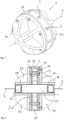
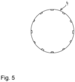
- An inspection device for examining pipelines in which a fluid, in particular water and/or oil, is transported, has a sensor carrier 1 which can be rolled through the pipeline during operation and which, in a section running transversely to an axis of rotation 2 (cf. Fig. 5 ) is provided with a circular circumference 4.
- Fig. 5 shows only the outer circumference in a sectional view without further functional parts of the inspection device.
- the inspection device or the sensor carrier 1 has several stabilizing means 6 arranged along the circumference 4, which in the present case are designed as permanent magnets arranged next to one another with a north pole N and a south pole S.
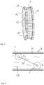
- the inspection device moves in a direction F ( Fig. 3 ), which corresponds to the longitudinal direction of the pipeline 8.
- the respective inspection device rolls along the inside of the pipeline 8.
- the magnets are spaced radially from the axis of rotation 2, causing the magnetic field to interact with the pipe wall 10, whereby the rolling on the inner surface of the pipe wall 10 and the associated magnetic field changes generate eddy currents that counteract an increase in the running speed of the inspection device in the direction F.
- the rolling of the inspection device in the pipe 8 is thus more uniform.
- the permanent magnets are aligned with their north/south orientation parallel to the axis of rotation 2.
- the magnets which are arranged close to one another along the circumference 4, are delimited on both sides by a circular ring-shaped enclosure 12 ( Fig. 2 ).
- These two enclosures 12 can also form the circumference and in particular form contact points with the pipe wall. In particular, however, they direct the magnetic field in the direction of the pipe wall 10 so that a stable interaction is created during operation.
- the enclosures 12, which in a further embodiment of the invention can also delimit the bar magnets in one piece and in a U-shape, are connected to one another or to a support structure 16 of the inspection device via fastening means 14.
- the support structure 16 is essentially formed with two mirror-image halves which have a plate-like base on which hollow-cylindrical sections 18 are arranged.
- An electronic unit 20 comprising a control unit and/or a data storage unit and/or an energy storage unit and/or an acceleration sensor and/or a communication unit is arranged in part of these halves and in a central cavity of the inspection device.
- the electronic unit can be sealed to the open ends of the hollow-cylindrical extension pieces.
- sensors 22 in the form of hydrophones are arranged in this end.
- the support structure of the sensor carrier 1 further comprises propulsion elements 24 in the form of lamellae, which are formed integrally with the hollow cylinder 18 and the plate-shaped base and which generate a flow resistance and ensure improved propulsion of the inspection device in the pipeline.
- An envelope of the device has an ellipsoidal shape, wherein the aforementioned ends with hydrophones and/or the area designed to rest on the pipeline wall can be additionally flattened in this as well as in other embodiments of the invention.
- the support structure 16 is made of a plastic, preferably of a polyurethane, and has damping properties in order to keep disturbances to the measurements caused by possible vibrations as low as possible.
- an annular, elastic damping element 26 Arranged around the magnets and forming the circumference is an annular, elastic damping element 26 made of plastic, which has a greater distance from the axis of rotation on its outer surface than the enclosures 12 representing rolling elements. During operation, the damping element 26 is compressed, whereby it counteracts the magnetic attraction forces and thus has a damping effect. In addition, the magnets are protected from mechanical damage and due to the increased surface friction, the device rolls better and more evenly, as the slip on the pipeline wall is reduced.
- coils 21 of a generator are shown in which an electrical voltage is induced when the device rolls, which is used to generate energy. This can charge the energy storage device or improve the power supply of the device.
- Cavities 27 present inside the device can be filled by means of a pump system (not shown in detail) in order to maintain the buoyancy of the inspection device in a medium 28 (cf. Fig. 4 ) in such a way that a respective inspection device can be used either as in Fig. 4 shown on the upper side of the pipe wall 10 or on the lower side of the pipe wall 10.
- the inspection devices shown can be connected to one another by an optional central unit 30 shown in dashed lines, for example in the form of a frame.
- a camera not referred to as a sensor for the purposes of this application in particular a 2D or 3D camera, can also be arranged in the inspection device, wherein an image capture is always generated in a specific relative position of the camera to the pipeline wall on the basis of the data of an acceleration sensor.
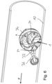
- FIG. 6 and 7 A further embodiment of the invention is shown in Fig. 6 and 7 provided with a support element 32 for supporting the inspection device on the pipe wall, in which the sensor carrier 1 is rotatably held.
- the sensor carrier 1 is held at one end by a part 34 of the support element 32, which in the above embodiment is in the form of a circular segment, and at the other end a roller wheel 36 is provided for support on the pipe wall.
- the part 34 serves to support the sensor carrier 1 by means of sliding or roller bearings.
- the axes of rotation of the roller wheel 36 and of the sensor carrier 1 run parallel and transversely to the longitudinal and travel direction of the pipe.
- the roller wheel 36 is the leading element of the inspection device, the sensor carrier 1 of which has propulsion elements 24 leading spirally away from a rotation axis.
- This sensor carrier 1 is also provided with a circular circumference 4, which is formed by surrounds 12. Magnets are arranged along the circumference as stabilizing means 6. Depending on the embodiment, the leading roller wheel 36 can also be provided with magnet
Landscapes
- Engineering & Computer Science (AREA)
- General Engineering & Computer Science (AREA)
- Multimedia (AREA)
- Signal Processing (AREA)
- Chemical & Material Sciences (AREA)
- Combustion & Propulsion (AREA)
- Mechanical Engineering (AREA)
- Investigating Or Analyzing Materials By The Use Of Magnetic Means (AREA)
- Investigating Or Analyzing Materials By The Use Of Ultrasonic Waves (AREA)
- Indicating And Signalling Devices For Elevators (AREA)
- Transplanting Machines (AREA)
Claims (17)
- Dispositif d'inspection destiné à l'examen de canalisations (8), comprenant un support de capteur (1) qui est apte à rouler à travers la canalisation (8) pendant le fonctionnement et qui est pourvu d'une circonférence (4) au moins sensiblement circulaire dans une vue en coupe transversale par rapport à un axe de rotation (2) et qui comporte au moins une unité de détection (3), le support de capteur (1) comprenant plusieurs moyens de stabilisation (6) disposés le long de la circonférence (4) et, pendant le fonctionnement, le dispositif d'inspection se déplaçant dans une direction au moins sensiblement transversale à l'axe de rotation et roulant sur la circonférence, caractérisé en ce que plusieurs aimants espacés radialement de l'axe de rotation (2) sont prévus comme moyens de stabilisation (6), le champ magnétique des aimants interagissant avec une paroi de canalisation (10) pendant le fonctionnement en vue d'une course plus stable.
- Dispositif d'inspection selon la revendication 1, caractérisé en ce qu'un ou plusieurs poids espacés radialement de l'axe de rotation (2) sont en plus prévus comme des moyens de stabilisation (6).
- Dispositif d'inspection selon la revendication 2, caractérisé en ce que l'orientation nord-sud des aimants conçus comme aimants permanents est parallèle à l'axe de rotation (2) .
- Dispositif d'inspection selon la revendication 2, caractérisé en ce que l'orientation nord-sud des aimants conçus comme aimants permanents s'étend radialement à l'axe de rotation (2).
- Dispositif d'inspection selon l'une des revendications précédentes 3 ou 4, caractérisé en ce que les aimants sont disposés les uns à côté des autres le long de la circonférence (4).
- Dispositif d'inspection selon l'une des revendications précédentes, caractérisé en ce que le ou les aimants sont limités au moins sur un côté par une bordure (12), notamment magnétisable, qui comporte un matériau magnétisable, qui est de préférence annulaire dans une vue en direction de l'axe de rotation (2) et qui forme notamment la circonférence (4).
- Dispositif d'inspection selon l'une des revendications précédentes, caractérisé en ce que le support de capteur (1) comporte une enveloppe de type sphérique ou ellipsoïde.
- Dispositif d'inspection selon la revendication 7, caractérisé en ce que dans l'enveloppe de type ellipsoïde les longueurs de deux demi-axes, notamment égales, sont supérieures à celles du troisième demi-axe situé dans l'axe de rotation.
- Dispositif d'inspection selon l'une des revendications précédentes 1 à 6, caractérisé en ce que le support de capteur (1) est maintenu de manière à pouvoir tourner dans un élément d'appui (32) prévu pour venir en appui sur la paroi de canalisation (10) afin de supporter le dispositif d'inspection, lequel élément d'appui comprend notamment le support de capteur (1) à une extrémité et est conçu pour venir en appui sur la paroi de canalisation (10) à l'autre extrémité.
- Dispositif d'inspection selon l'une des revendications précédentes, caractérisé en ce que la circonférence (4) est au moins formée par au moins un élément d'amortissement (26) de préférence annulaire et/ou élastique, réalisé au moins partiellement à partir d'une matière synthétique, et/ou par au moins un élément roulant.
- Dispositif d'inspection selon la revendication 10, caractérisé en ce qu'une structure porteuse (16) du support de capteur (1) est au moins formée à partir de la matière synthétique ou d'une autre.
- Dispositif d'inspection selon l'une des revendications précédentes, caractérisé en ce que l'unité de détection (3) du dispositif d'inspection comporte au moins un capteur d'un groupe comprenant des gyroscopes, des capteurs d'accélération, des capteurs de champ magnétique, des capteurs acoustiques, des capteurs EMAT, des capteurs de pression et des capteurs de température.
- Dispositif d'inspection selon l'une des revendications précédentes, caractérisé en ce que le dispositif d'inspection comporte une caméra et/ou un générateur pourvu d'une bobine génératrice.
- Dispositif d'inspection selon la revendication 12 et la revendication 13, caractérisé en ce que le dispositif d'inspection est conçu pour capturer une image et/ou une séquence d'images en fonction d'une position déterminée par un capteur.
- Dispositif d'inspection selon l'une des revendications précédentes, caractérisé en ce que le dispositif d'inspection comporte au moins un élément d'avancement (24) qui s'étend notamment depuis l'axe de rotation (2).
- Dispositif d'inspection selon l'une des revendications précédentes, caractérisé en ce que le support de capteur (1) a une densité moyenne modifiable par le biais de cavités (27) pouvant être remplies du dispositif d'inspection et/ou d'éléments pondéreux pouvant être intégrés dans le support de capteur (1) et/ou une structure porteuse remplaçable (16).
- Unité d'inspection selon l'une des revendications précédentes, caractérisée par une unité centrale (30) qui est reliée à un ou plusieurs dispositifs d'inspection selon l'une des revendications précédentes.
Applications Claiming Priority (2)
| Application Number | Priority Date | Filing Date | Title |
|---|---|---|---|
| DE102020102951.9A DE102020102951A1 (de) | 2020-02-05 | 2020-02-05 | Inspektionsvorrichtung und Inspektionseinheit |
| PCT/EP2021/052790 WO2021156433A1 (fr) | 2020-02-05 | 2021-02-05 | Dispositif d'inspection et unité d'inspection |
Publications (3)
| Publication Number | Publication Date |
|---|---|
| EP4100676A1 EP4100676A1 (fr) | 2022-12-14 |
| EP4100676B1 true EP4100676B1 (fr) | 2024-10-23 |
| EP4100676C0 EP4100676C0 (fr) | 2024-10-23 |
Family
ID=74732868
Family Applications (1)
| Application Number | Title | Priority Date | Filing Date |
|---|---|---|---|
| EP21707899.7A Active EP4100676B1 (fr) | 2020-02-05 | 2021-02-05 | Dispositif d'inspection et unité d'inspection |
Country Status (8)
| Country | Link |
|---|---|
| US (1) | US12331869B2 (fr) |
| EP (1) | EP4100676B1 (fr) |
| AU (1) | AU2021216117B2 (fr) |
| BR (1) | BR112022015452A2 (fr) |
| CA (1) | CA3167127A1 (fr) |
| DE (1) | DE102020102951A1 (fr) |
| MX (1) | MX2022009617A (fr) |
| WO (1) | WO2021156433A1 (fr) |
Families Citing this family (3)
| Publication number | Priority date | Publication date | Assignee | Title |
|---|---|---|---|---|
| BE1029385B1 (de) * | 2021-05-07 | 2022-12-05 | Rosen Swiss AG | Odometer sowie Inspektions- und/oder Reinigungsvorrichtung |
| US12498073B2 (en) | 2023-03-16 | 2025-12-16 | Saudi Arabian Oil Company | In-pipe localization of pipeline inspection gadgets |
| US12359562B2 (en) | 2023-08-14 | 2025-07-15 | Saudi Arabian Oil Company | Traceable and disintegrable artificial intelligence powered sensing system and method for the detection of defects in pipelines |
Family Cites Families (22)
| Publication number | Priority date | Publication date | Assignee | Title |
|---|---|---|---|---|
| US6820653B1 (en) * | 1999-04-12 | 2004-11-23 | Carnegie Mellon University | Pipe inspection and repair system |
| DE20020990U1 (de) | 2000-12-12 | 2001-04-05 | I.S.T. Industrie Service Technologie Beratungs- und Beteiligungsgesellschaft mbH, 22145 Hamburg | Rohrleitungsmolch |
| US7038444B2 (en) * | 2003-03-19 | 2006-05-02 | Southwest Research Institute | System and method for in-line stress measurement by continuous Barkhausen method |
| US7526944B2 (en) * | 2004-01-07 | 2009-05-05 | Ashok Sabata | Remote monitoring of pipelines using wireless sensor network |
| EA011497B1 (ru) | 2005-02-07 | 2009-04-28 | Пьюр Текнолоджиз Лтд. | Детектор аномалий для трубопроводов |
| CN101470237B (zh) * | 2007-12-25 | 2012-03-28 | 鸿富锦精密工业(深圳)有限公司 | 可旋转相机模组 |
| NZ590023A (en) * | 2008-06-25 | 2012-05-25 | Pure Technologies Ltd | Apparatus and method to locate an object within a pipeline using one fixed and one mobile ultrasonic acoustic transmitter and receiver |
| NO340894B1 (no) * | 2011-01-03 | 2017-07-10 | Empig As | En toveis rørledningsplugginnretning, fluidstrømbehandlingsanlegg og fremgangsmåte ved rensing |
| DE102011106523A1 (de) * | 2011-07-04 | 2013-01-10 | Giesecke & Devrient Gmbh | Prüfgerät und Verfahren zur Kalibrierung eines Prüfgeräts |
| US20140009598A1 (en) * | 2012-03-12 | 2014-01-09 | Siemens Corporation | Pipeline Inspection Piglets |
| US20140152803A1 (en) * | 2012-11-16 | 2014-06-05 | Northeast Gas Association | System, method & apparatus for remote pipe inspection |
| CN104106002B (zh) * | 2012-11-16 | 2017-10-13 | 松下电器(美国)知识产权公司 | 相机驱动装置 |
| DE102013011626A1 (de) | 2013-07-12 | 2015-01-15 | Rosen Swiss Ag | Molch, insbesondere Inspektions- oder Reinigungsmolch |
| KR102330848B1 (ko) * | 2013-11-30 | 2021-11-25 | 사우디 아라비안 오일 컴퍼니 | 자기 옴니-휠 |
| GB2540583B (en) * | 2015-07-22 | 2021-08-11 | I2I Pipelines Ltd | Improved pipe pig |
| CN105043312B (zh) * | 2015-08-27 | 2017-11-24 | 浙江省特种设备检验研究院 | 一种压力管道内检测用球形密布式探头超声测厚装置 |
| DE202016001778U1 (de) * | 2016-02-15 | 2016-07-18 | Memora Inc. | 360-Grad-Bildaufnahmevorrichtung, untergebracht in einem kugelförmigen Gehäuse |
| WO2018102112A1 (fr) * | 2016-11-29 | 2018-06-07 | Board Of Regents Of The Nevada System Of Higher Education, On Behalf Of The University Of Nevada, Reno | Robot grimpeur d'acier à roues magnétiques |
| EP3336509B1 (fr) | 2016-12-15 | 2020-07-29 | INGU Solutions Inc. | Dispositif de capteur et systèmes d'identification de fuites dans un conduit de fluide |
| US20180232874A1 (en) * | 2017-02-10 | 2018-08-16 | Ecosubsea As | Inspection vehicle |
| US10830837B2 (en) * | 2018-10-26 | 2020-11-10 | General Electric Company | Magnetic adhesive force monitoring system for magnetic wheeled robot |
| KR102687669B1 (ko) * | 2019-01-24 | 2024-07-24 | 삼성전자주식회사 | 구형 구조체를 포함하는 전자 장치 |
-
2020
- 2020-02-05 DE DE102020102951.9A patent/DE102020102951A1/de active Pending
-
2021
- 2021-02-05 BR BR112022015452A patent/BR112022015452A2/pt unknown
- 2021-02-05 CA CA3167127A patent/CA3167127A1/en active Pending
- 2021-02-05 US US17/760,247 patent/US12331869B2/en active Active
- 2021-02-05 WO PCT/EP2021/052790 patent/WO2021156433A1/fr not_active Ceased
- 2021-02-05 EP EP21707899.7A patent/EP4100676B1/fr active Active
- 2021-02-05 AU AU2021216117A patent/AU2021216117B2/en active Active
- 2021-02-05 MX MX2022009617A patent/MX2022009617A/es unknown
Also Published As
| Publication number | Publication date |
|---|---|
| US12331869B2 (en) | 2025-06-17 |
| CA3167127A1 (en) | 2021-08-12 |
| BR112022015452A2 (pt) | 2022-10-04 |
| WO2021156433A1 (fr) | 2021-08-12 |
| US20230054659A1 (en) | 2023-02-23 |
| EP4100676C0 (fr) | 2024-10-23 |
| DE102020102951A1 (de) | 2021-08-05 |
| MX2022009617A (es) | 2022-09-07 |
| EP4100676A1 (fr) | 2022-12-14 |
| AU2021216117A1 (en) | 2022-09-01 |
| AU2021216117B2 (en) | 2026-02-12 |
Similar Documents
| Publication | Publication Date | Title |
|---|---|---|
| EP4100676B1 (fr) | Dispositif d'inspection et unité d'inspection | |
| DE102007058043B4 (de) | Vorrichtung und Verfahren zur zerstörungsfreien Prüfung von Rohrleitungen | |
| DE69203671T2 (de) | Fahrzeug zur Verwendung in Rohren. | |
| EP0019313B1 (fr) | Palier rotatif magnétique | |
| DE69210911T2 (de) | Fahrzeug, durch Verwendung magnetischer Kräfte geeignet zur dreidimensionalen Fortbewegung | |
| EP2172593B1 (fr) | Procédé et dispositif pour l'inspection de haubans | |
| DE19900620A1 (de) | Rollenprüfstand für Kraftfahrzeuge | |
| EP0196020A2 (fr) | Véhicule pour tests électromagnétiques de parois de tubes en acier et procédé à cet effet | |
| JP2016531250A (ja) | 歯車装置用転がり軸受 | |
| EP2539723A1 (fr) | Procédé d'évaluation de décharges en arc et banc d'essai associé | |
| DE102012202522A1 (de) | Sensorlager | |
| DE2936304A1 (de) | Geraet zum zerstoerungsfreien pruefen | |
| DE10163430A1 (de) | In Rohren anwendbares magnetisches Defektoskop | |
| DE102010015061A1 (de) | Vorrichtung zur Lagerung und zum Antrieb eines rotierbaren Teils einer Gantry eines Computertomographiegerätes und Computertomographiegerät | |
| WO2012013443A2 (fr) | Agencement, procédé de fonctionnement et branchement pour un broyeur entraîné par un moteur annulaire | |
| DE102013000685B4 (de) | Mobiles Trägersystem für mindestens ein zur zerstörungsfreien Prüfung ausgebildetes Sensorelement | |
| WO2006050914A1 (fr) | Dispositif d'essai de matiere acoustique electromagnetique et/ou de mesure d'epaisseur sur un objet a tester presentant au moins une partie de matiere electroconductrice et ferromagnetique au moyen d'une roue de test | |
| DE3719492C2 (de) | Beulensuchmolch | |
| RU2539777C1 (ru) | Наружный сканирующий дефектоскоп | |
| WO2020151892A1 (fr) | Transporteur à courroie et tambour destiné à un transporteur à courroie | |
| JP6950961B2 (ja) | 水面下構造物用の電位測定治具及びこれを用いた電位測定方法並びに発生電流の検証方法 | |
| AT405335B (de) | Vorrichtung und verfahren zur bestimmung von fehlstellen einer rohrleitung für fluide | |
| WO2022234117A1 (fr) | Procédé et dispositif d'inspection pour l'examen de la protection cathodique d'une canalisation, plus particulièrement ferromagnétique | |
| WO2013107884A1 (fr) | Dispositif comportant au moins un élément roulant et procédé d'émission d'un signal | |
| DE2545370A1 (de) | Anordnung zum pruefen der querschweissnaehte eines grosskalibrigen stahlrohres |
Legal Events
| Date | Code | Title | Description |
|---|---|---|---|
| STAA | Information on the status of an ep patent application or granted ep patent |
Free format text: STATUS: UNKNOWN |
|
| STAA | Information on the status of an ep patent application or granted ep patent |
Free format text: STATUS: THE INTERNATIONAL PUBLICATION HAS BEEN MADE |
|
| PUAI | Public reference made under article 153(3) epc to a published international application that has entered the european phase |
Free format text: ORIGINAL CODE: 0009012 |
|
| STAA | Information on the status of an ep patent application or granted ep patent |
Free format text: STATUS: REQUEST FOR EXAMINATION WAS MADE |
|
| 17P | Request for examination filed |
Effective date: 20220824 |
|
| AK | Designated contracting states |
Kind code of ref document: A1 Designated state(s): AL AT BE BG CH CY CZ DE DK EE ES FI FR GB GR HR HU IE IS IT LI LT LU LV MC MK MT NL NO PL PT RO RS SE SI SK SM TR |
|
| DAV | Request for validation of the european patent (deleted) | ||
| DAX | Request for extension of the european patent (deleted) | ||
| RAP1 | Party data changed (applicant data changed or rights of an application transferred) |
Owner name: ROSEN IP AG |
|
| GRAP | Despatch of communication of intention to grant a patent |
Free format text: ORIGINAL CODE: EPIDOSNIGR1 |
|
| STAA | Information on the status of an ep patent application or granted ep patent |
Free format text: STATUS: GRANT OF PATENT IS INTENDED |
|
| INTG | Intention to grant announced |
Effective date: 20240523 |
|
| GRAS | Grant fee paid |
Free format text: ORIGINAL CODE: EPIDOSNIGR3 |
|
| GRAA | (expected) grant |
Free format text: ORIGINAL CODE: 0009210 |
|
| STAA | Information on the status of an ep patent application or granted ep patent |
Free format text: STATUS: THE PATENT HAS BEEN GRANTED |
|
| AK | Designated contracting states |
Kind code of ref document: B1 Designated state(s): AL AT BE BG CH CY CZ DE DK EE ES FI FR GB GR HR HU IE IS IT LI LT LU LV MC MK MT NL NO PL PT RO RS SE SI SK SM TR |
|
| REG | Reference to a national code |
Ref country code: GB Ref legal event code: FG4D Free format text: NOT ENGLISH |
|
| REG | Reference to a national code |
Ref country code: CH Ref legal event code: EP |
|
| REG | Reference to a national code |
Ref country code: DE Ref legal event code: R096 Ref document number: 502021005564 Country of ref document: DE |
|
| REG | Reference to a national code |
Ref country code: IE Ref legal event code: FG4D Free format text: LANGUAGE OF EP DOCUMENT: GERMAN |
|
| U01 | Request for unitary effect filed |
Effective date: 20241105 |
|
| U07 | Unitary effect registered |
Designated state(s): AT BE BG DE DK EE FI FR IT LT LU LV MT NL PT RO SE SI Effective date: 20241114 |
|
| U20 | Renewal fee for the european patent with unitary effect paid |
Year of fee payment: 5 Effective date: 20250224 |
|
| PG25 | Lapsed in a contracting state [announced via postgrant information from national office to epo] |
Ref country code: HR Free format text: LAPSE BECAUSE OF FAILURE TO SUBMIT A TRANSLATION OF THE DESCRIPTION OR TO PAY THE FEE WITHIN THE PRESCRIBED TIME-LIMIT Effective date: 20241023 Ref country code: IS Free format text: LAPSE BECAUSE OF FAILURE TO SUBMIT A TRANSLATION OF THE DESCRIPTION OR TO PAY THE FEE WITHIN THE PRESCRIBED TIME-LIMIT Effective date: 20250223 |
|
| PG25 | Lapsed in a contracting state [announced via postgrant information from national office to epo] |
Ref country code: ES Free format text: LAPSE BECAUSE OF FAILURE TO SUBMIT A TRANSLATION OF THE DESCRIPTION OR TO PAY THE FEE WITHIN THE PRESCRIBED TIME-LIMIT Effective date: 20241023 |
|
| PGFP | Annual fee paid to national office [announced via postgrant information from national office to epo] |
Ref country code: NO Payment date: 20250218 Year of fee payment: 5 |
|
| PG25 | Lapsed in a contracting state [announced via postgrant information from national office to epo] |
Ref country code: GR Free format text: LAPSE BECAUSE OF FAILURE TO SUBMIT A TRANSLATION OF THE DESCRIPTION OR TO PAY THE FEE WITHIN THE PRESCRIBED TIME-LIMIT Effective date: 20250124 |
|
| PG25 | Lapsed in a contracting state [announced via postgrant information from national office to epo] |
Ref country code: PL Free format text: LAPSE BECAUSE OF FAILURE TO SUBMIT A TRANSLATION OF THE DESCRIPTION OR TO PAY THE FEE WITHIN THE PRESCRIBED TIME-LIMIT Effective date: 20241023 |
|
| PGFP | Annual fee paid to national office [announced via postgrant information from national office to epo] |
Ref country code: GB Payment date: 20250220 Year of fee payment: 5 |
|
| PG25 | Lapsed in a contracting state [announced via postgrant information from national office to epo] |
Ref country code: RS Free format text: LAPSE BECAUSE OF FAILURE TO SUBMIT A TRANSLATION OF THE DESCRIPTION OR TO PAY THE FEE WITHIN THE PRESCRIBED TIME-LIMIT Effective date: 20250123 |
|
| PG25 | Lapsed in a contracting state [announced via postgrant information from national office to epo] |
Ref country code: SM Free format text: LAPSE BECAUSE OF FAILURE TO SUBMIT A TRANSLATION OF THE DESCRIPTION OR TO PAY THE FEE WITHIN THE PRESCRIBED TIME-LIMIT Effective date: 20241023 |
|
| PG25 | Lapsed in a contracting state [announced via postgrant information from national office to epo] |
Ref country code: SK Free format text: LAPSE BECAUSE OF FAILURE TO SUBMIT A TRANSLATION OF THE DESCRIPTION OR TO PAY THE FEE WITHIN THE PRESCRIBED TIME-LIMIT Effective date: 20241023 |
|
| PG25 | Lapsed in a contracting state [announced via postgrant information from national office to epo] |
Ref country code: CZ Free format text: LAPSE BECAUSE OF FAILURE TO SUBMIT A TRANSLATION OF THE DESCRIPTION OR TO PAY THE FEE WITHIN THE PRESCRIBED TIME-LIMIT Effective date: 20241023 |
|
| PLBE | No opposition filed within time limit |
Free format text: ORIGINAL CODE: 0009261 |
|
| STAA | Information on the status of an ep patent application or granted ep patent |
Free format text: STATUS: NO OPPOSITION FILED WITHIN TIME LIMIT |
|
| PG25 | Lapsed in a contracting state [announced via postgrant information from national office to epo] |
Ref country code: MC Free format text: LAPSE BECAUSE OF FAILURE TO SUBMIT A TRANSLATION OF THE DESCRIPTION OR TO PAY THE FEE WITHIN THE PRESCRIBED TIME-LIMIT Effective date: 20241023 |
|
| REG | Reference to a national code |
Ref country code: CH Ref legal event code: PL |
|
| 26N | No opposition filed |
Effective date: 20250724 |
|
| PG25 | Lapsed in a contracting state [announced via postgrant information from national office to epo] |
Ref country code: CH Free format text: LAPSE BECAUSE OF NON-PAYMENT OF DUE FEES Effective date: 20250228 |
|
| PG25 | Lapsed in a contracting state [announced via postgrant information from national office to epo] |
Ref country code: IE Free format text: LAPSE BECAUSE OF NON-PAYMENT OF DUE FEES Effective date: 20250205 |