EP4100676B1 - Inspection device and inspection unit - Google Patents
Inspection device and inspection unit Download PDFInfo
- Publication number
- EP4100676B1 EP4100676B1 EP21707899.7A EP21707899A EP4100676B1 EP 4100676 B1 EP4100676 B1 EP 4100676B1 EP 21707899 A EP21707899 A EP 21707899A EP 4100676 B1 EP4100676 B1 EP 4100676B1
- Authority
- EP
- European Patent Office
- Prior art keywords
- inspection device
- axis
- rotation
- circumference
- magnets
- Prior art date
- Legal status (The legal status is an assumption and is not a legal conclusion. Google has not performed a legal analysis and makes no representation as to the accuracy of the status listed.)
- Active
Links
Images

Classifications
-
- F—MECHANICAL ENGINEERING; LIGHTING; HEATING; WEAPONS; BLASTING
- F16—ENGINEERING ELEMENTS AND UNITS; GENERAL MEASURES FOR PRODUCING AND MAINTAINING EFFECTIVE FUNCTIONING OF MACHINES OR INSTALLATIONS; THERMAL INSULATION IN GENERAL
- F16L—PIPES; JOINTS OR FITTINGS FOR PIPES; SUPPORTS FOR PIPES, CABLES OR PROTECTIVE TUBING; MEANS FOR THERMAL INSULATION IN GENERAL
- F16L55/00—Devices or appurtenances for use in, or in connection with, pipes or pipe systems
- F16L55/26—Pigs or moles, i.e. devices movable in a pipe or conduit with or without self-contained propulsion means
- F16L55/28—Constructional aspects
-
- F—MECHANICAL ENGINEERING; LIGHTING; HEATING; WEAPONS; BLASTING
- F16—ENGINEERING ELEMENTS AND UNITS; GENERAL MEASURES FOR PRODUCING AND MAINTAINING EFFECTIVE FUNCTIONING OF MACHINES OR INSTALLATIONS; THERMAL INSULATION IN GENERAL
- F16L—PIPES; JOINTS OR FITTINGS FOR PIPES; SUPPORTS FOR PIPES, CABLES OR PROTECTIVE TUBING; MEANS FOR THERMAL INSULATION IN GENERAL
- F16L55/00—Devices or appurtenances for use in, or in connection with, pipes or pipe systems
- F16L55/26—Pigs or moles, i.e. devices movable in a pipe or conduit with or without self-contained propulsion means
-
- H—ELECTRICITY
- H04—ELECTRIC COMMUNICATION TECHNIQUE
- H04N—PICTORIAL COMMUNICATION, e.g. TELEVISION
- H04N23/00—Cameras or camera modules comprising electronic image sensors; Control thereof
- H04N23/60—Control of cameras or camera modules
-
- H—ELECTRICITY
- H04—ELECTRIC COMMUNICATION TECHNIQUE
- H04N—PICTORIAL COMMUNICATION, e.g. TELEVISION
- H04N5/00—Details of television systems
- H04N5/76—Television signal recording
-
- H—ELECTRICITY
- H04—ELECTRIC COMMUNICATION TECHNIQUE
- H04N—PICTORIAL COMMUNICATION, e.g. TELEVISION
- H04N7/00—Television systems
- H04N7/18—Closed-circuit television [CCTV] systems, i.e. systems in which the video signal is not broadcast
- H04N7/188—Capturing isolated or intermittent images triggered by the occurrence of a predetermined event, e.g. an object reaching a predetermined position
-
- F—MECHANICAL ENGINEERING; LIGHTING; HEATING; WEAPONS; BLASTING
- F16—ENGINEERING ELEMENTS AND UNITS; GENERAL MEASURES FOR PRODUCING AND MAINTAINING EFFECTIVE FUNCTIONING OF MACHINES OR INSTALLATIONS; THERMAL INSULATION IN GENERAL
- F16L—PIPES; JOINTS OR FITTINGS FOR PIPES; SUPPORTS FOR PIPES, CABLES OR PROTECTIVE TUBING; MEANS FOR THERMAL INSULATION IN GENERAL
- F16L2101/00—Uses or applications of pigs or moles
- F16L2101/30—Inspecting, measuring or testing
Definitions
- the present invention relates to an inspection device for examining pipelines, comprising a sensor carrier which can be rolled through the pipeline during operation, which is provided with an at least substantially circular circumference in a section running transversely to an axis of rotation and which has at least one sensor unit.
- Such spherical inspection devices move irregularly in the pipeline due to the dynamics of the transported medium and the pipeline path; they can jump, rotate or slide around all three spatial axes. These irregular movements result in a very high level of effort in data interpretation, to the point of making it impossible due to low signal-to-noise ratios. This applies both to the interpretation of the defect data and the position of the defects.
- Such a state of the art can be found, for example, in the EP 2902690 B1 or the US 2008204008 A1 described.
- CN 105043312 discloses an inspection device having a plurality of ultrasonic sensors distributed over the outer surface of the ball-shaped inspection device.
- the EP 1 215 436 A2 discloses a pipeline pig with an annular magnet holder designed with an oversize relative to a pipeline to be pigged.
- the sensor carrier comprises a plurality of stabilizing means arranged along the circumference, wherein a plurality of magnets radially spaced from the axis of rotation are provided as stabilizing means, wherein a respective magnetic field of the magnets interacts with the pipeline wall during operation for a more stable run.
- the stabilizing means or means promote or improve a movement of the inspection device in a direction at least substantially transverse to a selected axis of rotation and a rolling on the circumference during operation.
- the rolling takes place in particular along the pipeline axis during operation, wherein the axis of rotation is preferably at least substantially transverse to it when it forms an angle of +/- 10° with the pipeline axis.
- An improvement in the rolling behavior is particularly present when the rolling of the inspection device around a circumference in the pipeline around the selected axis of rotation can be carried out better, ie more evenly or at all, than around another circumference with a further axis of rotation lying transversely or at an angle to the selected axis of rotation.
- the rolling of the device takes place in particular on the part or parts of the inspection device that form the circumference.
- the stabilizing means or means are in particular arranged away from the axis of rotation, i.e. in or on the outer circumference, possibly forming the outer circumference and, through the force they emit or the impulse they generate, ensuring a more stable rolling of the inspection device.
- the stabilizing means(s) arranged along the circumference promote movement when, for example, maintaining an orientation of a rotation axis of the device is stabilized, for example by increasing a generated angular momentum or by means for adhering to the pipeline wall.
- the latter means support a gravity-induced movement of the inspection device in the pipeline along the 0 o'clock or 6 o'clock position.
- a circular circumference is given when the inspection device can roll on a flat plane on the circular circumference without acceleration peaks interfering with the measurement.
- a circular circumference is therefore a circumference that is exactly circular or, for example, approximately circular due to a polygon.
- An ellipsoidal shape is a shape that deviates from an ellipsoid either by exactly one ellipsoid or by a few cm, ie less than 10 cm, preferably less than 5 cm.
- the stabilizing means can form the circumference or be arranged close to the circumference; for example, the cut running transversely to the axis of rotation can run through the stabilizing means, which are in particular spaced radially from the axis of rotation, or run along them.
- one or more weights radially spaced from the axis of rotation and several magnets radially spaced from the axis of rotation are provided as stabilizing means, wherein a respective magnetic field of the magnet(s) interacts with the pipeline wall during operation.
- the magnets have a higher weight than areas of the inspection device that are radially offset from the axis of rotation. While a weight already increases the generated angular momentum and thus promotes compliance with the direction of the axis of rotation, one or more magnets in the circumference or along the circumference of the inspection device not only increase the angular momentum but also at least increase the adhesion between the wall and the device and thus greatly promote slip-free running.
- the magnetizable material of the pipeline is magnetized and demagnetized again when the magnet is removed during rolling, which creates eddy currents that counteract an increase in the running speed of the device and thus greatly improve the running behavior.
- the magnets which themselves can also represent additional weights along the circumference, thus promote a more stable running of the device on the one hand due to gravity and on the other hand due to the magnetic interaction.
- Permanent magnets are preferably used as magnets. However, electromagnets can also be used, so that the strength of the interaction with the wall of the pipeline can be adjusted by an appropriate control device.
- the north-south alignment of the permanent magnets preferably runs parallel to the axis of rotation, so that no forces occur on the circumference in the tangential direction of the circumference.
- one or more or even all of the magnets designed as permanent magnets can be aligned radially to the axis of rotation with their north-south alignment, so that no tangential forces arise.
- This rotationally symmetrical arrangement of the magnets in the stationary state does not generate any tangential forces, it allows for easier rolling and only when the device rolls do magnetic forces build up due to the eddy currents induced in the pipe, which counteract the movement and slow down the device's propulsion.
- a braking force can therefore be set using a corresponding control device, for example depending on the speed to be achieved or specified or on the basis of a speed range, particularly when using electromagnets.
- the magnets are arranged close to one another or next to one another along the circumference, with a close arrangement being defined as a distance between the magnets, with or without a possible border, in particular ⁇ 5 cm, preferably ⁇ 3 cm.
- the magnets lie directly next to each other with or without a frame.
- the magnet or magnets are delimited on at least one side by a frame comprising a magnetizable material and preferably made of this material.
- this frame is preferably circular and magnetizable.
- this frame can also form the circumference. This allows the magnetic field lines to be concentrated in the direction of the wall, so that the magnetic flux is better guided into the pipe wall.
- two metal disks in the shape of a circular ring can be used on the sides of the magnets built into the circumference of the device.
- the sensor carrier is preferably designed to be spherical or elliptic at least with respect to one envelope.
- the lengths of two semi-axes are preferably greater than the length of the third semi-axis lying in the axis of rotation.
- the third semi-axis should preferably be between half and 100% of the length of one of the other two semi-axes. This effectively prevents tipping over, so that this shape achieves improved passageability.
- the device can be adapted to the curvature of the pipeline with respect to its envelope. This makes alignment along the pipe axis easier due to the flow of the medium and at the same time creates space for any drive elements.
- an ellipsoidal shape is a rotationally symmetrical shape that can roll stably through a pipeline and in which the length of the third semi-axis is not so short that the device quickly tips over onto its side.
- the stabilizing means which are designed in particular as magnets, alone and in particular in combination with the shape of the inspection device make the latter self-stabilizing and thus right itself when moving along the pipeline if the inspection device has tipped over onto its side.
- the sensor carrier which is otherwise also provided with a spherical or at least essentially ellipsoidal envelope, can be held and in particular mounted in a support element provided for supporting the inspection device on the pipeline wall, in particular which comprises the sensor carrier at one end and is designed at the other end for support on the pipeline wall, preferably with a roller wheel that is smaller in circumference than the sensor carrier circumference.
- the axis of rotation of such a roller wheel and that of the sensor carrier are preferably designed parallel. This results in a particularly stable travel through the pipeline at its 6 o'clock position, with the roller wheel, which is made in particular of polyurethane, preferably being the front wheel in the direction of travel.
- a sensor, an energy storage device and/or electronics can additionally be arranged in an elongated carrier connecting the two ends of the support element.
- the circumference is at least partly formed by at least one damping element made at least partially from plastic, preferably in the form of a ring or at least a ring segment and/or elastic.
- the damping element can have recesses for sensor units. Due to an appropriate choice of material with a plastic that has a sufficiently high coefficient of friction for the pipeline, the adhesion to the pipeline wall is increased and slip-free running is promoted.
- the damping element can ensure vibration-free running if there are impurities or elevations on the inside of the surface in the form of weld seams or the like.
- the ring-segment-shaped damping element can form a bearing for the sensor carrier as part of the support element.
- the sensor carrier then rotates in the damping element, which then only dampens to a small extent but rather serves as a bearing.
- the damping properties of the ring-segment-shaped damping element can be largely dispensed with, whereby the support element with the ring-segment-shaped part then only forms a holder or a bearing for the sensor carrier.
- the inspection device has one or more rolling elements that form defined contact areas of the inspection device for contact with the pipeline wall, preferably to the left and right of the magnets, so that the device is further stabilized and rolling is possible in a more defined manner.
- the rolling elements are the parts of the magnet enclosures that are radially outer to the axis of rotation.
- the height of the damping element(s) above adjacent parts of the inspection device may preferably correspond approximately to the height of a standard weld seam of the pipeline above its other internal surface and may be between 0.1 cm and 3 cm.
- the entire sensor carrier has damping properties that benefit data acquisition by any sensors of sensor units. Any vibrations and the energy introduced into the device by these can be dissipated better.
- the inspection device has at least one sensor from a group comprising gyroscopes, acceleration sensors, magnetic field sensors, sound sensors, E-MAT sensors, pressure sensors and temperature sensors.
- the rotation of the device can be used to perform odometric measurements.
- the distance travelled can be determined by the angle of rotation and the diameter of the device.
- the angle of rotation can be measured, for example, by measuring the direction of gravity with a gyroscope and/or an accelerometer and/or by detecting the contact of at least one point of the device with the wall.
- the centrifugal acceleration measurable with the gyroscope or the accelerometer can also be used to calculate the speed of the device and then also estimate the path of the device.
- acceleration peaks that can be measured with the acceleration sensor can be used to detect welds. Since the position of the welds is often known, these signals can be used to correct or determine the position of the device.
- a Hall sensor can be used as a magnetic field sensor according to a further development of the invention.
- touching the wall in particular in the area where the magnets are closest to the Wall changes the magnetic field significantly, which can be detected with the Hall sensor that rolls past the position with the device.
- From the signal curve recorded here not only the exact point of contact but also a corresponding contact time can be recorded.
- the rotation of the device can be calculated on the basis of the recorded events, whereby the time is recorded in appropriate electronics either in the control unit or in the sensor itself and the rotation of the device can then be calculated on the basis of the recorded signals in the inspection device itself or later.
- At least one coil can be integrated into an inventive device.
- a magnetic field detected in the coil can then also be used to calculate the rotation of the device.
- Sound sensors in the form of a hydrophone can be used to transmit information to the device or to emit sound into the pipe wall for the purpose of locating the device or transmitting information in another way. This information can then also be received from outside the pipe wall or with sound sensors or microphones integrated into the pipe wall. Sound sensors can also be ultrasonic sensors used to carry out integrity tests.
- the device according to the invention can also have EMAT sensors, ie electromagnetic transducers that transmit sound without liquid coupling media via electromagnetic Interactions in the pipe wall can generate ultrasound.
- the magnets installed as stabilizing agents can be used to create a magnetic field necessary for generating the ultrasound.
- the EMAT sensors are then preferably arranged offset from the magnets in different directions in the direction of the axis of rotation of the inspection device.
- Pressure and temperature sensors can be used to correct the data obtained.
- the inspection device can have at least one camera.
- the position of the camera can advantageously be determined using an acceleration sensor of the inspection device, whereby images can be recorded at predefined positions of the camera.
- the camera can record image sequences, i.e. videos.
- the inspection device also has one or more cameras with the main viewing direction along the axis of rotation.
- a continuous view of the inside of the pipe can be created automatically.
- video recordings can be created for a specific camera position, as if the camera were not rotated with the device.
- the recording time is tied to the position of the device, this results in the pipe wall being covered evenly with the images, regardless of the the running speed of the device.
- the recording of images or videos at a specific position can be initiated automatically or triggered by an external signal.
- the position of the device can be linked to the start of a series of measurements in which, for example, one or more ultrasonic sensors start a measurement.
- the data set stored in the device can then be evaluated for a specific sensor position.
- a data set can also be evaluated during the run using appropriate transmission means via the pipeline or, in some variants, by cable.
- Lighting means particularly in the form of LEDs, are preferably assigned to each respective camera.
- the inspection device advantageously comprises a generator with a generator coil that is wound with several turns so that the magnetic flux through the individual turns changes constantly as the device rotates. This induces an electrical voltage that is used to charge any batteries that may be present and to power the electronics.
- the inspection device is designed to record an image and/or a sequence of images depending on a position determined by a sensor.
- the inspection device is provided with at least one propulsion element that extends away from the axis of rotation.
- This can be, for example, slats or webs arranged to the left and right of the stabilizing means in relation to the axis of rotation, the construction being designed in particular so that the same load-bearing capacity is achieved when the device is rotated by 180° around the axis of rotation. This ensures that the device can continue to run without restriction in the event of an unexpected 180° rotation.
- the slats are designed in such a way that a downstream torque is generated around the axis of rotation. This can be achieved, for example, by appropriately coiled slats.
- a device according to the invention is designed in a further embodiment such that the sensor carrier has a variable average density through fillable cavities of the inspection device and/or weight elements that can be integrated into the sensor carrier and/or an exchangeable support structure. This allows a zero or six o'clock position of the inspection device to be set for a pipeline with a liquid medium.
- the latter can be widened by side stabilizers, for example in the form of protruding arms or rudders.
- a central unit for example in the form of a frame, connects several inspection devices as described above or below.
- Such a central unit can have further functional units, for example an energy storage device and/or a data storage device.
- the device can also be used as an odometer and/or as a measuring unit of a conventional pig.
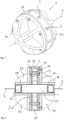
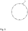
- An inspection device for examining pipelines in which a fluid, in particular water and/or oil, is transported, has a sensor carrier 1 which can be rolled through the pipeline during operation and which, in a section running transversely to an axis of rotation 2 (cf. Fig. 5 ) is provided with a circular circumference 4.
- Fig. 5 shows only the outer circumference in a sectional view without further functional parts of the inspection device.
- the inspection device or the sensor carrier 1 has several stabilizing means 6 arranged along the circumference 4, which in the present case are designed as permanent magnets arranged next to one another with a north pole N and a south pole S.
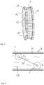
- the inspection device moves in a direction F ( Fig. 3 ), which corresponds to the longitudinal direction of the pipeline 8.
- the respective inspection device rolls along the inside of the pipeline 8.
- the magnets are spaced radially from the axis of rotation 2, causing the magnetic field to interact with the pipe wall 10, whereby the rolling on the inner surface of the pipe wall 10 and the associated magnetic field changes generate eddy currents that counteract an increase in the running speed of the inspection device in the direction F.
- the rolling of the inspection device in the pipe 8 is thus more uniform.
- the permanent magnets are aligned with their north/south orientation parallel to the axis of rotation 2.
- the magnets which are arranged close to one another along the circumference 4, are delimited on both sides by a circular ring-shaped enclosure 12 ( Fig. 2 ).
- These two enclosures 12 can also form the circumference and in particular form contact points with the pipe wall. In particular, however, they direct the magnetic field in the direction of the pipe wall 10 so that a stable interaction is created during operation.
- the enclosures 12, which in a further embodiment of the invention can also delimit the bar magnets in one piece and in a U-shape, are connected to one another or to a support structure 16 of the inspection device via fastening means 14.
- the support structure 16 is essentially formed with two mirror-image halves which have a plate-like base on which hollow-cylindrical sections 18 are arranged.
- An electronic unit 20 comprising a control unit and/or a data storage unit and/or an energy storage unit and/or an acceleration sensor and/or a communication unit is arranged in part of these halves and in a central cavity of the inspection device.
- the electronic unit can be sealed to the open ends of the hollow-cylindrical extension pieces.
- sensors 22 in the form of hydrophones are arranged in this end.
- the support structure of the sensor carrier 1 further comprises propulsion elements 24 in the form of lamellae, which are formed integrally with the hollow cylinder 18 and the plate-shaped base and which generate a flow resistance and ensure improved propulsion of the inspection device in the pipeline.
- An envelope of the device has an ellipsoidal shape, wherein the aforementioned ends with hydrophones and/or the area designed to rest on the pipeline wall can be additionally flattened in this as well as in other embodiments of the invention.
- the support structure 16 is made of a plastic, preferably of a polyurethane, and has damping properties in order to keep disturbances to the measurements caused by possible vibrations as low as possible.
- an annular, elastic damping element 26 Arranged around the magnets and forming the circumference is an annular, elastic damping element 26 made of plastic, which has a greater distance from the axis of rotation on its outer surface than the enclosures 12 representing rolling elements. During operation, the damping element 26 is compressed, whereby it counteracts the magnetic attraction forces and thus has a damping effect. In addition, the magnets are protected from mechanical damage and due to the increased surface friction, the device rolls better and more evenly, as the slip on the pipeline wall is reduced.
- coils 21 of a generator are shown in which an electrical voltage is induced when the device rolls, which is used to generate energy. This can charge the energy storage device or improve the power supply of the device.
- Cavities 27 present inside the device can be filled by means of a pump system (not shown in detail) in order to maintain the buoyancy of the inspection device in a medium 28 (cf. Fig. 4 ) in such a way that a respective inspection device can be used either as in Fig. 4 shown on the upper side of the pipe wall 10 or on the lower side of the pipe wall 10.
- the inspection devices shown can be connected to one another by an optional central unit 30 shown in dashed lines, for example in the form of a frame.
- a camera not referred to as a sensor for the purposes of this application in particular a 2D or 3D camera, can also be arranged in the inspection device, wherein an image capture is always generated in a specific relative position of the camera to the pipeline wall on the basis of the data of an acceleration sensor.
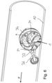
- FIG. 6 and 7 A further embodiment of the invention is shown in Fig. 6 and 7 provided with a support element 32 for supporting the inspection device on the pipe wall, in which the sensor carrier 1 is rotatably held.
- the sensor carrier 1 is held at one end by a part 34 of the support element 32, which in the above embodiment is in the form of a circular segment, and at the other end a roller wheel 36 is provided for support on the pipe wall.
- the part 34 serves to support the sensor carrier 1 by means of sliding or roller bearings.
- the axes of rotation of the roller wheel 36 and of the sensor carrier 1 run parallel and transversely to the longitudinal and travel direction of the pipe.
- the roller wheel 36 is the leading element of the inspection device, the sensor carrier 1 of which has propulsion elements 24 leading spirally away from a rotation axis.
- This sensor carrier 1 is also provided with a circular circumference 4, which is formed by surrounds 12. Magnets are arranged along the circumference as stabilizing means 6. Depending on the embodiment, the leading roller wheel 36 can also be provided with magnet
Landscapes
- Engineering & Computer Science (AREA)
- General Engineering & Computer Science (AREA)
- Multimedia (AREA)
- Signal Processing (AREA)
- Chemical & Material Sciences (AREA)
- Combustion & Propulsion (AREA)
- Mechanical Engineering (AREA)
- Investigating Or Analyzing Materials By The Use Of Magnetic Means (AREA)
- Investigating Or Analyzing Materials By The Use Of Ultrasonic Waves (AREA)
- Indicating And Signalling Devices For Elevators (AREA)
- Transplanting Machines (AREA)
Description
Die vorliegende Erfindung betrifft eine Inspektionsvorrichtung zur Untersuchung von Rohrleitungen, umfassend einen im Betriebsfall durch die Rohrleitung rollbaren Sensorträger, der in einem quer zu einer Drehachse verlaufenden Schnitt mit einem zumindest im Wesentlichen kreisartigen Umfang versehen ist und der zumindest eine Sensoreinheit aufweist.The present invention relates to an inspection device for examining pipelines, comprising a sensor carrier which can be rolled through the pipeline during operation, which is provided with an at least substantially circular circumference in a section running transversely to an axis of rotation and which has at least one sensor unit.
In Rohrleitungen, insbesondere in Form von magnetisierbaren Stahlrohren, werden weltweit Medien wie Öl, Gas, Wasser oder Gemische hiervon transportiert. Im Laufe der Lebensdauer einer solchen Rohrleitung können in deren Wand verschiedene Defekte auftreten. Hierzu zählen Verschleiß- und Ermüdungserscheinungen, die zu langfristigen Betriebsstörungen führen können. Mit zunehmendem Alter einer Rohrleitung treten diese Defekte naturgemäß zunehmend auf, weswegen Rohrleitungen verstärkt überwacht werden müssen.Media such as oil, gas, water or mixtures thereof are transported worldwide in pipelines, particularly in the form of magnetizable steel pipes. Over the course of the service life of such a pipeline, various defects can occur in its wall. These include signs of wear and fatigue, which can lead to long-term operational disruptions. As a pipeline ages, these defects naturally become more common, which is why pipelines need to be monitored more closely.
Die gebräuchlichste Methode der Inspektion von Rohrleitungen ist die Inspektion mit sogenannten intelligenten Molchen, was allerdings beispielsweise in Abhängigkeit von der Geometrie und dem Verlauf der Rohrleitung nicht immer möglich ist. Daher werden als Ersatz für intelligente Molche Vorrichtungen in Form einer Kugel verwendet. Eine solche, kompakte Konstruktion weist eine höhere Rohrleitungsgängigkeit und entsprechend sehr gute Passageeigenschaften auf.The most common method of inspecting pipelines is inspection using so-called intelligent pigs, although this is not always possible depending on the geometry and route of the pipeline. Therefore, devices in the shape of a ball are used as a replacement for intelligent pigs. Such a compact design has a higher degree of pipeline mobility and correspondingly very good passage properties.
Solche kugelförmigen Inspektionsvorrichtungen bewegen sich in der Rohrleitung aufgrund der Dynamik des transportierten Mediums und des Rohrleitungsverlaufs unregelmäßig, sie können um alle drei Raumachsen springen, drehen oder gleiten. Aus diesen unregelmäßigen Bewegungen ergibt sich ein sehr hoher Aufwand bei der Dateninterpretation bis hin zu deren Unmöglichkeit aufgrund zu niedriger Signalzu-Rausch-Verhältnissen. Dies gilt sowohl für die Interpretation der Defektdaten als auch der Position der Defekte. Ein solcher Stand der Technik ist beispielsweise in der
In der
In der
Die
Es ist Aufgabe der vorliegenden Erfindung, eine Inspektionsvorrichtung mit einem stabileren Laufverhalten zu schaffen.It is an object of the present invention to provide an inspection device with a more stable running behavior.
Die Aufgabe wird gelöst durch einen Gegenstand gemäß Anspruch 1 sowie durch einen Gegenstand gemäß Anspruch 16. Vorteilhafte Ausgestaltungen sind den Unteransprüchen sowie der nachfolgenden Beschreibung zu entnehmen.The object is achieved by an object according to
Erfindungsgemäß ist vorgesehen, dass der Sensorträger mehrere entlang des Umfangs angeordnete Stabilisierungsmittel umfasst, wobei als Stabilisierungsmittel mehrere von der Drehachse radial beabstandete Magnete vorgesehen sind, wobei ein jeweiliges Magnetfeld der Magnete im Betriebsfall für einen stabileren Lauf mit der Rohrleitungswand wechselwirkt. Das oder die Stabilisierungsmittel begünstigen oder verbessern im Betriebsfall eine Bewegung der Inspektionsvorrichtung in eine Richtung zumindest im Wesentlichen quer zu einer gewählten Drehachse und ein Abrollen auf dem Umfang. Das Abrollen erfolgt im Betriebsinsbesondere insbesondere entlang der Rohrleitungsachse, wobei die Drehachse vorzugsweise dann zumindest im Wesentlichen quer dazu steht, wenn sie mit der Rohrleitungsachse einen Winkel von +/- 10° einnimmt.According to the invention, the sensor carrier comprises a plurality of stabilizing means arranged along the circumference, wherein a plurality of magnets radially spaced from the axis of rotation are provided as stabilizing means, wherein a respective magnetic field of the magnets interacts with the pipeline wall during operation for a more stable run. The stabilizing means or means promote or improve a movement of the inspection device in a direction at least substantially transverse to a selected axis of rotation and a rolling on the circumference during operation. The rolling takes place in particular along the pipeline axis during operation, wherein the axis of rotation is preferably at least substantially transverse to it when it forms an angle of +/- 10° with the pipeline axis.
Eine Verbesserung des Abrollverhaltens liegt insbesondere dann vor, wenn das Abrollen der Inspektionsvorrichtung um einen Umfang in der Rohrleitung um die gewählte Drehachse besser, d.h. gleichmäßiger oder überhaupt als um einen anderen Umfang mit einer dann quer oder angewinkelt zu der gewählten Drehachse liegenden weiteren Drehachse erfolgen kann. Das Abrollen der Vorrichtung erfolgt insbesondere auf dem oder den den Umfang ausbildenden Teilen der Inspektionsvorrichtung.An improvement in the rolling behavior is particularly present when the rolling of the inspection device around a circumference in the pipeline around the selected axis of rotation can be carried out better, ie more evenly or at all, than around another circumference with a further axis of rotation lying transversely or at an angle to the selected axis of rotation. The rolling of the device takes place in particular on the part or parts of the inspection device that form the circumference.
Das oder die Stabilisierungsmittel sind insbesondere entfernt von der Drehachse, d.h., im oder am äußeren Umfang angeordnet, bilden diesen gegebenenfalls mit aus und sorgen durch die von ihnen ausgehende Kraft oder einen hierdurch entstehenden Impuls für einen stabileres Abrollen der Inspektionsvorrichtung.The stabilizing means or means are in particular arranged away from the axis of rotation, i.e. in or on the outer circumference, possibly forming the outer circumference and, through the force they emit or the impulse they generate, ensuring a more stable rolling of the inspection device.
Unabhängig davon, ob es sich bei dem Sensorträger um einen im Wesentlichen kreisartigen oder ellipsoidartigen Sensorträger handelt wird, wird durch das oder die Stabilisierungsmittel, die entlang des Umfangs angeordnet sind, eine Bewegung dann begünstigt, wenn beispielsweise die Einhaltung einer Ausrichtung einer Drehachse der Vorrichtung stabilisiert wird, beispielsweise durch Erhöhung eines erzeugten Drehimpulses oder durch Mittel zum Anhaften an der Rohrleitungswand. Durch letztere Mittel wird eine schwerkraftbedingte Bewegung der Inspektionsvorrichtung in der Rohrleitung entlang der 0-Uhr- oder der 6-Uhr-Position unterstützt.Regardless of whether the sensor carrier is a substantially circular or ellipsoidal sensor carrier, the stabilizing means(s) arranged along the circumference promote movement when, for example, maintaining an orientation of a rotation axis of the device is stabilized, for example by increasing a generated angular momentum or by means for adhering to the pipeline wall. The latter means support a gravity-induced movement of the inspection device in the pipeline along the 0 o'clock or 6 o'clock position.
Ein kreisartiger Umfang ist dann gegeben, wenn auf einer planen Ebene ein Abrollen der Inspektionsvorrichtung auf dem kreisartigen Umfang ohne eine Messung störende Beschleunigungsspitzen möglich ist. Es handelt sich bei einem kreisartigen Umfang somit um einen genau kreisförmigen oder z.B. durch einen Polygonzug angenähert kreisförmigen Umfang. Analoges gilt für eine kugelartige und weiter unten aufgeführte Form. Eine ellipsoidartige Form ist eine entweder durch genau ein Ellipsoid oder eine um wenige, d.h. kleiner 10 cm, vorzugsweise kleiner 5 cm von einem Ellipsoid abweichende Form.A circular circumference is given when the inspection device can roll on a flat plane on the circular circumference without acceleration peaks interfering with the measurement. A circular circumference is therefore a circumference that is exactly circular or, for example, approximately circular due to a polygon. The same applies to a spherical shape and the shape listed below. An ellipsoidal shape is a shape that deviates from an ellipsoid either by exactly one ellipsoid or by a few cm, ie less than 10 cm, preferably less than 5 cm.
Die Stabilisierungsmittel können den Umfang mit ausbilden oder dicht an dem Umfang angeordnet sein, so kann beispielsweise der quer zur Drehachse verlaufende Schnitt durch die insbesondere radial von der Drehachse beabstandeten Stabilisierungsmittel verlaufen oder an diesen entlang verlaufen.The stabilizing means can form the circumference or be arranged close to the circumference; for example, the cut running transversely to the axis of rotation can run through the stabilizing means, which are in particular spaced radially from the axis of rotation, or run along them.
Vorzugsweise sind als Stabilisierungsmittel ein oder mehrere von der Drehachse radial beabstandete Gewichte und mehrere von der Drehachse radial beabstandete Magnete vorgesehen, wobei ein jeweiliges Magnetfeld des oder der Magnete im Betriebsfall mit der Rohrleitungswand wechselwirkt. Insbesondere weisen die Magnete ein höheres Gewicht als radial zur Drehachse versetzte Bereiche der Inspektionsvorrichtung auf. Während ein Gewicht bereits den erzeugten Drehimpuls erhöht und somit die Einhaltung der Drehachsenrichtung begünstigt, wird durch einen oder mehrere Magnete in dem Umfang oder entlang des Umfangs der Inspektionsvorrichtung neben einer etwaigen Drehimpulserhöhung zumindest die Haftung zwischen Wand und Vorrichtung erhöht und somit ein schlupffreier Lauf stark begünstigt. Beim Rollen der Inspektionsvorrichtung wird das magnetisierbare Material der Rohrleitung magnetisiert und beim Entfernen des Magneten während des Rollens wieder entmagnetisiert, wodurch Wirbelströme entstehen, die einer Erhöhung der Laufgeschwindigkeit der Vorrichtung entgegenwirken und somit das Laufverhalten stark verbessern. Die Magnete, die selbst auch zusätzliche Gewichte entlang des Umfangs darstellen können, begünstigen somit einerseits schwerkraftbedingt andererseits durch die magnetische Wechselwirkung deutlich einen stabileren Lauf der Vorrichtung.Preferably, one or more weights radially spaced from the axis of rotation and several magnets radially spaced from the axis of rotation are provided as stabilizing means, wherein a respective magnetic field of the magnet(s) interacts with the pipeline wall during operation. In particular, the magnets have a higher weight than areas of the inspection device that are radially offset from the axis of rotation. While a weight already increases the generated angular momentum and thus promotes compliance with the direction of the axis of rotation, one or more magnets in the circumference or along the circumference of the inspection device not only increase the angular momentum but also at least increase the adhesion between the wall and the device and thus greatly promote slip-free running. When the inspection device rolls, the magnetizable material of the pipeline is magnetized and demagnetized again when the magnet is removed during rolling, which creates eddy currents that counteract an increase in the running speed of the device and thus greatly improve the running behavior. The magnets, which themselves can also represent additional weights along the circumference, thus promote a more stable running of the device on the one hand due to gravity and on the other hand due to the magnetic interaction.
Vorzugsweise werden Permanentmagnete als Magnete verwendet. Es kann sich allerdings auch um Elektromagnete handeln, so dass die Stärke der Wechselwirkung mit der Wand der Rohrleitung durch eine entsprechende Steuervorrichtung einstellbar ist.Permanent magnets are preferably used as magnets. However, electromagnets can also be used, so that the strength of the interaction with the wall of the pipeline can be adjusted by an appropriate control device.
In einer Ausbildung als Permanentmagnete verläuft die Nord-Süd-Ausrichtung der Permanentmagnete vorzugsweise parallel zur Drehachse, so dass am Umfang keine in tangentialer Richtung des Umfangs anstehenden Kräfte auftreten. Alternativ oder ergänzend können ein oder mehrere oder auch alle der als Permanentmagnete ausgebildeten Magnete radial zur Drehachse mit ihrer Nord-Süd-Ausrichtung ausgerichtet sein, um entsprechend ebenfalls keine tangentialen Kräfte entstehen zu lassen.When designed as permanent magnets, the north-south alignment of the permanent magnets preferably runs parallel to the axis of rotation, so that no forces occur on the circumference in the tangential direction of the circumference. Alternatively or additionally, one or more or even all of the magnets designed as permanent magnets can be aligned radially to the axis of rotation with their north-south alignment, so that no tangential forces arise.
Diese rotationssymmetrische Einordnung der Magnete im stehenden Zustand erzeugt keine tangentialen Kräfte, sie ermöglicht ein leichteres Rollen und es bauen sich nur beim Rollen der Vorrichtung durch die im Rohr induzierten Wirbelströme Magnetkräfte auf, die der Bewegung entgegenwirken und die den Vortrieb der Vorrichtung bremsen. Über eine entsprechende Steuervorrichtung kann daher insbesondere bei der Verwendung von Elektromagneten eine Bremskraft beispielsweise in Abhängigkeit der zu erreichenden oder vorgegebenen Geschwindigkeit oder auf Basis eines Geschwindigkeitsbereichs eingestellt werden.This rotationally symmetrical arrangement of the magnets in the stationary state does not generate any tangential forces, it allows for easier rolling and only when the device rolls do magnetic forces build up due to the eddy currents induced in the pipe, which counteract the movement and slow down the device's propulsion. A braking force can therefore be set using a corresponding control device, for example depending on the speed to be achieved or specified or on the basis of a speed range, particularly when using electromagnets.
Insbesondere sind die Magnete entlang des Umfang dicht aneinander bzw. nebeneinander angeordnet, wobei eine dichte Anordnung als ein mit oder ohne eine etwaige Einfassung versehener Abstand der Magnete insbesondere ≤ 5 cm vorzugsweise ≤ 3 cm verstanden wird. Insbesondere liegen die Magnete mit oder ohne Einfassung direkt aneinander.In particular, the magnets are arranged close to one another or next to one another along the circumference, with a close arrangement being defined as a distance between the magnets, with or without a possible border, in particular ≤ 5 cm, preferably ≤ 3 cm. In particular, the magnets lie directly next to each other with or without a frame.
Gemäß einer weiteren vorteilhaften Ausgestaltung der Erfindung sind der oder die Magnete zumindest auf einer Seite von einer ein magnetisierbares Material aufweisenden und vorzugsweise aus diesem bestehenden Einfassung begrenzt. In Richtung der Drehachse betrachtet ist diese Einfassung vorzugsweise kreisringförmig sowie magnetisierbar ausgebildet. Insbesondere kann diese Einfassung den Umfang mit ausbilden. Hierdurch kann eine Bündelung der Magnetfeldlinien in Richtung der Wand erfolgen, so dass der Magnetfluss besser in die Rohrleitungswand geleitet wird. Insbesondere können zwei Metallscheiben in Kreisringform an den Seiten der im Umfang der Vorrichtung eingebauten Magnete verwendet werden.According to a further advantageous embodiment of the invention, the magnet or magnets are delimited on at least one side by a frame comprising a magnetizable material and preferably made of this material. Viewed in the direction of the axis of rotation, this frame is preferably circular and magnetizable. In particular, this frame can also form the circumference. This allows the magnetic field lines to be concentrated in the direction of the wall, so that the magnetic flux is better guided into the pipe wall. In particular, two metal disks in the shape of a circular ring can be used on the sides of the magnets built into the circumference of the device.
Vorzugsweise ist der Sensorträger zumindest hinsichtlich einer Umhüllenden Kugel- oder elliposidartig ausgebildet. Bei einer ellipsoidartigen bzw. ellipsoiden Umhüllenden sind vorzugsweise die Längen zweier insbesondere gleich langer Halbachsen größer sind als die Länge der in der Drehachse liegenden dritte Halbachse. Die dritte Halbachse sollte vorzugsweise zwischen der Hälfte und 100 % der Länge einer der beiden weiteren Halbachsen lang sein. Hierdurch wird wirkungsvoll ein Umkippen vermieden, so dass durch diese Form eine verbesserte Passagefähigkeit erreicht wird. In Kombination mit den Stabilisierungsmitteln kann die Vorrichtung hinsichtlich ihrer Umhüllenden an die Krümmung der Rohrleitung angepasst werden. So wird die Ausrichtung entlang der Rohrachse durch die Strömung des Mediums erleichtert und gleichzeitig Platz für etwaige Antriebselemente geschaffen.The sensor carrier is preferably designed to be spherical or elliptic at least with respect to one envelope. In the case of an ellipsoidal or ellipsoidal envelope, the lengths of two semi-axes, in particular those of equal length, are preferably greater than the length of the third semi-axis lying in the axis of rotation. The third semi-axis should preferably be between half and 100% of the length of one of the other two semi-axes. This effectively prevents tipping over, so that this shape achieves improved passageability. In combination with the stabilizing means, the device can be adapted to the curvature of the pipeline with respect to its envelope. This makes alignment along the pipe axis easier due to the flow of the medium and at the same time creates space for any drive elements.
Es handelt sich bei einer ellipsoidartigen Form vorliegend somit um eine rotationssymmetrische Form, die stabil durch eine Rohrleitung rollen kann und bei der die Länge der dritten Halbachse nicht so kurz gewählt ist, dass die Vorrichtung schnell auf die Seite kippt.In this case, an ellipsoidal shape is a rotationally symmetrical shape that can roll stably through a pipeline and in which the length of the third semi-axis is not so short that the device quickly tips over onto its side.
Bereits durch die insbesondere als Magnete ausgebildeten Stabilisierungsmittel alleine und insbesondere in Kombination mit der Form der Inspektionsvorrichtung ist diese selbststabilisierend und richtet sich so bei der Fortbewegung in der Pipeline wieder auf, falls die Inspektionsvorrichtung auf die Seite gekippt ist.The stabilizing means, which are designed in particular as magnets, alone and in particular in combination with the shape of the inspection device make the latter self-stabilizing and thus right itself when moving along the pipeline if the inspection device has tipped over onto its side.
Gemäß einer zu einer ohne Abstützung durch die Rohrleitung abrollbaren Variante der Erfindung alternativen Ausbildung, kann der ansonsten mit einer ebenfalls kugel- oder zumindest im Wesentlichen ellipsoiden Umhüllenden versehene Sensorsträger drehbar in einem zur Abstützung der Inspektionsvorrichtung an der Rohrleitungswand vorgesehenen Abstützelement gehalten und insbesondere gelagert sein, insbesondere welches einenends den Sensorträger umfasst und anderenends zur Abstützung an der Rohrleitungswand, vorzugsweise mit einem im Vergleich zum Sensorträgerumfang umfangsmäßig kleineren Rollrad, ausgebildet ist. Die Drehachse eines solchen Rollrads und die des Sensorträgers sind vorzugsweise parallel ausgebildet. Es ergibt sich eine besonders stabile Fahrt durch die Rohrleitung an deren 6-Uhr-Position, wobei das insbesondere aus Polyurethan ausgebildete Rollrad vorzugsweise das in Fahrtrichtung vordere Rad ist.According to an alternative embodiment to a variant of the invention that can be rolled through the pipeline without support, the sensor carrier, which is otherwise also provided with a spherical or at least essentially ellipsoidal envelope, can be held and in particular mounted in a support element provided for supporting the inspection device on the pipeline wall, in particular which comprises the sensor carrier at one end and is designed at the other end for support on the pipeline wall, preferably with a roller wheel that is smaller in circumference than the sensor carrier circumference. The axis of rotation of such a roller wheel and that of the sensor carrier are preferably designed parallel. This results in a particularly stable travel through the pipeline at its 6 o'clock position, with the roller wheel, which is made in particular of polyurethane, preferably being the front wheel in the direction of travel.
In einem die beiden Enden des Abstützelement verbindenden länglichen Träger kann zusätzlich ein Sensor, ein Energiespeicher und/oder Elektronik angeordnet sein.A sensor, an energy storage device and/or electronics can additionally be arranged in an elongated carrier connecting the two ends of the support element.
Vorzugsweise wird der Umfang durch zumindest ein zumindest teilweise aus Kunststoff hergestelltes, vorzugsweise ring- oder zumindest ringsegmentförmiges und/oder elastisches Dämpfungselement zumindest mit ausgebildet. Das Dämpfungselement kann Ausnehmungen für Sensoreinheiten aufweisen. Aufgrund einer entsprechenden Materialwahl mit einem einen für die Rohrleitung ausreichend hohen Reibungskoeffizienten aufweisenden Kunststoff wird die Haftung an der Rohrleitungswand erhöht und ein rutschfreier Lauf begünstigt. Darüber hinaus kann das Dämpfungselement bei auf der Innenseite der Oberfläche vorhandenen Verunreinigungen oder Erhebungen in Form von Schweißnähten od.dgl. für einen erschütterungsfreieren Lauf sorgen.Preferably, the circumference is at least partly formed by at least one damping element made at least partially from plastic, preferably in the form of a ring or at least a ring segment and/or elastic. The damping element can have recesses for sensor units. Due to an appropriate choice of material with a plastic that has a sufficiently high coefficient of friction for the pipeline, the adhesion to the pipeline wall is increased and slip-free running is promoted. In addition, the damping element can ensure vibration-free running if there are impurities or elevations on the inside of the surface in the form of weld seams or the like.
In einer Ausbildung mit Rollrad kann das ringsegmentförmige Dämpfungselement als Teil des Abstützelements ein Lager des Sensorträgers ausbilden. Dann dreht sich der Sensorträger in dem Dämpfungselement, das dann allerdings nur in geringem Maße dämpft sondern eher als Lager dient. Alternativ kann auf die dämpfenden Eigenschaften des ringsegmentförmige Dämpfungselements im Wesentlichen verzichtet werden, wodurch das Abstützelement mit dem ringsegmentförmigen Teil dann lediglich eine Halterung bzw. ein Lager des Sensorträgers ausbildet.In a design with a rolling wheel, the ring-segment-shaped damping element can form a bearing for the sensor carrier as part of the support element. The sensor carrier then rotates in the damping element, which then only dampens to a small extent but rather serves as a bearing. Alternatively, the damping properties of the ring-segment-shaped damping element can be largely dispensed with, whereby the support element with the ring-segment-shaped part then only forms a holder or a bearing for the sensor carrier.
Alternativ oder ergänzend weist die Inspektionsvorrichtung ein oder mehrere Abrollelemente auf, die definierte Anlagebereiche der Inspektionsvorrichtung zur Anlage an der Rohrleitungswand, vorzugsweise links und rechts von den Magneten, ausbilden, so dass die Vorrichtung weiter stabilisiert und ein Abrollen definierter möglich ist. Insbesondere handelt es sich bei den Abrollelementen um die radial zur Drehachse äußeren Teile der Einfassungen der Magnete.Alternatively or additionally, the inspection device has one or more rolling elements that form defined contact areas of the inspection device for contact with the pipeline wall, preferably to the left and right of the magnets, so that the device is further stabilized and rolling is possible in a more defined manner. In particular, the rolling elements are the parts of the magnet enclosures that are radially outer to the axis of rotation.
Die Höhe des oder der Dämpfungselemente über angrenzende Teile der Inspektionsvorrichtung, z.B. Abrollelemente, kann vorzugsweise in etwa der Höhe einer Standardschweißnaht der Rohrleitung über deren sonstiger inneren Oberfläche entsprechen und zwischen 0,1 cm und 3 cm betragen.The height of the damping element(s) above adjacent parts of the inspection device, e.g. rolling elements, may preferably correspond approximately to the height of a standard weld seam of the pipeline above its other internal surface and may be between 0.1 cm and 3 cm.
Insbesondere in einer Ausbildung der Inspektionsvorrichtung, in der eine Tragstruktur des Sensorträgers aus demselben oder einem weiteren Kunststoff zumindest mitausgebildet ist, weist der gesamte Sensorträger dämpfende Eigenschaften auf, die einer Datenaufnahme durch etwaige Sensoren von Sensoreinheiten zugutekommen. Etwaige Erschütterungen, die von diesen in die Vorrichtung eingebrachte Energie können besser dissipieren.In particular, in a design of the inspection device in which a support structure of the sensor carrier is at least partly made of the same or another plastic, the entire sensor carrier has damping properties that benefit data acquisition by any sensors of sensor units. Any vibrations and the energy introduced into the device by these can be dissipated better.
Diese elastischen Elemente können sich in den Kontaktbereichen der Inspektionsvorrichtung mit der Wand der Rohrleitung verformen, wobei die durch die Verformung erzeugte Kraft gegen die Magnetkräfte wirkt und so die Trennung der Vorrichtung von der Wand erleichtert sowie die Passageeigenschaften der Vorrichtung beim Überfahren verschiedener Hindernisse wie Schweißnähte oder Wandstärkenänderungen verbessert. Zur Analyse der Rohrleitungen ist es von Vorteil, wenn die Inspektionsvorrichtung wenigstens einen Sensor aus einer Gruppe umfassend Gyroskope, Beschleunigungssensoren, Magnetfeldsensoren, Schallsensoren, E-MAT-Sensoren, Drucksensoren und Temperatursensoren aufweist.These elastic elements can deform in the contact areas of the inspection device with the wall of the pipeline, whereby the force generated by the deformation acts against the magnetic forces and thus facilitates the separation of the device from the wall and improves the passage properties of the device when driving over various obstacles such as welds or changes in wall thickness. improved. To analyze the pipelines, it is advantageous if the inspection device has at least one sensor from a group comprising gyroscopes, acceleration sensors, magnetic field sensors, sound sensors, E-MAT sensors, pressure sensors and temperature sensors.
Die Drehung der Vorrichtung kann zur Durchführung von odometrischen Messungen verwendet werden. Die zurückgelegte Distanz kann durch Drehwinkel und Vorrichtungsdurchmesser bestimmt werden. Der Drehwinkel kann beispielsweise durch Messen der Schwerkraftrichtung mit einem Gyroskop und/oder einem Beschleunigungssensor und/oder durch Erfassen des Kontakts von zumindest einem Punkt der Vorrichtung mit der Wand gemessen werden. Außerdem kann die mit dem Gyroskop oder dem Beschleunigungssensor messbare Zentrifugalbeschleunigung auch dazu verwendet werden, die Geschwindigkeit der Vorrichtung zu berechnen und dann auch den Weg der Vorrichtung abzuschätzen.The rotation of the device can be used to perform odometric measurements. The distance travelled can be determined by the angle of rotation and the diameter of the device. The angle of rotation can be measured, for example, by measuring the direction of gravity with a gyroscope and/or an accelerometer and/or by detecting the contact of at least one point of the device with the wall. In addition, the centrifugal acceleration measurable with the gyroscope or the accelerometer can also be used to calculate the speed of the device and then also estimate the path of the device.
Etwaige mit dem Beschleunigungssensor messbare Beschleunigungsspitzen können zur Detektion von Schweißnähten verwendet werden. Da die Position der Schweißnähte oft bekannt ist, können diese Signale zur Korrektur oder Bestimmung der Position der Vorrichtung verwendet werden.Any acceleration peaks that can be measured with the acceleration sensor can be used to detect welds. Since the position of the welds is often known, these signals can be used to correct or determine the position of the device.
Um einen Kontakt mit der Wand an einer bestimmten Stelle der Inspektionsvorrichtung zu detektieren kann gemäß einer erfindungsgemäßen Weiterbildung ein Hallsensor als Magnetfeldsensor Verwendung finden. Durch Berühren der Wand wird insbesondere im Bereich der dichtesten Annäherung der Magneten an die Wand das Magnetfeld stark verändert, was mit dem Hallsensor, der an der Position mit der Vorrichtung vorbeigerollt wird, erkannt werden kann. Aus der hierbei aufgezeichneten Signalkurve kann neben dem genauen Punkt der Berührung auch eine entsprechende Berührungszeit erfasst werden. Die Drehung der Vorrichtung kann auf Basis der erfassten Ereignisse berechnet werden, wobei in einer entsprechenden Elektronik entweder der Steuereinheit oder des Sensors selbst die Zeit erfasst wird und entsprechend dann die Drehung der Vorrichtung auf Basis der erfassten Signale in der Inspektionsvorrichtung selbst oder später berechnet werden kann.In order to detect contact with the wall at a specific point on the inspection device, a Hall sensor can be used as a magnetic field sensor according to a further development of the invention. By touching the wall, in particular in the area where the magnets are closest to the Wall changes the magnetic field significantly, which can be detected with the Hall sensor that rolls past the position with the device. From the signal curve recorded here, not only the exact point of contact but also a corresponding contact time can be recorded. The rotation of the device can be calculated on the basis of the recorded events, whereby the time is recorded in appropriate electronics either in the control unit or in the sensor itself and the rotation of the device can then be calculated on the basis of the recorded signals in the inspection device itself or later.
Alternativ oder ergänzend zu einem Hallsensor kann bei einer weiteren Ausbildung der Erfindung mindestens eine Spule in einer erfinderischen Vorrichtung integriert sein. Ein in der Spule detektiertes Magnetfeld kann dann ebenfalls zur Berechnung der Drehung der Vorrichtung verwendet werden.Alternatively or in addition to a Hall sensor, in a further embodiment of the invention at least one coil can be integrated into an inventive device. A magnetic field detected in the coil can then also be used to calculate the rotation of the device.
Schallsensoren in Form beispielsweise eines Hydrophons können zur Informationsübermittlung an die Vorrichtung verwendet werden bzw. zur Aussendung von Schall in die Rohrleitungswand zwecks insbesondere Ortung der Vorrichtung oder anderweitiger Informationsübermittlung verwendet werden. Diese Informationen können dann auch von außerhalb der Rohrleitungswand oder mit in die Rohrleitungswand integrierten Schallsensoren bzw. Mikrophonen empfangen werden. Schallsensoren können ebenfalls Ultraschallsensoren sein, mit denen Integritätsuntersuchungen durchgeführt werden. Insbesondere kann die erfindungsgemäße Vorrichtung gemäß einer weiteren Ausführung auch EMAT-Sensoren aufweisen, d.h. elektromagnetische Transducer, die ohne flüssige Kopplungsmedien über elektromagnetische Wechselwirkungen in der Rohrleitungswand Ultraschall erzeugen können. Die als Stabilisierungsmittel eingebauten Magnete können hierbei zur Ausbildung eines für die Erzeugung des Ultraschalls notwendigen Magnetfelds Verwendung finden. Vorzugsweise sind die EMAT-Sensoren dann in Richtung der Drehachse der Inspektionsvorrichtung in verschiedene Richtungen versetzt zu den Magneten angeordnet.Sound sensors in the form of a hydrophone, for example, can be used to transmit information to the device or to emit sound into the pipe wall for the purpose of locating the device or transmitting information in another way. This information can then also be received from outside the pipe wall or with sound sensors or microphones integrated into the pipe wall. Sound sensors can also be ultrasonic sensors used to carry out integrity tests. In particular, according to a further embodiment, the device according to the invention can also have EMAT sensors, ie electromagnetic transducers that transmit sound without liquid coupling media via electromagnetic Interactions in the pipe wall can generate ultrasound. The magnets installed as stabilizing agents can be used to create a magnetic field necessary for generating the ultrasound. The EMAT sensors are then preferably arranged offset from the magnets in different directions in the direction of the axis of rotation of the inspection device.
Druck- und Temperatursensoren können zur Korrektur der gewonnenen Daten verwendet werden.Pressure and temperature sensors can be used to correct the data obtained.
Erfindungsgemäß kann die Inspektionsvorrichtung mindestens eine Kamera aufweisen. Die Position der Kamera kann hierbei vorteilhafterweise mit einem Beschleunigungssensor der Inspektionsvorrichtung bestimmt werden, wodurch Bilder an vordefinierten Positionen der Kamera aufgenommen werden können. Alternativ oder ergänzend kann die Kamera Bildsequenzen, d.h. Videos, aufnehmen. Vorzugsweise sind mehrere Kameras gleichmäßig um den Umfang herum verteilt. Alternativ oder ergänzend weist die Inspektionsvorrichtung auch ein oder mehrere Kameras mit Hauptblickrichtung entlang der Drehachse auf.According to the invention, the inspection device can have at least one camera. The position of the camera can advantageously be determined using an acceleration sensor of the inspection device, whereby images can be recorded at predefined positions of the camera. Alternatively or additionally, the camera can record image sequences, i.e. videos. Preferably, several cameras are evenly distributed around the circumference. Alternatively or additionally, the inspection device also has one or more cameras with the main viewing direction along the axis of rotation.
So kann beispielsweise und insbesondere automatisiert eine kontinuierliche Ansicht der Innenseite des Rohres erstellt werden. Durch die Kombination von Bildern können Videoaufnahmen für eine bestimmte Kameraposition erstellt werden, als ob die Kamera nicht mit der Vorrichtung gedreht würde. Bei einer Variante, bei der die Aufnahmezeit an die Position der Vorrichtung gebunden ist, ergibt sich somit eine jedenfalls gleichmäßige Abdeckungen der Rohrleitungswand mit den Bildern unabhängig von der Laufgeschwindigkeit der Vorrichtung. Durch Integration der gewonnenen Daten, beispielsweise der Distanz in einer Rohrleitung, kann automatisiert oder durch ein externes Signal ausgelöst die Aufnahme von Bildern oder Videos an einer bestimmten Position veranlasst werden. So kann beispielsweise die Position der Vorrichtung mit dem Start einer Messreihe gekoppelt werden, bei der beispielsweise ein oder mehrere Ultraschallsensoren eine Messung starten. Nach dem Lauf kann der Datensatz, der in der Vorrichtung gespeichert wird, dann für eine bestimmte Sensorposition ausgewertet werden. Alternativ kann ein Datensatz auch bei entsprechenden Übertragungsmitteln über die Rohrleitung oder kabelgebunden bei einzelnen Varianten bereits während des Laufs eine Auswertung stattfinden. Vorzugsweise sind einer jeweiligen Kamera Beleuchtungsmittel, insbesondere in Form von LEDs zugeordnet.For example, and in particular, a continuous view of the inside of the pipe can be created automatically. By combining images, video recordings can be created for a specific camera position, as if the camera were not rotated with the device. In a variant in which the recording time is tied to the position of the device, this results in the pipe wall being covered evenly with the images, regardless of the the running speed of the device. By integrating the data obtained, for example the distance in a pipeline, the recording of images or videos at a specific position can be initiated automatically or triggered by an external signal. For example, the position of the device can be linked to the start of a series of measurements in which, for example, one or more ultrasonic sensors start a measurement. After the run, the data set stored in the device can then be evaluated for a specific sensor position. Alternatively, a data set can also be evaluated during the run using appropriate transmission means via the pipeline or, in some variants, by cable. Lighting means, particularly in the form of LEDs, are preferably assigned to each respective camera.
Vorteilhafterweise umfasst die erfindungsgemäße Inspektionsvorrichtung einen Generator mit einer Generatorspule, die mit mehreren Windungen so gewickelt ist, dass sich der Magnetfluss durch die einzelnen Windungen bei der Drehung der Vorrichtung ständig ändert. Hierdurch wird eine elektrische Spannung induziert, die zum Laden der ggf. vorhandenen Akkus sowie die zur Stromversorgung der Elektronik verwendet wird.The inspection device according to the invention advantageously comprises a generator with a generator coil that is wound with several turns so that the magnetic flux through the individual turns changes constantly as the device rotates. This induces an electrical voltage that is used to charge any batteries that may be present and to power the electronics.
Insbesondere ist die Inspektionsvorrichtung zur Aufnahme eines Bildes und/oder einer Sequenz von Bildern in Abhängigkeit von einer durch einen Sensor bestimmten Position ausgebildet.In particular, the inspection device is designed to record an image and/or a sequence of images depending on a position determined by a sensor.
Insbesondere ist die Inspektionsvorrichtung mit zumindest einem sich insbesondere von der Drehachse wegerstreckenden Vortriebselement versehen. Hierbei kann es sich beispielsweise um bezogen auf die Drehachse links und rechts der Stabilisierungsmittel angeordnete Lamellen oder Stege handeln, wobei die Konstruktion insbesondere so ausgelegt ist, dass bei einer Drehung der Vorrichtung um 180° um die Drehachse die gleiche Tragkraft erreicht wird. Dadurch ist gewährleistet, dass die Vorrichtung bei einer unerwarteten Drehung um 180° uneingeschränkt weiterlaufen kann. Insbesondere sind die Lamellen so ausgebildet, dass ein stromabwärts gerichtetes Drehmoment um die Drehachse erzeugt wird. Dies kann beispielsweise durch entsprechend gewendelte Lamellen erfolgen.In particular, the inspection device is provided with at least one propulsion element that extends away from the axis of rotation. This can be, for example, slats or webs arranged to the left and right of the stabilizing means in relation to the axis of rotation, the construction being designed in particular so that the same load-bearing capacity is achieved when the device is rotated by 180° around the axis of rotation. This ensures that the device can continue to run without restriction in the event of an unexpected 180° rotation. In particular, the slats are designed in such a way that a downstream torque is generated around the axis of rotation. This can be achieved, for example, by appropriately coiled slats.
Um beispielsweise auf der Null-Uhr-Position genauso wie auf der Sechs-Uhr-Position Inspektionen durchführen zu können, ist eine erfindungsgemäße Vorrichtung in einem weiteren Ausführungsbeispiel dergestalt ausgebildet, dass der Sensorträger eine durch befüllbare Hohlräume der Inspektionsvorrichtung und/oder in den Sensorträger integrierbare Gewichtselemente und/oder eine auswechselbare Tragstruktur veränderbarer mittlere Dichte aufweist. Hierdurch kann für eine Rohrleitung mit einem flüssigen Medium eine Null- oder Sechs-Uhr-Position der Inspektionsvorrichtung eingestellt werden.In order to be able to carry out inspections at the zero o'clock position as well as at the six o'clock position, for example, a device according to the invention is designed in a further embodiment such that the sensor carrier has a variable average density through fillable cavities of the inspection device and/or weight elements that can be integrated into the sensor carrier and/or an exchangeable support structure. This allows a zero or six o'clock position of the inspection device to be set for a pipeline with a liquid medium.
Um einen ungewünschten Übergang der Inspektionsvorrichtung in Abzweige von der Rohrleitung zu vermeiden kann diese durch Seitenstabilisierer, beispielsweise in Form von abstehenden Armen oder Rudern verbreitert werden.In order to avoid an undesirable transition of the inspection device into branches of the pipeline, the latter can be widened by side stabilizers, for example in the form of protruding arms or rudders.
Mehrere der erfindungsgemäßen Inspektionsvorrichtungen können zwecks Lösung der eingangs gestellten Aufgabe auch zu einer Inspektionseinheit gekoppelt werden. Hierzu verbindet eine Zentraleinheit, beispielsweise in Form eines Rahmens, mehrere Inspektionsvorrichtungen, wie sie vorstehend oder nachfolgend beschrieben sind.In order to achieve the object set out above, several of the inspection devices according to the invention can also be coupled to form an inspection unit. For this purpose, a central unit, for example in the form of a frame, connects several inspection devices as described above or below.
Eine solche Zentraleinheit kann weitere funktionale Einheiten aufweisen, beispielsweise einen Energiespeicher und/oder einen Datenspeicher aufweisen.Such a central unit can have further functional units, for example an energy storage device and/or a data storage device.
Integriert in einen klassischen Molch kann die Vorrichtung auch als Odometer und/oder als Messeinheit eines herkömmlichen Molches verwendet werden.Integrated into a classic pig, the device can also be used as an odometer and/or as a measuring unit of a conventional pig.
Weitere Vorteile und Einzelheiten der Erfindung sind der nachfolgenden Figurenbeschreibung zu entnehmen. Schematisch dargestellt zeigt:
- Fig. 1
- eine erfindungsgemäße Inspektionsvorrichtung in einer perspektivischen Ansicht,
- Fig. 2
- den Gegenstand nach
Fig. 1 in einer Schnittdarstellung, - Fig. 3
- eine Teilansicht eines Teils des Gegenstands nach
Fig. 1 , - Fig. 4
- eine erfindungsgemäße Inspektionseinheit,
- Fig. 5
- eine Ansicht eines Umfangs einer erfindungsgemäßen Vorrichtung,
- Fig. 6
- eine weitere erfindungsgemäße Vorrichtung,
- Fig. 7
- den Gegenstand nach
Fig. 6 in einer Schnittdarstellung, dargestellt in einer Rohrleitung.
- Fig. 1
- an inspection device according to the invention in a perspective view,
- Fig. 2
- the object after
Fig. 1 in a sectional view, - Fig. 3
- a partial view of a part of the object according to
Fig. 1 , - Fig. 4
- an inspection unit according to the invention,
- Fig. 5
- a view of a periphery of a device according to the invention,
- Fig. 6
- another device according to the invention,
- Fig. 7
- the object after
Fig. 6 in a sectional view, shown in a pipeline.
Die nachfolgend erläuterten Merkmale der erfindungsgemäßen Ausführungsbeispiele können auch einzeln oder in anderen Kombinationen als dargestellt oder beschrieben Gegenstand der Erfindung sein, stets aber zumindest in Kombination mit den Merkmalen eines unabhängigen Anspruchs. Sofern sinnvoll, sind funktional gleichwirkende Teile mit identischen Bezugsziffern versehen.The features of the embodiments according to the invention explained below can also be the subject of the invention individually or in combinations other than those shown or described, but always at least in combination with the features of an independent claim. Where appropriate, parts with the same functional effect are provided with identical reference numbers.
Eine erfindungsgemäße Inspektionsvorrichtung zur Untersuchung von Rohrleitungen, in der ein Fluid, insbesondere Wasser und/oder Öl transportiert wird, weist einen im Betriebsfall durch die Rohrleitung rollbaren Sensorträger 1 auf, der in einem quer zu einer Drehachse 2 verlaufenden Schnitt (vgl.
Weiterhin weist die Inspektionsvorrichtung bzw. der Sensorträger 1 mehrere entlang des Umfangs 4 angeordnete Stabilisierungsmittel 6 auf, die vorliegend als nebeneinander angeordnete Dauermagneten mit Nordpol N und Südpol S ausgebildet sind. Im Betriebsfall erfolgt eine Bewegung der Inspektionsvorrichtung in eine Richtung F (
Durch die von der Drehachse 2 radial beabstandeten Magnete wechselwirkt im Betriebsfall das Magnetfeld mit der Rohrleitungswand 10, wobei durch das Abrollen auf der inneren Oberfläche der Rohrleitungswand 10 und die hiermit einhergehenden Magnetfeldänderungen Wirbelströme erzeugt werden, die einer Erhöhung der Laufgeschwindigkeit der Inspektionsvorrichtung in Richtung F entgegenwirken. Das Abrollen der Inspektionsvorrichtung in der Rohrleitung 8 erfolgt somit gleichmäßiger.During operation, the magnets are spaced radially from the axis of
Vorliegend sind die Permanentmagnete mit ihrer Nord-/Südausrichtung parallel zur Drehachse 2 ausgerichtet. Wobei die entlang des Umfangs 4 dicht aneinander angeordneten Magnete auf beiden Seiten von einer vorliegend kreisringförmigen Einfassung 12 begrenzt sind (
Vorliegend sind die Einfassungen 12 die auch in einer weiteren Ausbildung der Erfindung einstückig und u-förmig die Stabmagneten begrenzen können, über Befestigungsmittel 14 miteinander bzw. mit einer Tragstruktur 16 der Inspektionsvorrichtung verbunden.In the present case, the
Die Tragstruktur 16 ist im Wesentlichen mit zwei spiegelbildlich ausgeformten Hälften ausgebildet, die eine tellerartige Basis haben, auf der hohlzylinderförmige Abschnitte 18 angeordnet sind. In diesen teilweise sowie in einem zentralen Hohlraum der Inspektionsvorrichtung ist eine Elektronikeinheit 20 umfassend eine Steuereinheit und/oder ein Datenspeicher und/oder ein Energiespeicher und/oder ein Beschleunigungssensor und/oder eine Kommunikationseinheit angeordnet. Die Elektronikeinheit kann zu den offenen Enden der hohlzylinderförmigen Ansatzstücke abgedichtet sein. Vorliegend sind in diesem Ende Sensoren 22 in Form von Hydrophonen angeordnet.The
Die Tragstruktur des Sensorträgers 1 umfasst weiterhin einstückig mit dem Hohlzylinder 18 und der tellerförmigen Basis ausgebildete Vortriebselemente 24 in Form von Lamellen, die einen Strömungswiderstand erzeugen und durch die ein verbesserter Vortrieb der Inspektionsvorrichtung in der Rohrleitung gewährleisten.The support structure of the
Eine Umhüllende der Vorrichtung weist sich eine ellipsoidartige Form auf, wobei die vorbezeichneten Enden mit Hydrophonen und/oder der Bereich, der zur Anlage an der Rohrleitungswand ausgebildet ist, bei diesem wie auch bei anderen Ausführungsbeispielen der Erfindung zusätzlich abgeflacht sein kann.An envelope of the device has an ellipsoidal shape, wherein the aforementioned ends with hydrophones and/or the area designed to rest on the pipeline wall can be additionally flattened in this as well as in other embodiments of the invention.
Insbesondere ist die Tragstruktur 16 aus einem Kunststoff, vorzugsweise aus einem Polyurethan, hergestellt und weist dämpfende Eigenschaften auf, um durch etwaige Erschütterungen erzeugte Störungen der Messungen möglichst gering zu halten.In particular, the
Um die Magnete herum und den Umfang mit ausbildend ist ein ringförmiges, aus einem Kunststoff hergestelltes und elastisches Dämpfungselement 26 angeordnet, das an seiner äußeren Oberfläche einen größeren Abstand zur Drehachse aufweist als die Abrollelemente darstellenden Einfassungen 12. Während des Betriebs wird das Dämpfungselement 26 komprimiert, wodurch es gegen die magnetischen Anziehungskräfte und somit dämpfend wirkt. Darüber hinaus sind die Magnete vor mechanischer Beschädigung geschützt und aufgrund der erhöhten Oberflächenreibung rollt die Vorrichtung besser und gleichmäßiger ab, da der Schlupf auf der Rohrleitungswand reduziert wird.Arranged around the magnets and forming the circumference is an annular, elastic damping
In der Detailansicht der
Im Inneren der Vorrichtung vorhandene Hohlräume 27 können mittels eines nicht weiter dargestellten Pumpensystems befüllt werden, um den Auftrieb der Inspektionsvorrichtung in einem Medium 28 (vgl.
Beide in der
Anstelle einer Sensoreinheit 3 kann auch eine für die Zwecke dieser Anmeldung nicht als Sensor bezeichnete Kamera, insbesondere eine 2- oder 3D Kamera in der Inspektionsvorrichtung angeordnet sein, wobei auf Basis der Daten eines Beschleunigungssensors eine Bilderfassung immer in einer bestimmten Relativposition der Kamera zur Rohrleitungswand erzeugt wird.Instead of a
Ein weiteres erfindungsgemäßes Ausführungsbeispiel ist gemäß
Claims (17)
- Inspection device for examining pipelines (8), comprising a sensor carrier (1) which in operation is rollable through the pipeline (8) and which is provided with an at least essentially circular circumference (4) in a cross section that runs transverse to an axis of rotation (2) and which has at least one sensor unit (3), wherein the sensor carrier (1) comprises a multitude of stabilizing means (6) disposed along the circumference (4), and wherein, in operation, the inspection device moves in a direction at least essentially transverse to the axis of rotation and rolls against the circumference, characterized in that the stabilizing means (6) provided are a multitude of magnets spaced apart radially from the axis of rotation (2), where a magnetic field of the magnets interacts in operation with a pipeline wall (10) for more stable running.
- Inspection device according to Claim 1, characterized in that stabilizing means (6) additionally provided are one or more weights spaced apart radially from the axis of rotation (2).
- Inspection device according to Claim 2, characterized in that the north-south alignment of the magnets in the form of permanent magnets runs parallel to the axis of rotation (2).
- Inspection device according to Claim 2, characterized in that the north-south alignment of the magnets in the form of permanent magnets runs radially with respect to the axis of rotation (2).
- Inspection device according to either of the preceding Claims 3 and 4, characterized in that the magnets are arranged close to one another along the circumference (4).
- Inspection device according to any of the preceding claims, characterized in that the magnet(s) is/are bounded at least on one side by a surround (12) which includes a magnetizable material and is preferably circular, especially viewed in the direction of the axis of rotation (2), and is especially magnetizable, and which especially forms part of the circumference (4).
- Inspection device according to any of the preceding claims, characterized in that the sensor carrier (1) has a spheroidal or ellipsoidal shell.
- Inspection device according to Claim 7, characterized in that, in the ellipsoidal shell, the lengths of two semi-axes, which are especially of equal length, are greater than that of the third semi-axis lying in the axis of rotation.
- Inspection device according to any of the preceding Claims 1 to 6, characterized in that the sensor carrier (1) is held rotatably in a supporting element (32) provided for supporting the inspection device against the pipeline wall (10), especially one that comprises the sensor carrier (1) at one end and is designed for supporting against the pipeline wall (10) at the other end.
- Inspection device according to any of the preceding claims, characterized in that the circumference (4) is formed at least partly by at least one preferably ringshaped and/or elastic damping element (26) produced at least partly from plastic and/or by at least one rolling element.
- Inspection device according to Claim 10, characterized in that a load-bearing structure (16) for the sensor carrier (1) is formed at least partly from the plastic or a further plastic.
- Inspection device according to any of the preceding claims, characterized in that the sensor unit (3) of the inspection device includes at least one sensor from the group comprising gyroscopes, acceleration sensors, magnetic field sensors, sound sensors, EMAT sensors, pressure sensors and temperature sensors.
- Inspection device according to any of the preceding claims, characterized in that the inspection device includes a camera and/or a generator having a generator coil.
- Inspection device according to Claim 12 and Claim 13, characterized in that the inspection device is designed to record an image and/or a sequence of images depending on a position partly determined by a sensor.
- Inspection device according to any of the preceding claims, characterized in that the inspection device includes at least one propulsion element (24) that especially extends away from the axis of rotation (2).
- Inspection device according to any of the preceding claims, characterized in that the sensor carrier (1) has an average density variable by means of fillable cavities (27) in the inspection device and/or weight elements integratable into the sensor carrier (1) and/or an exchangeable load-bearing structure (16).
- Inspection device according to any of the preceding claims, characterized by a central unit (30) connected to one or more inspection devices according to any of the preceding claims.
Applications Claiming Priority (2)
| Application Number | Priority Date | Filing Date | Title |
|---|---|---|---|
| DE102020102951.9A DE102020102951A1 (en) | 2020-02-05 | 2020-02-05 | Inspection device and inspection unit |
| PCT/EP2021/052790 WO2021156433A1 (en) | 2020-02-05 | 2021-02-05 | Inspection device and inspection unit |
Publications (3)
| Publication Number | Publication Date |
|---|---|
| EP4100676A1 EP4100676A1 (en) | 2022-12-14 |
| EP4100676B1 true EP4100676B1 (en) | 2024-10-23 |
| EP4100676C0 EP4100676C0 (en) | 2024-10-23 |
Family
ID=74732868
Family Applications (1)
| Application Number | Title | Priority Date | Filing Date |
|---|---|---|---|
| EP21707899.7A Active EP4100676B1 (en) | 2020-02-05 | 2021-02-05 | Inspection device and inspection unit |
Country Status (8)
| Country | Link |
|---|---|
| US (1) | US12331869B2 (en) |
| EP (1) | EP4100676B1 (en) |
| AU (1) | AU2021216117A1 (en) |
| BR (1) | BR112022015452A2 (en) |
| CA (1) | CA3167127A1 (en) |
| DE (1) | DE102020102951A1 (en) |
| MX (1) | MX2022009617A (en) |
| WO (1) | WO2021156433A1 (en) |
Families Citing this family (3)
| Publication number | Priority date | Publication date | Assignee | Title |
|---|---|---|---|---|
| BE1029385B1 (en) * | 2021-05-07 | 2022-12-05 | Rosen Swiss AG | Odometer and inspection and/or cleaning device |
| WO2024191682A1 (en) * | 2023-03-16 | 2024-09-19 | Saudi Arabian Oil Company | In-pipe localization of pipeline inspection gadgets |
| US12359562B2 (en) | 2023-08-14 | 2025-07-15 | Saudi Arabian Oil Company | Traceable and disintegrable artificial intelligence powered sensing system and method for the detection of defects in pipelines |
Family Cites Families (22)
| Publication number | Priority date | Publication date | Assignee | Title |
|---|---|---|---|---|
| US6820653B1 (en) | 1999-04-12 | 2004-11-23 | Carnegie Mellon University | Pipe inspection and repair system |
| DE20020990U1 (en) | 2000-12-12 | 2001-04-05 | I.S.T. Industrie Service Technologie Beratungs- und Beteiligungsgesellschaft mbH, 22145 Hamburg | Pipeline pig |
| US7038444B2 (en) * | 2003-03-19 | 2006-05-02 | Southwest Research Institute | System and method for in-line stress measurement by continuous Barkhausen method |
| US7526944B2 (en) * | 2004-01-07 | 2009-05-05 | Ashok Sabata | Remote monitoring of pipelines using wireless sensor network |
| PT2902690T (en) * | 2005-02-07 | 2019-10-31 | Pure Technologies Ltd | Anomaly detector for pipelines |
| CN101470237B (en) * | 2007-12-25 | 2012-03-28 | 鸿富锦精密工业(深圳)有限公司 | Rotatable camera module |
| MX2010014443A (en) * | 2008-06-25 | 2011-04-04 | Pure Technologies Ltd | Apparatus and method to locate an object in a pipeline. |
| NO340894B1 (en) * | 2011-01-03 | 2017-07-10 | Empig As | A bidirectional pipeline plug device, fluid flow treatment plant and method of purification |
| DE102011106523A1 (en) * | 2011-07-04 | 2013-01-10 | Giesecke & Devrient Gmbh | Test apparatus and method for calibrating a tester |
| US20140009598A1 (en) * | 2012-03-12 | 2014-01-09 | Siemens Corporation | Pipeline Inspection Piglets |
| CN104106002B (en) * | 2012-11-16 | 2017-10-13 | 松下电器(美国)知识产权公司 | Camera drive device |
| US20140152803A1 (en) * | 2012-11-16 | 2014-06-05 | Northeast Gas Association | System, method & apparatus for remote pipe inspection |
| DE102013011626A1 (en) | 2013-07-12 | 2015-01-15 | Rosen Swiss Ag | Newt, in particular inspection or cleaning pig |
| SG10201901776VA (en) * | 2013-11-30 | 2019-03-28 | Saudi Arabian Oil Co | Magnetic Omni-Wheel |
| GB2540583B (en) * | 2015-07-22 | 2021-08-11 | I2I Pipelines Ltd | Improved pipe pig |
| CN105043312B (en) | 2015-08-27 | 2017-11-24 | 浙江省特种设备检验研究院 | The spherical densely covered formula Probe Ultrasonic Searching measuring thickness device of detection in a kind of pressure pipeline |
| DE202016001778U1 (en) * | 2016-02-15 | 2016-07-18 | Memora Inc. | 360 degree image pickup device housed in a spherical housing |
| US20200094618A1 (en) * | 2016-11-29 | 2020-03-26 | Board Of Regents Of The Nevada System Of Higher Education, On Behalf Of The University Of Nevada, | Steel climbing robot with magnetic wheels |
| CA2989027C (en) | 2016-12-15 | 2023-03-21 | Ingu Solutions Inc. | Sensor device, systems, and methods for identifying leaks in a fluid conduit |
| US20180232874A1 (en) * | 2017-02-10 | 2018-08-16 | Ecosubsea As | Inspection vehicle |
| US10830837B2 (en) * | 2018-10-26 | 2020-11-10 | General Electric Company | Magnetic adhesive force monitoring system for magnetic wheeled robot |
| KR102687669B1 (en) * | 2019-01-24 | 2024-07-24 | 삼성전자주식회사 | Electronic device including spherical structure |
-
2020
- 2020-02-05 DE DE102020102951.9A patent/DE102020102951A1/en active Pending
-
2021
- 2021-02-05 CA CA3167127A patent/CA3167127A1/en active Pending
- 2021-02-05 MX MX2022009617A patent/MX2022009617A/en unknown
- 2021-02-05 US US17/760,247 patent/US12331869B2/en active Active
- 2021-02-05 BR BR112022015452A patent/BR112022015452A2/en unknown
- 2021-02-05 AU AU2021216117A patent/AU2021216117A1/en active Pending
- 2021-02-05 WO PCT/EP2021/052790 patent/WO2021156433A1/en not_active Ceased
- 2021-02-05 EP EP21707899.7A patent/EP4100676B1/en active Active
Also Published As
| Publication number | Publication date |
|---|---|
| BR112022015452A2 (en) | 2022-10-04 |
| US20230054659A1 (en) | 2023-02-23 |
| EP4100676C0 (en) | 2024-10-23 |
| MX2022009617A (en) | 2022-09-07 |
| DE102020102951A1 (en) | 2021-08-05 |
| US12331869B2 (en) | 2025-06-17 |
| CA3167127A1 (en) | 2021-08-12 |
| EP4100676A1 (en) | 2022-12-14 |
| WO2021156433A1 (en) | 2021-08-12 |
| AU2021216117A1 (en) | 2022-09-01 |
Similar Documents
| Publication | Publication Date | Title |
|---|---|---|
| EP4100676B1 (en) | Inspection device and inspection unit | |
| DE102007058043B4 (en) | Device and method for non-destructive testing of pipelines | |
| DE69203671T2 (en) | Vehicle for use in pipes. | |
| EP0019313B1 (en) | Magnetic rotary bearing | |
| DE69210911T2 (en) | Vehicle, suitable for three-dimensional locomotion by using magnetic forces | |
| EP2539723B1 (en) | Electric arc discharge evaluation method, and associated test stand | |
| DE19900620A1 (en) | Vehicle test bed has drum control stator housings in moving supports and bearings with constant pressure flow oil pockets | |
| JP2016531250A (en) | Rolling bearings for gear units | |
| DE2936304A1 (en) | DEVICE FOR NON-DESTRUCTION-FREE CHECK | |
| DE112016003748T5 (en) | Wire-rope defect detection device and setting gauge | |
| RU2557336C2 (en) | Pipeline testing instrument with inclined magnetiser | |
| DE102004054423B3 (en) | Device for material testing and / or thickness measurement on an at least electrically conductive and ferromagnetic material components having test object | |
| DE102010015061A1 (en) | Device for storing and driving a rotatable part of a gantry of a computed tomography device and computed tomography device | |
| DE102013000685B4 (en) | Mobile support system for at least one designed for nondestructive testing sensor element | |
| WO2012013443A2 (en) | Assembly, operating method and circuit for a mill driven by a ring motor | |
| DE3719492C2 (en) | Bulb Search Pig | |
| WO2020151892A1 (en) | Belt conveyor and drum for a belt conveyor | |
| AT405335B (en) | DEVICE AND METHOD FOR DETERMINING DEFECTS OF A PIPELINE FOR FLUIDS | |
| DE102007011718A1 (en) | Rolling bearings, in particular ball roller bearings | |
| WO2013107884A1 (en) | Device with at least one rolling element and method for outputting a signal | |
| DE2545370A1 (en) | ARRANGEMENT FOR CHECKING THE CROSS-WELD SEAM OF A LARGE-CALIBER STEEL PIPE | |
| DE102012015457A1 (en) | Device for determining wear of machine, comprises sensor units adapted to determine measurement values characterized for rotation of bearing elements and lubrication state of bearing unit, detection unit and processor unit | |
| EP4334703A1 (en) | Method and inspection device for examining the cathodic protection of a, more particularly ferromagnetic, pipeline | |
| DE102018203409A1 (en) | Linear motion device and method | |
| DE102023203256B4 (en) | measuring probe |
Legal Events
| Date | Code | Title | Description |
|---|---|---|---|
| STAA | Information on the status of an ep patent application or granted ep patent |
Free format text: STATUS: UNKNOWN |
|
| STAA | Information on the status of an ep patent application or granted ep patent |
Free format text: STATUS: THE INTERNATIONAL PUBLICATION HAS BEEN MADE |
|
| PUAI | Public reference made under article 153(3) epc to a published international application that has entered the european phase |
Free format text: ORIGINAL CODE: 0009012 |
|
| STAA | Information on the status of an ep patent application or granted ep patent |
Free format text: STATUS: REQUEST FOR EXAMINATION WAS MADE |
|
| 17P | Request for examination filed |
Effective date: 20220824 |
|
| AK | Designated contracting states |
Kind code of ref document: A1 Designated state(s): AL AT BE BG CH CY CZ DE DK EE ES FI FR GB GR HR HU IE IS IT LI LT LU LV MC MK MT NL NO PL PT RO RS SE SI SK SM TR |
|
| DAV | Request for validation of the european patent (deleted) | ||
| DAX | Request for extension of the european patent (deleted) | ||
| RAP1 | Party data changed (applicant data changed or rights of an application transferred) |
Owner name: ROSEN IP AG |
|
| GRAP | Despatch of communication of intention to grant a patent |
Free format text: ORIGINAL CODE: EPIDOSNIGR1 |
|
| STAA | Information on the status of an ep patent application or granted ep patent |
Free format text: STATUS: GRANT OF PATENT IS INTENDED |
|
| INTG | Intention to grant announced |
Effective date: 20240523 |
|
| GRAS | Grant fee paid |
Free format text: ORIGINAL CODE: EPIDOSNIGR3 |
|
| GRAA | (expected) grant |
Free format text: ORIGINAL CODE: 0009210 |
|
| STAA | Information on the status of an ep patent application or granted ep patent |
Free format text: STATUS: THE PATENT HAS BEEN GRANTED |
|
| AK | Designated contracting states |
Kind code of ref document: B1 Designated state(s): AL AT BE BG CH CY CZ DE DK EE ES FI FR GB GR HR HU IE IS IT LI LT LU LV MC MK MT NL NO PL PT RO RS SE SI SK SM TR |
|
| REG | Reference to a national code |
Ref country code: GB Ref legal event code: FG4D Free format text: NOT ENGLISH |
|
| REG | Reference to a national code |
Ref country code: CH Ref legal event code: EP |
|
| REG | Reference to a national code |
Ref country code: DE Ref legal event code: R096 Ref document number: 502021005564 Country of ref document: DE |
|
| REG | Reference to a national code |
Ref country code: IE Ref legal event code: FG4D Free format text: LANGUAGE OF EP DOCUMENT: GERMAN |
|
| U01 | Request for unitary effect filed |
Effective date: 20241105 |
|
| U07 | Unitary effect registered |
Designated state(s): AT BE BG DE DK EE FI FR IT LT LU LV MT NL PT RO SE SI Effective date: 20241114 |
|
| U20 | Renewal fee for the european patent with unitary effect paid |
Year of fee payment: 5 Effective date: 20250224 |
|
| PG25 | Lapsed in a contracting state [announced via postgrant information from national office to epo] |
Ref country code: HR Free format text: LAPSE BECAUSE OF FAILURE TO SUBMIT A TRANSLATION OF THE DESCRIPTION OR TO PAY THE FEE WITHIN THE PRESCRIBED TIME-LIMIT Effective date: 20241023 Ref country code: IS Free format text: LAPSE BECAUSE OF FAILURE TO SUBMIT A TRANSLATION OF THE DESCRIPTION OR TO PAY THE FEE WITHIN THE PRESCRIBED TIME-LIMIT Effective date: 20250223 |
|
| PG25 | Lapsed in a contracting state [announced via postgrant information from national office to epo] |
Ref country code: ES Free format text: LAPSE BECAUSE OF FAILURE TO SUBMIT A TRANSLATION OF THE DESCRIPTION OR TO PAY THE FEE WITHIN THE PRESCRIBED TIME-LIMIT Effective date: 20241023 |
|
| PGFP | Annual fee paid to national office [announced via postgrant information from national office to epo] |
Ref country code: NO Payment date: 20250218 Year of fee payment: 5 |
|
| PG25 | Lapsed in a contracting state [announced via postgrant information from national office to epo] |
Ref country code: GR Free format text: LAPSE BECAUSE OF FAILURE TO SUBMIT A TRANSLATION OF THE DESCRIPTION OR TO PAY THE FEE WITHIN THE PRESCRIBED TIME-LIMIT Effective date: 20250124 |
|
| PG25 | Lapsed in a contracting state [announced via postgrant information from national office to epo] |
Ref country code: PL Free format text: LAPSE BECAUSE OF FAILURE TO SUBMIT A TRANSLATION OF THE DESCRIPTION OR TO PAY THE FEE WITHIN THE PRESCRIBED TIME-LIMIT Effective date: 20241023 |
|
| PGFP | Annual fee paid to national office [announced via postgrant information from national office to epo] |
Ref country code: GB Payment date: 20250220 Year of fee payment: 5 |
|
| PG25 | Lapsed in a contracting state [announced via postgrant information from national office to epo] |
Ref country code: RS Free format text: LAPSE BECAUSE OF FAILURE TO SUBMIT A TRANSLATION OF THE DESCRIPTION OR TO PAY THE FEE WITHIN THE PRESCRIBED TIME-LIMIT Effective date: 20250123 |
|
| PG25 | Lapsed in a contracting state [announced via postgrant information from national office to epo] |
Ref country code: SM Free format text: LAPSE BECAUSE OF FAILURE TO SUBMIT A TRANSLATION OF THE DESCRIPTION OR TO PAY THE FEE WITHIN THE PRESCRIBED TIME-LIMIT Effective date: 20241023 |
|
| PG25 | Lapsed in a contracting state [announced via postgrant information from national office to epo] |
Ref country code: SK Free format text: LAPSE BECAUSE OF FAILURE TO SUBMIT A TRANSLATION OF THE DESCRIPTION OR TO PAY THE FEE WITHIN THE PRESCRIBED TIME-LIMIT Effective date: 20241023 |
|
| PG25 | Lapsed in a contracting state [announced via postgrant information from national office to epo] |
Ref country code: CZ Free format text: LAPSE BECAUSE OF FAILURE TO SUBMIT A TRANSLATION OF THE DESCRIPTION OR TO PAY THE FEE WITHIN THE PRESCRIBED TIME-LIMIT Effective date: 20241023 |
|
| PLBE | No opposition filed within time limit |
Free format text: ORIGINAL CODE: 0009261 |
|
| STAA | Information on the status of an ep patent application or granted ep patent |
Free format text: STATUS: NO OPPOSITION FILED WITHIN TIME LIMIT |
|
| PG25 | Lapsed in a contracting state [announced via postgrant information from national office to epo] |
Ref country code: MC Free format text: LAPSE BECAUSE OF FAILURE TO SUBMIT A TRANSLATION OF THE DESCRIPTION OR TO PAY THE FEE WITHIN THE PRESCRIBED TIME-LIMIT Effective date: 20241023 |
|
| REG | Reference to a national code |
Ref country code: CH Ref legal event code: PL |
|
| 26N | No opposition filed |
Effective date: 20250724 |
|
| PG25 | Lapsed in a contracting state [announced via postgrant information from national office to epo] |
Ref country code: CH Free format text: LAPSE BECAUSE OF NON-PAYMENT OF DUE FEES Effective date: 20250228 |