EP4100657B1 - Ensemble filtre à huile en deux parties pour pompes - Google Patents
Ensemble filtre à huile en deux parties pour pompes Download PDFInfo
- Publication number
- EP4100657B1 EP4100657B1 EP20917934.0A EP20917934A EP4100657B1 EP 4100657 B1 EP4100657 B1 EP 4100657B1 EP 20917934 A EP20917934 A EP 20917934A EP 4100657 B1 EP4100657 B1 EP 4100657B1
- Authority
- EP
- European Patent Office
- Prior art keywords
- filter
- oil
- assembly
- plug
- sump
- Prior art date
- Legal status (The legal status is an assumption and is not a legal conclusion. Google has not performed a legal analysis and makes no representation as to the accuracy of the status listed.)
- Active
Links
Images


Classifications
-
- B—PERFORMING OPERATIONS; TRANSPORTING
- B01—PHYSICAL OR CHEMICAL PROCESSES OR APPARATUS IN GENERAL
- B01D—SEPARATION
- B01D29/00—Filters with filtering elements stationary during filtration, e.g. pressure or suction filters, not covered by groups B01D24/00 - B01D27/00; Filtering elements therefor
- B01D29/11—Filters with filtering elements stationary during filtration, e.g. pressure or suction filters, not covered by groups B01D24/00 - B01D27/00; Filtering elements therefor with bag, cage, hose, tube, sleeve or like filtering elements
- B01D29/13—Supported filter elements
- B01D29/23—Supported filter elements arranged for outward flow filtration
- B01D29/232—Supported filter elements arranged for outward flow filtration with corrugated, folded or wound sheets
-
- B—PERFORMING OPERATIONS; TRANSPORTING
- B01—PHYSICAL OR CHEMICAL PROCESSES OR APPARATUS IN GENERAL
- B01D—SEPARATION
- B01D29/00—Filters with filtering elements stationary during filtration, e.g. pressure or suction filters, not covered by groups B01D24/00 - B01D27/00; Filtering elements therefor
- B01D29/88—Filters with filtering elements stationary during filtration, e.g. pressure or suction filters, not covered by groups B01D24/00 - B01D27/00; Filtering elements therefor having feed or discharge devices
- B01D29/90—Filters with filtering elements stationary during filtration, e.g. pressure or suction filters, not covered by groups B01D24/00 - B01D27/00; Filtering elements therefor having feed or discharge devices for feeding
-
- B—PERFORMING OPERATIONS; TRANSPORTING
- B01—PHYSICAL OR CHEMICAL PROCESSES OR APPARATUS IN GENERAL
- B01D—SEPARATION
- B01D35/00—Filtering devices having features not specifically covered by groups B01D24/00 - B01D33/00, or for applications not specifically covered by groups B01D24/00 - B01D33/00; Auxiliary devices for filtration; Filter housing constructions
- B01D35/30—Filter housing constructions
- B01D35/306—Filter mounting adapter
-
- F—MECHANICAL ENGINEERING; LIGHTING; HEATING; WEAPONS; BLASTING
- F16—ENGINEERING ELEMENTS AND UNITS; GENERAL MEASURES FOR PRODUCING AND MAINTAINING EFFECTIVE FUNCTIONING OF MACHINES OR INSTALLATIONS; THERMAL INSULATION IN GENERAL
- F16C—SHAFTS; FLEXIBLE SHAFTS; ELEMENTS OR CRANKSHAFT MECHANISMS; ROTARY BODIES OTHER THAN GEARING ELEMENTS; BEARINGS
- F16C33/00—Parts of bearings; Special methods for making bearings or parts thereof
- F16C33/02—Parts of sliding-contact bearings
- F16C33/04—Brasses; Bushes; Linings
- F16C33/06—Sliding surface mainly made of metal
- F16C33/10—Construction relative to lubrication
- F16C33/1025—Construction relative to lubrication with liquid, e.g. oil, as lubricant
- F16C33/1045—Details of supply of the liquid to the bearing
- F16C33/105—Conditioning, e.g. metering, cooling, filtering
-
- F—MECHANICAL ENGINEERING; LIGHTING; HEATING; WEAPONS; BLASTING
- F16—ENGINEERING ELEMENTS AND UNITS; GENERAL MEASURES FOR PRODUCING AND MAINTAINING EFFECTIVE FUNCTIONING OF MACHINES OR INSTALLATIONS; THERMAL INSULATION IN GENERAL
- F16C—SHAFTS; FLEXIBLE SHAFTS; ELEMENTS OR CRANKSHAFT MECHANISMS; ROTARY BODIES OTHER THAN GEARING ELEMENTS; BEARINGS
- F16C33/00—Parts of bearings; Special methods for making bearings or parts thereof
- F16C33/30—Parts of ball or roller bearings
- F16C33/66—Special parts or details in view of lubrication
- F16C33/6637—Special parts or details in view of lubrication with liquid lubricant
- F16C33/6659—Details of supply of the liquid to the bearing, e.g. passages or nozzles
- F16C33/667—Details of supply of the liquid to the bearing, e.g. passages or nozzles related to conditioning, e.g. cooling, filtering
-
- F—MECHANICAL ENGINEERING; LIGHTING; HEATING; WEAPONS; BLASTING
- F16—ENGINEERING ELEMENTS AND UNITS; GENERAL MEASURES FOR PRODUCING AND MAINTAINING EFFECTIVE FUNCTIONING OF MACHINES OR INSTALLATIONS; THERMAL INSULATION IN GENERAL
- F16C—SHAFTS; FLEXIBLE SHAFTS; ELEMENTS OR CRANKSHAFT MECHANISMS; ROTARY BODIES OTHER THAN GEARING ELEMENTS; BEARINGS
- F16C33/00—Parts of bearings; Special methods for making bearings or parts thereof
- F16C33/30—Parts of ball or roller bearings
- F16C33/66—Special parts or details in view of lubrication
- F16C33/6637—Special parts or details in view of lubrication with liquid lubricant
- F16C33/6685—Details of collecting or draining, e.g. returning the liquid to a sump
-
- F—MECHANICAL ENGINEERING; LIGHTING; HEATING; WEAPONS; BLASTING
- F16—ENGINEERING ELEMENTS AND UNITS; GENERAL MEASURES FOR PRODUCING AND MAINTAINING EFFECTIVE FUNCTIONING OF MACHINES OR INSTALLATIONS; THERMAL INSULATION IN GENERAL
- F16N—LUBRICATING
- F16N39/00—Arrangements for conditioning of lubricants in the lubricating system
- F16N39/06—Arrangements for conditioning of lubricants in the lubricating system by filtration
-
- F—MECHANICAL ENGINEERING; LIGHTING; HEATING; WEAPONS; BLASTING
- F16—ENGINEERING ELEMENTS AND UNITS; GENERAL MEASURES FOR PRODUCING AND MAINTAINING EFFECTIVE FUNCTIONING OF MACHINES OR INSTALLATIONS; THERMAL INSULATION IN GENERAL
- F16N—LUBRICATING
- F16N7/00—Arrangements for supplying oil or unspecified lubricant from a stationary reservoir or the equivalent in or on the machine or member to be lubricated
- F16N7/14—Arrangements for supplying oil or unspecified lubricant from a stationary reservoir or the equivalent in or on the machine or member to be lubricated the lubricant being conveyed from the reservoir by mechanical means
- F16N7/16—Arrangements for supplying oil or unspecified lubricant from a stationary reservoir or the equivalent in or on the machine or member to be lubricated the lubricant being conveyed from the reservoir by mechanical means the oil being carried up by a lifting device
- F16N7/20—Arrangements for supplying oil or unspecified lubricant from a stationary reservoir or the equivalent in or on the machine or member to be lubricated the lubricant being conveyed from the reservoir by mechanical means the oil being carried up by a lifting device with one or more members moving around the shaft to be lubricated
- F16N7/22—Arrangements for supplying oil or unspecified lubricant from a stationary reservoir or the equivalent in or on the machine or member to be lubricated the lubricant being conveyed from the reservoir by mechanical means the oil being carried up by a lifting device with one or more members moving around the shaft to be lubricated shaped as rings
-
- B—PERFORMING OPERATIONS; TRANSPORTING
- B01—PHYSICAL OR CHEMICAL PROCESSES OR APPARATUS IN GENERAL
- B01D—SEPARATION
- B01D2201/00—Details relating to filtering apparatus
- B01D2201/29—Filter cartridge constructions
- B01D2201/291—End caps
-
- B—PERFORMING OPERATIONS; TRANSPORTING
- B01—PHYSICAL OR CHEMICAL PROCESSES OR APPARATUS IN GENERAL
- B01D—SEPARATION
- B01D2201/00—Details relating to filtering apparatus
- B01D2201/30—Filter housing constructions
- B01D2201/301—Details of removable closures, lids, caps, filter heads
- B01D2201/302—Details of removable closures, lids, caps, filter heads having inlet or outlet ports
-
- B—PERFORMING OPERATIONS; TRANSPORTING
- B01—PHYSICAL OR CHEMICAL PROCESSES OR APPARATUS IN GENERAL
- B01D—SEPARATION
- B01D2201/00—Details relating to filtering apparatus
- B01D2201/30—Filter housing constructions
- B01D2201/301—Details of removable closures, lids, caps, filter heads
- B01D2201/304—Seals or gaskets
-
- B—PERFORMING OPERATIONS; TRANSPORTING
- B01—PHYSICAL OR CHEMICAL PROCESSES OR APPARATUS IN GENERAL
- B01D—SEPARATION
- B01D2201/00—Details relating to filtering apparatus
- B01D2201/40—Special measures for connecting different parts of the filter
- B01D2201/4092—Threaded sections, e.g. screw
-
- F—MECHANICAL ENGINEERING; LIGHTING; HEATING; WEAPONS; BLASTING
- F16—ENGINEERING ELEMENTS AND UNITS; GENERAL MEASURES FOR PRODUCING AND MAINTAINING EFFECTIVE FUNCTIONING OF MACHINES OR INSTALLATIONS; THERMAL INSULATION IN GENERAL
- F16C—SHAFTS; FLEXIBLE SHAFTS; ELEMENTS OR CRANKSHAFT MECHANISMS; ROTARY BODIES OTHER THAN GEARING ELEMENTS; BEARINGS
- F16C2360/00—Engines or pumps
- F16C2360/44—Centrifugal pumps
-
- F—MECHANICAL ENGINEERING; LIGHTING; HEATING; WEAPONS; BLASTING
- F16—ENGINEERING ELEMENTS AND UNITS; GENERAL MEASURES FOR PRODUCING AND MAINTAINING EFFECTIVE FUNCTIONING OF MACHINES OR INSTALLATIONS; THERMAL INSULATION IN GENERAL
- F16N—LUBRICATING
- F16N2210/00—Applications
- F16N2210/16—Pumps
Definitions
- Pump assemblies include a bearing housing containing a bearing assembly with a shaft rotated by a motor for turning an impeller of a pump. Over the operational life of a pump, a bearing housing can accumulate contaminants, which can cause premature bearing failure. The contaminants can be trapped in the bearing housing and circulate through the bearings. The contaminants may also include debris resulting from bearing wear over time, as well as, water that may seep into the bearing the bearing housing from condensation, etc.
- US 2018/347631 A1 describes a bearing housing assembly featuring a bearing housing having a bearing housing wall portion with a bearing assembly chamber for receiving a bearing assembly and a shaft to be rotated.
- US 2877902 A describes oil filters of the throw-away type in which the filter cartridge is permanently secured inside the filter shell, and more particularly to a full-flow filter of the throw-away type.
- EP 0232978 A2 describes a self-lubricating and self-cleansing bearing comprising a casing having a bore in which is mounted a rotatable shaft supported by sealed bearings.
- the present disclosure generally describes two-piece oil filter assembly for pumps and methods associated therewith.
- the filter assembly may further include a set of threads on a first portion of an outside surface of the plug portion and may be configured to be secured to the filter cavity through another set of complementary threads on an inside surface of the filter cavity.
- a second portion of an outside surface of the plug portion may be knurled for manual placement and removal of the filter assembly.
- the plug portion may include and adapter portion that defines a plug hole configured to pass the contaminated oil from the oil path within the housing to the filter portion.
- the filter assembly may further include a plurality of moisture absorbing beads inside the filter portion to remove moisture from the oil.
- the bearing assembly may be a ball-ball bearing assembly or a sleeve-ball bearing assembly.
- the pump assembly includes a removable filter assembly configured to be placed in the first filter cavity or the second filter cavity based on a rotation direction of the shaft.
- the filter assembly may include a filter portion configured to filter contaminated oil received from the chamber through an oil path and disperse the filtered oil to the channel effective to lubricate the bearing assembly in the chamber when the shaft is rotated, where the filter portion is replaceable; and a plug portion fluidically coupled to the filter portion and configured to pass the contaminated oil from the oil path to the filter portion, where the plug portion is reusable.
- the contaminated oil and the filtered oil may be circulated through the filter assembly by a gravity feed or by oil pressure caused by the bearing assembly and the rotating shaft.
- the second filter cavity may be closed with a passive plug when the filter assembly is placed in the first filter cavity.
- the filter portion may include a substantially cylindrical liner material and a pleated filter medium that envelopes the liner material, the liner material having a plurality of holes for the filtered oil to seep out of the filter portion.
- the plug portion may include and adapter portion that defines a plug hole configured to pass the contaminated oil from the oil path within the housing to the filter portion.
- the filter assembly may further include a plurality of moisture absorbing beads or crystals inside the filter portion to remove moisture from the oil.
- the plug portion may include a knurled cap portion; and a threaded plug housing portion.
- the pump assembly may also include an oil ring inside the chamber, the oil ring configured to rotate along with the shaft and throw the contaminated oil into the oil path.
- a method for manufacturing a centrifugal pump bearing system includes forming a chamber within a first housing wall portion of a bearing housing to receive a combination of a bearing assembly and a shaft to be rotated; forming a sump within a second housing wall portion of the bearing housing in fluidic communication with the chamber to provide filtered oil to the chamber; forming a first filter cavity within a third housing wall portion of the bearing housing to receive contaminated oil from the chamber through an oil path and to disperse filtered oil to the sump through an oil channel; forming a second filter cavity within a fourth housing wall portion of the bearing housing to receive contaminated oil from the chamber through another oil path and to disperse filtered oil to the sump through another oil channel; constructing a filter assembly by fluidically coupling a replaceable filter portion to an adapter of a reusable plug portion, the plug portion configured to secure the filter assembly in the first or second filter cavity and direct received contaminated oil to the filter assembly, and the filter portion configured to filter the contaminated oil
- the method may also include mechanically coupling the bearing housing to a pump such that a rotation of the shaft is effective to rotate an impeller; disposing a plurality of moisture absorbing beads or crystals inside the filter portion to remove moisture from the oil; forming the bearing assembly as a ball-ball bearing assembly or a sleeve-ball bearing assembly.
- This disclosure is generally drawn, inter alia , to methods, apparatus, systems and/or devices associated with two-piece filter assemblies for ball-bearing or sleeve-bearing pumps.
- a filter portion optionally made from recyclable material may receive dirty oil from an oil sump of the pump assembly, filter, and provide the filtered oil through a plug portion of the filter assembly to a recirculation path of the bearing housing to lubricate bearings.
- the filter portion is removable from the plug portion and the plug portion may be placed back onto the pump assembly with a new filter portion. Moisture absorbing beads are placed inside the filter portion to remove moisture from the filtered oil.
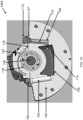
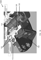
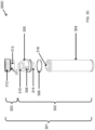
- FIG. 1A and 1B illustrate cross-sectional and perspective cutaway views of the bearing housing of an example ball-bearing pump assembly with a two-piece filter assembly, arranged in accordance with at least some embodiments described herein.
- Ball-ball bearing pump assembly 100A in FIG. 1A includes a bearing housing 102, first filter cavity 104, first plug 106, sump 108, second filter cavity 109, two-piece filter assembly 110, second plug 112 of the two-piece filter assembly 110, oil channel 114, oil path 116, ball bearings 118, shaft 120, and direction of shaft rotation 122.
- the pump assembly 100A is an example of a dual rotation pump, where the shaft may be configured to rotate clockwise or counterclockwise.
- the bearing housing 102 includes two filter cavities (104, 109) for the two-piece filter assembly 110 to be placed in depending on a rotation direction 122 of the shaft 120.
- the shaft 120 is shown as rotating clockwise and the two-piece filter assembly 110 is placed in filter cavity 109.
- First plug 106 is used to cover the empty first filter cavity 104.
- the shaft 120 is surrounded by the ball bearings 118. As the shaft 120 rotates, oil used to lubricate the ball bearings 118 is picked up by the oil ring 128 (shown in FIG.
- the first filter cavity 104, the sump 108, the second filter cavity 109, the oil channel 114, and the oil path 116 are defined by housing wall portions within the bearing housing 102.
- Bearings reduce friction for moving or rotating parts and allow the parts to move or rotate smoothly.
- the shaft is keyed to an impeller and moves fluids through the pump assembly by rotating the impeller.
- Ball bearings 118 allow the shaft 120 to rotate freely.
- a ball bearing is a category of bearings that utilize spherical balls.
- a ball bearing may be made of an inner and outer race, with a series of balls between them, and a cage to hold the balls in place.
- Various parts of a ball bearing may be made from hardened steel and finished with precision.
- ball bearings may operate with simple and inexpensive lubrication such as by oil bath, oil mist, or oil rings. Their narrow width may allow ball bearings to fit in compact housings, making the span of the shaft and bearing combination shorter, and resulting in lower shaft deflections.
- a rotating shaft may encounter two types of forces or thrust loads. These are the axial thrust loads acting along the axis of the shaft and the radial thrust loads acting perpendicular to the axis of the shaft. For example, a major thrust on a shaft operating a centrifugal pump may be predominantly radial. Gravity may also play a role depending on whether the shaft is oriented vertically or horizontally. A vertical orientation may result in greater axial thrust, while a horizontal shaft may encounter higher radial thrust. As ball bearings can carry both axial and radial loads, they may be suitable for use in angular contacts.
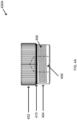
- Shown portions of the ball-ball bearing pump assembly 100B in FIG. 1B include bearing housing 102, second plug 112 of the two-piece filter assembly (not shown in this figure), the shaft 120, ball bearings 118 around the shaft 120, oil path 116, and an oil ring 128.
- lubrication oil is thrown (132) by the oil ring 128 into the oil path 116, travels down the oil path (134) to enter the filter assembly (136).
- oil may travel down the oil path 116 via a gravity feed, or alternatively by oil pressure caused by the combination of the bearing assembly and the rotating shaft 120.
- the two-piece filter assembly may be secured in the filter cavity through threads on an outside surface of the second plug 112 or another securing mechanism.
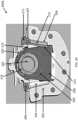
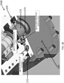
- FIG. 2A and 2B illustrate cross-sectional and perspective cutaway views of the bearing housing of an example sleeve-bearing pump assembly with a two-piece filter assembly, arranged in accordance with at least some embodiments described herein.
- Sleeve-Ball-bearing pump assembly 200A in FIG. 2A includes a bearing housing 202, first filter cavity 204, first plug 206, sump 208, second filter cavity 209, two-piece filter assembly 210, second plug 212 of the two-piece filter assembly 210, oil channel 214, oil path 216, sleeve bearings 218, shaft 220, and direction of shaft rotation 222 and oil ring 228.
- the shaft 220 may be configured to rotate clockwise or counterclockwise, and the two-piece filter assembly 210 is placed in one of the two filter cavities (204, 209) depending on the rotation direction 222 of the shaft 220 such as filter cavity 209 in the illustrated example configuration.
- First plug 206 is used to cover the empty first filter cavity 204.
- the shaft 220 is surrounded by the sleeve bearings 218. As the shaft 220 rotates, oil used to lubricate the sleeve bearings 218 is picked up from the oil ring 228 and is thrown to the oil path 216, which catches the oil and fills up. The oil is then gravity fed to the filter adapter annulus 207, in some examples. The oil then travels down through the two-piece filter 210 and comes out through the oil channel 214 into the sump 208.
- the bearing housing may include multiple recirculation channels, paths, and/or ports.
- a sleeve bearing (also referred to as journal bearing) is a category of bearings that utilize substantially cylindrical sleeves.
- Sleeve bearings are shaped as a sleeve on the shaft. A small clearance exists between the bearing and the shaft, with a lubricant filling the space.
- Sleeve bearings may be made from porous, powdered metal using a sintering process, in some examples. Compared to relatively compact ball bearings, the sleeve bearing may be longer in an axial direction. While ball bearings can carry both radial and axial thrust loads, sleeve bearings are specifically meant to carry radial thrust loads, as they have no capacity to carry axial thrust loads. Sleeve bearings may have practically unlimited radial thrust capacity. However, they are more suitable for use in moderate to high-speed applications. Sleeve bearings may offer better stiffness than ball bearings do, and as they have split halves, they are easier to inspect or replace.
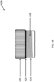
- Shown portions of the sleeve-ball-bearing pump assembly 200B in FIG. 2B include bearing housing 202, second plug 212 of the two-piece filter assembly (not shown in this figure), sleeve bearing 218 (shown empty without the shaft 220), oil path 216, and an oil ring 228.
- lubrication oil is picked by the oil ring 228 and is thrown to the oil path 216 (232), which catches the oil and fills up.
- the oil is gravity fed (234) to the filter adapter annulus 207 (236). The oil then travels down through the two-piece filter 210 and comes out through the oil channel 214 and into the sump 208.
- FIG. 3A illustrates an external side view of an example two-piece filter assembly, arranged in accordance with at least some embodiments described herein.
- Diagram 300A in FIG. 3A shows a two-piece filter assembly 301.
- Two-piece filter assembly 301 includes a plug portion 303 and a filter portion 302.
- Filter portion 302 has a filter medium 304, adapter 305, O-ring 306, filter adapter annulus 308, and top ring 310.
- the plug portion 303 may be coupled to the filter portion 302.
- the plug portion 303 may include a plug 312, with an adapter top ring hole 309, and an O-ring 311.
- the plug portion 303 may be placed over the top ring 310 in some examples.
- a top segment of the plug portion 303 may be knurled for manual removal or placement of the two-piece filter assembly.
- the two-piece filter assembly 301 may be placed in a filter cavity defined by a portion of the bearing housing wall and be fluidically coupled between the oil sump and the oil path.
- the two-piece filter assembly 301 is configured to receive the contaminated oil thrown by the oil ring to the oil path, pass through the filter, and provide filtered oil to the sump.
- Filter medium 304 of the filter portion 302 may be made from a porous filter medium such as microscopic cellulose fibers along with synthetic fibers (e.g., glass or polyester). In some examples, the medium may be saturated with resin for strength and stiffness. A body of the filter medium 304 may be shaped through folding (e.g., pleats) to increase a total surface area, and thereby, an efficiency of the filter. In an operation, contaminated oil flowing from the oil path 116 through the filter adapter annulus 308 into the space inside the filter medium 304 may pass through the filter medium 304 into a gap between the filter portion 302 and surrounding filter cavity (e.g., filter cavity 109), becoming filtered in the process.
- filter cavity e.g., filter cavity 109
- Gravity may pass the clean (filtered) oil in the gap through the oil channel and into the sump of the bearing housing.
- the plug portion 303 and the filter portion 302 may be coupled together through two sets of matching threads, a click-on type mechanism, a pressure-based mechanism, or similar ones.
- a two-piece filter assembly may allow replacement of the filter portion without discarding the plug portion.
- the plug portion 303 and adapter 305 may be made from metal and non-metal parts. To provide a long-lasting plug portion, intricate details may be designed into the parts. Thus, the plug portion may be a relatively expensive component.
- the filter portion may be made from replaceable, relatively low-cost materials. Thus, cost efficiency may be achieved by replacing only the filter portion instead of the entire filter assembly. Furthermore, environmental concerns may be addressed by avoiding frequent disposal of the plug portion along with the filter assembly.
- the filter portion may be made from paper and be easily recyclable as opposed to mainly metal plug portion.
- FIG. 3B illustrates a cross-sectional side view of an example two-piece filter assembly, arranged in accordance with at least some embodiments described herein.
- two-piece filter assembly 301 is shown with filter portion 302, filter medium 304, a collection space 318 inside the filter portion 302, adapter annulus hole 308, O-ring 306, stem 314 of the adapter 305, and securing mechanism location 316.
- Diagram 300B also shows moisture absorbing beads or crystals 315 at the bottom of the filter portion 302.
- the plug portion 303 includes a plug 312, with an adapter top ring hole 309, and an O-ring 311.
- an inside surface 317 of the filter portion which may have a cylindrical or oblong cross section, may be lined with a metal or similar hard material to provide strength and durability to the filter portion.
- the lining material may include openings (e.g., hole of varying sizes and shapes) to allow filtered oil to seep out of the collection space 318.
- Filter adapter annulus 308 provides a path for the oil to flow into the filter assembly and out to the sump as discussed previously.
- Securing mechanism location 316 may hold the adapter 305 and the filter portion together.
- the illustrated example configuration may represent two or more screws that may hold the two components of the two-piece filter assembly 301 together. In other examples, two sets of complementary threads may secure the two components.
- shavings from the bearings may accumulate in the lubrication oil and be filtered by the filter assembly.
- Water from condensation or leakage may also accumulate in the lubrication oil and may not necessarily be filtered by the filter portion 302.
- Moisture absorbing beads 315 or similar dehumidifying material e.g., crystals
- FIG. 3C illustrates an assembly view of an example two-piece filter assembly, arranged in accordance with at least some embodiments described herein.
- the assembly view shown in diagram 300C includes two-piece filter assembly 301 with plug portion 303 and filter portion 302.
- Plug portion 303 includes O-ring 311, plug 312, and top ring adapter 313.
- Filter portion 302 includes top ring 310, adapter annulus hole 308, stem 314, O-ring 306, adapter 305, and filter medium 304 along with collection space 318 inside the filter medium 304.
- An external circumference of the plug stem 314 and an internal circumference of the opening of collection space 318 may be selected such that the plug stem 314 is configured to fit snuggly inside the opening of collection space 318 and to maintain the moisture absorbing beads 315 in the filter portion 302.
- the O-ring 306 may provide a seal between the adapter 305 and the cavity to direct the contaminated oil through the filter.
- the plug portion 303 may be made from metal, metal alloy, ceramic, or similar materials
- the filter portion 302 specifically, filter medium 304 may be made from lower cost, recyclable materials such as various forms of paper, fabric, etc.
- FIG. 4A illustrates a side view of a plug that forms a part of an example two-piece filter assembly, arranged in accordance with at least some embodiments described herein.
- Diagram 400A shows a plug portion of the two-piece filter assembly with a cap portion 402, lower plug housing portion 404 with threads 408 on the lower plug housing portion 404, O-ring 410, and top ring hole 406.
- the cap portion 402 may be knurled for manual placement and removal. Threads 408 on the lower plug housing portion 404 may allow the filter assembly to be secured into the filter cavity by mating with a complementary set of threads on an inside surface of the filter cavity and allowing the assembly to be installed hand tight.
- FIG. 4B illustrates a side view of a plug for an empty filter cavity of a bearing housing, arranged in accordance with at least some embodiments described herein.
- Plug 400B includes a cap portion 422, a lower plug housing portion 424, O-ring 420, and threads 428 on the lower plug housing portion 424.
- Cap portion 422 may include knurls to allow manual placement and removal of the plug.
- Threads 428 on an outside surface of the lower plug housing portion 424 may be used with a complementary set of threads on an inside surface of a top portion of the empty filter cavity to secure the plug onto the filter cavity.
- a click-on securing mechanism may be used in place of the threads.
- one or more screws or similar mechanisms may be used as well.
- Plug 400B may be used as a passive plug on the empty filter cavity.
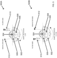
- FIG. 5 illustrates shaft rotation dependent assembly of a bearing housing with a two-piece filter assembly, arranged in accordance with at least some embodiments described herein.
- bearing housing 502 includes sump 506, shaft 504, first filter cavity 508, second filter cavity 509, two-piece filter assembly 510, and plug 512. Because of the clockwise rotation of the shaft 504, the two-piece filter assembly 510 is placed in the first filter cavity 508. The empty second filter cavity 509 is covered with plug 512. As shown in the diagram, the filter assembly 510 may be secured in the first filter cavity 508 through two sets of matching threads on the filter assembly and on an inside surface of the filter cavity. In other examples, the two-piece filter assembly may be secured through a click-on, or screw-on type mechanism, as well.
- bearing housing 502 includes sump 506, shaft 504, first filter cavity 508, second filter cavity 509, two-piece filter assembly 510, and plug 512. Because of the counterclockwise rotation of the shaft 504, the two-piece filter assembly 510 is placed in the second filter cavity 509. The empty first filter cavity 508 is covered with plug 512.
- shaft rotation direction of a pump may be reversed one or more times during an operational life of the pump. As the two-piece filter assembly 510 is configured to be removed and replaced (filter portion) easily, the location of the filter assembly may also be changed in case of shaft rotation direction reversal.
- lower cost filter portion may be replaced with ease (e.g., manually) at higher frequency compared to higher cost full filter replacements, and thereby allow enhancement of the pump assembly's reliability and life expectancy.
- environmental concerns may be addressed by avoiding frequent disposal of the plug portion along with the filter assembly.
- the filter portion may be made from paper or similar recyclable material and frequent replacement may not trigger environmental concerns compared to metal parts of the plug portion.
- any two components herein combined to achieve a particular functionality may be seen as “associated with” each other such that the desired functionality is achieved, irrespective of architectures or intermediate components.
- any two components so associated may also be viewed as being “operably connected”, or “operably coupled”, to each other to achieve the desired functionality, and any two components capable of being so associated may also be viewed as being “operably couplable”, to each other to achieve the desired functionality.
- operably couplable include but are not limited to physically connectable and/or physically interacting components and/or wirelessly interactable and/or wirelessly interacting components and/or logically interacting and/or logically interactable components.
- ranges disclosed herein also encompass any and all possible subranges and combinations of subranges thereof. Any listed range can be easily recognized as sufficiently describing and enabling the same range being broken down into at least equal halves, thirds, quarters, fifths, tenths, etc. As a non-limiting example, each range discussed herein can be readily broken down into a lower third, middle third and upper third, etc. As will also be understood by one skilled in the art all language such as “up to,” “at least,” “greater than,” “less than,” and the like include the number recited and refer to ranges which can be subsequently broken down into subranges as discussed above. Finally, a range includes each individual member. Thus, for example, a group having 1-3 cells refers to groups having 1, 2, or 3 cells. Similarly, a group having 1-5 cells refers to groups having 1, 2, 3, 4, or 5 cells, and so forth.
Landscapes
- Engineering & Computer Science (AREA)
- General Engineering & Computer Science (AREA)
- Chemical & Material Sciences (AREA)
- Mechanical Engineering (AREA)
- Chemical Kinetics & Catalysis (AREA)
- Oil, Petroleum & Natural Gas (AREA)
- Combustion & Propulsion (AREA)
- Structures Of Non-Positive Displacement Pumps (AREA)
- Compressor (AREA)
- Rolling Contact Bearings (AREA)
- Filtration Of Liquid (AREA)
- Centrifugal Separators (AREA)
- Details Of Reciprocating Pumps (AREA)
- Lubrication Details And Ventilation Of Internal Combustion Engines (AREA)
Claims (13)
- Appareil comprenant :
un boîtier pour un ensemble pompe centrifuge, le boîtier comprenant :une première partie de paroi de boîtier qui définit une chambre (102) formée à l'intérieur de celle-ci, ladite chambre étant conçue pour recevoir une combinaison d'un ensemble palier et d'un arbre à faire tourner ;une seconde partie de paroi de boîtier qui définit un carter (108) formé à l'intérieur de celle-ci et couplé fluidiquement à la chambre, ledit carter étant conçu pour recevoir de l'huile filtrée en provenance d'un canal ;une troisième partie de paroi de boîtier qui définit le canal (114) formé à l'intérieur de celle-ci et couplé fluidiquement au carter, ledit canal étant conçu pour recevoir l'huile filtrée en provenance d'une cavité de filtre et la distribuer au carter ; etune quatrième partie de paroi de boîtier qui définit la cavité (104) de filtre formée à l'intérieur de celle-ci, distincte du carter et du canal, et couplée fluidiquement au canal, ladite cavité de filtre étant conçue pour recevoir de l'huile contaminée en provenance d'un circuit d'huile et disperser l'huile filtrée dans le canal ;une cinquième partie de paroi de boîtier qui définit une autre cavité (109) de filtre formée à l'intérieur de celle-ci, couplée fluidiquement entre la chambre et le carter, ladite autre cavité de filtre étant conçue pour disperser l'huile filtrée à partir du filtre et la fournir au carter ; etun ensemble filtre amovible (110) comprenant :une partie filtre (302) conçue pour filtrer l'huile contaminée reçue en provenance du circuit d'huile et disperser l'huile filtrée dans le canal de manière efficace pour lubrifier l'ensemble palier dans la chambre lorsque l'arbre tourne, ladite partie filtre étant remplaçable ; etune partie bouchon (301) couplée fluidiquement à la partie filtre et conçue pour faire passer l'huile contaminée du circuit d'huile à la partie filtre, ladite partie bouchon étant réutilisable ; caractérisé en ce quel'ensemble filtre est conçu pour être placé dans la cavité de filtre ou dans l'autre cavité de filtre sur la base d'un sens de rotation de l'arbre. - Appareil de la revendication 1, ledit ensemble filtre comprenant en outre un ensemble de filets sur une première partie d'une surface extérieure de la partie bouchon et étant conçu pour être fixé à la cavité de filtre par l'intermédiaire d'un autre ensemble de filets complémentaires sur une surface intérieure de la cavité de filtre.
- Appareil de la revendication 2, une seconde partie d'une surface extérieure de la partie bouchon étant moletée pour le placement et le retrait manuels de l'ensemble filtre.
- Appareil de la revendication 1, ladite partie bouchon comprenant une partie adaptateur qui définit un trou de bouchon conçu pour faire passer l'huile contaminée du circuit d'huile à l'intérieur du boîtier vers la partie filtre.
- Appareil de la revendication 1, ledit ensemble filtre comprenant en outre une pluralité de billes absorbant l'humidité à l'intérieur de la partie filtre pour éliminer l'humidité de l'huile.
- Appareil de la revendication 1, ledit ensemble palier étant l'un d'un ensemble palier à billes et un ensemble palier à manchon et à billes.
- Ensemble pompe centrifuge (100A) comprenant :une pompe ;un appareil selon la revendication 1, ledit boîtier de l'appareil étant mécaniquement couplé à la pompe.
- Ensemble pompe de la revendication 7, ladite huile contaminée et ladite huile filtrée circulant à travers l'ensemble filtre par une alimentation par gravité ou par une pression d'huile engendré par l'ensemble palier et l'arbre rotatif.
- Ensemble pompe de la revendication 7, ladite seconde cavité de filtre étant fermée avec un bouchon passif lorsque l'ensemble filtre est placé dans la première cavité de filtre.
- Ensemble pompe de la revendication 7, ladite partie filtre comprenant un matériau de revêtement sensiblement cylindrique et un milieu filtrant plissé qui enveloppe le matériau de revêtement, le matériau de revêtement comportant une pluralité de trous pour que l'huile filtrée s'échappe de la partie filtrante.
- Ensemble pompe de la revendication 7, ladite partie bouchon comprenant :une partie capuchon moletée ; etune partie de boîtier de bouchon filetée.
- Ensemble pompe de la revendication 7, comprenant en outre :
une bague de lubrification à l'intérieur de la chambre, la bague de lubrification étant conçue pour tourner avec l'arbre et projeter l'huile contaminée dans le circuit d'huile. - Procédé permettant la fabrication d'un système de palier de pompe centrifuge, le procédé comprenant :la formation d'une chambre à l'intérieur d'une première partie de paroi de boîtier d'un boîtier de palier pour recevoir une combinaison d'un ensemble palier et d'un arbre à faire tourner ;la formation d'un carter à l'intérieur d'une seconde partie de paroi de boîtier du boîtier de palier en communication fluidique avec la chambre pour fournir de l'huile filtrée à la chambre ;la formation d'une première cavité de filtre à l'intérieur d'une troisième partie de paroi de boîtier du boîtier de palier pour recevoir l'huile contaminée en provenance de la chambre à travers un chemin d'huile et pour disperser l'huile filtrée vers le carter à travers un canal d'huile ;la formation d'une seconde cavité de filtre à l'intérieur d'une quatrième partie de paroi de boîtier du boîtier de palier pour recevoir l'huile contaminée en provenance de la chambre à travers un autre circuit d'huile et pour disperser l'huile filtrée vers le carter à travers un autre canal d'huile ;la construction d'un ensemble filtre en couplant fluidiquement une partie filtre remplaçable à un adaptateur d'une partie bouchon réutilisable, la partie bouchon conçue pour fixer l'ensemble filtre dans la première ou la seconde cavité de filtre et diriger l'huile contaminée reçue vers l'ensemble filtre, et la partie filtre conçue pour filtrer l'huile contaminée et disperser l'huile filtrée vers le carter, de manière efficace pour lubrifier l'ensemble palier lorsque l'arbre tourne ; etle placement de manière amovible de l'ensemble filtre dans la première cavité de filtre ou la seconde cavité de filtre sur la base d'un sens de rotation de l'arbre.
Applications Claiming Priority (1)
| Application Number | Priority Date | Filing Date | Title |
|---|---|---|---|
| PCT/US2020/017144 WO2021158231A1 (fr) | 2020-02-07 | 2020-02-07 | Ensemble filtre à huile en deux parties pour pompes |
Publications (3)
| Publication Number | Publication Date |
|---|---|
| EP4100657A1 EP4100657A1 (fr) | 2022-12-14 |
| EP4100657A4 EP4100657A4 (fr) | 2023-11-01 |
| EP4100657B1 true EP4100657B1 (fr) | 2024-07-17 |
Family
ID=77200218
Family Applications (1)
| Application Number | Title | Priority Date | Filing Date |
|---|---|---|---|
| EP20917934.0A Active EP4100657B1 (fr) | 2020-02-07 | 2020-02-07 | Ensemble filtre à huile en deux parties pour pompes |
Country Status (13)
| Country | Link |
|---|---|
| US (1) | US20230048325A1 (fr) |
| EP (1) | EP4100657B1 (fr) |
| JP (1) | JP7622080B2 (fr) |
| KR (1) | KR20220139890A (fr) |
| CN (1) | CN115087810B (fr) |
| AU (1) | AU2020427546B2 (fr) |
| BR (1) | BR112022015383A2 (fr) |
| CA (1) | CA3169277A1 (fr) |
| CO (1) | CO2022012629A2 (fr) |
| DK (1) | DK4100657T3 (fr) |
| MX (1) | MX2022009695A (fr) |
| PE (1) | PE20230483A1 (fr) |
| WO (1) | WO2021158231A1 (fr) |
Family Cites Families (17)
| Publication number | Priority date | Publication date | Assignee | Title |
|---|---|---|---|---|
| US2877902A (en) * | 1956-03-01 | 1959-03-17 | Fram Corp | Oil filters |
| US4183591A (en) * | 1978-06-29 | 1980-01-15 | Thermo King Corporation | Recirculating bearing oil filter assembly |
| US5150769A (en) * | 1986-01-13 | 1992-09-29 | Hy-Tech Hydraulics, Inc. | Controlled-flow lubricating system |
| CA1290708C (fr) * | 1986-01-13 | 1991-10-15 | Hy-Tech Hydraulics, Inc. | Paliers autolubrifiants et autonettoyants |
| JPH0633247Y2 (ja) * | 1988-05-30 | 1994-08-31 | 株式会社クボタ | 車輌のオイルフイルタ装置 |
| US5733048A (en) * | 1996-07-29 | 1998-03-31 | Reliance Electric Industrial Company | Bearing system including lubricant circulation apparatus |
| JP2000318688A (ja) * | 1999-05-13 | 2000-11-21 | Aisin Seiki Co Ltd | 船内外機 |
| DE102007052644A1 (de) * | 2007-11-05 | 2009-05-07 | Continental Automotive Gmbh | Scheibenreinigungsanlage für Scheiben eines Kraftfahrzeuges |
| GB2469101B (en) * | 2009-04-02 | 2015-10-21 | Cummins Turbo Tech Ltd | A rotating machine with shaft sealing arrangement |
| DE102009033624A1 (de) * | 2009-07-17 | 2011-01-20 | Schaeffler Technologies Gmbh & Co. Kg | Lageranordnung mit einem mediengeschmierten Lager |
| EP2662572A1 (fr) * | 2012-05-09 | 2013-11-13 | Sulzer Pumpen Ag | Agencement d'étanchéité pour le lubrifiant d'un roulement à billes dans une machine fluidique |
| GB2528914B (en) * | 2014-08-04 | 2016-06-15 | A E S Eng Ltd | Bearing lubrication system |
| US9683458B2 (en) * | 2015-08-20 | 2017-06-20 | Pratt & Whitney Canada Corp. | Oil scupper system for bearing housing of gas turbine engine |
| JP2020073807A (ja) * | 2017-03-08 | 2020-05-14 | 日立オートモティブシステムズ株式会社 | バランサ装置とオイルポンプ及びバランサシャフト軸受部の潤滑システム |
| GB2560721B (en) * | 2017-03-21 | 2021-01-06 | Bamford Excavators Ltd | An oil filter assembly |
| US10648509B2 (en) * | 2017-05-30 | 2020-05-12 | Itt Manufacturing Enterprises Llc. | Oil filter/liquid indicator assembly |
| JP2019039559A (ja) * | 2017-08-24 | 2019-03-14 | 株式会社荏原製作所 | 軸受装置 |
-
2020
- 2020-02-07 MX MX2022009695A patent/MX2022009695A/es unknown
- 2020-02-07 DK DK20917934.0T patent/DK4100657T3/da active
- 2020-02-07 BR BR112022015383A patent/BR112022015383A2/pt unknown
- 2020-02-07 EP EP20917934.0A patent/EP4100657B1/fr active Active
- 2020-02-07 PE PE2022001527A patent/PE20230483A1/es unknown
- 2020-02-07 WO PCT/US2020/017144 patent/WO2021158231A1/fr not_active Ceased
- 2020-02-07 US US17/794,319 patent/US20230048325A1/en active Pending
- 2020-02-07 KR KR1020227027490A patent/KR20220139890A/ko not_active Ceased
- 2020-02-07 CN CN202080095578.3A patent/CN115087810B/zh active Active
- 2020-02-07 JP JP2022547986A patent/JP7622080B2/ja active Active
- 2020-02-07 AU AU2020427546A patent/AU2020427546B2/en active Active
- 2020-02-07 CA CA3169277A patent/CA3169277A1/fr active Pending
-
2022
- 2022-09-05 CO CONC2022/0012629A patent/CO2022012629A2/es unknown
Also Published As
| Publication number | Publication date |
|---|---|
| AU2020427546A1 (en) | 2022-08-04 |
| EP4100657A1 (fr) | 2022-12-14 |
| MX2022009695A (es) | 2022-09-07 |
| CN115087810A (zh) | 2022-09-20 |
| US20230048325A1 (en) | 2023-02-16 |
| CA3169277A1 (fr) | 2021-08-12 |
| JP7622080B2 (ja) | 2025-01-27 |
| DK4100657T3 (da) | 2024-09-09 |
| AU2020427546B2 (en) | 2025-09-18 |
| JP2023517282A (ja) | 2023-04-25 |
| BR112022015383A2 (pt) | 2022-09-27 |
| PE20230483A1 (es) | 2023-03-21 |
| KR20220139890A (ko) | 2022-10-17 |
| CO2022012629A2 (es) | 2022-09-20 |
| WO2021158231A1 (fr) | 2021-08-12 |
| CN115087810B (zh) | 2025-02-18 |
| EP4100657A4 (fr) | 2023-11-01 |
Similar Documents
| Publication | Publication Date | Title |
|---|---|---|
| RU2659420C2 (ru) | Компрессор для хладагента | |
| US20020128140A1 (en) | Free Jet centrifuge rotor | |
| KR20080087117A (ko) | 고체 물질을 포함하는 오염액을 배출하기 위한 펌프 | |
| JPS5834227A (ja) | 動圧形流体軸受 | |
| WO2006088054A1 (fr) | Dispositif de palier a roulement | |
| CA2328917C (fr) | Centrifugeuse a jet libre | |
| JP5600555B2 (ja) | フィルタ付き転がり軸受 | |
| EP1011873B1 (fr) | Dispositif d'etancheite d'un separateur centrifuge | |
| EP4100657B1 (fr) | Ensemble filtre à huile en deux parties pour pompes | |
| US7597658B2 (en) | Centrifugal separator and rotor therefor | |
| EP0239962B1 (fr) | Dispositif d'entraînement pour mélangeur | |
| EP0073281B1 (fr) | Palier | |
| US20080296212A1 (en) | Centrifuge For Cleaning a Liquid | |
| JP2016166625A (ja) | フィルタ付転がり軸受 | |
| OA20956A (en) | Two-piece oil filter assembly for pumps | |
| CN107810038B (zh) | 旋转的聚结器 | |
| CN111396566B (zh) | 一种轴端密封结构及布料机 | |
| KR20180107943A (ko) | 오일 시일 구조체 | |
| TWM559547U (zh) | 馬達冷卻液甩油迴流裝置 | |
| JPH083756Y2 (ja) | 二軸回転体の漏出潤滑油排除構造 | |
| JP2011220454A (ja) | グリース潤滑式玉軸受の保持器 | |
| CN216343456U (zh) | 一种耐磨效果好的轴承保持架 | |
| EP1071512B1 (fr) | Centrifugeuse a jet libre | |
| US10899173B2 (en) | Bearing assembly | |
| JPS6110112A (ja) | 水中軸受装置 |
Legal Events
| Date | Code | Title | Description |
|---|---|---|---|
| STAA | Information on the status of an ep patent application or granted ep patent |
Free format text: STATUS: THE INTERNATIONAL PUBLICATION HAS BEEN MADE |
|
| PUAI | Public reference made under article 153(3) epc to a published international application that has entered the european phase |
Free format text: ORIGINAL CODE: 0009012 |
|
| STAA | Information on the status of an ep patent application or granted ep patent |
Free format text: STATUS: REQUEST FOR EXAMINATION WAS MADE |
|
| 17P | Request for examination filed |
Effective date: 20220727 |
|
| AK | Designated contracting states |
Kind code of ref document: A1 Designated state(s): AL AT BE BG CH CY CZ DE DK EE ES FI FR GB GR HR HU IE IS IT LI LT LU LV MC MK MT NL NO PL PT RO RS SE SI SK SM TR |
|
| DAV | Request for validation of the european patent (deleted) | ||
| DAX | Request for extension of the european patent (deleted) | ||
| A4 | Supplementary search report drawn up and despatched |
Effective date: 20230928 |
|
| RIC1 | Information provided on ipc code assigned before grant |
Ipc: B01D 29/90 20060101ALI20230922BHEP Ipc: F16N 39/06 20060101ALI20230922BHEP Ipc: F16C 33/10 20060101ALI20230922BHEP Ipc: B01D 35/30 20060101ALI20230922BHEP Ipc: B01D 29/23 20060101ALI20230922BHEP Ipc: B01D 27/06 20060101ALI20230922BHEP Ipc: F16N 7/22 20060101ALI20230922BHEP Ipc: F16C 33/66 20060101AFI20230922BHEP |
|
| GRAP | Despatch of communication of intention to grant a patent |
Free format text: ORIGINAL CODE: EPIDOSNIGR1 |
|
| STAA | Information on the status of an ep patent application or granted ep patent |
Free format text: STATUS: GRANT OF PATENT IS INTENDED |
|
| INTG | Intention to grant announced |
Effective date: 20240325 |
|
| P01 | Opt-out of the competence of the unified patent court (upc) registered |
Effective date: 20240417 |
|
| GRAS | Grant fee paid |
Free format text: ORIGINAL CODE: EPIDOSNIGR3 |
|
| GRAA | (expected) grant |
Free format text: ORIGINAL CODE: 0009210 |
|
| STAA | Information on the status of an ep patent application or granted ep patent |
Free format text: STATUS: THE PATENT HAS BEEN GRANTED |
|
| AK | Designated contracting states |
Kind code of ref document: B1 Designated state(s): AL AT BE BG CH CY CZ DE DK EE ES FI FR GB GR HR HU IE IS IT LI LT LU LV MC MK MT NL NO PL PT RO RS SE SI SK SM TR |
|
| REG | Reference to a national code |
Ref country code: CH Ref legal event code: EP |
|
| REG | Reference to a national code |
Ref country code: DE Ref legal event code: R096 Ref document number: 602020034306 Country of ref document: DE |
|
| REG | Reference to a national code |
Ref country code: IE Ref legal event code: FG4D |
|
| REG | Reference to a national code |
Ref country code: DK Ref legal event code: T3 Effective date: 20240902 |
|
| REG | Reference to a national code |
Ref country code: NL Ref legal event code: FP |
|
| REG | Reference to a national code |
Ref country code: LT Ref legal event code: MG9D |
|
| PG25 | Lapsed in a contracting state [announced via postgrant information from national office to epo] |
Ref country code: PT Free format text: LAPSE BECAUSE OF FAILURE TO SUBMIT A TRANSLATION OF THE DESCRIPTION OR TO PAY THE FEE WITHIN THE PRESCRIBED TIME-LIMIT Effective date: 20241118 |
|
| PG25 | Lapsed in a contracting state [announced via postgrant information from national office to epo] |
Ref country code: PT Free format text: LAPSE BECAUSE OF FAILURE TO SUBMIT A TRANSLATION OF THE DESCRIPTION OR TO PAY THE FEE WITHIN THE PRESCRIBED TIME-LIMIT Effective date: 20241118 |
|
| PG25 | Lapsed in a contracting state [announced via postgrant information from national office to epo] |
Ref country code: NO Free format text: LAPSE BECAUSE OF FAILURE TO SUBMIT A TRANSLATION OF THE DESCRIPTION OR TO PAY THE FEE WITHIN THE PRESCRIBED TIME-LIMIT Effective date: 20241017 |
|
| PG25 | Lapsed in a contracting state [announced via postgrant information from national office to epo] |
Ref country code: FI Free format text: LAPSE BECAUSE OF FAILURE TO SUBMIT A TRANSLATION OF THE DESCRIPTION OR TO PAY THE FEE WITHIN THE PRESCRIBED TIME-LIMIT Effective date: 20240717 Ref country code: PL Free format text: LAPSE BECAUSE OF FAILURE TO SUBMIT A TRANSLATION OF THE DESCRIPTION OR TO PAY THE FEE WITHIN THE PRESCRIBED TIME-LIMIT Effective date: 20240717 Ref country code: GR Free format text: LAPSE BECAUSE OF FAILURE TO SUBMIT A TRANSLATION OF THE DESCRIPTION OR TO PAY THE FEE WITHIN THE PRESCRIBED TIME-LIMIT Effective date: 20241018 |
|
| PG25 | Lapsed in a contracting state [announced via postgrant information from national office to epo] |
Ref country code: BG Free format text: LAPSE BECAUSE OF FAILURE TO SUBMIT A TRANSLATION OF THE DESCRIPTION OR TO PAY THE FEE WITHIN THE PRESCRIBED TIME-LIMIT Effective date: 20240717 |
|
| PG25 | Lapsed in a contracting state [announced via postgrant information from national office to epo] |
Ref country code: LV Free format text: LAPSE BECAUSE OF FAILURE TO SUBMIT A TRANSLATION OF THE DESCRIPTION OR TO PAY THE FEE WITHIN THE PRESCRIBED TIME-LIMIT Effective date: 20240717 |
|
| PG25 | Lapsed in a contracting state [announced via postgrant information from national office to epo] |
Ref country code: IS Free format text: LAPSE BECAUSE OF FAILURE TO SUBMIT A TRANSLATION OF THE DESCRIPTION OR TO PAY THE FEE WITHIN THE PRESCRIBED TIME-LIMIT Effective date: 20241117 |
|
| PG25 | Lapsed in a contracting state [announced via postgrant information from national office to epo] |
Ref country code: HR Free format text: LAPSE BECAUSE OF FAILURE TO SUBMIT A TRANSLATION OF THE DESCRIPTION OR TO PAY THE FEE WITHIN THE PRESCRIBED TIME-LIMIT Effective date: 20240717 |
|
| PG25 | Lapsed in a contracting state [announced via postgrant information from national office to epo] |
Ref country code: ES Free format text: LAPSE BECAUSE OF FAILURE TO SUBMIT A TRANSLATION OF THE DESCRIPTION OR TO PAY THE FEE WITHIN THE PRESCRIBED TIME-LIMIT Effective date: 20240717 Ref country code: RS Free format text: LAPSE BECAUSE OF FAILURE TO SUBMIT A TRANSLATION OF THE DESCRIPTION OR TO PAY THE FEE WITHIN THE PRESCRIBED TIME-LIMIT Effective date: 20241017 |
|
| PG25 | Lapsed in a contracting state [announced via postgrant information from national office to epo] |
Ref country code: RS Free format text: LAPSE BECAUSE OF FAILURE TO SUBMIT A TRANSLATION OF THE DESCRIPTION OR TO PAY THE FEE WITHIN THE PRESCRIBED TIME-LIMIT Effective date: 20241017 Ref country code: PL Free format text: LAPSE BECAUSE OF FAILURE TO SUBMIT A TRANSLATION OF THE DESCRIPTION OR TO PAY THE FEE WITHIN THE PRESCRIBED TIME-LIMIT Effective date: 20240717 Ref country code: NO Free format text: LAPSE BECAUSE OF FAILURE TO SUBMIT A TRANSLATION OF THE DESCRIPTION OR TO PAY THE FEE WITHIN THE PRESCRIBED TIME-LIMIT Effective date: 20241017 Ref country code: LV Free format text: LAPSE BECAUSE OF FAILURE TO SUBMIT A TRANSLATION OF THE DESCRIPTION OR TO PAY THE FEE WITHIN THE PRESCRIBED TIME-LIMIT Effective date: 20240717 Ref country code: IS Free format text: LAPSE BECAUSE OF FAILURE TO SUBMIT A TRANSLATION OF THE DESCRIPTION OR TO PAY THE FEE WITHIN THE PRESCRIBED TIME-LIMIT Effective date: 20241117 Ref country code: HR Free format text: LAPSE BECAUSE OF FAILURE TO SUBMIT A TRANSLATION OF THE DESCRIPTION OR TO PAY THE FEE WITHIN THE PRESCRIBED TIME-LIMIT Effective date: 20240717 Ref country code: GR Free format text: LAPSE BECAUSE OF FAILURE TO SUBMIT A TRANSLATION OF THE DESCRIPTION OR TO PAY THE FEE WITHIN THE PRESCRIBED TIME-LIMIT Effective date: 20241018 Ref country code: FI Free format text: LAPSE BECAUSE OF FAILURE TO SUBMIT A TRANSLATION OF THE DESCRIPTION OR TO PAY THE FEE WITHIN THE PRESCRIBED TIME-LIMIT Effective date: 20240717 Ref country code: ES Free format text: LAPSE BECAUSE OF FAILURE TO SUBMIT A TRANSLATION OF THE DESCRIPTION OR TO PAY THE FEE WITHIN THE PRESCRIBED TIME-LIMIT Effective date: 20240717 Ref country code: BG Free format text: LAPSE BECAUSE OF FAILURE TO SUBMIT A TRANSLATION OF THE DESCRIPTION OR TO PAY THE FEE WITHIN THE PRESCRIBED TIME-LIMIT Effective date: 20240717 |
|
| PGFP | Annual fee paid to national office [announced via postgrant information from national office to epo] |
Ref country code: NL Payment date: 20250121 Year of fee payment: 6 |
|
| PGFP | Annual fee paid to national office [announced via postgrant information from national office to epo] |
Ref country code: DE Payment date: 20250122 Year of fee payment: 6 |
|
| PG25 | Lapsed in a contracting state [announced via postgrant information from national office to epo] |
Ref country code: SM Free format text: LAPSE BECAUSE OF FAILURE TO SUBMIT A TRANSLATION OF THE DESCRIPTION OR TO PAY THE FEE WITHIN THE PRESCRIBED TIME-LIMIT Effective date: 20240717 Ref country code: RO Free format text: LAPSE BECAUSE OF FAILURE TO SUBMIT A TRANSLATION OF THE DESCRIPTION OR TO PAY THE FEE WITHIN THE PRESCRIBED TIME-LIMIT Effective date: 20240717 |
|
| PGFP | Annual fee paid to national office [announced via postgrant information from national office to epo] |
Ref country code: DK Payment date: 20250121 Year of fee payment: 6 |
|
| REG | Reference to a national code |
Ref country code: DE Ref legal event code: R097 Ref document number: 602020034306 Country of ref document: DE |
|
| PG25 | Lapsed in a contracting state [announced via postgrant information from national office to epo] |
Ref country code: EE Free format text: LAPSE BECAUSE OF FAILURE TO SUBMIT A TRANSLATION OF THE DESCRIPTION OR TO PAY THE FEE WITHIN THE PRESCRIBED TIME-LIMIT Effective date: 20240717 |
|
| PGFP | Annual fee paid to national office [announced via postgrant information from national office to epo] |
Ref country code: AT Payment date: 20250124 Year of fee payment: 6 |
|
| PG25 | Lapsed in a contracting state [announced via postgrant information from national office to epo] |
Ref country code: CZ Free format text: LAPSE BECAUSE OF FAILURE TO SUBMIT A TRANSLATION OF THE DESCRIPTION OR TO PAY THE FEE WITHIN THE PRESCRIBED TIME-LIMIT Effective date: 20240717 |
|
| PGFP | Annual fee paid to national office [announced via postgrant information from national office to epo] |
Ref country code: FR Payment date: 20250122 Year of fee payment: 6 |
|
| PG25 | Lapsed in a contracting state [announced via postgrant information from national office to epo] |
Ref country code: SK Free format text: LAPSE BECAUSE OF FAILURE TO SUBMIT A TRANSLATION OF THE DESCRIPTION OR TO PAY THE FEE WITHIN THE PRESCRIBED TIME-LIMIT Effective date: 20240717 |
|
| PGFP | Annual fee paid to national office [announced via postgrant information from national office to epo] |
Ref country code: GB Payment date: 20250123 Year of fee payment: 6 |
|
| PLBE | No opposition filed within time limit |
Free format text: ORIGINAL CODE: 0009261 |
|
| STAA | Information on the status of an ep patent application or granted ep patent |
Free format text: STATUS: NO OPPOSITION FILED WITHIN TIME LIMIT |
|
| 26N | No opposition filed |
Effective date: 20250422 |
|
| PG25 | Lapsed in a contracting state [announced via postgrant information from national office to epo] |
Ref country code: SE Free format text: LAPSE BECAUSE OF FAILURE TO SUBMIT A TRANSLATION OF THE DESCRIPTION OR TO PAY THE FEE WITHIN THE PRESCRIBED TIME-LIMIT Effective date: 20240717 |
|
| PG25 | Lapsed in a contracting state [announced via postgrant information from national office to epo] |
Ref country code: MC Free format text: LAPSE BECAUSE OF FAILURE TO SUBMIT A TRANSLATION OF THE DESCRIPTION OR TO PAY THE FEE WITHIN THE PRESCRIBED TIME-LIMIT Effective date: 20240717 |
|
| REG | Reference to a national code |
Ref country code: CH Ref legal event code: PL |
|
| PG25 | Lapsed in a contracting state [announced via postgrant information from national office to epo] |
Ref country code: LU Free format text: LAPSE BECAUSE OF NON-PAYMENT OF DUE FEES Effective date: 20250207 |
|
| PG25 | Lapsed in a contracting state [announced via postgrant information from national office to epo] |
Ref country code: CH Free format text: LAPSE BECAUSE OF NON-PAYMENT OF DUE FEES Effective date: 20250228 |
|
| REG | Reference to a national code |
Ref country code: BE Ref legal event code: MM Effective date: 20250228 |
|
| PG25 | Lapsed in a contracting state [announced via postgrant information from national office to epo] |
Ref country code: IT Free format text: LAPSE BECAUSE OF NON-PAYMENT OF DUE FEES Effective date: 20250207 |
|
| PG25 | Lapsed in a contracting state [announced via postgrant information from national office to epo] |
Ref country code: BE Free format text: LAPSE BECAUSE OF NON-PAYMENT OF DUE FEES Effective date: 20250228 |
|
| PG25 | Lapsed in a contracting state [announced via postgrant information from national office to epo] |
Ref country code: IE Free format text: LAPSE BECAUSE OF NON-PAYMENT OF DUE FEES Effective date: 20250207 |