EP4100559B1 - Verfahren zur zuführung eines mit sauerstoff angereicherten gases zu einem sauerstoffverbrauchenden prozesses - Google Patents
Verfahren zur zuführung eines mit sauerstoff angereicherten gases zu einem sauerstoffverbrauchenden prozesses Download PDFInfo
- Publication number
- EP4100559B1 EP4100559B1 EP21703908.0A EP21703908A EP4100559B1 EP 4100559 B1 EP4100559 B1 EP 4100559B1 EP 21703908 A EP21703908 A EP 21703908A EP 4100559 B1 EP4100559 B1 EP 4100559B1
- Authority
- EP
- European Patent Office
- Prior art keywords
- oxygen
- stream
- anode
- cathode
- enriched
- Prior art date
- Legal status (The legal status is an assumption and is not a legal conclusion. Google has not performed a legal analysis and makes no representation as to the accuracy of the status listed.)
- Active
Links
Images


Classifications
-
- C—CHEMISTRY; METALLURGY
- C25—ELECTROLYTIC OR ELECTROPHORETIC PROCESSES; APPARATUS THEREFOR
- C25B—ELECTROLYTIC OR ELECTROPHORETIC PROCESSES FOR THE PRODUCTION OF COMPOUNDS OR NON-METALS; APPARATUS THEREFOR
- C25B1/00—Electrolytic production of inorganic compounds or non-metals
- C25B1/01—Products
- C25B1/02—Hydrogen or oxygen
-
- C—CHEMISTRY; METALLURGY
- C25—ELECTROLYTIC OR ELECTROPHORETIC PROCESSES; APPARATUS THEREFOR
- C25B—ELECTROLYTIC OR ELECTROPHORETIC PROCESSES FOR THE PRODUCTION OF COMPOUNDS OR NON-METALS; APPARATUS THEREFOR
- C25B15/00—Operating or servicing cells
- C25B15/08—Supplying or removing reactants or electrolytes; Regeneration of electrolytes
- C25B15/081—Supplying products to non-electrochemical reactors that are combined with the electrochemical cell, e.g. Sabatier reactor
-
- C—CHEMISTRY; METALLURGY
- C25—ELECTROLYTIC OR ELECTROPHORETIC PROCESSES; APPARATUS THEREFOR
- C25B—ELECTROLYTIC OR ELECTROPHORETIC PROCESSES FOR THE PRODUCTION OF COMPOUNDS OR NON-METALS; APPARATUS THEREFOR
- C25B1/00—Electrolytic production of inorganic compounds or non-metals
- C25B1/01—Products
- C25B1/23—Carbon monoxide or syngas
-
- C—CHEMISTRY; METALLURGY
- C04—CEMENTS; CONCRETE; ARTIFICIAL STONE; CERAMICS; REFRACTORIES
- C04B—LIME, MAGNESIA; SLAG; CEMENTS; COMPOSITIONS THEREOF, e.g. MORTARS, CONCRETE OR LIKE BUILDING MATERIALS; ARTIFICIAL STONE; CERAMICS; REFRACTORIES; TREATMENT OF NATURAL STONE
- C04B2/00—Lime, magnesia or dolomite
- C04B2/10—Preheating, burning calcining or cooling
-
- C—CHEMISTRY; METALLURGY
- C04—CEMENTS; CONCRETE; ARTIFICIAL STONE; CERAMICS; REFRACTORIES
- C04B—LIME, MAGNESIA; SLAG; CEMENTS; COMPOSITIONS THEREOF, e.g. MORTARS, CONCRETE OR LIKE BUILDING MATERIALS; ARTIFICIAL STONE; CERAMICS; REFRACTORIES; TREATMENT OF NATURAL STONE
- C04B7/00—Hydraulic cements
- C04B7/36—Manufacture of hydraulic cements in general
- C04B7/43—Heat treatment, e.g. precalcining, burning, melting; Cooling
-
- C—CHEMISTRY; METALLURGY
- C25—ELECTROLYTIC OR ELECTROPHORETIC PROCESSES; APPARATUS THEREFOR
- C25B—ELECTROLYTIC OR ELECTROPHORETIC PROCESSES FOR THE PRODUCTION OF COMPOUNDS OR NON-METALS; APPARATUS THEREFOR
- C25B1/00—Electrolytic production of inorganic compounds or non-metals
- C25B1/01—Products
- C25B1/02—Hydrogen or oxygen
- C25B1/04—Hydrogen or oxygen by electrolysis of water
- C25B1/042—Hydrogen or oxygen by electrolysis of water by electrolysis of steam
-
- C—CHEMISTRY; METALLURGY
- C25—ELECTROLYTIC OR ELECTROPHORETIC PROCESSES; APPARATUS THEREFOR
- C25B—ELECTROLYTIC OR ELECTROPHORETIC PROCESSES FOR THE PRODUCTION OF COMPOUNDS OR NON-METALS; APPARATUS THEREFOR
- C25B15/00—Operating or servicing cells
- C25B15/02—Process control or regulation
-
- C—CHEMISTRY; METALLURGY
- C25—ELECTROLYTIC OR ELECTROPHORETIC PROCESSES; APPARATUS THEREFOR
- C25B—ELECTROLYTIC OR ELECTROPHORETIC PROCESSES FOR THE PRODUCTION OF COMPOUNDS OR NON-METALS; APPARATUS THEREFOR
- C25B15/00—Operating or servicing cells
- C25B15/08—Supplying or removing reactants or electrolytes; Regeneration of electrolytes
- C25B15/087—Recycling of electrolyte to electrochemical cell
-
- F—MECHANICAL ENGINEERING; LIGHTING; HEATING; WEAPONS; BLASTING
- F23—COMBUSTION APPARATUS; COMBUSTION PROCESSES
- F23L—SUPPLYING AIR OR NON-COMBUSTIBLE LIQUIDS OR GASES TO COMBUSTION APPARATUS IN GENERAL ; VALVES OR DAMPERS SPECIALLY ADAPTED FOR CONTROLLING AIR SUPPLY OR DRAUGHT IN COMBUSTION APPARATUS; INDUCING DRAUGHT IN COMBUSTION APPARATUS; TOPS FOR CHIMNEYS OR VENTILATING SHAFTS; TERMINALS FOR FLUES
- F23L7/00—Supplying non-combustible liquids or gases, other than air, to the fire, e.g. oxygen, steam
- F23L7/007—Supplying oxygen or oxygen-enriched air
-
- C—CHEMISTRY; METALLURGY
- C25—ELECTROLYTIC OR ELECTROPHORETIC PROCESSES; APPARATUS THEREFOR
- C25B—ELECTROLYTIC OR ELECTROPHORETIC PROCESSES FOR THE PRODUCTION OF COMPOUNDS OR NON-METALS; APPARATUS THEREFOR
- C25B13/00—Diaphragms; Spacing elements
- C25B13/04—Diaphragms; Spacing elements characterised by the material
- C25B13/05—Diaphragms; Spacing elements characterised by the material based on inorganic materials
- C25B13/07—Diaphragms; Spacing elements characterised by the material based on inorganic materials based on ceramics
-
- C—CHEMISTRY; METALLURGY
- C25—ELECTROLYTIC OR ELECTROPHORETIC PROCESSES; APPARATUS THEREFOR
- C25B—ELECTROLYTIC OR ELECTROPHORETIC PROCESSES FOR THE PRODUCTION OF COMPOUNDS OR NON-METALS; APPARATUS THEREFOR
- C25B9/00—Cells or assemblies of cells; Constructional parts of cells; Assemblies of constructional parts, e.g. electrode-diaphragm assemblies; Process-related cell features
- C25B9/17—Cells comprising dimensionally-stable non-movable electrodes; Assemblies of constructional parts thereof
- C25B9/19—Cells comprising dimensionally-stable non-movable electrodes; Assemblies of constructional parts thereof with diaphragms
-
- Y—GENERAL TAGGING OF NEW TECHNOLOGICAL DEVELOPMENTS; GENERAL TAGGING OF CROSS-SECTIONAL TECHNOLOGIES SPANNING OVER SEVERAL SECTIONS OF THE IPC; TECHNICAL SUBJECTS COVERED BY FORMER USPC CROSS-REFERENCE ART COLLECTIONS [XRACs] AND DIGESTS
- Y02—TECHNOLOGIES OR APPLICATIONS FOR MITIGATION OR ADAPTATION AGAINST CLIMATE CHANGE
- Y02E—REDUCTION OF GREENHOUSE GAS [GHG] EMISSIONS, RELATED TO ENERGY GENERATION, TRANSMISSION OR DISTRIBUTION
- Y02E20/00—Combustion technologies with mitigation potential
- Y02E20/32—Direct CO2 mitigation
-
- Y—GENERAL TAGGING OF NEW TECHNOLOGICAL DEVELOPMENTS; GENERAL TAGGING OF CROSS-SECTIONAL TECHNOLOGIES SPANNING OVER SEVERAL SECTIONS OF THE IPC; TECHNICAL SUBJECTS COVERED BY FORMER USPC CROSS-REFERENCE ART COLLECTIONS [XRACs] AND DIGESTS
- Y02—TECHNOLOGIES OR APPLICATIONS FOR MITIGATION OR ADAPTATION AGAINST CLIMATE CHANGE
- Y02E—REDUCTION OF GREENHOUSE GAS [GHG] EMISSIONS, RELATED TO ENERGY GENERATION, TRANSMISSION OR DISTRIBUTION
- Y02E20/00—Combustion technologies with mitigation potential
- Y02E20/34—Indirect CO2mitigation, i.e. by acting on non CO2directly related matters of the process, e.g. pre-heating or heat recovery
-
- Y—GENERAL TAGGING OF NEW TECHNOLOGICAL DEVELOPMENTS; GENERAL TAGGING OF CROSS-SECTIONAL TECHNOLOGIES SPANNING OVER SEVERAL SECTIONS OF THE IPC; TECHNICAL SUBJECTS COVERED BY FORMER USPC CROSS-REFERENCE ART COLLECTIONS [XRACs] AND DIGESTS
- Y02—TECHNOLOGIES OR APPLICATIONS FOR MITIGATION OR ADAPTATION AGAINST CLIMATE CHANGE
- Y02E—REDUCTION OF GREENHOUSE GAS [GHG] EMISSIONS, RELATED TO ENERGY GENERATION, TRANSMISSION OR DISTRIBUTION
- Y02E60/00—Enabling technologies; Technologies with a potential or indirect contribution to GHG emissions mitigation
- Y02E60/30—Hydrogen technology
- Y02E60/36—Hydrogen production from non-carbon containing sources, e.g. by water electrolysis
-
- Y—GENERAL TAGGING OF NEW TECHNOLOGICAL DEVELOPMENTS; GENERAL TAGGING OF CROSS-SECTIONAL TECHNOLOGIES SPANNING OVER SEVERAL SECTIONS OF THE IPC; TECHNICAL SUBJECTS COVERED BY FORMER USPC CROSS-REFERENCE ART COLLECTIONS [XRACs] AND DIGESTS
- Y02—TECHNOLOGIES OR APPLICATIONS FOR MITIGATION OR ADAPTATION AGAINST CLIMATE CHANGE
- Y02P—CLIMATE CHANGE MITIGATION TECHNOLOGIES IN THE PRODUCTION OR PROCESSING OF GOODS
- Y02P40/00—Technologies relating to the processing of minerals
- Y02P40/10—Production of cement, e.g. improving or optimising the production methods; Cement grinding
- Y02P40/121—Energy efficiency measures, e.g. improving or optimising the production methods
-
- Y—GENERAL TAGGING OF NEW TECHNOLOGICAL DEVELOPMENTS; GENERAL TAGGING OF CROSS-SECTIONAL TECHNOLOGIES SPANNING OVER SEVERAL SECTIONS OF THE IPC; TECHNICAL SUBJECTS COVERED BY FORMER USPC CROSS-REFERENCE ART COLLECTIONS [XRACs] AND DIGESTS
- Y02—TECHNOLOGIES OR APPLICATIONS FOR MITIGATION OR ADAPTATION AGAINST CLIMATE CHANGE
- Y02P—CLIMATE CHANGE MITIGATION TECHNOLOGIES IN THE PRODUCTION OR PROCESSING OF GOODS
- Y02P40/00—Technologies relating to the processing of minerals
- Y02P40/10—Production of cement, e.g. improving or optimising the production methods; Cement grinding
- Y02P40/18—Carbon capture and storage [CCS]
-
- Y—GENERAL TAGGING OF NEW TECHNOLOGICAL DEVELOPMENTS; GENERAL TAGGING OF CROSS-SECTIONAL TECHNOLOGIES SPANNING OVER SEVERAL SECTIONS OF THE IPC; TECHNICAL SUBJECTS COVERED BY FORMER USPC CROSS-REFERENCE ART COLLECTIONS [XRACs] AND DIGESTS
- Y02—TECHNOLOGIES OR APPLICATIONS FOR MITIGATION OR ADAPTATION AGAINST CLIMATE CHANGE
- Y02P—CLIMATE CHANGE MITIGATION TECHNOLOGIES IN THE PRODUCTION OR PROCESSING OF GOODS
- Y02P40/00—Technologies relating to the processing of minerals
- Y02P40/40—Production or processing of lime, e.g. limestone regeneration of lime in pulp and sugar mills
Definitions
- the present invention relates to a method for supplying an oxygen-enriched gas to an oxygen consuming process, in which the oxygen-enriched gas with a low nitrogen content is generated by supplying an anode-side feed gas comprising CO 2 to the anode side of an operating solid oxide electrolysis cell (SOEC).
- SOEC solid oxide electrolysis cell
- the invention also relates to a solid oxide electrolysis cell supplied with a feed gas comprising CO 2 , wherein the anode side of the cell is in fluid connection with an oxygen-consuming process.
- Oxyfuel combustion is the process of combusting a hydrocarbon fuel in a nitrogen-poor environment, typically in a stream of almost pure oxygen or a mixture of oxygen and carbon dioxide.
- the main purpose for using oxyfuel combustion in e.g. a coal-fired power plant is to generate flue gas with very high concentrations of CO 2 and water vapor, making it possible to separate or capture the CO 2 from the flue gas while avoiding the expensive separation of CO 2 from gaseous nitrogen. It is important to note that even when oxy-combustion is used, the flue gases still contain impurities, such as residual nitrogen, unburnt oxygen, SO 2 , nitrogen oxides and particulate material. Much of this will still have to be removed in order to produce carbon dioxide which is pure enough for carbon capture and storage or for other downstream usage.
- Oxyfuel combustion for CO 2 capture incorporates four main components: 1) an air separation unit (ASU) that provides the oxygen-enriched oxidant stream for combustion, 2) a boiler or a gas turbine, where the fuel is combusted and heat is generated, 3) a flue gas processing unit, where the flue gas is cleared of undesirable species, such as ash, the majority of the sulfur and nitrogen oxides, and 4) a CO 2 processing unit (CPU), where the final purification of the CO 2 for transport, storage and/or utilization is carried out.
- ASU air separation unit
- boiler or a gas turbine where the fuel is combusted and heat is generated
- flue gas processing unit where the flue gas is cleared of undesirable species, such as ash, the majority of the sulfur and nitrogen oxides
- CO 2 processing unit CO 2 processing unit
- the flame temperature is much higher than when the combustion is carried out in air.
- the peak temperature can reach 2500°C compared to 1700°C in a conventional supercritical boiler.
- the combustion temperature is limited to about 1300-1400°C in a typical gas turbine cycle and to about 1900°C in an oxyfuel coal-fired boiler using current technology.
- some of the CO 2 -rich flue gas exiting the boiler is commonly mixed with the oxygen-enriched stream that is supplied to the burners. This dilutes the oxygen and reduces the flame temperature to a level similar to the level found in a conventional air-blown plant.
- NO x nitric oxides
- thermal NO x formation 2) prompt NO x formation and 3 conversion of fuel nitrogen to NO x .
- thermal and prompt NO x formation pathways can often be neglected. Therefore, NO x formation from fuel nitrogen is the most important pathway in boilers using oxyfuel combustion.
- NO x Approximately 95% of the total NO x consists of nitric oxide (NO), the remainder consisting of nitrogen dioxide (NO 2 ) and small amounts of dinitrogen oxide (N 2 O) and other nitrogen oxides.
- Oxygen-enriched streams are also beneficial in oxygen-fired calciners, or oxy-calciners.
- oxygen-fired calciners are gaining a wider interest due to their potential use in e.g. direct air capture plants involving calcium looping.
- direct air capture plants involving calcium looping.
- David W. Keith et al. describe a process for capturing CO 2 from the atmosphere ( Joule 2, 1573-1594 (2018 )). More specifically, a one megaton CO 2 per year plant for direct air capture of CO 2 from the atmosphere is described.
- the process chemistry of said plant is based on two loops: An alkali loop (CO 2 + KOH to K 2 CO 3 to KOH) and a calcium loop (CaCO 3 to CaO + CO 2 to Ca(OH) 2 to CaCO 3 ).
- the CO 2 is captured by reaction with KOH, giving K 2 CO 3 .
- This K 2 CO 3 is reacted with Ca(OH) 2 in order to regenerate KOH and give CaCO 3 , the latter of which is then calcined in an oxygen-fired calciner to release the CO 2 and regenerate the Ca-species.
- the calcination step needs to be carried out in a nitrogen-poor atmosphere, as the CO 2 (released during the calcination) and the N 2 are difficult to separate, once they are mixed.
- the calcium carbonate (CaCO 3 ) formed in the calcium loop is led to the calciner, where this solid material is regenerated back to CaO and CO 2 , the latter of which is led out of the reactor for purification and compression.
- the calciner needs an additional heat source to raise the temperature to around 900°C, which is needed for covering the heat requirement of the endothermic calcination reaction.
- the most obvious way to produce this heat is by using oxyfuel combustion, which produces flue gas containing mostly CO 2 , as described previously.
- the oxyfuel combustion requires an ASU.
- the efficiency of oxy-calciners depends on the oxygen concentration of the oxygen-enriched stream used for the calcination process: the higher the oxygen concentration, the higher the efficiency.
- the advantages from a higher O 2 concentration comes from a lower total gas flow to the furnace, which decreases the heat demand of the furnace.
- a smaller heat demand means a smaller fuel input, which reduces the required oxygen flow.
- a smaller furnace decreases the investment cost of the plant and this is significant, especially in the calcium looping process, where the calciner is an insulated reactor.
- ASUs commonly cryogenic ASUs for providing oxygen-enriched gas streams for the boiler or calciner chambers.
- An ASU is very expensive (in terms of capital expenditure (CAPEX) as well as operating expenditure (OPEX)).
- the ASU consumes approximately 225 kWh energy per tonne of O 2 produced and is one of the most expensive pieces of equipment in oxyfuel combustion plants and oxy-calciner plants.
- the goal of this invention is to provide an alternative method for supplying oxygen-enriched gas to oxygen-consuming processes, such as the oxycombustion or oxy-calciner processes described above.
- the invention proposes that the oxygen-enriched stream with a low nitrogen content is generated by supplying an anode-side feed gas comprising CO 2 to the anode side of an operating solid oxide electrolysis cell (SOEC) whereby an oxygen-enriched anode-side product gas is obtained.
- SOEC solid oxide electrolysis cell
- Solid oxide electrolysis cells can be used to electrochemically reduce H 2 O to H 2 , CO 2 to CO or a combination of H 2 O and CO 2 to syngas (H 2 and CO). This conversion occurs on the cathode (fuel) side of the solid oxide electrolysis cell. On the anode (oxy) side of the cell, oxygen is electrochemically generated.
- electrochemically generated refers to a process where chemical species are formed via an electrochemical process (i.e. a chemical process involving electron transfer). Such processes include e.g.
- WO2018148490 describes a method for producing oxygen and syngas with a high-temperature co-electrolysis (HTCE) unit that may include at least one solid-oxide electrolysis cell.
- HTCE high-temperature co-electrolysis
- the terms “stream”, “gas” and “gas stream” are used interchangeably.
- the term “at least part of” a certain gas stream it is to be understood that either the entire gas stream or a fraction of the stream is used.
- the gas stream may simply be split into fractions of identical composition. It is not meant to refer to a separation of the components of the gas. It may for example be relevant if it is desired to recycle a fraction of the gas stream to the solid oxide electrolysis cell.
- the fraction which is fed to the oxygen/H2/CO consuming process may e.g. be between 5% and as upper limit 10%, 20%, 30%, 40%, 50%, 60%, 70%, 80%, 90% or 100% of the oxygen enriched gas or the H2 and/or CO enriched gas.
- the cathode-side feed gas stream may also be referred to as a fuel feed and the anode-side feed gas stream may also be referred to as a flush feed.
- the cathode-side feed gas comprising H 2 O is fed to the cathode side of an operating SOEC, at least part of the H 2 O is electrochemically reduced into H 2 (i.e. H 2 is electrochemically generated), thereby forming a cathode-side product gas that is enriched in hydrogen.
- the term "enriched in X” is understood as "the concentration of X in a stream is increased compared to the concentration of X in the corresponding feed gas”.
- a cathode-side gas stream enriched in hydrogen (exiting an electrolysis cell) has a higher concentration of hydrogen than the cathode-side feed gas (entering the solid oxide electrolysis cell).
- a cathode-side feed gas comprising CO 2 is fed to the cathode side of an operating SOEC, at least part of the CO 2 is electrochemically reduced into CO (i.e. CO is electrochemically generated), thereby forming a cathode-side product gas that is enriched in CO.
- a cathode-side feed gas comprising a mixture of H 2 O and CO 2 is fed to the cathode side of an operating SOEC, at least part of either H 2 O or CO 2 or both is electrochemically reduced, thereby forming a cathode-side product gas that is enriched in hydrogen and CO.
- an anode-side gas stream enriched in O 2 (exiting an electrolysis cell) has a higher concentration of O 2 than the anode-side feed gas stream (entering the solid oxide electrolysis cell).
- a 10% O 2 , 90% CO 2 anode-side product gas stream may be considered to be enriched in O 2 , if the anode-side feed gas stream has an oxygen content lower than 10%.
- a 10% O 2 , 90% CO 2 anode-side product gas stream is considered to be enriched in O 2 according to the definition, although the oxygen content in the gas is lower than in atmospheric air.
- the typical operating temperature of SOECs is between approximately 600°C and 1000°C: high temperatures are required in order to reach sufficient oxide ion conductivities in the ceramic membranes that are used as electrolytes.
- Commonly used electrolyte materials include stabilized zirconias, such as yttria-stabilized zirconia (YSZ), doped cerias, doped lanthanum gallates, and others.
- oxy-electrode materials include perovskite materials, such as Sr-doped LaMnO 3 (LSM), Sr-doped LaFeO 3 (LSF), Sr-doped LaCoO 3 (LSC), Sr-doped La(Co,Fe)O 3 (LSCF), Sr-doped SmCoO 3 and many others.
- Perovskite materials are further commonly mixed with doped cerias to form composite oxygen electrodes (SOEC anodes). Dopants other than Sr, e.g. Ca, Ba are known, as are materials other than perovskites, e.g. Ruddlesden-Popper phases.
- Applicant's WO 2013/131778 A2 and US 10,494,728 B2 both describe the production of high purity CO by electrolysis of CO 2 in a solid oxide electrolysis cell or SOEC stack.
- air N 2 /O 2
- concentration of O 2 in the gas stream exiting the anode side of the solid oxide electrolysis cell depends on the flow rate of the anode-side feed gas and also the operating current of the SOEC. In principle, close to 100% oxygen can be produced on the anode side, if no feed gas is used or if pure oxygen is used as feed. However, this is normally not done due to the higher risk of degradation of various stack components at high oxygen partial pressures and high temperatures. However, here the advantage obtained is more important than the disadvantage.
- a stream comprising CO 2 with a low nitrogen content is used as feed gas (sometimes also referred to as flush gas) on the anode side of the SOEC instead of air.
- feed gas sometimes also referred to as flush gas
- the resulting product gas is enriched in oxygen and is suitable for use as oxidant in a number of oxygen-consuming processes.
- oxygen-consuming processes refers to processes where oxygen reacts with other chemical species, thereby oxidixing that latter species. Examples of oxygen-consuming processes include oxy-combustion, oxy-calcining and gasification.
- the invention relates to a method for supplying oxygen-enriched gas to an oxygen-consuming process according to claim 1.
- At least one operating solid oxide electro-lysis cell having a cathode side and an anode side, and
- hydrogen- and/or carbon monoxide-consuming process refers to processes, where hydrogen or carbon monoxide or both react to form other chemical species.
- hydrogen- and/or carbon monoxide-consuming processes include methanol production, ammonia production, hydrotreating, methanation, hydrogenation, carbonylation, hydroformulation (oxo synthesis) and oxidative carbonylation.
- the anode-side feed gas stream comprising CO 2 may e.g. comprise 0-100 vol% CO 2 , such as 20-100, 40-100, 50-100, 60-100,70-100, 80-100 vol% CO 2 .
- an oxy-combustion or oxy-combustion process is meant to refer to a process using essentially pure oxygen as oxidant, and importantly the process is conducted in the presence of a low amount of nitrogen (N).
- the oxy-combustion is meant to refer to a full combustion of the fuel resulting in a product gas which is non-reducing. There will not be a remaining heating value in the product gas.
- Gasification is meant to refer to a sub-stoichiometric combustion of the fuel.
- the product gas will be reducing and there will be a remaining heating value in the product gas.
- oxy-calcining is meant to refer to an oxy-combustion process where a solid carbonate is decomposed into the corresponding oxide, e.g. CaCO3 into CaO for producing cement.
- combustion is meant to refer to a chemical species which can be oxidized to produce heat (an exothermic oxidation reaction).
- the anode-side feed gas and/or the cathode side feed gas is heated prior to feeding it to the solid oxide electrolysis cell.
- the oxygen enriched gas is not heated prior to feeding it to the oxygen consuming process. Heating can be dispensed with since the exit temperature of the oxygen enriched gas from the solid oxide electrolysis cell is high, typically above 600 °C, or even above 700, 800 or 900 °C.
- the invention also relates to a solid oxide electrolysis cell, wherein the anode side of the cell is in fluid connection with an oxygen-consuming process, and wherein the cell operates according to the above method.
- the method of the invention has multiple advantages. Firstly, as long as an anode-side feed gas with a low nitrogen content is provided to the anode side of the solid oxide electrolysis cell, the oxygen-enriched stream exiting the cell also has a low nitrogen content, and thereby it is highly suitable for use as oxidant in oxycombustion or in oxy-calciners.
- the nitrogen content in the oxygen-enriched stream is below 10 vol%, such as below 5 vol%, 3 vol%, 2 vol%, 1 vol% or 0.1 vol%. The less nitrogen, the better.
- the nitrogen content in the oxygen-enriched stream is low compared to the nitrogen content in air, the energy requirement (i.e. fuel consumption) for heating the stream to the inlet temperature of the oxygen-consuming process is considerably lower, due to the fact that the nitrogen component of air is not heated.
- the use of oxygen-enriched streams low in nitrogen content allows higher flame temperatures to be achieved in oxy-combustion and oxy-calcination kilns.
- a cryogenic ASU or other ASU is no longer required for air separation. As mentioned above, ASUs are expensive, both in terms of capital costs and in terms of operating expenditures.
- the oxygen-enriched stream exiting the anode-side of the solid oxide electrolysis cell will not require (or will only require very little) pre-heating before entering the oxy-combustion or oxy-calcination kiln, thereby making the process more efficient. It should be noted that oxygen produced using cryogenic air separation would require very significant pre-heating.
- the anode-side feed gas comprising CO 2 that is fed to the anode-side of the solid oxide electrolysis cell needs to be pre-heated, the heating requirement is lower compared to state-of-the-art solutions without an SOEC.
- oxygen that is electrochemically generated and which forms part of the oxygen-enriched stream can be at least partly heated using Joule heat generated by the SOEC.
- the electrochemically generated oxygen which has hitherto often been considered as a low-value side-product of the electrolysis process, can be used instead of venting it, thereby increasing the efficiency and profitability of the electrolysis process. It is therefore particularly advantageous if both product gases from the SOEC are used, i.e. that anode-side product gas enriched in oxygen is used in an oxygen-consuming process and the cathode-side product gas enriched in H 2 and/or CO is simultaneously used in a hydrogen- and/or carbon monoxide-using process.
- the method offers a simple way of controlling the oxygen content in the oxygen-enriched stream entering the oxygen-consuming process. This is because the concentration of O 2 in the gas stream can be easily and rapidly altered by changing the flow rate of the anode-side feed gas or the operating current of the SOEC.
- the concentration of O 2 in the gas stream can be easily and rapidly altered by changing the flow rate of the anode-side feed gas or the operating current of the SOEC.
- part of the hydrogen and/or carbon monoxide-enriched stream exiting the cathode-side of the SOEC is used as fuel for the oxyfuel combustion or oxy-calcination process, and the oxygen-enriched stream exiting the anode-side of the SOEC is simultaneously used as the oxidant for the same oxyfuel combustion or oxy-calcination process, then the process can potentially be carried out without the need for additional fuel.
- renewable or other low-carbon energy sources are used for producing the electricity that is used for running the SOEC, the method of the invention can be carried out with very low CO 2 emissions.
- the O 2 concentration (concentration meaning the same as content in the present context) in the oxygen-enriched carbon dioxide gas is 0 ⁇ [O 2 ] ⁇ 100 vol%.
- the lower limit for oxygen concentration is 0.1 vol%.
- the oxygen concentration is between 10 and 60% and more preferably between 20 and 40%.
- One molecule of O 2 is electrochemically generated for every two molecules of electrochemically generated CO and/or H 2 .
- the hydrogen or carbon monoxide or the mixture of hydrogen and carbon monoxide is electrochemically generated on the cathode-side of the at least one solid oxide electrolysis cell and the oxygen is electrochemically generated on the anode-side of the at least one solid oxide electrolysis cell at a molar ratio of (H2+CO):O2 of 2:1.
- ⁇ ' and ⁇ " refer to oxygen non-stoichiometry in the perovskite and x refers to the extent of the decomposition (0 ⁇ x ⁇ 0.4). Decomposition was confirmed by x-ray diffraction and thermogravimetric analysis. The oxygen flux through an LSC membrane (i.e. performance) decreased by more than a factor of 4, when the membrane was exposed to pure CO 2 at 780°C. Esposito et al. conclude that "the use of CO 2 is particularly detrimental below 800°C".
- SrCO 3 becomes more stable as the Sr concentration in LSCF is increased and/or the Fe concentration in LSCF is decreased. They also compared the stability of (La 0.8 Sr 0.2 ) 0.98 MnO 3 (LSM) to the stability of La 0.6 Sr 0.4 Co 0.2 Fe 0.8 O 3 (LSCF) and concluded that LSM is more stable than LSCF in CO 2 -enriched gas.
- LSM La 0.8 Sr 0.2
- LSCF La 0.6 Sr 0.4 Co 0.2 Fe 0.8 O 3
- oxygen-fired calciners are gaining a wider interest due to their potential use in e.g. direct air capture plants involving calcium looping.
- direct air capture plants involving calcium looping.
- David W. Keith et al. describe a process for capturing CO 2 from the atmosphere ( Joule 2, 1573-1594 (2018 )).
- the oxygen for the oxygen-fired calciner is obtained by cryogenic air separation.
- an ASU is very expensive (in terms of CAPEX as well as OPEX), so if the oxygen could be provided at a lower energy demand while, at the same time, decreasing the nitrogen content in the gas mixture, this would be highly advantageous.
- US 9.975.100 teaches the importance of using oxygen-enriched gas streams that are substantially free of nitrogen for calcination of CaCO 3 crystal aggregates. Such gas streams can be obtained by cryogenic ASUs, which are expensive, especially for smaller-scale applications. US 9.975.100 thereby confirms the necessity of avoiding the presence of nitrogen in oxidant streams fed to oxy-fuel calciners.
- WO 2008/039783 describes another calcium looping process for high purity hydrogen production, comprising the steps of: (a) gasifying a fuel into a raw synthesis gas comprising CO, hydrogen and steam, as well as sulfur and halide contaminants in the form of H 2 S, COS and HX, where X is a halogen; (b) passing the raw synthesis gas through a water gas shift reactor (WGSR) into which CaO and steam are injected, the CaO reacting with the shifted gas to remove CO 2 , sulfur and X in a solid-phase calcium-containing product comprising CaCO 3 , CaS and CaX 2 ; (c) separating the solid-phase calcium-containing product from an enriched gaseous hydrogen product, and (d) regenerating the CaO by calcining the solid-phase calcium-containing product in the presence of steam, in the presence of CO 2 , in the presence of synthesis gas, in the presence of H 2 and O 2 , under partial vacuum, and combinations thereof.
- the CaO may have a surface area
- US 2010/0239924 describes a fuel cell system with partial recycling of anode exhaust.
- the document only mentions a solid oxide fuel cell system and some recycle systems, but does not deal with production of O 2 in a stream comprising CO 2 on the oxy-side.
- the anode of a solid oxide fuel cell refers is the fuel electrode, i.e. the electrode typically comprising metallic Ni.
- US 9.637.393 teaches a calcium looping system in which a calciner is included. CaCO 3 crystal aggregates are reacted to re-form the calcium oxide, which was used in a previous first step in the process, and release a gas stream containing CO 2 via the reaction CaCO 3 (s) -> CaO(s) + CO 2 (g) .
- This reaction takes place at approximately 900°C, requires heat energy as an input, and is carried out in a unit, commonly known as a calciner.
- the heat could be supplied to the calciner by the combustion of hydrocarbons, such as natural gas, fuel oil, coal or biomass, or by the use of solar heat, electricity or a combination thereof.
- the calciner employed could be a rotary kiln, a shaft kiln, a flash calciner or a fluidized bed calciner.
- the necessary heat is supplied when a stream of fuel is combusted with the oxygen in a gas stream, which could consist of air or oxygen from an ASU.
- US 9.284.651 belonging to the Applicant, discloses an apparatus for the production of high purity CO by electrolysis of CO 2 in a solid oxide electrolysis cell stack with subsequent use of a gas separation unit.
- WO 2014/154253 also belonging to the Applicant, teaches the possibility of having different flush gases to be used on the anode side. Specifically, it discloses a process for producing CO from CO 2 in an SOEC stack. CO 2 is led to the fuel side of the stack with an applied current, and excess oxygen is transported to the oxygen side of the stack, optionally using air or nitrogen to flush the oxygen side. The product stream from the SOEC stack, containing CO mixed with CO 2 , is subjected to separation.
- the SOEC can produce H 2 from H 2 O and/or CO from CO 2 on the cathode side.
- a slip stream from the CO 2 -rich gas exiting the gasifier which is e.g. oxygen-fired, can be used as anode-side feed stream for the SOEC.
- a plant comprising a solid oxide electrolysis cell (17) having an anode side (17A) and a cathode side (17C), wherein the anode side of the cell (17A) is in fluid connection with an oxygen-consuming unit selected from an oxy-combustion unit or an oxy-calcining unit (10,20)and the cathode side of the cell is in fluid connection with a hydrogen- and/or carbon monoxide-consuming unit (18), and wherein the plant is configured to operate the method according to any of the preceding claims.
- An oxy-combustion unit is a unit comprising relevant hardware for conducting the oxy-combustion process, such as the oxycombustion processes mentioned earlier.
- An oxy-ccalcining unit is a unit comprising relevant hardware for conducting the oxy-calcining process, such as the oxy-calcining processes mentioned earlier.
- fluidly connected means that free fluid passage is ensured both when in operation and out of operation unless active action is or has been taken to close the connection.
- control means configured to control or split the gas stream flows to the oxygen consuming unit and/or to the hydrogen- and/or carbon monoxide-consuming unit.
- the oxygen-consuming unit of the plant may be an oxy-calcining unit, and the hydrogen- and/or carbon monoxide-consuming unit may be one and the same oxy-calcining unit.
- the plant comprises control means configured to control the flow from the anode side of the solid oxide electrolysis cell to the oxygen-consuming unit.
- control means comprises valves or other hardware for reducing or splitting the gas stream.
- the plant comprises control means configured to control the flow from the cathode side of the solid oxide electrolysis cell to the hydrogen- and/or carbon monoxide-consuming unit.
- control means comprises valves or other hardware for reducing or splitting the gas stream.
- a method (1) according to current state-of-the-art is presented, wherein oxygen-enriched gas (104) is fed to an oxy-calciner (10) and the oxygen-enriched gas (104) originates from a cryogenic air separation unit (11). More specifically, an air stream (101) is fed to a cryogenic air separation unit (11) and is thereby separated into an oxygen-enriched gas stream (102) and an oxygen-deficient gas stream (103). The gas stream (102) is pre-heated (e.g. to around 650°C) using a preheater (12), and the preheated stream (104) is thereafter fed to the oxy-calciner (10).
- oxygen-enriched gas (104) originates from a cryogenic air separation unit (11). More specifically, an air stream (101) is fed to a cryogenic air separation unit (11) and is thereby separated into an oxygen-enriched gas stream (102) and an oxygen-deficient gas stream (103).
- the gas stream (102) is pre-heated (e.g. to around 650°C) using a preheater (12), and the prehe
- a stream of fuel (105) is fed to the oxy-calciner (10), and the stream is optionally preheated (not shown).
- a stream of solid material comprising calcium carbonate (106) is pre-heated (e.g. to around 650°C) using a second preheater (13) and the pre-heated stream of solid material (107) is fed to the oxy-calciner (10).
- Fuel (105) reacts with the oxygen in the oxygen-enriched gas stream (104), and the exothermic combustion reaction raises the temperature in the oxy-calciner (10) to around 900°C, which causes the calcium carbonate in the solid material (107) to decompose into calcium oxide and carbon dioxide in the oxy-calciner (10).
- a suitable oxy-calciner design for the purpose is a circulating fluidized bed (CFB) calciner.
- the output stream (108) from the oxy-calciner, comprising calcium oxide, carbon dioxide and steam, is fed to a first separator (14), such as a cyclone, where the stream is separated into a stream comprising calcium oxide (109) and a stream comprising carbon dioxide and steam (110).
- the stream (110) is further fed to a second separator (15), such as a water knockout vessel, where the stream (110) is separated into a stream comprising H 2 O (111) and a stream comprising carbon dioxide (112).
- An oxy-calciner with a capacity to calcine 300 tonnes calcium carbonate per hour requires approximately 13 tonnes methane or natural gas per hour as fuel and approximately 60 tonnes oxygen-enriched gas per hour as oxidant, assuming the oxygen content in the oxygen-enriched stream (102,104) is approximately 95%.
- the main impurity in the oxygen-enriched stream (102,104) originating from an air separation unit (11) is nitrogen. The higher the required oxygen content in the oxygen-enriched stream (102), the lower is the efficiency of the air separation unit (11).
- Output streams from a 300 tonnes/h oxy-calciner are, for example, a stream comprising calcium oxide (109) with a flow rate of 165 tonnes/hr, a stream comprising H 2 O (111) with a flow rate of 30 tonnes/hr, and a stream comprising carbon dioxide (112) with a flow rate of approximately 170 tonnes/hr.
- the composition of the stream comprising carbon dioxide (112) is for example 97% CO 2 , 1% O 2 , 1.5% N 2 and 0.01% H 2 O.
- pre-heating and separation may be carried out in units that combine the functions of pre-heaters and the functions of separators, e.g. in solid-gas cyclones.
- the pre-heating of oxygen-enriched stream (102) may be carried out in a cyclone in the presence of calcium oxide product from the oxy-calciner.
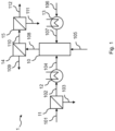
- a preferred embodiment of the method (2) according to the invention is presented, wherein oxygen-enriched gas (206) is fed to an oxy-calciner (10), the oxygen-enriched gas (206) is obtained by flushing the anode (oxy) side (17A) of at least one operating solid oxide electrolysis cell (17) with a feed gas (205) comprising CO 2 , and wherein at least part of the first cathode-side product gas (203) comprising carbon monoxide and/or hydrogen, is supplied to a hydrogen- and/or carbon monoxide-consuming process (18).
- a first anode-side feed gas comprising carbon dioxide (204) is pre-heated using an anode-side preheater (19) and the pre-heated first anode-side feed gas (205) is fed to the anode (oxy) side (17A) of the solid oxide electrolysis cell.
- External voltage is applied to the solid oxide electrolysis cell (17), thereby providing a driving force for the electrochemical reduction of at least part of the carbon dioxide and/or steam in the first cathode-side feed stream (202) into carbon monoxide and/or hydrogen, thereby forming a first cathode-side product gas (203) that is enriched in hydrogen, carbon monoxide or a mixture thereof.
- Part of (not shown) or all of the first cathode-side product gas (203) is supplied to a hydrogen- and/or carbon monoxide-consuming process (18), such as a methanol production process, ammonia production process, a hydrotreating process, a methanation process, a hydrogenation process, a carbonylation process, a hydroformulation (oxo synthesis) process, or an oxidative carbonylation process.
- the externally applied voltage drives an electrochemical oxidation reaction on the anode side (17A) of the solid oxide electrolysis cell, whereby oxygen ions (O 2- ) are converted into molecular oxygen (O 2 ).
- the electrochemically generated O 2 is mixed with the pre-heated first anode-side feed gas comprising carbon dioxide (205), thereby forming a first anode-side product gas, the oxygen-enriched gas (206), with a low nitrogen content.
- the operating temperature of the solid oxide electrolysis cell (17) is generally between 600°C and 1000°C and preferably between 600°C and 900°C 700°C and 850°C. Due to the high operating temperature of the solid oxide electrolysis cell, the oxygen-enriched stream (206) does not need to be heated further before being fed into the oxy-calciner (10) but may be passed through heat exchangers (not shown). It is further understood that other aforementioned streams may be passed through heat exchangers for better thermal integration.
- a stream of fuel (105) is being fed to the oxy-calciner (10) and the stream is optionally preheated (not shown).
- a stream of solid material comprising calcium carbonate (106) is pre-heated (e.g. to around 650°C) using a preheater (13), such as a solid-gas cyclone, and the preheated stream of solid material (107) is fed to the oxy-calciner (10).
- Fuel (105) reacts with the oxygen in the oxygen-enriched stream (206) and the exothermic combustion reaction raises the temperature in the oxy-calciner (10) to around 900°C, which causes the calcium carbonate in the solid material (107) to decompose into calcium oxide and carbon dioxide in the oxy-calciner (10).
- the output stream (108) from the oxy-calciner, comprising calcium oxide, carbon dioxide and steam is fed to a first separator (14), such as a cyclone, where the stream is separated into a stream comprising calcium oxide (109) and a stream comprising carbon dioxide and steam (110).
- the stream (110) is further fed to another separator (15), such as a water knockout vessel, where the stream is separated into a stream comprising H 2 O (111) and a stream comprising carbon dioxide (112).
- An oxy-calciner with a capacity to calcine 300 tonnes of calcium carbonate per hour requires approximately 13 tonnes of methane or natural gas per hour as fuel and approximately 61 tonnes of oxygen-enriched gas per hour as oxidant, assuming the oxygen content in the oxygen-enriched stream (206) is 95 vol%, balance CO 2 .
- the required flow rate of the first anode-side feed stream (204) depends on the desired oxygen-content in the oxygen-enriched stream (206). In order to feed 61 tonnes of an oxygen-enriched gas (206) comprising 95 vol% O 2 in CO 2 to the oxy-calciner, approximately 4 tonnes of CO 2 have to be supplied to the anode side (17A) of the electrolysis unit (17).
- the amount of oxygen produced by the solid oxide electrolysis cell (17) is determined by Faraday's law: for producing 57 tonnes per hour of oxygen, the required electric current through the electrolysis unit is approximately 191 000 000 A.
- Typical electrolysis currents for solid oxide electrolysis cells range from 0.5 A/cm 2 to 1 A/cm 2 .
- the required electrode area for the electrolysis unit (17) under abovementioned conditions ranges therefore between 19100 m 2 and 38200 m 2 .
- Such an electrolysis unit would produce approximately 7 tonnes of hydrogen per hour on the cathode side of the cell, when pure water or steam is used as the first cathode-side feed stream (201) to the cell or approximately 100 tonnes of CO per hour on the cathode side of the cell, when pure CO 2 is used as the first cathode-side feed stream (201) to the cell. Highest system efficiencies are achieved when the electrolysis unit (17) is operated close to the thermoneutral voltage.
- the nitrogen content of the oxygen-enriched gas stream (206) is determined by the nitrogen content in the first anode-side feed gas stream (204). For example, if the first anode-side feed gas stream (204) has a nitrogen content of 1 vol% and the desired oxygen content in the oxygen-enriched stream (206) is 95 vol%, then the resulting nitrogen content in the oxygen-enriched gas stream (206) is approximately 0.05 vol%.
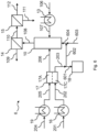
- a preferred embodiment of the method (3) according to the invention is presented, wherein oxygen-enriched gas (312) is fed to an oxy-calciner (10), the oxygen-enriched gas (312) is obtained by flushing the anode (oxy) side (17A) of at least one solid oxide electrolysis cellsolid oxide electrolysis cell (17) with a anode-side feed gas (308,309) comprising CO 2 , and wherein at least part of the first cathode-side product gas (304,305), enriched in carbon monoxide and/or hydrogen, is supplied to a hydrogen- and/or carbon monoxide-consuming process (18), and where part of either or both of the product gas streams (304,310) from the solid oxide electrolysis cellsolid oxide electrolysis cell (17) are recycled back to the cell.
- the preheated first cathode-side feed stream (302) is optionally mixed with a first cathode-side recycle stream (306), thereby obtaining a second cathode-side feed stream (303), which is fed to the cathode side (17C) of at least one solid oxide electrolysis cell (17).
- External voltage is applied to the solid oxide electrolysis cell (17), thereby providing a driving force for the electrochemical reduction of at least part of the carbon dioxide and/or steam in the second cathode-side feed stream (303) into carbon monoxide and/or hydrogen, thereby forming a first cathode-side product gas (304) that is enriched in hydrogen, carbon monoxide or a mixture thereof.
- part of the first cathode-side product gas (304) is recycled back to the electrochemical cell (17) as a first cathode-side recycle stream (306).
- the remainder of the first cathode-side product gas (305) is supplied to a hydrogen- and/or carbon monoxide-consuming process (18).
- the splitting of the first cathode-side product gas (304) into streams (305) and (306) may be carried out in a separation unit, such as a pressure-swing adsorber or a temperature-swing adsorber or a separation membrane. Additional blowers or compressors may be included to increase the pressure of the stream (304).
- a first anode-side feed stream comprising carbon dioxide (307) is pre-heated using an anode-side preheater (19).
- the pre-heated first anode-side feed stream (308) is optionally mixed with a first anode-side recycle stream (311), thereby obtaining a second anode-side feed stream (309), which is fed to the anode side (17C) of at least one solid oxide electrolysis cell (17).
- the externally applied voltage drives an electrochemical oxidation reaction on the anode side (17A) of the solid oxide electrolysis cell, whereby oxygen ions (O 2- ) are converted into molecular oxygen (O 2 ).
- the electrochemically generated O 2 is mixed with the second anode-side feed gas comprising carbon dioxide (309), thereby forming a first anode-side product gas (310) with a low nitrogen content.
- part of the first anode-side product gas (310), enriched in oxygen is recycled back to the electrochemical cell (17) as a first anode-side recycle stream (311).
- the remainder of the first anode-side product gas, the oxygen-enriched gas (312), is Oxy-calciner + SOEC, with CO2 recycle from flue gas to SOEC fed into the oxy-calciner (10).
- the splitting of the first anode-side product gas (310) into streams (311) and (312) may be carried out in a separation unit, such as a pressure-swing adsorber or a temperature-swing adsorber or a separation membrane. Additional blowers or compressors may be included to increase the pressure of the stream (310). Due to the high operating temperature of the solid oxide electrolysis cell, the oxygen-enriched stream (312) does not need to be heated further but may be passed through heat exchangers (not shown). It is further understood that other aforementioned streams may be passed through heat exchangers or additional pre-heaters for better thermal integration.
- FIG. 4 an embodiment not according to the invention is presented, wherein oxygen-enriched gas (312) is fed to an oxyfuel combustion chamber (20), the oxygen-enriched gas (312) is obtained by flushing the anode (oxy) side (17A) of at least one solid oxide electrolysis cell (17) with a anode-side feed gas (308,309) comprising CO 2 , and wherein at least part of the first cathode-side product gas (304,305), enriched in carbon monoxide and/or hydrogen, is supplied to a hydrogen- and/or carbon monoxide-consuming process (18), and where part of either or both of the output gas streams from the solid oxide electrolysis cell (17) are recycled back to the cell as described in Example 3.
- the oxygen content in the first anode-side product gas (310,312) is between 20 vol% and 40 vol%, for example 35 vol% to match the heat capacity of air and to obtain flame temperatures similar to flame temperatures in air-blown kilns.
- the aforementioned streams may be passed through heat exchangers or additional pre-heaters for better thermal integration.
- Suitable oxyfuel combustion chamber designs for the purpose are pulverized fuel kilns or circulating fluidized bed (CFB) kilns.
- a stream of solid fuel (401) comprising e.g. coal, wood or biomass, is optionally pre-heated using a preheater (21), thereby obtaining a pre-heated solid fuel stream (402).
- the pre-heated solid fuel stream (402) is fed to the oxyfuel combustion chamber (20).
- solid fuel (402) reacts with the oxygen in the oxygen-enriched gas stream (312) and the exothermic combustion reaction raises the flame temperature near the burner (1 to 4 meters from the burner) to above 1100°C and up to 1900°C.
- the output stream (403) from the oxyfuel combustion chamber (20), comprising solid combustion residues, carbon dioxide and steam is fed to a first separator (22), such as a cyclone, where the stream is separated into a stream comprising solid combustion residues (404) and a stream comprising carbon dioxide and steam (405).
- the stream (405) is further fed to a second separator (23), such as a water knockout vessel, where the stream is separated into a stream comprising H 2 O (406) and a stream comprising carbon dioxide (407). Further separation steps may be required and are known to those skilled in the art.
- a 0.21 MW pilot-scale coal oxycombustion unit requires a solid fuel (coal) stream (401) of 31 kg per hour and an oxygen-enriched stream (312) of 233 kg per hour, assuming the oxygen-content in the oxygen-enriched stream (312) is 35 vol%, balance CO 2 and an oxygen excess of 5%.
- the output stream (403) from the oxyfuel combustion chamber (20) contains less nitrogen oxides (NO x ) compared to air-blown kilns. NO x concentration is a function of the flame temperature, and thereby increases when oxygen-enriched streams (312) with higher oxygen contents are used.
- the nitrogen content in the solid fuel stream (401,402) also affects NO x concentration in stream (403).
- FIG. 5 another preferred embodiment of the method (5) according to the invention is presented, wherein oxygen-enriched gas (206) is fed to an oxy-calciner (10), the oxygen-enriched gas (206) is obtained by flushing the anode (oxy) side (17A) of at least one solid oxide electrolysis cell (17) with a first anode-side feed gas (205) comprising CO 2 , wherein at least part of the carbon monoxide and/or hydrogen containing gas (203) is supplied to a hydrogen- and/or carbon monoxide-consuming process (18), and wherein a flue gas stream comprising carbon dioxide (503) is recycled, i.e.
- the feed gas streams (201,204) to the electrolysis unit comprise at least part of the flue gas stream comprising carbon dioxide (503).
- the flue gas stream comprising carbon dioxide (501) is split into two equal or non-equal parts, wherein the first part of the stream comprising carbon dioxide (502) is led out of the process, while the second part of the stream comprising carbon dioxide (503) is used to supply the electrolysis stack with feed gas.
- stream (503) is split into two equal or non-equal parts (504,505), wherein stream (504) is optionally mixed with a supplementary cathode-side feed stream (506) comprising water or steam or CO 2 or a mixture thereof, thereby obtaining a first cathode-side feed stream (201).
- Stream (505) is optionally mixed with a supplementary anode-side feed stream (507) comprising CO 2 , thereby obtaining the first anode-side feed gas (204).
- the supplementary gas stream (506) comprises steam and is low in CO 2 content. It is understood that the stream comprising carbon dioxide (503) may be supplied to either or both sides of the solid oxide electrolysis cell (17).
- FIG. 6 another preferred embodiment of the method (6) according to the invention is presented, wherein oxygen-enriched gas (206) is fed to an oxy-calciner (10), the oxygen-enriched gas (206) is obtained by flushing the anode (oxy) side (17A) of at least one solid oxide electrolysis cell (17) with a feed gas (205) comprising CO 2 , and wherein at least part of the first cathode-side product gas (203), comprising carbon monoxide and/or hydrogen, is supplied to a hydrogen- and/or carbon monoxide-consuming process (18), and wherein simultaneously a part of the carbon monoxide and/or hydrogen containing first cathode-side product gas (203) is supplied as fuel stream (602) to the oxy-calciner (10).
- a feed gas (205) comprising CO 2
- the first cathode-side product gas (203) comprising carbon monoxide and/or hydrogen
- the first cathode-side product gas (203) is split into two equal or nont-equal parts (601,602).
- Stream (601) is supplied to a hydrogen- and/or carbon monoxide-consuming process (18), whereas stream (602) is used as fuel in the oxy-calciner (10).
- the stream (602), enriched in hydrogen and/or carbon monoxide may be mixed with additional fuel (603), such as methane, natural gas, hydrogen, carbon monoxide etc, thereby obtaining a combined fuel stream (604) that is fed into the oxy-calciner (10). It is understood that part of streams (203,206) may be recycled back to the corresponding sides of the solid oxide electrolysis cell, as described in Example 3 and 4 and not explicitly shown in Fig. 6 .
- oxygen-enriched gas (703) is fed to an oxyfuel combustion chamber (20), wherein the oxygen-enriched gas (703) is obtained by mixing (in equal or non-equal parts) the following gas streams: a first anode-side product gas, enriched in oxygen (312), obtained by flushing the anode (oxy) side (17A) of at least one solid oxide electrolysis cell (17) with a anode-side feed gas (308,309) comprising CO 2 , and a flue gas stream (701), obtained by splitting the flue gas stream comprising CO 2 (407) in two equal or non-equal parts (701,702).
- a first anode-side product gas, enriched in oxygen (312) obtained by flushing the anode (oxy) side (17A) of at least one solid oxide electrolysis cell (17) with a anode-side feed gas (308,309) comprising CO 2
- a flue gas stream (701) obtained by splitting the flue gas stream comprising CO 2 (407) in two equal or non-equal parts (701,702).
- the stream (702) is led out of the system, while stream (701) is recycled, as explained above.
- the oxygen content in the first anode-side product gas (310,312) is between 90 vol% and 100 vol%, for example 95 vol%, to minimize total gas flow rate though the anode compartment of the solid oxide electrolysis cell.
- the oxygen content in the oxygen-enriched gas (703) is between 20 vol% and 40 vol%, for example 35 vol%, to match the heat capacity of air and to obtain flame temperatures similar to flame temperatures in air-blown kilns.
- Two identical solid oxide electrolysis cell stacks each comprising 75 cells with a total active area of approximately 8250 cm 2 , were operated for 120 hours in electrolysis mode ( Fig. 8 ).
- a first cathode-side feed stream (301) comprising ⁇ 99.9% CO 2 was mixed with a first cathode-side recycle stream (306), comprising CO and CO 2 , thereby obtaining a second cathode-side feed stream (303).
- the second cathode-side feed stream (303) was simultaneously introduced onto the cathode-side compartments of both stacks at a temperature of 800°C ( Fig. 8a ).
- An electrolysis current was passed through both stacks, resulting in a fraction of the CO 2 in the cathode-side feed stream to be electrochemically converted into CO, thereby enriching the first cathode-side product stream (304) exiting the stacks with CO.
- the temperature of the stream (304) exiting the stack was 751-753°C.
- the gas was compressed and fed to a pressure-swing adsorber unit.
- the CO-rich exit stream (305) from the pressure-swing adsorber unit was collected as product to be used in e.g. phosgene plants, while the CO-lean exit stream (306) from the pressure-swing adsorber unit was mixed with the first cathode-side feed stream (301), as described above.
- gaseous O 2 was electrochemically generated on the anode sides of the cells in the stacks, whereby a first anode-side product gas (206), enriched in oxygen, was obtained.
- the first anode-side product gas (206) comprised CO 2 and O 2 and was notably low in nitrogen content. The precise nitrogen content was not measured, but was estimated to be below 50 ppm.
- the temperature of the first anode-side product gas (206) exiting the stacks was 791-793°C during the experiment.
- the stack voltages required to maintain an electrolysis current of approximately 45 A were between 97 V and 103 V ( Fig. 8b ).
- no significant performance degradation was observed while operating the solid oxide electrolysis cells using an anode-side stream comprising ⁇ 99.9% CO 2 .
Landscapes
- Chemical & Material Sciences (AREA)
- Engineering & Computer Science (AREA)
- Materials Engineering (AREA)
- Organic Chemistry (AREA)
- Chemical Kinetics & Catalysis (AREA)
- Electrochemistry (AREA)
- Metallurgy (AREA)
- Inorganic Chemistry (AREA)
- Ceramic Engineering (AREA)
- Sustainable Development (AREA)
- Life Sciences & Earth Sciences (AREA)
- Physics & Mathematics (AREA)
- Thermal Sciences (AREA)
- Structural Engineering (AREA)
- Combustion & Propulsion (AREA)
- Mechanical Engineering (AREA)
- General Engineering & Computer Science (AREA)
- Automation & Control Theory (AREA)
- Electrolytic Production Of Non-Metals, Compounds, Apparatuses Therefor (AREA)
- Oxygen, Ozone, And Oxides In General (AREA)
Claims (16)
- Verfahren zum Zuführen von mit Sauerstoff angereichertem Gas (206, 312) zu einem Sauerstoff verbrauchenden Prozess (10), bei dem es sich um einen Oxy-Kalzinierungsprozess handelt, bei dem mindestens eine sich in Betrieb befindliche Festoxid-Elektrolysezelle mit einer Kathodenseite und einer Anodenseite bereitgestellt wird, unda) ein kathodenseitiger Einspeisegasstrom, der Dampf oder CO2 oder eine Mischung davon (202, 303) umfasst, der Kathodenseite (17C) der mindestens einen Festoxid-Elektrolysezelle (17) zugeführt wird,b) mindestens ein Teil des kathodenseitigen Einspeisegasstroms (202, 303) in der Festoxid-Elektrolysezelle elektrochemisch reduziert wird, wodurch ein kathodenseitiger Produktgasstrom (203, 304) gebildet wird, der mit Wasserstoff, Kohlenmonoxid oder einer Mischung davon angereichert ist,c) mindestens ein Teil des kathodenseitigen Produktgasstroms (203, 304) einem Wasserstoff und/oder Kohlenmonoxid verbrauchenden Prozess (18) zugeführt wird,d) ein anodenseitiger Einspeisegasstrom, der CO2 (205, 309) umfasst, der Anodenseite (17A) der Festoxid-Elektrolysezelle (17) zugeführt wird unde) Sauerstoff auf der Anodenseite der Festoxid-Elektrolysezelle elektrochemisch erzeugt wird, wodurch ein anodenseitiger, mit Sauerstoff angereicherter Produktgasstrom (206, 310) gebildet wird, wobeiein mit Sauerstoff angereichertes Gas, das mindestens einen Teil des mit Sauerstoff angereicherten anodenseitigen Produktgasstroms (206) umfasst, in den Sauerstoff verbrauchenden Prozess eingespeist wird,- das mit Sauerstoff angereicherte Gas einen geringen Stickstoffgehalt aufweist, wobei der Stickstoffgehalt unter 10 Vol% liegt, und- das mit Sauerstoff angereicherte Gas, das die Festoxid-Elektrolysezelle verlässt, eine Temperatur im Bereich zwischen 600 °C und 1000 °C aufweist.
- Verfahren nach Anspruch 1, wobei die Temperatur des mit Sauerstoff angereicherten Gases, das die mindestens eine Festoxid-Elektrolysezelle verlässt, zwischen 600 °C und 900 °C, vorzugsweise zwischen 700 °C und 850 °C ist.
- Verfahren nach Anspruch 1 oder 2, wobei der Wasserstoff oder das Kohlenmonoxid oder die Mischung aus Wasserstoff und Kohlenmonoxid, der/das/die elektrochemisch auf der Kathodenseite der mindestens einen Festoxid-Elektrolysezelle erzeugt wird, und der Sauerstoff, der elektrochemisch auf der Anodenseite der mindestens einen Festoxid-Elektrolysezelle erzeugt wird, in einem Molverhältnis von (H2)+CO):O2 von 2:1 erzeugt werden.
- Verfahren nach einem der vorstehenden Ansprüche, wobei das anodenseitige, mit Sauerstoff angereicherte Produktgas (206, 310) einen Sauerstoffgehalt von 0 < O2 ≤ 100 %, vorzugsweise zwischen 80 % und 100 % und besonders bevorzugt zwischen 95% und 100 % aufweist.
- Verfahren nach einem der vorstehenden Ansprüche, wobei mindestens ein Teil des anodenseitigen Produktgases (206, 310) recycelt und als mindestens ein Teil des anodenseitigen Einspeisegases (205, 309) verwendet wird.
- Verfahren nach einem der vorstehenden Ansprüche, wobei der mindestens eine Teil des kathodenseitigen Produktgases (203, 304) recycelt und als mindestens ein Teil des kathodenseitigen Einspeisestroms (202, 303) verwendet wird.
- Verfahren nach einem der vorstehenden Ansprüche, wobei aus dem Oxy-Kalzinierungsprozess ein Rauchgasstrom erhalten wird, der Kohlendioxid (112, 407, 503) umfasst und recycelt und als mindestens ein Teil des kathodenseitigen Einspeisestroms (202, 303) und/oder des anodenseitigen Einspeisegases (205, 309), das in die Festoxid-Elektrolysezelle eingespeist wird, verwendet wird.
- Verfahren nach einem der vorstehenden Ansprüche, wobei der Wasserstoff und/oder Kohlenmonoxid verbrauchende Prozess (18) Prozesse zur Herstellung von Methanol, Prozesse zur Ammoniakproduktion, Hydrotreating-Prozesse, Methanisierungsprozesse, Hydrierungsprozesse, Carbonylierungsprozesse, Hydroformulierungsprozesse (Oxo-Synthese) oder oxidative Carbonylierungsprozesse umfasst.
- Verfahren nach einem der vorstehenden Ansprüche, wobei der kathodenseitige Einspeisestrom (201, 301, 506) CO2 umfasst und mindestens ein Teil des CO2 im kathodenseitigen Einspeisegasstrom (201,301,506) und/oder im anodenseitigen Einspeisegasstrom (204, 307, 507) aus einem oder mehreren von Folgendem stammt:
Metallurgieprozesse, Zementproduktion, Kohlenstoffabscheidungsprozesse, direkte Luftabscheidungsprozesse und kohlenstoffbasierte Brennstoffverbrennungsprozesse, einschließlich einer Verbrennung nichtfossiler Brennstoffe oder andere Prozesse, bei denen CO2 in einem oder mehreren Strömen erzeugt wird. - Verfahren nach einem der vorstehenden Ansprüche, wobei der Stickstoffgehalt im mit Sauerstoff angereicherten Strom (206, 312) weniger als 1 % beträgt.
- Verfahren nach einem der vorstehenden Ansprüche, wobei der Stickstoffgehalt im mit Sauerstoff angereicherten Strom (206, 312) weniger als 0,1 % beträgt.
- Verfahren nach einem der vorstehenden Ansprüche, wobei die Festoxid-Elektrolysezelle bei thermoneutraler Spannung oder innerhalb von ±0,2 V/Zelle von der thermoneutralen Spannung betrieben wird.
- Anlage, umfassend:eine Festoxid-Elektrolysezelle (17) mit einer Anodenseite (17A) und einer Kathodenseite (17C);eine Sauerstoff verbrauchende Einheit, die eine Oxy-Kalzinierungseinheit (10) ist; undeine Wasserstoff und/oder Kohlenmonoxid verbrauchende Einheit (18), wobei die Anodenseite der Zelle (17A) in Fluidverbindung mit der Sauerstoff verbrauchenden Einheit steht und die Kathodenseite der Zelle in Fluidverbindung mit der Wasserstoff und/oder Kohlenmonoxid verbrauchenden Einheit (18) steht, und wobei die Anlage konfiguriert ist, das Verfahren nach einem der vorstehenden Ansprüche durchzuführen.
- Anlage nach Anspruch 13, wobei die Sauerstoff verbrauchende Einheit und die Wasserstoff und/oder Kohlenmonoxid verbrauchende Einheit ein und dieselbe Oxy-Kalzinierungseinheit ist.
- Anlage nach Anspruch 13 oder 14, wobei die Anlage Steuermittel umfasst, die konfiguriert sind, den Fluss von der Anodenseite der Festoxid-Elektrolysezelle zu der Sauerstoff verbrauchenden Einheit zu steuern.
- Anlage nach einem der Ansprüche 13 bis 15, wobei die Anlage Steuermittel umfasst, die konfiguriert sind, den Fluss von der Kathodenseite der Festoxid-Elektrolysezelle zu der Wasserstoff und/oder Kohlenmonoxid verbrauchenden Einheit zu steuern.
Applications Claiming Priority (2)
| Application Number | Priority Date | Filing Date | Title |
|---|---|---|---|
| DKPA202000154 | 2020-02-06 | ||
| PCT/EP2021/052839 WO2021156457A1 (en) | 2020-02-06 | 2021-02-05 | A method for supplying oxygen-enriched gas to an oxygen-consuming process |
Publications (3)
| Publication Number | Publication Date |
|---|---|
| EP4100559A1 EP4100559A1 (de) | 2022-12-14 |
| EP4100559C0 EP4100559C0 (de) | 2024-01-10 |
| EP4100559B1 true EP4100559B1 (de) | 2024-01-10 |
Family
ID=74561901
Family Applications (1)
| Application Number | Title | Priority Date | Filing Date |
|---|---|---|---|
| EP21703908.0A Active EP4100559B1 (de) | 2020-02-06 | 2021-02-05 | Verfahren zur zuführung eines mit sauerstoff angereicherten gases zu einem sauerstoffverbrauchenden prozesses |
Country Status (6)
| Country | Link |
|---|---|
| US (1) | US12331413B2 (de) |
| EP (1) | EP4100559B1 (de) |
| JP (1) | JP7769617B2 (de) |
| CN (1) | CN115087762B (de) |
| AU (1) | AU2021216120B2 (de) |
| WO (1) | WO2021156457A1 (de) |
Families Citing this family (10)
| Publication number | Priority date | Publication date | Assignee | Title |
|---|---|---|---|---|
| JP7644500B2 (ja) | 2019-04-29 | 2025-03-12 | カーボンクエスト, インコーポレイテッド | 建物排出物処理および/または隔離システムならびに方法 |
| US12367498B2 (en) | 2021-10-11 | 2025-07-22 | Carbonquest, Inc. | Carbon management systems and method for management of carbon use and/or production in buildings |
| CN114151785B (zh) * | 2021-12-03 | 2024-04-05 | 上海源晗能源技术有限公司 | 燃煤锅炉碳基富氧燃烧及co2捕集与利用工艺 |
| WO2023147123A1 (en) * | 2022-01-31 | 2023-08-03 | Carbonquest, Inc. | SYSTEMS AND METHODS FOR GENERATING eFUELS AND PLATFORM CHEMICALS FROM CARBON BASED FUEL COMBUSTION SOURCES |
| JP7777034B2 (ja) * | 2022-04-26 | 2025-11-27 | 株式会社日立製作所 | 炭化水素製造システム |
| CN120035694A (zh) | 2022-12-21 | 2025-05-23 | 托普索公司 | 在化工设备中使用富co2气体作为吹扫气体 |
| CN116592350B (zh) * | 2023-04-26 | 2025-08-22 | 西安热工研究院有限公司 | 氨燃烧系统 |
| US20240400908A1 (en) | 2023-05-30 | 2024-12-05 | Arcadia eFuels US Inc. | Production of synthetic hydrocarbons |
| US20250073695A1 (en) * | 2023-09-06 | 2025-03-06 | Chevron U.S.A. Inc. | Methods and systems for utilizing carbon dioxide in flue gas |
| WO2025162555A1 (en) * | 2024-01-30 | 2025-08-07 | L'air Liquide, Societe Anonyme Pour L'etude Et L'exploitation Des Procedes Georges Claude | Integration of solid oxide electrolysis cells (soec) and oxygen purificator to enhance high temperature processes |
Family Cites Families (28)
| Publication number | Priority date | Publication date | Assignee | Title |
|---|---|---|---|---|
| JPS5792514A (en) * | 1980-11-29 | 1982-06-09 | Nippon Steel Corp | Method for concentrating carbon dioxide in exhaust gas of limestone calcination furnace |
| WO2007014127A2 (en) | 2005-07-25 | 2007-02-01 | Ion America Corporation | Fuel cell system with partial recycling of anode exhaust |
| US7951283B2 (en) * | 2006-07-31 | 2011-05-31 | Battelle Energy Alliance, Llc | High temperature electrolysis for syngas production |
| CA2860684C (en) | 2006-09-25 | 2015-12-01 | The Ohio State University | High purity, high pressure hydrogen production with in-situ co2 and sulfur capture in a single stage reactor |
| US8366902B2 (en) * | 2008-03-24 | 2013-02-05 | Battelle Energy Alliance, Llc | Methods and systems for producing syngas |
| DE102008034420A1 (de) * | 2008-07-23 | 2010-01-28 | Linde Ag | Verfahren und Vorrichtung zum Betreiben einer elektrochemischen Stromquelle |
| AU2010352713B2 (en) | 2010-05-05 | 2014-07-31 | Haldor Topsoe A/S | Process for operating a high temperature fuel cell stack |
| US20140110270A1 (en) | 2011-05-26 | 2014-04-24 | Topsøe Fuel Cell A/S | Electrical anode reduction of solid oxide fuel cell |
| TWI500820B (zh) | 2012-03-05 | 2015-09-21 | 哈爾德杜薩公司 | 製造高純度一氧化碳之設備 |
| US9664385B2 (en) | 2012-09-17 | 2017-05-30 | Phillips 66 Company | Process for enabling carbon-capture from existing combustion processes |
| CN105102684B (zh) | 2013-01-25 | 2017-09-08 | 托普索公司 | 电解器系统的监测、保护和安全关闭的方法 |
| US8728428B1 (en) | 2013-03-13 | 2014-05-20 | Carbon Engineering Limited Partnership | Recovering a caustic solution via calcium carbonate crystal aggregates |
| DK2989233T3 (da) | 2013-03-26 | 2020-10-12 | Haldor Topsoe As | Fremgangsmåde til fremstilling af carbonmonoxid (CO) ud fra carbondioxid (CO2) i en fastoxidelektrolysecelle |
| EP2933357A1 (de) * | 2014-04-14 | 2015-10-21 | Haldor Topsøe A/S | Verbesserung der Lebensdauer eines SOEC-Systems durch Steuerung der Einlassgaszusammensetzung |
| US9637393B2 (en) | 2014-05-19 | 2017-05-02 | Carbon Engineering Limited Partnership | Recovering a caustic solution via calcium carbonate crystal aggregates |
| KR20160036881A (ko) | 2014-09-26 | 2016-04-05 | 한국전력공사 | 이산화탄소 재활용 방법 및 이를 이용한 이산화탄소 재활용 장치 |
| EP3031956B1 (de) * | 2014-12-10 | 2017-07-26 | Haldor Topsoe As | Verfahren zur Herstellung von ultrahochreinem Kohlenmonoxid |
| WO2017116307A1 (en) * | 2015-12-28 | 2017-07-06 | Nanyang Technological University | A promising co- electrolyzer for the direct use of flue gas from power plant |
| DE112017005364T5 (de) * | 2016-10-24 | 2019-07-18 | Precision Combustion, Inc. | Regenerativer festoxidstapel |
| BR112019013078B1 (pt) * | 2016-12-23 | 2024-01-02 | Carbon Engineering Ltd | Método e sistema para sintetizar combustível a partir de fonte de dióxido de carbono diluído |
| WO2018148490A1 (en) * | 2017-02-09 | 2018-08-16 | Battelle Energy Alliance, Llc | Methods and systems for syngas production and for efficient, flexible energy generation |
| DE102017005680A1 (de) | 2017-06-14 | 2018-12-20 | Linde Aktiengesellschaft | Verfahren und Anlage zur Herstellung eines Kohlenmonoxid enthaltenden Gasprodukts |
| CN111683731B (zh) | 2018-02-12 | 2022-09-02 | 朗泽科技有限公司 | 用于提高碳转化效率的工艺 |
| JP7374120B2 (ja) | 2018-04-13 | 2023-11-06 | トプソー・アクチエゼルスカベット | 合成反応に使用するための一酸化炭素および二酸化炭素を含むガス混合物を生成するための方法 |
| WO2020011748A1 (en) | 2018-07-12 | 2020-01-16 | Haldor Topsøe A/S | Expander for soec applications |
| EP4123056B1 (de) * | 2021-07-20 | 2024-01-17 | Topsoe A/S | Verfahren zum transienten betrieb eines festoxid-elektrolysezellenstapels |
| KR20230111592A (ko) * | 2022-01-18 | 2023-07-25 | 블룸 에너지 코퍼레이션 | Soec 시스템의 대기 작동을 위한 압축기 통합 및 안전한 작동 시작 |
| CN115466986B (zh) * | 2022-09-28 | 2023-05-12 | 西南石油大学 | 一种用于废水电解制氢的电极及其制备方法和应用 |
-
2021
- 2021-02-05 AU AU2021216120A patent/AU2021216120B2/en active Active
- 2021-02-05 CN CN202180012763.6A patent/CN115087762B/zh active Active
- 2021-02-05 US US17/795,763 patent/US12331413B2/en active Active
- 2021-02-05 WO PCT/EP2021/052839 patent/WO2021156457A1/en not_active Ceased
- 2021-02-05 JP JP2022547867A patent/JP7769617B2/ja active Active
- 2021-02-05 EP EP21703908.0A patent/EP4100559B1/de active Active
Also Published As
| Publication number | Publication date |
|---|---|
| CA3165500A1 (en) | 2021-08-12 |
| JP7769617B2 (ja) | 2025-11-13 |
| EP4100559C0 (de) | 2024-01-10 |
| CN115087762A (zh) | 2022-09-20 |
| AU2021216120B2 (en) | 2026-01-29 |
| KR20220140548A (ko) | 2022-10-18 |
| JP2023512779A (ja) | 2023-03-29 |
| AU2021216120A1 (en) | 2022-08-18 |
| WO2021156457A1 (en) | 2021-08-12 |
| US12331413B2 (en) | 2025-06-17 |
| CN115087762B (zh) | 2024-10-01 |
| EP4100559A1 (de) | 2022-12-14 |
| US20230069515A1 (en) | 2023-03-02 |
Similar Documents
| Publication | Publication Date | Title |
|---|---|---|
| EP4100559B1 (de) | Verfahren zur zuführung eines mit sauerstoff angereicherten gases zu einem sauerstoffverbrauchenden prozesses | |
| EP2969999B1 (de) | Integration von schmelzkarbonat-brennstoffzellen in die zementverarbeitung | |
| AU2014235219B2 (en) | Integrated power generation using molten carbonate fuel cells | |
| CA3165500C (en) | A method for supplying oxygen-enriched gas to an oxygen-consuming process | |
| KR102955822B1 (ko) | 산소-소모 과정에 산소-부화 가스를 공급하는 방법 |
Legal Events
| Date | Code | Title | Description |
|---|---|---|---|
| STAA | Information on the status of an ep patent application or granted ep patent |
Free format text: STATUS: UNKNOWN |
|
| STAA | Information on the status of an ep patent application or granted ep patent |
Free format text: STATUS: THE INTERNATIONAL PUBLICATION HAS BEEN MADE |
|
| PUAI | Public reference made under article 153(3) epc to a published international application that has entered the european phase |
Free format text: ORIGINAL CODE: 0009012 |
|
| STAA | Information on the status of an ep patent application or granted ep patent |
Free format text: STATUS: REQUEST FOR EXAMINATION WAS MADE |
|
| 17P | Request for examination filed |
Effective date: 20220711 |
|
| AK | Designated contracting states |
Kind code of ref document: A1 Designated state(s): AL AT BE BG CH CY CZ DE DK EE ES FI FR GB GR HR HU IE IS IT LI LT LU LV MC MK MT NL NO PL PT RO RS SE SI SK SM TR |
|
| DAV | Request for validation of the european patent (deleted) | ||
| DAX | Request for extension of the european patent (deleted) | ||
| RIC1 | Information provided on ipc code assigned before grant |
Ipc: C04B 2/10 20060101ALI20230908BHEP Ipc: F23L 7/00 20060101ALI20230908BHEP Ipc: C04B 7/43 20060101ALI20230908BHEP Ipc: C25B 15/08 20060101ALI20230908BHEP Ipc: C25B 1/23 20210101ALI20230908BHEP Ipc: C25B 1/042 20210101ALI20230908BHEP Ipc: C25B 1/02 20060101AFI20230908BHEP |
|
| GRAP | Despatch of communication of intention to grant a patent |
Free format text: ORIGINAL CODE: EPIDOSNIGR1 |
|
| STAA | Information on the status of an ep patent application or granted ep patent |
Free format text: STATUS: GRANT OF PATENT IS INTENDED |
|
| INTG | Intention to grant announced |
Effective date: 20231027 |
|
| GRAS | Grant fee paid |
Free format text: ORIGINAL CODE: EPIDOSNIGR3 |
|
| GRAA | (expected) grant |
Free format text: ORIGINAL CODE: 0009210 |
|
| STAA | Information on the status of an ep patent application or granted ep patent |
Free format text: STATUS: THE PATENT HAS BEEN GRANTED |
|
| AK | Designated contracting states |
Kind code of ref document: B1 Designated state(s): AL AT BE BG CH CY CZ DE DK EE ES FI FR GB GR HR HU IE IS IT LI LT LU LV MC MK MT NL NO PL PT RO RS SE SI SK SM TR |
|
| REG | Reference to a national code |
Ref country code: GB Ref legal event code: FG4D |
|
| REG | Reference to a national code |
Ref country code: CH Ref legal event code: EP |
|
| REG | Reference to a national code |
Ref country code: DE Ref legal event code: R096 Ref document number: 602021008530 Country of ref document: DE |
|
| REG | Reference to a national code |
Ref country code: IE Ref legal event code: FG4D |
|
| U01 | Request for unitary effect filed |
Effective date: 20240208 |
|
| U07 | Unitary effect registered |
Designated state(s): AT BE BG DE DK EE FI FR IT LT LU LV MT NL PT SE SI Effective date: 20240216 |
|
| U20 | Renewal fee for the european patent with unitary effect paid |
Year of fee payment: 4 Effective date: 20240226 |
|
| PG25 | Lapsed in a contracting state [announced via postgrant information from national office to epo] |
Ref country code: IS Free format text: LAPSE BECAUSE OF FAILURE TO SUBMIT A TRANSLATION OF THE DESCRIPTION OR TO PAY THE FEE WITHIN THE PRESCRIBED TIME-LIMIT Effective date: 20240510 |
|
| PG25 | Lapsed in a contracting state [announced via postgrant information from national office to epo] |
Ref country code: GR Free format text: LAPSE BECAUSE OF FAILURE TO SUBMIT A TRANSLATION OF THE DESCRIPTION OR TO PAY THE FEE WITHIN THE PRESCRIBED TIME-LIMIT Effective date: 20240411 |
|
| PG25 | Lapsed in a contracting state [announced via postgrant information from national office to epo] |
Ref country code: RS Free format text: LAPSE BECAUSE OF FAILURE TO SUBMIT A TRANSLATION OF THE DESCRIPTION OR TO PAY THE FEE WITHIN THE PRESCRIBED TIME-LIMIT Effective date: 20240410 Ref country code: HR Free format text: LAPSE BECAUSE OF FAILURE TO SUBMIT A TRANSLATION OF THE DESCRIPTION OR TO PAY THE FEE WITHIN THE PRESCRIBED TIME-LIMIT Effective date: 20240110 |
|
| PG25 | Lapsed in a contracting state [announced via postgrant information from national office to epo] |
Ref country code: ES Free format text: LAPSE BECAUSE OF FAILURE TO SUBMIT A TRANSLATION OF THE DESCRIPTION OR TO PAY THE FEE WITHIN THE PRESCRIBED TIME-LIMIT Effective date: 20240110 |
|
| PG25 | Lapsed in a contracting state [announced via postgrant information from national office to epo] |
Ref country code: RS Free format text: LAPSE BECAUSE OF FAILURE TO SUBMIT A TRANSLATION OF THE DESCRIPTION OR TO PAY THE FEE WITHIN THE PRESCRIBED TIME-LIMIT Effective date: 20240410 Ref country code: NO Free format text: LAPSE BECAUSE OF FAILURE TO SUBMIT A TRANSLATION OF THE DESCRIPTION OR TO PAY THE FEE WITHIN THE PRESCRIBED TIME-LIMIT Effective date: 20240410 Ref country code: IS Free format text: LAPSE BECAUSE OF FAILURE TO SUBMIT A TRANSLATION OF THE DESCRIPTION OR TO PAY THE FEE WITHIN THE PRESCRIBED TIME-LIMIT Effective date: 20240510 Ref country code: HR Free format text: LAPSE BECAUSE OF FAILURE TO SUBMIT A TRANSLATION OF THE DESCRIPTION OR TO PAY THE FEE WITHIN THE PRESCRIBED TIME-LIMIT Effective date: 20240110 Ref country code: GR Free format text: LAPSE BECAUSE OF FAILURE TO SUBMIT A TRANSLATION OF THE DESCRIPTION OR TO PAY THE FEE WITHIN THE PRESCRIBED TIME-LIMIT Effective date: 20240411 Ref country code: ES Free format text: LAPSE BECAUSE OF FAILURE TO SUBMIT A TRANSLATION OF THE DESCRIPTION OR TO PAY THE FEE WITHIN THE PRESCRIBED TIME-LIMIT Effective date: 20240110 |
|
| PG25 | Lapsed in a contracting state [announced via postgrant information from national office to epo] |
Ref country code: PL Free format text: LAPSE BECAUSE OF FAILURE TO SUBMIT A TRANSLATION OF THE DESCRIPTION OR TO PAY THE FEE WITHIN THE PRESCRIBED TIME-LIMIT Effective date: 20240110 |
|
| PG25 | Lapsed in a contracting state [announced via postgrant information from national office to epo] |
Ref country code: PL Free format text: LAPSE BECAUSE OF FAILURE TO SUBMIT A TRANSLATION OF THE DESCRIPTION OR TO PAY THE FEE WITHIN THE PRESCRIBED TIME-LIMIT Effective date: 20240110 |
|
| REG | Reference to a national code |
Ref country code: DE Ref legal event code: R097 Ref document number: 602021008530 Country of ref document: DE |
|
| PG25 | Lapsed in a contracting state [announced via postgrant information from national office to epo] |
Ref country code: SM Free format text: LAPSE BECAUSE OF FAILURE TO SUBMIT A TRANSLATION OF THE DESCRIPTION OR TO PAY THE FEE WITHIN THE PRESCRIBED TIME-LIMIT Effective date: 20240110 |
|
| PG25 | Lapsed in a contracting state [announced via postgrant information from national office to epo] |
Ref country code: CZ Free format text: LAPSE BECAUSE OF FAILURE TO SUBMIT A TRANSLATION OF THE DESCRIPTION OR TO PAY THE FEE WITHIN THE PRESCRIBED TIME-LIMIT Effective date: 20240110 |
|
| PG25 | Lapsed in a contracting state [announced via postgrant information from national office to epo] |
Ref country code: SK Free format text: LAPSE BECAUSE OF FAILURE TO SUBMIT A TRANSLATION OF THE DESCRIPTION OR TO PAY THE FEE WITHIN THE PRESCRIBED TIME-LIMIT Effective date: 20240110 |
|
| PG25 | Lapsed in a contracting state [announced via postgrant information from national office to epo] |
Ref country code: SM Free format text: LAPSE BECAUSE OF FAILURE TO SUBMIT A TRANSLATION OF THE DESCRIPTION OR TO PAY THE FEE WITHIN THE PRESCRIBED TIME-LIMIT Effective date: 20240110 Ref country code: SK Free format text: LAPSE BECAUSE OF FAILURE TO SUBMIT A TRANSLATION OF THE DESCRIPTION OR TO PAY THE FEE WITHIN THE PRESCRIBED TIME-LIMIT Effective date: 20240110 Ref country code: RO Free format text: LAPSE BECAUSE OF FAILURE TO SUBMIT A TRANSLATION OF THE DESCRIPTION OR TO PAY THE FEE WITHIN THE PRESCRIBED TIME-LIMIT Effective date: 20240110 Ref country code: CZ Free format text: LAPSE BECAUSE OF FAILURE TO SUBMIT A TRANSLATION OF THE DESCRIPTION OR TO PAY THE FEE WITHIN THE PRESCRIBED TIME-LIMIT Effective date: 20240110 |
|
| PG25 | Lapsed in a contracting state [announced via postgrant information from national office to epo] |
Ref country code: MC Free format text: LAPSE BECAUSE OF FAILURE TO SUBMIT A TRANSLATION OF THE DESCRIPTION OR TO PAY THE FEE WITHIN THE PRESCRIBED TIME-LIMIT Effective date: 20240110 |
|
| PLBE | No opposition filed within time limit |
Free format text: ORIGINAL CODE: 0009261 |
|
| STAA | Information on the status of an ep patent application or granted ep patent |
Free format text: STATUS: NO OPPOSITION FILED WITHIN TIME LIMIT |
|
| PG25 | Lapsed in a contracting state [announced via postgrant information from national office to epo] |
Ref country code: MC Free format text: LAPSE BECAUSE OF FAILURE TO SUBMIT A TRANSLATION OF THE DESCRIPTION OR TO PAY THE FEE WITHIN THE PRESCRIBED TIME-LIMIT Effective date: 20240110 |
|
| 26N | No opposition filed |
Effective date: 20241011 |
|
| PG25 | Lapsed in a contracting state [announced via postgrant information from national office to epo] |
Ref country code: IE Free format text: LAPSE BECAUSE OF NON-PAYMENT OF DUE FEES Effective date: 20240205 |
|
| PG25 | Lapsed in a contracting state [announced via postgrant information from national office to epo] |
Ref country code: IE Free format text: LAPSE BECAUSE OF NON-PAYMENT OF DUE FEES Effective date: 20240205 |
|
| U20 | Renewal fee for the european patent with unitary effect paid |
Year of fee payment: 5 Effective date: 20250224 |
|
| PGFP | Annual fee paid to national office [announced via postgrant information from national office to epo] |
Ref country code: CH Payment date: 20250301 Year of fee payment: 5 |
|
| PG25 | Lapsed in a contracting state [announced via postgrant information from national office to epo] |
Ref country code: CY Free format text: LAPSE BECAUSE OF FAILURE TO SUBMIT A TRANSLATION OF THE DESCRIPTION OR TO PAY THE FEE WITHIN THE PRESCRIBED TIME-LIMIT; INVALID AB INITIO Effective date: 20210205 |
|
| PG25 | Lapsed in a contracting state [announced via postgrant information from national office to epo] |
Ref country code: HU Free format text: LAPSE BECAUSE OF FAILURE TO SUBMIT A TRANSLATION OF THE DESCRIPTION OR TO PAY THE FEE WITHIN THE PRESCRIBED TIME-LIMIT; INVALID AB INITIO Effective date: 20210205 |
|
| PG25 | Lapsed in a contracting state [announced via postgrant information from national office to epo] |
Ref country code: TR Free format text: LAPSE BECAUSE OF FAILURE TO SUBMIT A TRANSLATION OF THE DESCRIPTION OR TO PAY THE FEE WITHIN THE PRESCRIBED TIME-LIMIT Effective date: 20240110 |
|
| REG | Reference to a national code |
Ref country code: CH Ref legal event code: U11 Free format text: ST27 STATUS EVENT CODE: U-0-0-U10-U11 (AS PROVIDED BY THE NATIONAL OFFICE) Effective date: 20260301 |
|
| U20 | Renewal fee for the european patent with unitary effect paid |
Year of fee payment: 6 Effective date: 20260224 |
|
| PGFP | Annual fee paid to national office [announced via postgrant information from national office to epo] |
Ref country code: GB Payment date: 20260223 Year of fee payment: 6 |