EP4100328B1 - Procedure for the selective management of the waste of an automatic machine for manufacturing or packing consumer articles - Google Patents
Procedure for the selective management of the waste of an automatic machine for manufacturing or packing consumer articles Download PDFInfo
- Publication number
- EP4100328B1 EP4100328B1 EP21709093.5A EP21709093A EP4100328B1 EP 4100328 B1 EP4100328 B1 EP 4100328B1 EP 21709093 A EP21709093 A EP 21709093A EP 4100328 B1 EP4100328 B1 EP 4100328B1
- Authority
- EP
- European Patent Office
- Prior art keywords
- component
- motion law
- article
- processed
- defective
- Prior art date
- Legal status (The legal status is an assumption and is not a legal conclusion. Google has not performed a legal analysis and makes no representation as to the accuracy of the status listed.)
- Active
Links
Images


Classifications
-
- B—PERFORMING OPERATIONS; TRANSPORTING
- B65—CONVEYING; PACKING; STORING; HANDLING THIN OR FILAMENTARY MATERIAL
- B65B—MACHINES, APPARATUS OR DEVICES FOR, OR METHODS OF, PACKAGING ARTICLES OR MATERIALS; UNPACKING
- B65B19/00—Packaging rod-shaped or tubular articles susceptible to damage by abrasion or pressure, e.g. cigarettes, cigars, macaroni, spaghetti, drinking straws or welding electrodes
- B65B19/02—Packaging cigarettes
- B65B19/22—Wrapping the cigarettes; Packaging the cigarettes in containers formed by folding wrapping material around formers
- B65B19/223—Wrapping the cigarettes; Packaging the cigarettes in containers formed by folding wrapping material around formers in a curved path; in a combination of straight and curved paths, e.g. on rotary tables or other endless conveyors
-
- B—PERFORMING OPERATIONS; TRANSPORTING
- B65—CONVEYING; PACKING; STORING; HANDLING THIN OR FILAMENTARY MATERIAL
- B65B—MACHINES, APPARATUS OR DEVICES FOR, OR METHODS OF, PACKAGING ARTICLES OR MATERIALS; UNPACKING
- B65B57/00—Automatic control, checking, warning, or safety devices
- B65B57/10—Automatic control, checking, warning, or safety devices responsive to absence, presence, abnormal feed, or misplacement of articles or materials to be packaged
- B65B57/14—Automatic control, checking, warning, or safety devices responsive to absence, presence, abnormal feed, or misplacement of articles or materials to be packaged and operating to control, or stop, the feed of articles or material to be packaged
Definitions
- the present invention relates to a procedure for the selective management of the waste of an automatic machine for manufacturing or packing consumer articles.
- the present invention is advantageously but not exclusively applied in the selective management of the waste of an automatic packaging machine that manufactures cigarette packs, to which the following disclosure will explicitly refer without thereby losing generality.
- Document DE 36 39 972 describes a process and a device for separating out from a material web material web sections which are unusable as a result of defects.
- a processing station for example a packaging machine for cigarettes, is also disclosed, machine that is fed intermittently with material web sections of defined length which are cut off from the material web by means of a cutting device after each take-off cycle.
- An automatic packaging machine for cigarettes usually comprises a plurality of actuators which act on the articles in order to modify the shape, the structure or the position thereof and each actuator can assume a plurality of different positions.
- some actuators are used for conveying semi-finished articles through a plurality of processing stations.
- Such conveying systems in the majority of cases, are continuous systems, i.e. systems which move at a constant speed or according to periodic motion laws so as to respect predetermined concurrences between the article, the components to be added to the article in order to complete it and the processing operations to be carried out.
- the processing stations in turn comprise other actuators designed to feed the aforementioned components to be added to the semi-finished articles (for example a wrapping, a collar, a blank, an absorbent layer, etc.) and/or to process the articles.
- the environmental issue relating to industrial waste has become increasingly widespread.
- such issue falls within the interests of the manufacturer, as the reduction in waste generates (unless a machine stoppage of excessive duration) a considerable saving in raw materials, i.e. in the components to be processed and combined for forming a consumer article.
- the conveying system 4 comprises a belt 5 configured to receive some semi-finished articles 3 and transport them towards a processing station WS.
- the component 6 can be any type of element to be added to the article 3 such as, for example, a collar, a glue, a support, a fastening element, a label, a blank, an absorbent sheet, an elastic, a foodstuff, etc.
- reference numeral 3 will indicate the consumer articles in general and reference numeral 3' will indicate the consumer article being processed.
- reference numeral 6 will indicate the components in general, reference numeral 6' will indicate the defective components and reference numeral 6" will indicate the new components, succeeding the defective components 6'.
- the conveying system 4 also comprises one or more pushers 7.
- the pushers 7 are set in motion by actuators 13 independent of one another and by the belt 5.
- the pushers 7 are set in motion by a single actuating system that is independent of the belt 5.
- the pushers 7 are integral with the conveyor belt 5.
- the automatic machine 1 comprises at least one store (8) containing one or more components 6.
- the component 6 is a planar element, in particular a strip, a wrapping or a blank.
- the component 6 is obtained from a seamless strip, which is fed, cut and possibly rejected along a feeding path FP.
- the component 6 is a continuous strip of wrapping material and the store 8 is thus a reel C.
- the store 8 comprises a plurality of separate (for example collars or blanks) and stored (for example in piles) components.
- the part 2 of the automatic machine 1 further comprises a feeding system 9 configured to feed at least one component 6 from the respective store 8 towards the conveying path CP and along the feeding path FP and according to a second periodic motion law, in particular different from the first periodic motion law which governs the movement of the articles 3.
- the part 2 further comprises a wheel 10 mounted rotatable around a central rotation axis A and provided with seats 11 (in particular pockets) adapted to accommodate the semi-finished articles 3 (the cigarette packs) and (at least) one pusher 7 adapted to push the semi-finished articles 3 into the seats 11 of the movable wheel 10.
- the article 3 being processed i.e. the one inside the work station WS
- the actuators that set in motion the conveying device 4 (and/or the pushers 7) and/or the feeding system 9 comprise electric motors (in particular of brushless type) which are independent of one another.
- the actuators also comprise types of actuation different from the electric motors (for example pneumatic or hydraulic cylinders, electrically actuated cylinders, etc.).
- a first actuator 12 is coupled to the wheel 10 so as to control the rotation of the wheel 10 around the rotation axis A and it is provided with a rotating electric motor (for example of brushless type) which sets the wheel 10 into rotation through the interposition of a reducer (not illustrated);
- a second actuator 13 is coupled to the pusher 7 to control the linear movement of the pusher 7 along a direction D and for a predefined stroke and it is provided with a rotating electric motor (for example of brushless type) and with a reducer which transforms the circular movement into a linear movement (both not illustrated); and, in particular, a third actuator 14 connected to the store 8 and configured to feed the components 6 along the feeding path FP (obviously, the actuator 14 can be any other type of actuator comprising, for example, articulated quadrilaterals, robots, gripping and laying elements, etc.).
- the machine 1 further comprises a control system 15 configured to detect, during the feeding of the components 6, the quality and/or the position and/or the orientation of at least one component 6 so as to establish whether the component is usable or defective.
- a component 6 can be considered defective if it has wrinkles, creases, holes, tears, stains, non-constant thickness, unsuitable dampness, wrong position, incorrect inclination, etc.
- a component is to be considered suitable if it respects all the minimum specifications of quality and/or orientation and/or position.
- the control system 15 is a camera 16, which, for each component 6 passing in front of it, performs a scan (i.e. a photo) so as to determine the quality, the orientation and the position thereof and define whether it is defective or suitable.
- the camera 16 is comprised in a viewing system (in turn comprised in the control system 15) and in a processing system of the images of a known type and not illustrated to a greater extent.
- control system 15 is any type of sensor capable of establishing the quality and/or the position and/or the orientation of a product (for example, ultrasound sensors, capacitive sensors, microwave sensors, photoelectric cells, etc.).
- the automatic machine 1 further comprises a control unit 17 (schematically illustrated in Figure 1 ) configured to control at least the conveying system 4 (by means of the actuator 13) and feeding system 9 (by means of the actuator 14).
- the control unit 17 also controls the wheel 10 (by means of the actuator 12) and, in particular, all the actuators of the part 2 of the automatic machine 1.
- the control unit 17 is the processor of an industrial control unit or an industrial PC.
- control unit 17 is configured to control, in case the component 6' fed is defective, the conveying system 4 according to a first modified motion law, which is different from the first periodic motion law, so as to convey the article 3' being processed.
- control unit 17 is configured to control the feeding system 9 according to a second modified motion law, which is different from the second periodic motion law, so as to feed the new component 6" replacing the defective component 6'.
- the article 3' in the processing step slows down and/or the (usable) component 6" succeeding the defective component 6' accelerates so as to give the feeding system 9 the time necessary to position the succeeding component 6" in the work station WS before the article 3' goes through the feeding path and pushes it into the seat 11.
- the defective component 6' is previously conveyed towards a waste zone WZ (for example a container).
- control unit 17 is configured to process, in case a component 6' fed is defective (as illustrated in the non-limiting embodiment of Figure 3 ), the first and/or the second modified motion law, which comprise respectively (at least) a deceleration (at least) of the article 3' being processed and/or an acceleration of the new component 6".
- the first and/or the second modified motion law which comprise respectively (at least) a deceleration (at least) of the article 3' being processed and/or an acceleration of the new component 6".
- the part 2 of the automatic machine 1 comprises a separation device 18 that separates the components 6, 6', 6", in particular a cutting device 19 that cuts the components 6, 6', 6", which is provided, more precisely, with a knife and with a counter-knife.
- a procedure is provided for the selective management of the waste of at least a part of an automatic machine for manufacturing or packing consumer articles.
- the procedure comprises at least a step of conveying, according to the first periodic motion law, the plurality of semi-finished articles 3 along the conveying path CP through (at least) the work station (WS), where (at least) the component 6, 6" is added to an article 3' being processed.
- the procedure comprises the further step, in particular at least partially simultaneous with the conveying step, of feeding each component 6, 6', 6", according to a second periodic motion law, from the respective store 8 (in the non-limiting embodiment of Figures 2 and 3 , from the reel C) towards the conveying path CP and along the feeding path FP.
- the procedure comprises a step of checking, in a control area IA and during the step of feeding the component 6, 6' (i.e. before said component 6, 6' reaches the conveying path CP and not compulsorily during the movement of the component 6, 6' along the feeding path FP) the quality and/or the position and/or the orientation of the component and establishing whether the component is usable or defective.
- the control system 15 (more precisely, the camera 16) scans the component 6, 6', 6" directed towards the conveying path CP (and towards the article 3' being processed), determines whether the component 6, 6', 6" is suitable or defective (i.e. to be rejected) and communicates this to the control unit 17, for the possible variation of the motion laws of the component 3' being processed (i.e. the one which should have received the defective component 6', Figure 3 ) and/or of the succeeding component 6".
- the procedure also comprises a replacement step, during which the defective component 6' is conveyed from the control area IA to a waste zone WZ and replaced, inside the work station WS, by a new component 6", which is fed from the respective store 8 towards the conveying path CP and along the feeding path FP.
- a replacement step during which the defective component 6' is conveyed from the control area IA to a waste zone WZ and replaced, inside the work station WS, by a new component 6", which is fed from the respective store 8 towards the conveying path CP and along the feeding path FP.
- the new component 6" is fed according to a second modified motion law (different from the second periodic motion law with which it is normally conveyed), allowing the new component 6" to reach the work station WS in order to be added to the article 3' being processed.
- a second modified motion law different from the second periodic motion law with which it is normally conveyed
- the procedure comprises a further step, prior to the compensation step, of processing, by means of the control unit 17 and in case the component 6 is defective, the first modified motion law and/or the second modified motion law based on the current kinematics and/or on the size of the article 3' being processed.
- the modified motion laws are calculated by means of known methods of interpolation of points for an electric actuator such as, for example, splines or polynomials (or by imposing the maximum possible accelerations/decelerations for the actuators 12, 13 and 14).
- the modified motion law comprises at least a first step, during which there is both a deceleration of the article 3', and (or alternatively) an acceleration of the new component 6". More precisely, the modified motion law also comprises a second step, during which there is both an acceleration of the article 3', and (or alternatively) a deceleration of the new component 6", in particular so as to re-establish the same speeds provided for by the periodic motion law. In such manner, the disruption of the coupling between the component 6" and the article 3' inside the work station WS is prevented.
- the step of checking the quality and/or the position and/or the orientation of the component 6, 6', 6" is cyclically repeated for each new component 6" going along the feeding path (FP).
- the semi-finished articles 3 upstream of the article 3' being processed are conveyed according to a third modified motion law, different from the first modified motion law, the third modified motion law comprises a deceleration step having a peak which is smaller, in module, compared to the first modified motion law.
- the third modified motion law allows the semi-finished articles 3 upstream of the article 3' being processed to slow down in a differentiated manner (more precisely with a less abrupt deceleration) compared to the article 3' in the processing step (which, being the first in the line moving towards the work station WS and thus the one at a smaller distance from the work station WS, has less space to reduce its speed).
- the semi-finished articles 3 upstream of the article 3' being processed are controlled with a third periodic motion law, corresponding to the first periodic motion law.
- the stopping time has a predetermined upper limit, more precisely below five (preferably two) seconds.
- the upper limit of the stopping time is exceeded, the semi-finished articles 3 downstream of the stationary article 3' continue their possible further processing operations (until exiting the machine 1), in particular until the automatic machine 1 is emptied of all the articles 3 downstream of the article 3' in compensation step.
- the defective component 6' is rejected inside the zone WZ without going through the conveying path CP (for example by means of a suitable discharge, suction, exchange, etc. apparatus).
- the rectangular blocks are processing blocks in which operations are carried out by the control unit 15, while the rhomboidal blocks are six control or checking blocks in which certain conditions are checked; at the outlet of such blocks, the continuous arrows indicate that such conditions have been checked, while the broken arrows indicate that such conditions have not been checked.
- the modified motion law is imposed on the actuators 12, 13 and 14 in the block 26, after which the new component 6" is controlled. Such procedure continues in a recursive manner.
- the control of the component 6, 6" fed along the feeding path FP occurs at such a distance (from the work station) that, when processing the modified motion law, the control unit 17 knows the number of consecutive defective components 6' (up to a finite maximum, as described above) and thus of the following new usable component 6". In this case, in processing the modified motion law, the control unit 17 also considers the rejection of possible consecutive defective components, varying the deceleration of the article 3' being processed (and possibly the acceleration of the new component 6" to be fed) so as to compensate also the plurality of consecutive rejections.
- the automatic machine 1 is configured to carry out the procedure described in the foregoing.
- the present invention has multiple advantages. First of all, it allows rejecting only the defective components and not an entire article in which a plurality of usable components are also present. In such manner, it improves the efficiency of the manufacturer in terms of wastage of usable material, the waste is generally reduced and therefore there is a greater sustainability of the process and lower disposal and raw material costs.
- the possibility of independently controlling the various actuators and checking the number of consecutive rejections allows preventing that the machine jams out of control, enabling, simultaneously, the completion of the production of the articles downstream of the part of the machine that stops during a step.
Landscapes
- Engineering & Computer Science (AREA)
- Mechanical Engineering (AREA)
- Attitude Control For Articles On Conveyors (AREA)
- Control Of Conveyors (AREA)
Description
- This patent application claims priority from
Italian patent application no. 102020000001993 filed on February 3, 2020 - The present invention relates to a procedure for the selective management of the waste of an automatic machine for manufacturing or packing consumer articles.
- The present invention is advantageously but not exclusively applied in the selective management of the waste of an automatic packaging machine that manufactures cigarette packs, to which the following disclosure will explicitly refer without thereby losing generality.
- Document
DE 36 39 972 describes a process and a device for separating out from a material web material web sections which are unusable as a result of defects. A processing station, for example a packaging machine for cigarettes, is also disclosed, machine that is fed intermittently with material web sections of defined length which are cut off from the material web by means of a cutting device after each take-off cycle. - An automatic packaging machine for cigarettes usually comprises a plurality of actuators which act on the articles in order to modify the shape, the structure or the position thereof and each actuator can assume a plurality of different positions. Generally, some actuators are used for conveying semi-finished articles through a plurality of processing stations. Such conveying systems, in the majority of cases, are continuous systems, i.e. systems which move at a constant speed or according to periodic motion laws so as to respect predetermined concurrences between the article, the components to be added to the article in order to complete it and the processing operations to be carried out.
- The processing stations in turn comprise other actuators designed to feed the aforementioned components to be added to the semi-finished articles (for example a wrapping, a collar, a blank, an absorbent layer, etc.) and/or to process the articles. Lately, the environmental issue relating to industrial waste has become increasingly widespread. Moreover, such issue falls within the interests of the manufacturer, as the reduction in waste generates (unless a machine stoppage of excessive duration) a considerable saving in raw materials, i.e. in the components to be processed and combined for forming a consumer article.
- However, usually, even if the control of the components fed towards an article takes place before the components are used, it is difficult to reject only the defective components.
- In particular, based on a negative result of the control (i.e. on a component evaluated faulty by a control system, for example a sensor), generally two scenarios occur. In case the component is so defective that it cannot sustain the subsequent manufacturing process for structural reasons (for example, it is torn, too damp, etc.) or because of potential jams (for example, it is in a wrong position, incorrect orientation, etc.), the automatic machine interrupts its production and an operator has to reject the defective product manually in order to restart the production. In case, instead, the defective component can sustain the subsequent manufacturing process (for example a strip or a collar has creases or stains, but without structural or position critical aspects), the production carries on and the pack comprising the defective component is rejected entirely at the end of the manufacturing process, since it is marked as not suitable in its entirety due to the single defective component not consistent with the required specifications.
- This policy in the management of the waste of an automatic machine having high productiveness causes a double drawback, since, in the first case, the production is entirely blocked and, in the second case, an entire pack is rejected, comprising, besides the defective component, also a plurality of non-defective usable components.
- Moreover, the greater the productiveness of the machine, the greater the drawbacks. In the first case (structurally prejudiced component), in which the automatic machine is stopped by an alarm, a greater productiveness determines, in direct proportion to the time spent resetting the alarm, a greater loss in production. In the second case, a greater productiveness having a consistent percentage of waste determines a greater number of packs entirely rejected because of a single defective component.
- The object of the present invention is to provide a procedure for the selective management of the waste of an automatic machine for manufacturing or packing consumer articles which is at least partially exempt from the above-described drawbacks and which, at the same time, is simple and cost-effective to implement. In accordance with the present invention, a procedure for the selective management of the waste of an automatic machine for manufacturing or packing consumer articles as claimed in the appended claims is provided. An automatic machine for manufacturing or packing consumer articles configured to carry out the aforementioned procedure is also provided.
- The claims describe preferred embodiments of the present invention forming integral part of the present description.
- The present invention will now be described with reference to the accompanying drawings, which illustrate some non-limiting embodiment examples thereof, wherein:
-
Figure 1 is a perspective and schematic view of an automatic machine for manufacturing articles of the tobacco industry; -
Figure 2 is a schematic view of part of the automatic machine ofFigure 1 in a first step; -
Figure 3 is a schematic view of the part of the automatic machine ofFigure 2 in a second step; and -
Figure 4 illustrates a possible flowchart of the procedure for the selective management of the waste of an automatic machine. - In
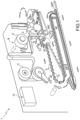
Figure 1 , reference numeral 1 indicates, as a whole, an automatic machine for manufacturingarticles 3 of the tobacco industry, in particular an automatic packaging machine 1 for applying a transparent overwrapping to cigarette packs. The automatic machine 1 comprises different parts, which are in turn provided with one or more work stations WS configured to carry out processing operations on semi-finished articles 3 (for example, the cigarette packs in the embodiment illustrated inFigure 1 ). In particular, the automatic machine 1 comprises a part 2 provided with aconveying system 4, which is configured to convey, singularly or in groups, thesemi-finished articles 3 along a conveying path CP and according to a first periodic motion law. - In the non-limiting embodiment of
Figures 2 and3 , theconveying system 4 comprises abelt 5 configured to receive somesemi-finished articles 3 and transport them towards a processing station WS. In particular, acomponent 6, in this case a wrapping, for example a transparent overwrapping, is applied in the processing station WS. Obviously, thecomponent 6 can be any type of element to be added to thearticle 3 such as, for example, a collar, a glue, a support, a fastening element, a label, a blank, an absorbent sheet, an elastic, a foodstuff, etc. In the following description, in a non-limiting manner,reference numeral 3 will indicate the consumer articles in general and reference numeral 3' will indicate the consumer article being processed. Moreover,reference numeral 6 will indicate the components in general, reference numeral 6' will indicate the defective components andreference numeral 6" will indicate the new components, succeeding the defective components 6'. - Advantageously but not necessarily, the
conveying system 4 also comprises one ormore pushers 7. In some non-limiting cases, thepushers 7 are set in motion byactuators 13 independent of one another and by thebelt 5. In other non-limiting cases, thepushers 7 are set in motion by a single actuating system that is independent of thebelt 5. In further non-limiting cases, thepushers 7 are integral with theconveyor belt 5. - Advantageously, the automatic machine 1 comprises at least one store (8) containing one or
more components 6. - In some non-limiting cases such as the one illustrated in the accompanying figures, the
component 6 is a planar element, in particular a strip, a wrapping or a blank. - In the non-limiting embodiment of
Figures 2 and3 , thecomponent 6 is obtained from a seamless strip, which is fed, cut and possibly rejected along a feeding path FP. In other words, thecomponent 6 is a continuous strip of wrapping material and thestore 8 is thus a reel C. In other non-limiting embodiments not illustrated, thestore 8 comprises a plurality of separate (for example collars or blanks) and stored (for example in piles) components. - The part 2 of the automatic machine 1 further comprises a
feeding system 9 configured to feed at least onecomponent 6 from therespective store 8 towards the conveying path CP and along the feeding path FP and according to a second periodic motion law, in particular different from the first periodic motion law which governs the movement of thearticles 3. - In the non-limiting embodiment of
Figures 2 and3 , the part 2 further comprises awheel 10 mounted rotatable around a central rotation axis A and provided with seats 11 (in particular pockets) adapted to accommodate the semi-finished articles 3 (the cigarette packs) and (at least) onepusher 7 adapted to push thesemi-finished articles 3 into theseats 11 of themovable wheel 10. In particular, during the insertion of thesemi-finished articles 3 into theseats 11, thearticle 3 being processed (i.e. the one inside the work station WS) goes towards thecomponent 6 and pushes it into theseat 11 of themovable wheel 10 so as to remain wrapped up therein. - According to some preferred but non-limiting embodiments, the actuators that set in motion the conveying device 4 (and/or the pushers 7) and/or the
feeding system 9 comprise electric motors (in particular of brushless type) which are independent of one another. According to further embodiments not illustrated, the actuators also comprise types of actuation different from the electric motors (for example pneumatic or hydraulic cylinders, electrically actuated cylinders, etc.). - In the non-limiting embodiment illustrated in
Figures 2 and3 , at least threeactuators first actuator 12 is coupled to thewheel 10 so as to control the rotation of thewheel 10 around the rotation axis A and it is provided with a rotating electric motor (for example of brushless type) which sets thewheel 10 into rotation through the interposition of a reducer (not illustrated); asecond actuator 13 is coupled to thepusher 7 to control the linear movement of thepusher 7 along a direction D and for a predefined stroke and it is provided with a rotating electric motor (for example of brushless type) and with a reducer which transforms the circular movement into a linear movement (both not illustrated); and, in particular, athird actuator 14 connected to thestore 8 and configured to feed thecomponents 6 along the feeding path FP (obviously, theactuator 14 can be any other type of actuator comprising, for example, articulated quadrilaterals, robots, gripping and laying elements, etc.). - Advantageously, the machine 1 further comprises a
control system 15 configured to detect, during the feeding of thecomponents 6, the quality and/or the position and/or the orientation of at least onecomponent 6 so as to establish whether the component is usable or defective. For example, acomponent 6 can be considered defective if it has wrinkles, creases, holes, tears, stains, non-constant thickness, unsuitable dampness, wrong position, incorrect inclination, etc. Conversely, a component is to be considered suitable if it respects all the minimum specifications of quality and/or orientation and/or position. - In the non-limiting embodiment of
Figures 2 and3 , thecontrol system 15 is acamera 16, which, for eachcomponent 6 passing in front of it, performs a scan (i.e. a photo) so as to determine the quality, the orientation and the position thereof and define whether it is defective or suitable. Advantageously but not necessarily, thecamera 16 is comprised in a viewing system (in turn comprised in the control system 15) and in a processing system of the images of a known type and not illustrated to a greater extent. - In other non-limiting embodiments not illustrated, the
control system 15 is any type of sensor capable of establishing the quality and/or the position and/or the orientation of a product (for example, ultrasound sensors, capacitive sensors, microwave sensors, photoelectric cells, etc.). - The automatic machine 1 further comprises a control unit 17 (schematically illustrated in
Figure 1 ) configured to control at least the conveying system 4 (by means of the actuator 13) and feeding system 9 (by means of the actuator 14). Advantageously but not necessarily, thecontrol unit 17 also controls the wheel 10 (by means of the actuator 12) and, in particular, all the actuators of the part 2 of the automatic machine 1. For example, thecontrol unit 17 is the processor of an industrial control unit or an industrial PC. - Advantageously, the
control unit 17 is configured to control, in case the component 6' fed is defective, the conveyingsystem 4 according to a first modified motion law, which is different from the first periodic motion law, so as to convey the article 3' being processed. Alternatively or additionally, thecontrol unit 17 is configured to control thefeeding system 9 according to a second modified motion law, which is different from the second periodic motion law, so as to feed thenew component 6" replacing the defective component 6'. More specifically, in the non-limiting embodiment of the illustrated figures, in case a component 6' is defined defective by thecontrol system 15, the article 3' in the processing step slows down and/or the (usable)component 6" succeeding the defective component 6' accelerates so as to give thefeeding system 9 the time necessary to position the succeedingcomponent 6" in the work station WS before the article 3' goes through the feeding path and pushes it into theseat 11. In particular, the defective component 6' is previously conveyed towards a waste zone WZ (for example a container). - In particular, the
control unit 17 is configured to process, in case a component 6' fed is defective (as illustrated in the non-limiting embodiment ofFigure 3 ), the first and/or the second modified motion law, which comprise respectively (at least) a deceleration (at least) of the article 3' being processed and/or an acceleration of thenew component 6". In such manner, it is possible to compensate the replacement of the defective component 6' with theusable component 6" so as to allow the part 2 of the automatic machine 1 to add to the article 3' being processed at least thenew component 6" replacing the defective component 6'. - In the non-limiting embodiment of
Figures 2 and3 , the part 2 of the automatic machine 1 comprises aseparation device 18 that separates thecomponents device 19 that cuts thecomponents - According to a further aspect of the present invention, a procedure is provided for the selective management of the waste of at least a part of an automatic machine for manufacturing or packing consumer articles.
- The procedure comprises at least a step of conveying, according to the first periodic motion law, the plurality of
semi-finished articles 3 along the conveying path CP through (at least) the work station (WS), where (at least) thecomponent - The procedure comprises the further step, in particular at least partially simultaneous with the conveying step, of feeding each
component Figures 2 and3 , from the reel C) towards the conveying path CP and along the feeding path FP. - Moreover, the procedure comprises a step of checking, in a control area IA and during the step of feeding the
component 6, 6' (i.e. before saidcomponent 6, 6' reaches the conveying path CP and not compulsorily during the movement of thecomponent 6, 6' along the feeding path FP) the quality and/or the position and/or the orientation of the component and establishing whether the component is usable or defective. In particular, during the feeding of eachcomponent component component control unit 17, for the possible variation of the motion laws of the component 3' being processed (i.e. the one which should have received the defective component 6',Figure 3 ) and/or of the succeedingcomponent 6". - Advantageously, in case the
component 6 is a defective component 6', the procedure also comprises a replacement step, during which the defective component 6' is conveyed from the control area IA to a waste zone WZ and replaced, inside the work station WS, by anew component 6", which is fed from therespective store 8 towards the conveying path CP and along the feeding path FP. In this manner, it is possible to carry out a selective rejection of the defective components 6' only. - According to some non-limiting embodiments, in case the
component 6 is a defective component 6', the procedure further comprises a compensation step, during which the article 3' being processed (i.e. the one that should have received the defective component 6') is conveyed according to a first modified motion law (different from the first periodic motion law with which it is normally conveyed) along the conveying path CP, allowing thenew component 6" from therespective store 8 to reach the work station WS. - Alternatively or additionally, during the compensation step, the
new component 6" is fed according to a second modified motion law (different from the second periodic motion law with which it is normally conveyed), allowing thenew component 6" to reach the work station WS in order to be added to the article 3' being processed. - Advantageously but not necessarily, the first modified motion law (i.e. the profiles of position, speed, acceleration, etc., which derive therefrom), compared to the first periodic motion law, comprises a step of decelerating the article 3' being processed. In this case, the term "deceleration" also means the case where, at a certain point of the first modified motion law, there is a lesser acceleration (or a greater deceleration) compared to the same point of the first periodic motion law. In particular, the deceleration step is carried out at the beginning of the compensation step. In such manner, the article 3' being processed "waits" for the
new component 6" to reach the work station. - In some non-limiting cases, as soon as the
component 6" reaches a position owing to which the production can continue normally, the compensation step ends with an acceleration step of the article 3'. In particular, thecontrol unit 17 resumes the conveying of the article 3' according to the first periodic motion law. More precisely, the acceleration step of the article 3' follows a motion profile which joins (interpolates) the first modified motion law (specifically, the position in which the article 3' is now located) to the first periodic motion law (specifically, the position in which the article 3' will have to be located in order to receive thecomponent 6"). - Advantageously but not necessarily, the second modified motion law (i.e. the profiles of position, speed, acceleration, etc., which derive therefrom), compared to the second periodic motion law, comprises a step of accelerating the article 3' being processed. In this case, the term "acceleration" also means the case where, at a certain point of the second modified motion law, there is a greater acceleration (or a lesser deceleration) compared to the same point of the second periodic motion law. In particular, the acceleration step is carried out at the beginning of the compensation step. In such manner, the
new component 6" "chases" the arrival of the article 3' being processed at the work station. - In some non-limiting cases, as soon as the
component 6" reaches a position owing to which the production can continue normally, the compensation step ends with a deceleration step of thecomponent 6". In particular, thecontrol unit 17 resumes the conveying of thecomponent 6" according to the second periodic motion law. More precisely, the deceleration step of thecomponent 6" follows a motion profile which joins (interpolates) the second modified motion law (specifically, the position in which thecomponent 6" is now located) to the second periodic motion law (specifically, the position in which thecomponent 6" will have to be located in order to be received by the article 3' being processed). - Advantageously but not necessarily, the replacement step and the compensation step are at least partially simultaneous. In such manner, it is possible to reduce the deceleration of the article 3' being processed and/or the acceleration of the
new component 6". - Advantageously but not necessarily, the procedure comprises a further step, prior to the compensation step, of processing, by means of the
control unit 17 and in case thecomponent 6 is defective, the first modified motion law and/or the second modified motion law based on the current kinematics and/or on the size of the article 3' being processed. More precisely, in case where the automatic machine 1 produces small formats (or has abundant distances between a work station and the following one) it will be simpler to complete the replacement step and thus the dynamics of the modified motion laws will be "softer" compared to the case where large formats are manufactured (or there are smaller distances between a work station and the following one), in which, in order to dispose of the defective components 6', less "soft" dynamics are necessary. In particular, the modified motion laws are calculated by means of known methods of interpolation of points for an electric actuator such as, for example, splines or polynomials (or by imposing the maximum possible accelerations/decelerations for theactuators - According to some non-limiting embodiments, the
semi-finished articles 3 prior to and/or following the one 3' being processed and subjected to the compensation step (i.e. even only in deceleration) keep being conveyed (normally) along the conveying path CP. In such manner, the general production of the automatic machine 1 is kept on average constant and the compensation step of a single component does not determine any variation in the production of the others. - In some non-limiting cases, the compensation step concerns the single article 3' being processed which should have received the defective component 6'.
- In other non-limiting cases, the compensation step concerns the article 3' being processed which should have received the defective component 6' and a finite number of the
articles 3 which follow it. - Advantageously but not necessarily, the modified motion law comprises at least a first step, during which there is both a deceleration of the article 3', and (or alternatively) an acceleration of the
new component 6". More precisely, the modified motion law also comprises a second step, during which there is both an acceleration of the article 3', and (or alternatively) a deceleration of thenew component 6", in particular so as to re-establish the same speeds provided for by the periodic motion law. In such manner, the disruption of the coupling between thecomponent 6" and the article 3' inside the work station WS is prevented. - Advantageously but not necessarily, the step of checking the quality and/or the position and/or the orientation of the
component new component 6" going along the feeding path (FP). - Advantageously but not necessarily, the
new component 6", preceded by a defective component 6', accelerates its motion towards the work station WS reducing the feeding timing and thus the compensation step of the article 3' being processed. - In particular, especially in case of a succession of several defective components 6', during the compensation step, the article 3' being processed slows down until it temporarily stops (and along the conveying path CP) for a stopping time. The article 3' being processed goes back to moving when the
control system 15 detects a newusable component 6" (the defective components 6' are all conveyed into the waste zone WZ). - In some non-limiting preferred cases, during the compensation step, the
semi-finished articles 3 upstream of the article 3' being processed are conveyed according to a third modified motion law, different from the first modified motion law, the third modified motion law comprises a deceleration step having a peak which is smaller, in module, compared to the first modified motion law. In other words, the third modified motion law allows thesemi-finished articles 3 upstream of the article 3' being processed to slow down in a differentiated manner (more precisely with a less abrupt deceleration) compared to the article 3' in the processing step (which, being the first in the line moving towards the work station WS and thus the one at a smaller distance from the work station WS, has less space to reduce its speed). Specifically, during the normal production thesemi-finished articles 3 upstream of the article 3' being processed are controlled with a third periodic motion law, corresponding to the first periodic motion law. - According to a preferred but non-limiting embodiment, the
actuator 13 which conveys the article 3' being processed is controlled, in particular by thecontrol unit 17, according to the first motion law (alternatively periodic or modified). - Alternatively or additionally, the
actuator 14 which conveys thecomponent 6 towards the work station WS is controlled, in particular by thecontrol unit 17, according to the second motion law (alternatively periodic or modified). - In some further non-limiting cases, the
actuator 13 which conveys the article (or the articles) 3 upstream of the article 3' being processed is controlled, in particular by thecontrol unit 17, according to the third motion law (alternatively periodic or modified). - Advantageously but not necessarily, by exploiting the maximum acceleration (positive and negative) of the
actuator 14 and of theactuator 13 which controls the conveying system 4 (more precisely the pusher 7), the stopping time is maximized and, consequently, also the number of defective components 6' which the described procedure allows compensating without interrupting the production. - In particular, the stopping time has a predetermined upper limit, more precisely below five (preferably two) seconds. In the non-limiting case in which the upper limit of the stopping time is exceeded, the
semi-finished articles 3 downstream of the stationary article 3' continue their possible further processing operations (until exiting the machine 1), in particular until the automatic machine 1 is emptied of all thearticles 3 downstream of the article 3' in compensation step. - Advantageously but not necessarily, upon the succession of a predefined number of defective components 6' (for example five), the
control system 15 signals an error to the control unit and the part 2 of the automatic machine 1 stops in a controlled manner, in particular signalling the error to a machine operator or to a management system. In these cases, the succession of several consecutive defective components 6' means that a part or a station of the machine 1 along the feeding path FP is ruining thecomponents 6 or that the store (or reel) has to be changed because damaged (perhaps during the transport towards the production site). - In the non-limiting embodiment of
Figures 2 and3 , the conveying path CP is divided into a plurality of zones. In particular, the conveying path CP comprises possible compensation zones VS, in which the article 3' being processed can be conveyed according to the first modified motion law. In other words, in the possible compensation zones VS, the speed of the article 3' being processed along the conveying path CP depends on the usability of thecomponents control unit 17 varies the motion laws of thearticles 3, 3' in case of defective (and thus to be rejected) components 6'. - In some non-limiting cases, the conveying path CP also comprises predefined speed zones CS, in which the article 3' being processed is exclusively conveyed according to the first periodic motion law. In other words, in these zones CS, the speed of the
article 3 does not depend on the usability of thecomponents 6 to be added to saidarticle 3. For example, the zones CS are the transport zones far from the work stations WS or correspond to the areas in which the variability of the speed of the articles would compromise the quality of the manufacturing process. - In some non-limiting embodiments, such as the one illustrated in
Figures 2 and3 , the defective component 6' is rejected moving on along the feeding path FP and going through the conveying path CP. In such manner, the defective component 6' is dropped into the waste zone WZ and the followingnew component 6" continues its motion towards the conveying path CP. - In other non-limiting embodiments not illustrated, the defective component 6' is rejected inside the zone WZ without going through the conveying path CP (for example by means of a suitable discharge, suction, exchange, etc. apparatus).
-
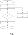
Figure 4 illustrates a possible and non-limiting flowchart of the procedure for the selective management of the waste of at least a part of an automatic machine for manufacturing or packing consumer articles. - In such flowchart, the rectangular blocks are processing blocks in which operations are carried out by the
control unit 15, while the rhomboidal blocks are six control or checking blocks in which certain conditions are checked; at the outlet of such blocks, the continuous arrows indicate that such conditions have been checked, while the broken arrows indicate that such conditions have not been checked. -
Reference numeral 20 indicates the beginning block of the procedure, indicating the starting step of the part 2 of the automatic machine 1 and thus of theactuators semi-finished articles 3 andcomponents 6. Inside theblock 21, acomponent 6 is collected from thestore 8 and set in motion (in particular by means of the actuator 14) along the feeding path FP towards the conveying path CP (where the work station WS is located). At the same time, anarticle 3 is conveyed (in particular by means of the actuator 13) towards the work station WS so as to receive the respective component 6 (in the case of the embodiment ofFigures 2 and3 , in wrapping strip). Thecomponent 6 is subsequently controlled (scanned, photographed) by the control system 15 (in particular by the camera 16) in theblock 22. Following such control, (block 23) the control system (or the control unit in connection thereto) determines whether the quality, the position and the orientation of thecomponent 6 respect the required manufacturing specifications and therefore whether thecomponent 6 is usable or defective. If it is usable, the flow carries on towards theblock 24, inside which the article 3' being processed receives theusable component 6. In the case of the embodiments ofFigures 2 and3 , the article 3' pushes theusable component 6 into thepocket 11 of thewheel 10 and the production carries on (block 27) with the subsequent folding of the flaps of thecomponent 6 so as to close the wrapping. If, instead, following the control, it is established in theblock 23 that thecomponent 6 is a defective component 6', the flow diverts towards theblock 25, in which thecontrol unit 17 processes a modified motion law for thefollowing component 6" (which accelerates) and/or for the article 3' being processed (which decelerates, giving thecomponent 6" time to reach the work station WS). Once the modified motion law has been processed, it is imposed on theactuators block 26, after which thenew component 6" is controlled. Such procedure continues in a recursive manner. - In some advantageous but non-limiting, embodiments, the control of the
component control unit 17 knows the number of consecutive defective components 6' (up to a finite maximum, as described above) and thus of the following newusable component 6". In this case, in processing the modified motion law, thecontrol unit 17 also considers the rejection of possible consecutive defective components, varying the deceleration of the article 3' being processed (and possibly the acceleration of thenew component 6" to be fed) so as to compensate also the plurality of consecutive rejections. - Advantageously but not necessarily, the automatic machine 1 is configured to carry out the procedure described in the foregoing.
- Although the above-described invention refers in particular to a very precise embodiment example, it is not to be understood as limited to such embodiment example, falling within the scope of the appended claims.
- The present invention has multiple advantages. First of all, it allows rejecting only the defective components and not an entire article in which a plurality of usable components are also present. In such manner, it improves the efficiency of the manufacturer in terms of wastage of usable material, the waste is generally reduced and therefore there is a greater sustainability of the process and lower disposal and raw material costs.
- Moreover, the possibility of independently controlling the various actuators and checking the number of consecutive rejections allows preventing that the machine jams out of control, enabling, simultaneously, the completion of the production of the articles downstream of the part of the machine that stops during a step.
- Additionally, the possibility of controlling in a diversified manner the conveying of the articles and the feeding of the components, allows maximizing the compensation step and continuing the production despite several consecutive defective components have been fed.
- Finally, joining the modified motion laws to the respective periodic motion laws allows the articles being processed to recover the position lost during the compensation step and carry on the production of the consumer articles without interruptions.
Claims (14)
- A procedure for the selective management of the waste of at least part (2) of an automatic machine (1) for manufacturing or packing consumer articles; the procedure comprises the steps of:conveying, according to a first periodic motion law, a plurality of semi-finished articles (3) along a conveying path (CP) through at least one work station (WS), where at least one component (6, 6") is added to an article (3') being processed;feeding, according to a second periodic motion law, each component (6, 6', 6") from a respective store (8) towards the conveying path (CP) and along a feeding path (FP);checking, in a control area (IA) and during the step of feeding the component (6, 6', 6"), the quality and/or the position and/or the orientation of the component (6, 6', 6'') itself and establishing whether the component (6, 6', 6") is usable or defective;the method being characterized in that it comprises, in case the component (6, 6', 6") is faulty, a replacement step, during which the defective component (6') is conveyed from the control area (IA) to a waste zone (WZ) and is replaced, inside the work station (WS), by a new component (6"), which is fed from the store (8) towards the conveying path (CP) and along the feeding path (FP); and a compensation step, during which the article (3') being processed is conveyed according to a first modified motion law and the new component (6") is conveyed according to a second modified motion law, thus allowing the new component (6") to reach the work station (WS) so that it can be added to the article (3') being processed;the method comprising a further step, prior to the compensation step, of processing, by means of a control unit and in case the component (6, 6', 6") fed is defective, at least the first modified motion law and/or the second modified motion law based on the current kinematics and/or on the size of the article (3') being processed.
- A procedure according to claim 1, wherein the first modified motion law, compared to the first periodic motion law, comprises a step of decelerating the article (3') being processed, in particular the deceleration step is carried out at the beginning of the compensation step.
- A procedure according to claim 1 or 2, wherein the second modified motion law, compared to the second periodic motion law, comprises a step of accelerating the new component (6"), in particular the acceleration step is carried out at the beginning of the compensation step.
- A procedure according to any one of the preceding claims, wherein the semi-finished articles (3) prior to and/or following the one (3') being processed and subjected to the compensation step keep being conveyed along the conveying path (CP), in particular according to the first periodic motion law.
- A procedure according to any one of the preceding claims, wherein the replacement step and the compensation step are at least partially simultaneous.
- A procedure according to any one of the preceding claims, wherein the step of checking the quality and/or the position and/or the orientation of the component (6, 6', 6") is cyclically repeated for each new component (6") going through the control area (IA) and along the feeding path (FP).
- A procedure according to any one of the preceding claims, wherein, during the compensation step, the article (3') being processed slows down until it temporarily stops for a stopping time.
- A procedure according to claim 7, wherein the stopping time has a predetermined upper limit, in particular below five seconds.
- A procedure according to claim 8, wherein, if the upper limit of the stopping time is exceeded, the part (2) of the automatic machine (1) stops in a controlled manner, in particular signalling an error to an operator or to a management system.
- A procedure according to any one of the claims from 7 to 9, wherein, if the upper limit of the stopping time is exceeded, the semi-finished articles (3) downstream of the article (3') being stopped carry on with possible further processing operations, in particular until the automatic machine (1) is empty.
- A procedure according to any one of the preceding claims, wherein, during the compensation step, the semi-finished articles (3) upstream of the article (3') being processed are conveyed according to a third modified motion law, which is different from the first modified motion law; in particular, the third modified motion law comprises a deceleration step having a peak which is smaller, in module, compared to the first modified motion law.
- A procedure according to any one of the preceding claims, wherein, for each article, the conveying path (CP) is divided into possible compensation zones (VS), in which the article (3') being processed can be conveyed according to the first modified motion law; and predefined speed zones (CS), in which the article (3') being processed is exclusively conveyed according to the first periodic motion law.
- A procedure according to any one of the preceding claims, wherein a defective component (6) is rejected moving on along the feeding path (FP) and going through the conveying path (CP).
- An automatic machine (1) for manufacturing or packing consumer articles (3); the automatic machine (1) comprises:a conveying system (4), which is configured to convey, singularly or in groups, a plurality of semi-finished articles (3) along a conveying path (CP) and according to a first periodic motion law;at least one store (8) containing one or more components;a feeding system (9), which is configured to feed at least one component (6) from the respective store (8) towards the conveying path (CP) and along a feeding path (FP) as well as according to a second periodic motion law;a control system (15) configured to detect, during the feeding of the components, the quality and/or the position and/or the orientation of at least one component (6) so as to establish whether the component (6) is usable or defective; anda control unit (17), which is configured to control at least the conveying system (4) and the feeding system (9);a waste zone (WZ) configured to receive possible defective components;the automatic machine (1) is characterized in that:the control unit (17) is configured to control, in case the component (6') fed is defective, the conveying system (4) according to a first modified motion law, which is different from the first periodic motion law, so as to convey the article (3') being processed and to control the feeding system (9) according to a second modified motion law, which is different from the second periodic motion law, so as to feed the new component (6") replacing the defective component (6');the control unit (17) is configure to process, in case the component (6, 6', 6") fed is defective, at least the first modified motion law and/or the second modified motion law based on the current kinematics and/or on the size of the article (3') being processed.
Applications Claiming Priority (2)
| Application Number | Priority Date | Filing Date | Title |
|---|---|---|---|
| IT202000001993 | 2020-02-03 | ||
| PCT/IB2021/050865 WO2021156759A1 (en) | 2020-02-03 | 2021-02-03 | Procedure for the selective management of the waste of an automatic machine for manufacturing or packing consumer articles |
Publications (2)
| Publication Number | Publication Date |
|---|---|
| EP4100328A1 EP4100328A1 (en) | 2022-12-14 |
| EP4100328B1 true EP4100328B1 (en) | 2025-04-09 |
Family
ID=70480486
Family Applications (1)
| Application Number | Title | Priority Date | Filing Date |
|---|---|---|---|
| EP21709093.5A Active EP4100328B1 (en) | 2020-02-03 | 2021-02-03 | Procedure for the selective management of the waste of an automatic machine for manufacturing or packing consumer articles |
Country Status (3)
| Country | Link |
|---|---|
| EP (1) | EP4100328B1 (en) |
| PL (1) | PL4100328T3 (en) |
| WO (1) | WO2021156759A1 (en) |
Citations (3)
| Publication number | Priority date | Publication date | Assignee | Title |
|---|---|---|---|---|
| DE3639972A1 (en) * | 1986-11-22 | 1988-05-26 | Hauni Werke Koerber & Co Kg | Process and device for separating out from a material web material web sections which are unusable as a result of defects |
| EP0957028A1 (en) * | 1998-05-14 | 1999-11-17 | MARCHESINI GROUP S.p.A. | Method for packaging articles into containers |
| DE102018105269A1 (en) * | 2018-03-07 | 2019-09-12 | Krones Aktiengesellschaft | Packaging device for articles and methods for providing sheet-like packaging blanks for articles |
Family Cites Families (5)
| Publication number | Priority date | Publication date | Assignee | Title |
|---|---|---|---|---|
| DE3876206D1 (en) * | 1987-10-16 | 1993-01-07 | Hauni Werke Koerber & Co Kg | METHOD AND DEVICE FOR PACKING SINGLE PACKS IN GROUPS. |
| IT1238549B (en) * | 1990-04-11 | 1993-08-18 | Gd Spa | EQUIPMENT FOR FEEDING PRODUCTS. |
| ITBO20060019A1 (en) * | 2006-01-16 | 2007-07-17 | Gd Spa | METHOD AND MACHINE FOR PACKAGING / WRAPPING A PRODUCT USING AT LEAST A PRINTED SHEET |
| DE102012025158A1 (en) * | 2012-12-21 | 2014-06-26 | Focke & Co. (Gmbh & Co. Kg) | Method and device for the automatic testing of flat sheet material |
| IT201800004698A1 (en) * | 2018-04-19 | 2019-10-19 | Procedure for restoring the functional state of an automatic machine for the production of items for the tobacco industry |
-
2021
- 2021-02-03 PL PL21709093.5T patent/PL4100328T3/en unknown
- 2021-02-03 WO PCT/IB2021/050865 patent/WO2021156759A1/en not_active Ceased
- 2021-02-03 EP EP21709093.5A patent/EP4100328B1/en active Active
Patent Citations (3)
| Publication number | Priority date | Publication date | Assignee | Title |
|---|---|---|---|---|
| DE3639972A1 (en) * | 1986-11-22 | 1988-05-26 | Hauni Werke Koerber & Co Kg | Process and device for separating out from a material web material web sections which are unusable as a result of defects |
| EP0957028A1 (en) * | 1998-05-14 | 1999-11-17 | MARCHESINI GROUP S.p.A. | Method for packaging articles into containers |
| DE102018105269A1 (en) * | 2018-03-07 | 2019-09-12 | Krones Aktiengesellschaft | Packaging device for articles and methods for providing sheet-like packaging blanks for articles |
Also Published As
| Publication number | Publication date |
|---|---|
| PL4100328T3 (en) | 2025-06-23 |
| EP4100328A1 (en) | 2022-12-14 |
| WO2021156759A1 (en) | 2021-08-12 |
Similar Documents
| Publication | Publication Date | Title |
|---|---|---|
| US11834211B2 (en) | Packing machine for paper product converting line and method for packing of paper products | |
| EP1740460B1 (en) | A method and a unit for producing blister packs by cutting a blister band | |
| EP3716792B1 (en) | A replenishing device, an apparatus for manufacturing multisegment rods and a method for manufacturing multi-segment rods | |
| US20120108408A1 (en) | Thermoform packaging machine and method of operating the same | |
| US7448187B2 (en) | Installation for producing and packing tubes | |
| US7690498B2 (en) | Method for transferring a product in a packaging machine and transfer device for carrying out said method | |
| EP0957028B1 (en) | Method for packaging articles into containers | |
| JPS5926532B2 (en) | Packaging material detection and disposal device for cigarette packaging machines | |
| US20080138187A1 (en) | Method For Handling a Blister in a Blister Packaging Machine and Device For Carrying Out Said Method | |
| EP4100328B1 (en) | Procedure for the selective management of the waste of an automatic machine for manufacturing or packing consumer articles | |
| US6122898A (en) | Packaging machine | |
| CN102015462A (en) | Packaging machine for a collection of articles, method for producing a collection of articles and collection of articles | |
| JP3983756B2 (en) | Punching stage | |
| US8925713B2 (en) | Method for operating a processing system, in which product units having different product characteristics are processed | |
| EP4371894A1 (en) | Process for the management of waste with semifinished product recirculation for an automatic machine for manufacturing or packing consumer articles | |
| US6971213B2 (en) | Method for the separate rejection of defective items, in particular strip packages, during transferring from a packaging line to a conveying line | |
| EP1848637B1 (en) | A machine for filling box-like containers with articles arranged side by side and vertically | |
| JP6117739B2 (en) | Horizontal bag making and filling machine and control method thereof | |
| JP2841204B2 (en) | Packaging method and equipment | |
| EP3713863B1 (en) | Triple drive system integrated to the cutting machines | |
| US20260077896A1 (en) | Machine for forming filter bags for infusion products | |
| ITSV980036A1 (en) | OPERATING METHOD AND OPERATING MACHINE, IN PARTICULAR IN CIGARETTE PACKING MACHINES, OR SIMILAR. | |
| JP2860344B2 (en) | Packaging method and equipment | |
| JPH03292135A (en) | Bag making machine capable of detecting bend of bag body | |
| JP5962324B2 (en) | Sheet blank detection system |
Legal Events
| Date | Code | Title | Description |
|---|---|---|---|
| STAA | Information on the status of an ep patent application or granted ep patent |
Free format text: STATUS: UNKNOWN |
|
| STAA | Information on the status of an ep patent application or granted ep patent |
Free format text: STATUS: THE INTERNATIONAL PUBLICATION HAS BEEN MADE |
|
| TPAC | Observations filed by third parties |
Free format text: ORIGINAL CODE: EPIDOSNTIPA |
|
| PUAI | Public reference made under article 153(3) epc to a published international application that has entered the european phase |
Free format text: ORIGINAL CODE: 0009012 |
|
| STAA | Information on the status of an ep patent application or granted ep patent |
Free format text: STATUS: REQUEST FOR EXAMINATION WAS MADE |
|
| 17P | Request for examination filed |
Effective date: 20220808 |
|
| AK | Designated contracting states |
Kind code of ref document: A1 Designated state(s): AL AT BE BG CH CY CZ DE DK EE ES FI FR GB GR HR HU IE IS IT LI LT LU LV MC MK MT NL NO PL PT RO RS SE SI SK SM TR |
|
| STAA | Information on the status of an ep patent application or granted ep patent |
Free format text: STATUS: EXAMINATION IS IN PROGRESS |
|
| 17Q | First examination report despatched |
Effective date: 20230130 |
|
| DAV | Request for validation of the european patent (deleted) | ||
| DAX | Request for extension of the european patent (deleted) | ||
| P01 | Opt-out of the competence of the unified patent court (upc) registered |
Effective date: 20230529 |
|
| TPAC | Observations filed by third parties |
Free format text: ORIGINAL CODE: EPIDOSNTIPA |
|
| GRAP | Despatch of communication of intention to grant a patent |
Free format text: ORIGINAL CODE: EPIDOSNIGR1 |
|
| STAA | Information on the status of an ep patent application or granted ep patent |
Free format text: STATUS: GRANT OF PATENT IS INTENDED |
|
| INTG | Intention to grant announced |
Effective date: 20240913 |
|
| GRAS | Grant fee paid |
Free format text: ORIGINAL CODE: EPIDOSNIGR3 |
|
| GRAA | (expected) grant |
Free format text: ORIGINAL CODE: 0009210 |
|
| STAA | Information on the status of an ep patent application or granted ep patent |
Free format text: STATUS: THE PATENT HAS BEEN GRANTED |
|
| AK | Designated contracting states |
Kind code of ref document: B1 Designated state(s): AL AT BE BG CH CY CZ DE DK EE ES FI FR GB GR HR HU IE IS IT LI LT LU LV MC MK MT NL NO PL PT RO RS SE SI SK SM TR |
|
| REG | Reference to a national code |
Ref country code: GB Ref legal event code: FG4D |
|
| REG | Reference to a national code |
Ref country code: CH Ref legal event code: EP |
|
| REG | Reference to a national code |
Ref country code: DE Ref legal event code: R096 Ref document number: 602021028874 Country of ref document: DE |
|
| REG | Reference to a national code |
Ref country code: IE Ref legal event code: FG4D |
|
| REG | Reference to a national code |
Ref country code: NL Ref legal event code: FP |
|
| REG | Reference to a national code |
Ref country code: AT Ref legal event code: MK05 Ref document number: 1783365 Country of ref document: AT Kind code of ref document: T Effective date: 20250409 |
|
| PG25 | Lapsed in a contracting state [announced via postgrant information from national office to epo] |
Ref country code: FI Free format text: LAPSE BECAUSE OF FAILURE TO SUBMIT A TRANSLATION OF THE DESCRIPTION OR TO PAY THE FEE WITHIN THE PRESCRIBED TIME-LIMIT Effective date: 20250409 Ref country code: PT Free format text: LAPSE BECAUSE OF FAILURE TO SUBMIT A TRANSLATION OF THE DESCRIPTION OR TO PAY THE FEE WITHIN THE PRESCRIBED TIME-LIMIT Effective date: 20250811 Ref country code: ES Free format text: LAPSE BECAUSE OF FAILURE TO SUBMIT A TRANSLATION OF THE DESCRIPTION OR TO PAY THE FEE WITHIN THE PRESCRIBED TIME-LIMIT Effective date: 20250409 |
|
| REG | Reference to a national code |
Ref country code: LT Ref legal event code: MG9D |
|
| PG25 | Lapsed in a contracting state [announced via postgrant information from national office to epo] |
Ref country code: NO Free format text: LAPSE BECAUSE OF FAILURE TO SUBMIT A TRANSLATION OF THE DESCRIPTION OR TO PAY THE FEE WITHIN THE PRESCRIBED TIME-LIMIT Effective date: 20250709 Ref country code: GR Free format text: LAPSE BECAUSE OF FAILURE TO SUBMIT A TRANSLATION OF THE DESCRIPTION OR TO PAY THE FEE WITHIN THE PRESCRIBED TIME-LIMIT Effective date: 20250710 |
|
| PG25 | Lapsed in a contracting state [announced via postgrant information from national office to epo] |
Ref country code: BG Free format text: LAPSE BECAUSE OF FAILURE TO SUBMIT A TRANSLATION OF THE DESCRIPTION OR TO PAY THE FEE WITHIN THE PRESCRIBED TIME-LIMIT Effective date: 20250409 |
|
| PG25 | Lapsed in a contracting state [announced via postgrant information from national office to epo] |
Ref country code: HR Free format text: LAPSE BECAUSE OF FAILURE TO SUBMIT A TRANSLATION OF THE DESCRIPTION OR TO PAY THE FEE WITHIN THE PRESCRIBED TIME-LIMIT Effective date: 20250409 |
|
| PG25 | Lapsed in a contracting state [announced via postgrant information from national office to epo] |
Ref country code: AT Free format text: LAPSE BECAUSE OF FAILURE TO SUBMIT A TRANSLATION OF THE DESCRIPTION OR TO PAY THE FEE WITHIN THE PRESCRIBED TIME-LIMIT Effective date: 20250409 |
|
| PG25 | Lapsed in a contracting state [announced via postgrant information from national office to epo] |
Ref country code: RS Free format text: LAPSE BECAUSE OF FAILURE TO SUBMIT A TRANSLATION OF THE DESCRIPTION OR TO PAY THE FEE WITHIN THE PRESCRIBED TIME-LIMIT Effective date: 20250709 |
|
| PG25 | Lapsed in a contracting state [announced via postgrant information from national office to epo] |
Ref country code: IS Free format text: LAPSE BECAUSE OF FAILURE TO SUBMIT A TRANSLATION OF THE DESCRIPTION OR TO PAY THE FEE WITHIN THE PRESCRIBED TIME-LIMIT Effective date: 20250809 |
|
| PG25 | Lapsed in a contracting state [announced via postgrant information from national office to epo] |
Ref country code: LV Free format text: LAPSE BECAUSE OF FAILURE TO SUBMIT A TRANSLATION OF THE DESCRIPTION OR TO PAY THE FEE WITHIN THE PRESCRIBED TIME-LIMIT Effective date: 20250409 |
|
| REG | Reference to a national code |
Ref country code: DE Ref legal event code: R026 Ref document number: 602021028874 Country of ref document: DE |
|
| PLBI | Opposition filed |
Free format text: ORIGINAL CODE: 0009260 |
|
| PG25 | Lapsed in a contracting state [announced via postgrant information from national office to epo] |
Ref country code: DK Free format text: LAPSE BECAUSE OF FAILURE TO SUBMIT A TRANSLATION OF THE DESCRIPTION OR TO PAY THE FEE WITHIN THE PRESCRIBED TIME-LIMIT Effective date: 20250409 Ref country code: SM Free format text: LAPSE BECAUSE OF FAILURE TO SUBMIT A TRANSLATION OF THE DESCRIPTION OR TO PAY THE FEE WITHIN THE PRESCRIBED TIME-LIMIT Effective date: 20250409 |
|
| PG25 | Lapsed in a contracting state [announced via postgrant information from national office to epo] |
Ref country code: CZ Free format text: LAPSE BECAUSE OF FAILURE TO SUBMIT A TRANSLATION OF THE DESCRIPTION OR TO PAY THE FEE WITHIN THE PRESCRIBED TIME-LIMIT Effective date: 20250409 |
|
| PLAX | Notice of opposition and request to file observation + time limit sent |
Free format text: ORIGINAL CODE: EPIDOSNOBS2 |
|
| 26 | Opposition filed |
Opponent name: FOCKE & CO. (GMBH & CO. KG) Effective date: 20251212 |
|
| PG25 | Lapsed in a contracting state [announced via postgrant information from national office to epo] |
Ref country code: EE Free format text: LAPSE BECAUSE OF FAILURE TO SUBMIT A TRANSLATION OF THE DESCRIPTION OR TO PAY THE FEE WITHIN THE PRESCRIBED TIME-LIMIT Effective date: 20250409 |
|
| PG25 | Lapsed in a contracting state [announced via postgrant information from national office to epo] |
Ref country code: SK Free format text: LAPSE BECAUSE OF FAILURE TO SUBMIT A TRANSLATION OF THE DESCRIPTION OR TO PAY THE FEE WITHIN THE PRESCRIBED TIME-LIMIT Effective date: 20250409 |
|
| PG25 | Lapsed in a contracting state [announced via postgrant information from national office to epo] |
Ref country code: IT Free format text: LAPSE BECAUSE OF FAILURE TO SUBMIT A TRANSLATION OF THE DESCRIPTION OR TO PAY THE FEE WITHIN THE PRESCRIBED TIME-LIMIT Effective date: 20250409 |
|
| PGFP | Annual fee paid to national office [announced via postgrant information from national office to epo] |
Ref country code: DE Payment date: 20260227 Year of fee payment: 6 |