EP4100298B1 - Système de direction électromécanique double pour un véhicule utilitaire - Google Patents
Système de direction électromécanique double pour un véhicule utilitaire Download PDFInfo
- Publication number
- EP4100298B1 EP4100298B1 EP21702916.4A EP21702916A EP4100298B1 EP 4100298 B1 EP4100298 B1 EP 4100298B1 EP 21702916 A EP21702916 A EP 21702916A EP 4100298 B1 EP4100298 B1 EP 4100298B1
- Authority
- EP
- European Patent Office
- Prior art keywords
- steering system
- dual
- steering
- circuit
- power supply
- Prior art date
- Legal status (The legal status is an assumption and is not a legal conclusion. Google has not performed a legal analysis and makes no representation as to the accuracy of the status listed.)
- Active
Links
Images
Classifications
-
- B—PERFORMING OPERATIONS; TRANSPORTING
- B62—LAND VEHICLES FOR TRAVELLING OTHERWISE THAN ON RAILS
- B62D—MOTOR VEHICLES; TRAILERS
- B62D5/00—Power-assisted or power-driven steering
- B62D5/04—Power-assisted or power-driven steering electrical, e.g. using an electric servo-motor connected to, or forming part of, the steering gear
- B62D5/0457—Power-assisted or power-driven steering electrical, e.g. using an electric servo-motor connected to, or forming part of, the steering gear characterised by control features of the drive means as such
- B62D5/0481—Power-assisted or power-driven steering electrical, e.g. using an electric servo-motor connected to, or forming part of, the steering gear characterised by control features of the drive means as such monitoring the steering system, e.g. failures
-
- B—PERFORMING OPERATIONS; TRANSPORTING
- B62—LAND VEHICLES FOR TRAVELLING OTHERWISE THAN ON RAILS
- B62D—MOTOR VEHICLES; TRAILERS
- B62D7/00—Steering linkage; Stub axles or their mountings
- B62D7/06—Steering linkage; Stub axles or their mountings for individually-pivoted wheels, e.g. on king-pins
- B62D7/14—Steering linkage; Stub axles or their mountings for individually-pivoted wheels, e.g. on king-pins the pivotal axes being situated in more than one plane transverse to the longitudinal centre line of the vehicle, e.g. all-wheel steering
- B62D7/148—Steering linkage; Stub axles or their mountings for individually-pivoted wheels, e.g. on king-pins the pivotal axes being situated in more than one plane transverse to the longitudinal centre line of the vehicle, e.g. all-wheel steering provided with safety devices
-
- B—PERFORMING OPERATIONS; TRANSPORTING
- B62—LAND VEHICLES FOR TRAVELLING OTHERWISE THAN ON RAILS
- B62D—MOTOR VEHICLES; TRAILERS
- B62D5/00—Power-assisted or power-driven steering
- B62D5/04—Power-assisted or power-driven steering electrical, e.g. using an electric servo-motor connected to, or forming part of, the steering gear
- B62D5/0421—Electric motor acting on or near steering gear
-
- B—PERFORMING OPERATIONS; TRANSPORTING
- B62—LAND VEHICLES FOR TRAVELLING OTHERWISE THAN ON RAILS
- B62D—MOTOR VEHICLES; TRAILERS
- B62D5/00—Power-assisted or power-driven steering
- B62D5/04—Power-assisted or power-driven steering electrical, e.g. using an electric servo-motor connected to, or forming part of, the steering gear
- B62D5/0442—Conversion of rotational into longitudinal movement
- B62D5/0445—Screw drives
-
- B—PERFORMING OPERATIONS; TRANSPORTING
- B62—LAND VEHICLES FOR TRAVELLING OTHERWISE THAN ON RAILS
- B62D—MOTOR VEHICLES; TRAILERS
- B62D5/00—Power-assisted or power-driven steering
- B62D5/04—Power-assisted or power-driven steering electrical, e.g. using an electric servo-motor connected to, or forming part of, the steering gear
- B62D5/0457—Power-assisted or power-driven steering electrical, e.g. using an electric servo-motor connected to, or forming part of, the steering gear characterised by control features of the drive means as such
- B62D5/0481—Power-assisted or power-driven steering electrical, e.g. using an electric servo-motor connected to, or forming part of, the steering gear characterised by control features of the drive means as such monitoring the steering system, e.g. failures
- B62D5/0484—Power-assisted or power-driven steering electrical, e.g. using an electric servo-motor connected to, or forming part of, the steering gear characterised by control features of the drive means as such monitoring the steering system, e.g. failures for reaction to failures, e.g. limp home
-
- B—PERFORMING OPERATIONS; TRANSPORTING
- B62—LAND VEHICLES FOR TRAVELLING OTHERWISE THAN ON RAILS
- B62D—MOTOR VEHICLES; TRAILERS
- B62D7/00—Steering linkage; Stub axles or their mountings
- B62D7/06—Steering linkage; Stub axles or their mountings for individually-pivoted wheels, e.g. on king-pins
- B62D7/14—Steering linkage; Stub axles or their mountings for individually-pivoted wheels, e.g. on king-pins the pivotal axes being situated in more than one plane transverse to the longitudinal centre line of the vehicle, e.g. all-wheel steering
- B62D7/142—Steering linkage; Stub axles or their mountings for individually-pivoted wheels, e.g. on king-pins the pivotal axes being situated in more than one plane transverse to the longitudinal centre line of the vehicle, e.g. all-wheel steering specially adapted for particular vehicles, e.g. tractors, carts, earth-moving vehicles, trucks
-
- B—PERFORMING OPERATIONS; TRANSPORTING
- B62—LAND VEHICLES FOR TRAVELLING OTHERWISE THAN ON RAILS
- B62D—MOTOR VEHICLES; TRAILERS
- B62D5/00—Power-assisted or power-driven steering
- B62D5/04—Power-assisted or power-driven steering electrical, e.g. using an electric servo-motor connected to, or forming part of, the steering gear
- B62D5/0457—Power-assisted or power-driven steering electrical, e.g. using an electric servo-motor connected to, or forming part of, the steering gear characterised by control features of the drive means as such
- B62D5/046—Controlling the motor
-
- B—PERFORMING OPERATIONS; TRANSPORTING
- B62—LAND VEHICLES FOR TRAVELLING OTHERWISE THAN ON RAILS
- B62D—MOTOR VEHICLES; TRAILERS
- B62D7/00—Steering linkage; Stub axles or their mountings
- B62D7/06—Steering linkage; Stub axles or their mountings for individually-pivoted wheels, e.g. on king-pins
- B62D7/14—Steering linkage; Stub axles or their mountings for individually-pivoted wheels, e.g. on king-pins the pivotal axes being situated in more than one plane transverse to the longitudinal centre line of the vehicle, e.g. all-wheel steering
- B62D7/142—Steering linkage; Stub axles or their mountings for individually-pivoted wheels, e.g. on king-pins the pivotal axes being situated in more than one plane transverse to the longitudinal centre line of the vehicle, e.g. all-wheel steering specially adapted for particular vehicles, e.g. tractors, carts, earth-moving vehicles, trucks
- B62D7/144—Steering linkage; Stub axles or their mountings for individually-pivoted wheels, e.g. on king-pins the pivotal axes being situated in more than one plane transverse to the longitudinal centre line of the vehicle, e.g. all-wheel steering specially adapted for particular vehicles, e.g. tractors, carts, earth-moving vehicles, trucks for vehicles with more than two axles
Definitions
- the invention relates to an electromechanical dual-circuit steering system for a commercial vehicle according to the preamble of claim 1 and to a commercial vehicle.
- Hydraulic dual-circuit steering systems are typically used to steer commercial vehicles. These consist of two steering systems, each for a separate steering axle, with the driver's steering effort being hydraulically assisted. During normal operation, both steering systems receive hydraulic assistance from a hydraulic pump driven by the vehicle's main engine. A redundant design requires a vehicle-dependent emergency steering pump, which is switched over in the event of a main engine failure. At the same time, one of the two steering axles is disconnected from the hydraulic assistance to prevent overloading the emergency steering pump. This ensures that the commercial vehicle remains steerable even if the main engine fails.
- the hydraulic system is more complicated than an electric power steering system, so that electrically assisted steering systems are increasingly being used.
- the driver's steering effort is supported by an electric motor, which, as in the US20120241244A1 by means of a transmission on the actual steering axle.
- Combinations of a hydraulically assisted first steering axle and an electrically operated second steering axle are also known.
- Such a dual-circuit steering system is used, for example, in the DE19910001A1 This eliminates the need for hydraulic lines to the second, often rear, axle of a commercial vehicle. Instead, only one cable to the second axle is required.
- the object of the invention is to more effectively protect the operation of an electromechanical dual-circuit steering system for commercial vehicles against failure.
- this object is achieved by the features of the characterising part of claim 1
- this object is achieved by a commercial vehicle having the features of claim 14.
- a key feature of the invention is that in the event of a main power failure, an emergency power supply is activated, supplying at least one of the steering systems with electrical energy, thus ensuring safe steering of the commercial vehicle.
- the electromechanical dual-circuit steering system is for a commercial vehicle and comprises two steering assemblies, each having a drive unit for actuating a respective steering linkage for wheels of the commercial vehicle.
- the two steering assemblies are preferably attached to two different axles of the commercial vehicle. This improves the handling of the commercial vehicle and reduces the turning circle.
- the steering linkage of the wheels can, for example, engage the wheel hub of the respective wheel and thus rotate the wheels about a rotational axis, enabling the vehicle to be steered.
- the wheels of the first axle can be rotated in the same direction as the wheels of the second axle, thus achieving improved handling at higher speeds.
- the wheels of the two axles can, however, also be rotated in opposite directions, thus achieving a smaller turning circle at low speeds.
- each drive unit of the steering systems comprises a respective electric motor.
- the dual-circuit steering system according to the invention comprises a main power supply for supplying the electric motors with electrical energy.
- the electric motors can actuate a steering shaft of the steering system.
- the electric motors can engage directly with a steering shaft or be connected to it via a gear. Other couplings are also conceivable.
- the electric motor can pivot the steering shaft, with the pivoting movement then being converted by a steering gear of the steering system into a translational movement of a steering rod of the steering linkage. In this way, the steering linkage of the wheels is actuated.
- the electromechanical dual-circuit steering system is characterized by the fact that the dual-circuit steering system has at least one emergency power supply to supply an electric motor with energy in the event of a main power failure. Should the main power supply of the commercial vehicle fail, the emergency power supply is able to maintain the steerability of the commercial vehicle by supplying electrical energy to the electric motor of one steering system and setting the other steering system rigidly. This allows the vehicle to be brought to a standstill safely, for example, or, depending on the design of the emergency power supply, to continue operating without interruption.
- the emergency power supply is designed to supply exactly one electric motor with energy.
- a further preferred embodiment of the dual-circuit steering system provides that the dual-circuit steering system has an emergency power supply to supply all electric motors with power in the event of a main power supply failure.
- the emergency power supply system it can be advantageous to set up an emergency power supply that supplies all electric motors of the steering systems with electrical power. This only requires cable connections from the emergency power supply to the respective electric motor. Individual peripherals for each individual steering system can be omitted.
- the dual-circuit steering system comprises a substantially independent emergency power supply for each electric motor.
- a separate emergency power supply is provided for each steering system.
- a further preferred embodiment of the dual-circuit steering system according to the invention is characterized in that the emergency power supply comprises a generator which is configured to be driven by the rolling motion of the commercial vehicle and to supply energy to at least one of the electric motors.
- the emergency power supply comprises a generator which is configured to be driven by the rolling motion of the commercial vehicle and to supply energy to at least one of the electric motors.
- This variant provides an additional generator, which is coupled, for example, to a drive shaft of the commercial vehicle, so that this generator rotates as soon as the commercial vehicle begins to roll, regardless of whether the commercial vehicle's engine is running. This ensures the supply of electrical energy during driving, even when the engine is not running.
- the combination with a buffer storage device could also ensure the temporary supply of electrical energy to the steering system, thus enabling steering assistance or steering even when stationary, which is described in more detail below.
- the emergency power supply has an energy storage device for supplying the electric motor. It is further preferred that the emergency power supply is designed to keep the energy storage device charged.
- This energy storage device is preferably a capacitor.
- the capacitor forms the energy source for operating the steering in emergency mode.
- the operation of the steering system can be provided for a short period of time for the immediate and safe stopping of the commercial vehicle, or, with a higher capacity, for a longer period of time, the steering system can be supplied with power, for example, to steer the commercial vehicle from a road to a safe parking location. In order for an immediate switch to the emergency power supply to take place, the capacitor must be kept charged.
- a preferred embodiment of the dual-circuit steering system according to the invention is characterized in that the emergency power supply is configured to recharge the energy storage device in the event of a failure of the main power supply by recuperating restoring forces from the steering linkage. If the wheels of a commercial vehicle are deflected during driving, a restoring force exists that tends to push the wheels back toward the center position. This restoring force can be utilized through recuperation. To actuate the steering linkage, the electric motor must rotate. When the restoring forces of the steering system reverse the steering shaft, the electric motor inevitably rotates with it and can generate electrical energy again in generator mode. This electrical energy can then be used to charge the capacitor. Therefore, it is preferred that the electric motor be configured to recharge the energy storage device during rotation due to the restoring forces in generator mode. This either allows for an extension of the possible emergency power operation, or can be used to design the capacitor smaller with less capacity in order to reduce costs. In addition, a capacitor can be charged quickly due to its very high currents, making it ideal for absorbing energy from recuperation.
- the energy storage device comprises an accumulator. If a generator is provided according to the variant described above, the energy storage device, and in particular the accumulator, can serve as an intermediate storage device for the generator to supply the electric motor with energy. In this way, the steering system is supplied with energy.
- the battery is a lithium-ion, lithium-polymer, lead-acid, or nickel-metal hydride battery. These batteries have significantly higher capacities than capacitors and can therefore provide emergency power for longer.
- each steering system has its own, essentially closed steering housing, and the emergency power supply and the respective drive unit are arranged in at least one steering housing of the steering systems. Due to this design, the steering gear remains essentially a single unit, so that no additional, larger component of the steering system is created. However, it is not excluded that individual components of the steering system or the emergency power supply are located outside the steering housing.
- the energy storage device and in particular the capacitor are arranged in the steering housing.
- the generator is arranged outside the steering housing, for example, on the drive shaft of the commercial vehicle.
- a further preferred embodiment of the dual-circuit steering system according to the invention is characterized in that the power for actuating the steering linkage comes solely from the respective electric motor. If the vehicle is to be capable of, for example, driving autonomously or independently making steering interventions, the steering system should be capable not only of amplifying the driver's steering forces but also of operating the steering solely under its own power. Therefore, in such a case, the power for actuating the steering linkage can come solely from an electric motor.
- the dual-circuit steering system has a data interface for controlling the electric motor by a highly autonomous driving control system for driverless operation of the commercial vehicle.
- a highly autonomous driving control system is also referred to as a "highly autonomous driving system.”
- various sensors on the steering wheel and steering system are required to detect and control the current state of the steering.
- This requires a data interface on the steering system that processes, for example, steering angle, steering forces, engine parameters, control commands, or similar data. This allows a highly autonomous driving system to access, read, and control the steering system.
- the dual-circuit steering system has a sensor arranged on a direction selection element of the commercial vehicle, which sensor detects a target steering angle and transmits it to a motor control module of the dual-circuit steering system, which controls the electric motor based on the detected target steering angle.
- a direction selection element of a vehicle such as a steering wheel, can detect the current position and thus the target steering angle using one or more sensors and transmit it to a motor control module of the steering system. The control module can then convert this target steering angle into a motor control signal and actuate the steering accordingly.
- a preferred embodiment of the dual-circuit steering system according to the invention is characterized in that the respective electric motor for actuating the steering linkage comprises a linear actuator.
- a linear actuator is suitable. Due to its design, this directly executes the translational movement required to actuate the steering linkage.
- the linear actuator preferably has a lifting magnet. This design has the advantage over, for example, the voice coil design that higher actuating forces can be achieved more easily, which are capable of reliably actuating the steering.
- the direct drive of the lifting magnet generally results in higher actuating speeds and shorter actuating times compared to gear drives.
- a further preferred embodiment of the dual-circuit steering system according to the invention is characterized in that the respective electric motor has a rotor designed as a hollow shaft, which is rotationally fixedly connected to a spindle nut of the drive unit, which spindle nut is configured to drive a threaded spindle enclosed by the drive unit for actuating the steering linkage.
- This embodiment requires no additional gearing between the electric motor and the threaded spindle of the steering gear.
- the rotor is firmly connected to the spindle nut and thus directly drives the threaded spindle.
- the motor is arranged around the shaft in a space-saving manner.
- the commercial vehicle according to the invention is characterized in that it has an electromechanical dual-circuit steering system according to the invention.
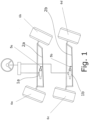
- the representation of the Fig. 1 shows an overview of the basic structure of an electromechanical dual-circuit steering system for commercial vehicles.
- This dual-circuit steering system has two steering systems 1a, b, specifically one steering system 1a, b for the front steering axle 2a and one for the rear steering axle 2b of the commercial vehicle.
- the direction selection element 3 of the commercial vehicle which is designed as a steering wheel and is electrically connected to the steering systems 1a, b in a manner not shown in detail here, the steering linkages 5a, b which connect the steering systems 1a, b to the respective steering axle 2a, b, and the wheels 6a, b, c, d.
- This structure applies to all of the exemplary embodiments described below. In each case, a single steering system 1a, b is used, although the other steering system 1a, b is designed identically.
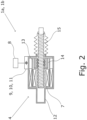
- the steering 1a with drive unit 4 is in the Fig. 2 , wherein the drive unit 4 is arranged in a substantially closed steering housing 12 of the steering system 1a.
- the electric motor 7 of this drive unit 4 is supplied with electrical energy during regular operation by the on-board electrical system as the main power supply 8.
- the steering system 1a has an energy storage device 11, designed as a capacitor 10, of an emergency power supply 9 for the electric motor 7, which emergency power supply 9 supplies the electric motor 7 in the event of a failure of the main power supply 8.
- the rotor 13 of the electric motor 7 forms, together with the spindle nut 14 and the threaded spindle 15, for actuating the respective steering linkage 5a, b.
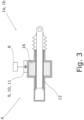
- the steering 1a with the drive unit 4 of the second embodiment is shown in the Fig. 3
- This second embodiment basically corresponds to the first embodiment, but here the electric motor 7 has a linear actuator 16 designed as a lifting magnet for actuating the respective steering linkage 5a, b.
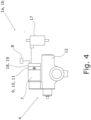
- the steering 1a is connected to the drive unit 4 of the third embodiment in the Fig. 4 reproduced.
- the emergency power supply 9 has both an energy storage device 11 designed as a capacitor 10 and a generator 17 arranged outside the steering housing. This generator is driven depending on the driving situation, supplies the electric motor 7, and charges the capacitor 10 acting as an intermediate storage device. In this way, the capacitor 10 is kept charged.
- This exemplary embodiment of the dual-circuit steering system further has a motor control module 18, to which a target steering angle is transmitted, which was detected by a sensor on the direction selection element 3. The motor control module 18 then controls the electric motor 7 according to the detected target steering angle. In this way, a steer-by-wire functionality is realized.
- the motor control module 18 also forms a data interface 19 for an autonomous driving control system, thus enabling driverless operation of the commercial vehicle.
Landscapes
- Engineering & Computer Science (AREA)
- Chemical & Material Sciences (AREA)
- Combustion & Propulsion (AREA)
- Transportation (AREA)
- Mechanical Engineering (AREA)
- Power Steering Mechanism (AREA)
- Steering Controls (AREA)
- Steering Control In Accordance With Driving Conditions (AREA)
Claims (14)
- Système de direction électromécanique double pour un véhicule utilitaire avec deux systèmes de direction (1a, b) comprenant respectivement une unité d'entraînement (4) pour l'actionnement d'une tringlerie de direction (5a, b) respective pour des roues (6a, b, c, d) du véhicule utilitaire, dans lequel chaque unité d'entraînement (4) présente un moteur électrique (7) respectif, dans lequel le système de direction double présente une alimentation en courant principale (8) pour l'alimentation des moteurs électriques (7) en énergie, caractérisé en ce que le système de direction double présente au moins une alimentation en courant d'urgence (9) pour l'alimentation d'un moteur électrique (7) de l'un système de direction (1a) en énergie en cas de panne de l'alimentation en courant principale (8), et l'autre système de direction (1b) est réglé de manière rigide.
- Système de direction électromécanique double selon la revendication 1, caractérisé en ce que le système de direction double comprend par moteur électrique (7) une alimentation en courant d'urgence (9) sensiblement autonome.
- Système de direction électromécanique double selon l'une quelconque des revendications 1 à 2, caractérisé en ce que l'alimentation en courant d'urgence (9) présente un générateur (17) qui est conçu afin d'être entraîné par un roulement du véhicule utilitaire et d'alimenter au moins l'un des moteurs électriques (7) en énergie.
- Système de direction électromécanique double selon l'une quelconque des revendications 1 à 3, caractérisé en ce que l'alimentation en courant d'urgence (9) présente un dispositif de stockage d'énergie (11) pour l'alimentation du moteur électrique (7).
- Système de direction électromécanique double selon la revendication 4, caractérisé en ce que l'alimentation en courant d'urgence (9) est conçue afin de charger le dispositif de stockage d'énergie (11) en cas de panne de l'alimentation en courant principale (8) par récupération de forces de rappel à partir de la tringlerie de direction (5a, b).
- Système de direction électromécanique double selon l'une quelconque des revendications 4 à 5, caractérisé en ce que le dispositif de stockage d'énergie (11) présente un accumulateur.
- Système de direction électromécanique double selon l'une quelconque des revendications 1 à 6, caractérisé en ce que chaque système de direction (1a, b) présente un propre boîtier de direction (12) sensiblement fermé, et l'alimentation en courant d'urgence (9) ainsi que l'unité d'entraînement (4) respective sont agencées dans au moins un boîtier de direction (12).
- Système de direction électromécanique double selon l'une quelconque des revendications 1 à 7, caractérisé en ce que le système de direction double présente une alimentation en courant d'urgence (9) pour l'alimentation de tous les moteurs électriques (7) en énergie en cas de panne de l'alimentation en courant principale (8).
- Système de direction électromécanique double selon l'une quelconque des revendications 1 à 8, caractérisé en ce que la force d'actionnement de la tringlerie de direction (5a, b) provient seulement du moteur électrique (7) respectif.
- Système de direction électromécanique double selon l'une quelconque des revendications 1 à 10, caractérisé en ce que le système de direction double comprend une interface de données (19) pour la commande du moteur électrique (7) par un système de commande de conduite autonome pour le fonctionnement sans conducteur du véhicule utilitaire.
- Système de direction électromécanique double selon l'une quelconque des revendications 1 à 10, caractérisé en ce que le système de direction double présente un capteur agencé au niveau d'un élément de commutation de direction du véhicule utilitaire, capteur qui détecte un angle de direction de consigne et le transmet à un module de commande de moteur (18) du système de direction double, module qui commande le moteur électrique (7) sur la base de l'angle de direction de consigne détecté.
- Système de direction électromécanique double selon l'une quelconque des revendications 1 à 11, caractérisé en ce que le moteur électrique (7) respectif comprend un actionneur linéaire (16) pour l'actionnement de la tringlerie de direction (5a, b).
- Système de direction électromécanique double selon l'une quelconque des revendications 1 à 12, caractérisé en ce que le moteur électrique (7) respectif présente un rotor (13) formé comme arbre creux, rotor qui est relié de manière immobile en rotation à un écrou de broche (14) de l'unité d'entraînement (4), lequel écrou de broche (14) est conçu afin d'entraîner une broche filetée (15) incorporée par l'unité d'entraînement (4) pour l'actionnement de la tringlerie de direction (5a, b).
- Véhicule utilitaire, caractérisé en ce qu'il présente un système de direction électromécanique double selon l'une quelconque des revendications 1 à 13.
Applications Claiming Priority (2)
| Application Number | Priority Date | Filing Date | Title |
|---|---|---|---|
| DE102020103150.5A DE102020103150A1 (de) | 2020-02-07 | 2020-02-07 | Elektromechanische Zweikreislenkung für ein Nutzfahrzeug |
| PCT/EP2021/051954 WO2021156132A1 (fr) | 2020-02-07 | 2021-01-28 | Système de direction électromécanique double pour un véhicule utilitaire |
Publications (2)
| Publication Number | Publication Date |
|---|---|
| EP4100298A1 EP4100298A1 (fr) | 2022-12-14 |
| EP4100298B1 true EP4100298B1 (fr) | 2025-06-25 |
Family
ID=74505214
Family Applications (1)
| Application Number | Title | Priority Date | Filing Date |
|---|---|---|---|
| EP21702916.4A Active EP4100298B1 (fr) | 2020-02-07 | 2021-01-28 | Système de direction électromécanique double pour un véhicule utilitaire |
Country Status (8)
| Country | Link |
|---|---|
| US (1) | US12448039B2 (fr) |
| EP (1) | EP4100298B1 (fr) |
| JP (1) | JP7443542B2 (fr) |
| CN (1) | CN115087582B (fr) |
| BR (1) | BR112022014157A2 (fr) |
| DE (1) | DE102020103150A1 (fr) |
| ES (1) | ES3036829T3 (fr) |
| WO (1) | WO2021156132A1 (fr) |
Families Citing this family (3)
| Publication number | Priority date | Publication date | Assignee | Title |
|---|---|---|---|---|
| EP3947110B1 (fr) * | 2019-04-05 | 2025-07-30 | Oshkosh Corporation | Systèmes d'orientation en élévation et procédés |
| DE102024103411A1 (de) * | 2024-02-07 | 2025-08-07 | Knorr-Bremse Systeme für Nutzfahrzeuge GmbH | Lenksystem |
| DE102024103412A1 (de) * | 2024-02-07 | 2025-08-07 | Knorr-Bremse Systeme für Nutzfahrzeuge GmbH | Sekundärlenkvorrichtung |
Family Cites Families (25)
| Publication number | Priority date | Publication date | Assignee | Title |
|---|---|---|---|---|
| JPH0717203B2 (ja) * | 1986-03-20 | 1995-03-01 | マツダ株式会社 | 車両の4輪操舵装置 |
| US4960178A (en) * | 1987-09-30 | 1990-10-02 | Hitachi, Ltd. | Motor-driven power steering apparatus |
| JPH0526732U (ja) * | 1991-09-11 | 1993-04-06 | 三菱自動車工業株式会社 | 四輪操舵車両 |
| JPH07172332A (ja) * | 1992-12-04 | 1995-07-11 | Aisin Seiki Co Ltd | 後輪操舵装置 |
| DE19910001B4 (de) | 1999-03-08 | 2008-04-17 | Zf Friedrichshafen Ag | Zweikreis-Lenkanlage für Mobilfahrzeuge |
| JP2003343682A (ja) | 2002-05-29 | 2003-12-03 | Ntn Corp | ボールねじおよびそれを具備する電動パワーステアリング装置 |
| DE502006007588D1 (de) | 2005-05-02 | 2010-09-16 | Continental Teves Ag & Co Ohg | Lenkvorrichtung, insbesondere für eine hinterachslenkung |
| JP4297149B2 (ja) * | 2006-09-29 | 2009-07-15 | トヨタ自動車株式会社 | 車両の操舵装置 |
| JP2009096213A (ja) | 2007-10-12 | 2009-05-07 | Jtekt Corp | 電動パワーステアリング装置 |
| JP2009120097A (ja) | 2007-11-16 | 2009-06-04 | Jtekt Corp | ステアリング装置の制御装置 |
| DE102008022606A1 (de) * | 2008-05-08 | 2009-11-12 | Man Nutzfahrzeuge Aktiengesellschaft | Spurführungssystem |
| US8069945B2 (en) * | 2008-08-26 | 2011-12-06 | Trw Automotive U.S. Llc | Method and apparatus for rear wheel steering control |
| JP5293088B2 (ja) | 2008-10-29 | 2013-09-18 | トヨタ自動車株式会社 | 車両の操舵装置 |
| US8360197B2 (en) | 2011-03-23 | 2013-01-29 | GM Global Technology Operations LLC | Recirculating ball power steering system |
| DE102012212608A1 (de) | 2012-07-18 | 2014-02-06 | Schaeffler Technologies AG & Co. KG | Aktuator für eine elektronisch gesteuerte elektromechanische Lenkung für schwere Nutzfahrzeuge |
| DE102013000898A1 (de) | 2013-01-18 | 2014-07-24 | Volkswagen Aktiengesellschaft | Lenkhilfeeinrichtung mit Motor und Vorrichtung zur Lagesensierung |
| US9238481B2 (en) * | 2013-03-15 | 2016-01-19 | Trw Automotive U.S. Llc | Steering system for turning multiple sets of steerable wheels |
| CN103552606B (zh) | 2013-10-22 | 2016-03-23 | 安徽安凯汽车股份有限公司 | 一种中型纯电动客车底盘 |
| DE102015201032B4 (de) * | 2015-01-22 | 2018-12-20 | Volkswagen Aktiengesellschaft | Lenksystem für ein automatisiertes Fahren eines Kraftfahrzeuges |
| US10501113B2 (en) * | 2016-05-13 | 2019-12-10 | Nsk Ltd. | Motor drive control device, electric power steering device, and vehicle |
| DE102017205666B4 (de) * | 2016-05-25 | 2024-06-27 | Zf Friedrichshafen Ag | Lenkung mit einer Stelleinrichtung sowie Verwendung der Lenkung mit Stelleinrichtung |
| JP6709130B2 (ja) * | 2016-08-24 | 2020-06-10 | 本田技研工業株式会社 | 車両用操舵装置 |
| DE102017104667A1 (de) | 2017-03-06 | 2018-09-06 | Knorr-Bremse Systeme für Nutzfahrzeuge GmbH | Stromversorgungseinheit für ein Nutzfahrzeug und Verfahren zum Betreiben einer Stromversorgungseinheit für ein Nutzfahrzeug |
| DE102017108378B4 (de) | 2017-04-20 | 2020-04-23 | Saf-Holland Gmbh | Lenkeinrichtung für ein Achsaggregat, Achsaggregat mit einer Lenkeinrichtung und Verfahren zum Lenken eines Fahrzeugs |
| JP6801593B2 (ja) | 2017-06-14 | 2020-12-16 | 株式会社デンソー | 車両の操舵支援装置および操舵支援制御方法 |
-
2020
- 2020-02-07 DE DE102020103150.5A patent/DE102020103150A1/de active Pending
-
2021
- 2021-01-28 BR BR112022014157A patent/BR112022014157A2/pt unknown
- 2021-01-28 WO PCT/EP2021/051954 patent/WO2021156132A1/fr not_active Ceased
- 2021-01-28 JP JP2022547975A patent/JP7443542B2/ja active Active
- 2021-01-28 US US17/797,963 patent/US12448039B2/en active Active
- 2021-01-28 CN CN202180013445.1A patent/CN115087582B/zh active Active
- 2021-01-28 EP EP21702916.4A patent/EP4100298B1/fr active Active
- 2021-01-28 ES ES21702916T patent/ES3036829T3/es active Active
Also Published As
| Publication number | Publication date |
|---|---|
| DE102020103150A1 (de) | 2021-08-12 |
| JP7443542B2 (ja) | 2024-03-05 |
| WO2021156132A1 (fr) | 2021-08-12 |
| US20230043320A1 (en) | 2023-02-09 |
| JP2023512813A (ja) | 2023-03-29 |
| EP4100298A1 (fr) | 2022-12-14 |
| CN115087582B (zh) | 2024-02-23 |
| CN115087582A (zh) | 2022-09-20 |
| US12448039B2 (en) | 2025-10-21 |
| ES3036829T3 (en) | 2025-09-24 |
| BR112022014157A2 (pt) | 2022-09-13 |
Similar Documents
| Publication | Publication Date | Title |
|---|---|---|
| EP1268257B1 (fr) | Direction de vehicule et module de direction pour direction de vehicule | |
| EP3022107B1 (fr) | Procédé permettant de faire fonctionner la direction d'un véhicule automobile | |
| DE60221949T2 (de) | Elektrische Lenkung für ein Fahrzeug mit dreifacher Redundanz | |
| DE60127462T2 (de) | Federbein, versehen mit Antriebsmitteln | |
| EP4100298B1 (fr) | Système de direction électromécanique double pour un véhicule utilitaire | |
| DE102014004231A1 (de) | Lenkvorrichtung | |
| DE102016006088A1 (de) | Steer-by-Wire-Lenksystem mit kuppelbaren Einzelradlenkungen | |
| DE10101827A1 (de) | Lenkanordnung für Kraftfahrzeuge | |
| DE102013004171A1 (de) | Elektrische Servolenkungsvorrichtung für ein Fahrzeug | |
| DE102019104391A1 (de) | Kraftfahrzeug und Verfahren zu dessen Steuerung | |
| DE102018119977A1 (de) | Lenkgetriebe für ein Steer-by-Wire-Lenksystem | |
| DE102022104584A1 (de) | Lenksystem und lenkbare Achse für ein Kraftfahrzeug | |
| EP4273025A1 (fr) | Système de direction à commande par câble et procédé permettant de faire fonctionner un système de direction à commande par câble dans un mode de fonctionnement normal et dans un mode de fonctionnement spécial | |
| EP1998427B1 (fr) | Installation de frein d'un véhicule automobile doté d'un frein de récupération électrique | |
| EP3511226A1 (fr) | Système d'entraînement électrique et procédé de fonctionnement d'un système d'entraînement électrique | |
| DE102018214473B4 (de) | Lenkvorrichtung für ein Kraftfahrzeug, insbesondere für einen Personenkraftwagen, sowie Kraftfahrzeug, insbesondere Personenkraftwagen, mit einer solchen Lenkvorrichtung | |
| WO2020244909A1 (fr) | Procédé de fonctionnement d'un système de direction à commande électrique | |
| EP4568871A1 (fr) | Procédé de fonctionnement d'un véhicule automobile, en particulier d'un véhicule automobile de tourisme, et véhicules automobiles | |
| DE102024110539B4 (de) | Hybrides Steer-by-Wire-System | |
| EP3653469A1 (fr) | Dispositif de direction d'un véhicule | |
| DE102007000939A1 (de) | Elektrische Hilfskraftlenkung | |
| DE102024103412A1 (de) | Sekundärlenkvorrichtung | |
| DE102024103411A1 (de) | Lenksystem | |
| WO2024132269A1 (fr) | Système de direction pour un véhicule automobile et procédé associé | |
| DE102017204768B4 (de) | Kraftfahrzeug |
Legal Events
| Date | Code | Title | Description |
|---|---|---|---|
| STAA | Information on the status of an ep patent application or granted ep patent |
Free format text: STATUS: UNKNOWN |
|
| STAA | Information on the status of an ep patent application or granted ep patent |
Free format text: STATUS: THE INTERNATIONAL PUBLICATION HAS BEEN MADE |
|
| PUAI | Public reference made under article 153(3) epc to a published international application that has entered the european phase |
Free format text: ORIGINAL CODE: 0009012 |
|
| STAA | Information on the status of an ep patent application or granted ep patent |
Free format text: STATUS: REQUEST FOR EXAMINATION WAS MADE |
|
| 17P | Request for examination filed |
Effective date: 20220907 |
|
| AK | Designated contracting states |
Kind code of ref document: A1 Designated state(s): AL AT BE BG CH CY CZ DE DK EE ES FI FR GB GR HR HU IE IS IT LI LT LU LV MC MK MT NL NO PL PT RO RS SE SI SK SM TR |
|
| DAV | Request for validation of the european patent (deleted) | ||
| DAX | Request for extension of the european patent (deleted) | ||
| RAP3 | Party data changed (applicant data changed or rights of an application transferred) |
Owner name: KNORR-BREMSE SYSTEME FUER NUTZFAHRZEUGE GMBH |
|
| GRAP | Despatch of communication of intention to grant a patent |
Free format text: ORIGINAL CODE: EPIDOSNIGR1 |
|
| STAA | Information on the status of an ep patent application or granted ep patent |
Free format text: STATUS: GRANT OF PATENT IS INTENDED |
|
| INTG | Intention to grant announced |
Effective date: 20250224 |
|
| P01 | Opt-out of the competence of the unified patent court (upc) registered |
Free format text: CASE NUMBER: APP_12539/2025 Effective date: 20250313 |
|
| GRAS | Grant fee paid |
Free format text: ORIGINAL CODE: EPIDOSNIGR3 |
|
| GRAA | (expected) grant |
Free format text: ORIGINAL CODE: 0009210 |
|
| STAA | Information on the status of an ep patent application or granted ep patent |
Free format text: STATUS: THE PATENT HAS BEEN GRANTED |
|
| AK | Designated contracting states |
Kind code of ref document: B1 Designated state(s): AL AT BE BG CH CY CZ DE DK EE ES FI FR GB GR HR HU IE IS IT LI LT LU LV MC MK MT NL NO PL PT RO RS SE SI SK SM TR |
|
| REG | Reference to a national code |
Ref country code: GB Ref legal event code: FG4D Free format text: NOT ENGLISH |
|
| REG | Reference to a national code |
Ref country code: CH Ref legal event code: EP |
|
| REG | Reference to a national code |
Ref country code: DE Ref legal event code: R096 Ref document number: 502021007840 Country of ref document: DE |
|
| REG | Reference to a national code |
Ref country code: CH Ref legal event code: EP |
|
| REG | Reference to a national code |
Ref country code: IE Ref legal event code: FG4D Free format text: LANGUAGE OF EP DOCUMENT: GERMAN |
|
| REG | Reference to a national code |
Ref country code: SE Ref legal event code: TRGR |
|
| REG | Reference to a national code |
Ref country code: NL Ref legal event code: FP |
|
| REG | Reference to a national code |
Ref country code: ES Ref legal event code: FG2A Ref document number: 3036829 Country of ref document: ES Kind code of ref document: T3 Effective date: 20250924 |
|
| PG25 | Lapsed in a contracting state [announced via postgrant information from national office to epo] |
Ref country code: FI Free format text: LAPSE BECAUSE OF FAILURE TO SUBMIT A TRANSLATION OF THE DESCRIPTION OR TO PAY THE FEE WITHIN THE PRESCRIBED TIME-LIMIT Effective date: 20250625 |
|
| REG | Reference to a national code |
Ref country code: LT Ref legal event code: MG9D |
|
| PG25 | Lapsed in a contracting state [announced via postgrant information from national office to epo] |
Ref country code: NO Free format text: LAPSE BECAUSE OF FAILURE TO SUBMIT A TRANSLATION OF THE DESCRIPTION OR TO PAY THE FEE WITHIN THE PRESCRIBED TIME-LIMIT Effective date: 20250925 Ref country code: GR Free format text: LAPSE BECAUSE OF FAILURE TO SUBMIT A TRANSLATION OF THE DESCRIPTION OR TO PAY THE FEE WITHIN THE PRESCRIBED TIME-LIMIT Effective date: 20250926 |
|
| PG25 | Lapsed in a contracting state [announced via postgrant information from national office to epo] |
Ref country code: BG Free format text: LAPSE BECAUSE OF FAILURE TO SUBMIT A TRANSLATION OF THE DESCRIPTION OR TO PAY THE FEE WITHIN THE PRESCRIBED TIME-LIMIT Effective date: 20250625 |
|
| PG25 | Lapsed in a contracting state [announced via postgrant information from national office to epo] |
Ref country code: HR Free format text: LAPSE BECAUSE OF FAILURE TO SUBMIT A TRANSLATION OF THE DESCRIPTION OR TO PAY THE FEE WITHIN THE PRESCRIBED TIME-LIMIT Effective date: 20250625 |
|
| PG25 | Lapsed in a contracting state [announced via postgrant information from national office to epo] |
Ref country code: RS Free format text: LAPSE BECAUSE OF FAILURE TO SUBMIT A TRANSLATION OF THE DESCRIPTION OR TO PAY THE FEE WITHIN THE PRESCRIBED TIME-LIMIT Effective date: 20250925 |
|
| PG25 | Lapsed in a contracting state [announced via postgrant information from national office to epo] |
Ref country code: LV Free format text: LAPSE BECAUSE OF FAILURE TO SUBMIT A TRANSLATION OF THE DESCRIPTION OR TO PAY THE FEE WITHIN THE PRESCRIBED TIME-LIMIT Effective date: 20250625 |
|
| PG25 | Lapsed in a contracting state [announced via postgrant information from national office to epo] |
Ref country code: PT Free format text: LAPSE BECAUSE OF FAILURE TO SUBMIT A TRANSLATION OF THE DESCRIPTION OR TO PAY THE FEE WITHIN THE PRESCRIBED TIME-LIMIT Effective date: 20251027 |