EP4100275B1 - Anordnung und verfahren zur durchführung eines selbstlasttests bei einem schienenfahrzeug - Google Patents
Anordnung und verfahren zur durchführung eines selbstlasttests bei einem schienenfahrzeug Download PDFInfo
- Publication number
- EP4100275B1 EP4100275B1 EP21712965.9A EP21712965A EP4100275B1 EP 4100275 B1 EP4100275 B1 EP 4100275B1 EP 21712965 A EP21712965 A EP 21712965A EP 4100275 B1 EP4100275 B1 EP 4100275B1
- Authority
- EP
- European Patent Office
- Prior art keywords
- converter
- line system
- link
- hspl
- power
- Prior art date
- Legal status (The legal status is an assumption and is not a legal conclusion. Google has not performed a legal analysis and makes no representation as to the accuracy of the status listed.)
- Active
Links
Images


Classifications
-
- G—PHYSICS
- G01—MEASURING; TESTING
- G01M—TESTING STATIC OR DYNAMIC BALANCE OF MACHINES OR STRUCTURES; TESTING OF STRUCTURES OR APPARATUS, NOT OTHERWISE PROVIDED FOR
- G01M17/00—Testing of vehicles
- G01M17/08—Railway vehicles
-
- B—PERFORMING OPERATIONS; TRANSPORTING
- B60—VEHICLES IN GENERAL
- B60L—PROPULSION OF ELECTRICALLY-PROPELLED VEHICLES; SUPPLYING ELECTRIC POWER FOR AUXILIARY EQUIPMENT OF ELECTRICALLY-PROPELLED VEHICLES; ELECTRODYNAMIC BRAKE SYSTEMS FOR VEHICLES IN GENERAL; MAGNETIC SUSPENSION OR LEVITATION FOR VEHICLES; MONITORING OPERATING VARIABLES OF ELECTRICALLY-PROPELLED VEHICLES; ELECTRIC SAFETY DEVICES FOR ELECTRICALLY-PROPELLED VEHICLES
- B60L9/00—Electric propulsion with power supply external to the vehicle
- B60L9/16—Electric propulsion with power supply external to the vehicle using AC induction motors
- B60L9/24—Electric propulsion with power supply external to the vehicle using AC induction motors fed from AC supply lines
- B60L9/28—Electric propulsion with power supply external to the vehicle using AC induction motors fed from AC supply lines polyphase motors
-
- B—PERFORMING OPERATIONS; TRANSPORTING
- B60—VEHICLES IN GENERAL
- B60L—PROPULSION OF ELECTRICALLY-PROPELLED VEHICLES; SUPPLYING ELECTRIC POWER FOR AUXILIARY EQUIPMENT OF ELECTRICALLY-PROPELLED VEHICLES; ELECTRODYNAMIC BRAKE SYSTEMS FOR VEHICLES IN GENERAL; MAGNETIC SUSPENSION OR LEVITATION FOR VEHICLES; MONITORING OPERATING VARIABLES OF ELECTRICALLY-PROPELLED VEHICLES; ELECTRIC SAFETY DEVICES FOR ELECTRICALLY-PROPELLED VEHICLES
- B60L50/00—Electric propulsion with power supplied within the vehicle
- B60L50/10—Electric propulsion with power supplied within the vehicle using propulsion power supplied by engine-driven generators, e.g. generators driven by combustion engines
- B60L50/13—Electric propulsion with power supplied within the vehicle using propulsion power supplied by engine-driven generators, e.g. generators driven by combustion engines using AC generators and AC motors
-
- B—PERFORMING OPERATIONS; TRANSPORTING
- B60—VEHICLES IN GENERAL
- B60L—PROPULSION OF ELECTRICALLY-PROPELLED VEHICLES; SUPPLYING ELECTRIC POWER FOR AUXILIARY EQUIPMENT OF ELECTRICALLY-PROPELLED VEHICLES; ELECTRODYNAMIC BRAKE SYSTEMS FOR VEHICLES IN GENERAL; MAGNETIC SUSPENSION OR LEVITATION FOR VEHICLES; MONITORING OPERATING VARIABLES OF ELECTRICALLY-PROPELLED VEHICLES; ELECTRIC SAFETY DEVICES FOR ELECTRICALLY-PROPELLED VEHICLES
- B60L50/00—Electric propulsion with power supplied within the vehicle
- B60L50/10—Electric propulsion with power supplied within the vehicle using propulsion power supplied by engine-driven generators, e.g. generators driven by combustion engines
- B60L50/15—Electric propulsion with power supplied within the vehicle using propulsion power supplied by engine-driven generators, e.g. generators driven by combustion engines with additional electric power supply
-
- B—PERFORMING OPERATIONS; TRANSPORTING
- B60—VEHICLES IN GENERAL
- B60M—POWER SUPPLY LINES, AND DEVICES ALONG RAILS, FOR ELECTRICALLY- PROPELLED VEHICLES
- B60M3/00—Feeding power to supply lines in contact with collector on vehicles; Arrangements for consuming regenerative power
- B60M3/06—Arrangements for consuming regenerative power
-
- B—PERFORMING OPERATIONS; TRANSPORTING
- B61—RAILWAYS
- B61L—GUIDING RAILWAY TRAFFIC; ENSURING THE SAFETY OF RAILWAY TRAFFIC
- B61L15/00—Indicators provided on the vehicle or train for signalling purposes
- B61L15/0081—On-board diagnosis or maintenance
-
- B—PERFORMING OPERATIONS; TRANSPORTING
- B60—VEHICLES IN GENERAL
- B60L—PROPULSION OF ELECTRICALLY-PROPELLED VEHICLES; SUPPLYING ELECTRIC POWER FOR AUXILIARY EQUIPMENT OF ELECTRICALLY-PROPELLED VEHICLES; ELECTRODYNAMIC BRAKE SYSTEMS FOR VEHICLES IN GENERAL; MAGNETIC SUSPENSION OR LEVITATION FOR VEHICLES; MONITORING OPERATING VARIABLES OF ELECTRICALLY-PROPELLED VEHICLES; ELECTRIC SAFETY DEVICES FOR ELECTRICALLY-PROPELLED VEHICLES
- B60L2200/00—Type of vehicles
- B60L2200/26—Rail vehicles
Definitions
- a second drive system is based on operation of the rail vehicle on the contact wire. Electrical energy or power is taken from the contact wire via a pantograph, converted and fed to the electric drive motors of the rail vehicle for locomotion.
- the diesel engine is subjected to a load which, in the maximum case, corresponds to the rated load of the diesel engine. This is referred to as the "diesel engine self-load test” or "self-load test”.
- This test can be carried out by the customer using a separate diesel engine test, in which the diesel engine is mounted on a special Test stand is connected to a so-called load machine and operated under a corresponding load or load.
- the performance of the diesel engine is fed to the braking resistor by using a drive chain of the locomotive via the main generator with a downstream converter and braking unit when stationary.
- the power or energy generated during the self-test is converted into heat in an installed braking resistor.
- FIG. 3 shows as an example of a rail vehicle components of a diesel-electric locomotive LOK3 and their use in the self-load test according to the prior art.
- a second DC/AC converter GSWSW2 forms AC voltage for a third drive motor MOT3 and for a fourth drive motor MOT4 of the rail vehicle or locomotive.
- a third DC-AC converter GSWSW3 forms AC voltage for auxiliary drives (e.g. compressor, ventilation, etc.) or for other uses referred to as AUX in the rail vehicle or in the locomotive.
- auxiliary drives e.g. compressor, ventilation, etc.
- the AC-DC converter WSGSW1 is also connected on the output side to inputs of a DC-DC converter GSGSW, which is also connected in parallel with the three DC-AC converters GSWSW1 to GSWSW3, so that the AC-DC converter WSGSW1 educated DC voltage is present at the inputs of the DC-DC converter GSGSW.
- the two resistors RBR, RLOAD convert the electrical power supplied to them into heat.
- Another drive system is provided here. This is based on electrical operation of the rail vehicle using an overhead line and a pantograph or pantograph PANT.
- the pantograph PANT takes electrical power or energy from the overhead line, which is designed here as a high-voltage line HSPL, for example, and supplies it to a transformer TR via a main switch HS.
- HSPL high-voltage line
- the AC-DC converter WSGSW2 forms a DC voltage from the AC voltage supplied to it, which reaches the inputs of the three DC-AC converters GSWSW1 to GSWSW3 and the inputs of the DC-DC converter GSGSW.
- the invention relates to an arrangement and method for carrying out a self-load test with a rail vehicle that has a dual-mode drive system.
- a first propulsion system of the rail vehicle includes a diesel engine coupled to an electrical generator to generate electrical power.
- the generator On the output side, the generator is connected to a DC voltage intermediate circuit via a first converter connected downstream of it, so that the power supplied by the generator can be transmitted to the DC voltage intermediate circuit via the first converter if required.
- the second drive system of the rail vehicle has an electrical line system, which is connected to the DC voltage intermediate circuit via a second converter connected downstream of it, so that power can be transmitted from the line system to the DC voltage intermediate circuit if required.
- the generator, the first converter, the DC voltage intermediate circuit, the second converter and the line system are connected in such a way that the power supplied by the generator during the self-load test of the diesel engine reaches the second converter at least partially via the first converter and via the DC voltage intermediate circuit and that the power supplied to the second converter is fed into the line system.
- the intermediate DC circuit is connected via a third converter to a braking resistor, which is arranged inside the rail vehicle.
- the third converter can be controlled in such a way that power that is no longer required during braking is supplied from the DC voltage intermediate circuit to the braking resistor.
- the braking resistor is dimensioned in such a way that it converts the power supplied to it into heat.
- the third converter can be controlled in such a way that a first part of the power generated by the diesel engine, which reaches the DC link via the first converter, is fed from there to the braking resistor via the third converter.
- the second converter can be controlled in such a way that a second part of the power generated by the diesel engine, which reaches the DC link via the first converter, is fed from there to the line system via the second converter.
- the line system is designed as an overhead line system or as a line system close to the rails.
- the line system is designed as a line system based on direct current or as a line system based on alternating current.
- At least one electric motor which as the drive motor of the rail vehicle is coupled to a wheel of the rail vehicle, is connected to the intermediate DC circuit via a further converter.
- This converter is designed as a DC/AC converter and is connected in such a way that power is transmitted from the DC link to the drive motor.
- the arrangement according to the invention results in lower energy costs for the operator of the dual-mode rail vehicle, since rail vehicles or locomotives are equipped with energy meters that positively take energy feedback into account in the energy balance.
- the arrangement according to the invention enables the operator to carry out a comprehensive self-load test even in the case of a low-capacity overhead line network.
- part of the energy supplied by the diesel engine can be fed into the overhead line network if the operator does not have an external power resistor available.
- the invention is defined by the software of the vehicle control. This fulfills the following tasks: The vehicle is put into "self-load test” mode, which safely disables the drive inverters and the locomotive remains stationary.
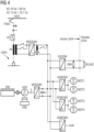
- FIG 1 shows a first embodiment of the arrangement according to the invention for self-load testing in a dual-mode locomotive LOK1.
- a first drive system is realized via a diesel engine DM.
- the diesel engine DM is operated as an internal combustion engine and is mechanically connected to a generator GEN via a clutch.
- the generator GEN is driven mechanically via the diesel engine DM, with the generator GEN being coupled to an exciter ERG in order to generate electrical power.
- an AC/DC converter WSGSW1 which forms a DC voltage from the AC voltage supplied.
- the AC/DC converter is WSGSW1 a capacitor C connected in parallel or provided on the output side.
- the three DC-AC voltage converters GSWSW1 to GSWSW3 form respective AC voltages from the supplied DC voltage for further use.
- a first DC/AC converter GSWSW1 forms AC voltage for a first drive motor MOT1 and for a second drive motor MOT2 of the rail vehicle or locomotive.
- a third DC-AC converter GSWSW3 forms AC voltage for the auxiliary drives (e.g. compressor, ventilation, etc.) or for other uses designated as AUX in rail vehicles or locomotives.
- the pantograph PANT draws electrical power or energy from an overhead line or high-voltage line HSPL feeds them to a transformer TR via a main switch HS.
- a first portion E1 of the power reaches the braking resistor RBR, which is arranged in the rail vehicle or in the locomotive, via the DC voltage-DC voltage converter GSGSW is.
- the braking resistor RBR converts the partial electrical power E1 supplied to it into heat.
Landscapes
- Engineering & Computer Science (AREA)
- Mechanical Engineering (AREA)
- Power Engineering (AREA)
- Transportation (AREA)
- Health & Medical Sciences (AREA)
- General Physics & Mathematics (AREA)
- Physics & Mathematics (AREA)
- Biomedical Technology (AREA)
- General Health & Medical Sciences (AREA)
- Life Sciences & Earth Sciences (AREA)
- Sustainable Development (AREA)
- Sustainable Energy (AREA)
- Electric Propulsion And Braking For Vehicles (AREA)
- Vehicle Body Suspensions (AREA)
Applications Claiming Priority (2)
| Application Number | Priority Date | Filing Date | Title |
|---|---|---|---|
| DE102020205179 | 2020-04-23 | ||
| PCT/EP2021/055524 WO2021213724A1 (de) | 2020-04-23 | 2021-03-04 | Anordnung und verfahren zur durchführung eines selbstlasttests bei einem schienenfahrzeug |
Publications (2)
| Publication Number | Publication Date |
|---|---|
| EP4100275A1 EP4100275A1 (de) | 2022-12-14 |
| EP4100275B1 true EP4100275B1 (de) | 2023-07-12 |
Family
ID=75108304
Family Applications (1)
| Application Number | Title | Priority Date | Filing Date |
|---|---|---|---|
| EP21712965.9A Active EP4100275B1 (de) | 2020-04-23 | 2021-03-04 | Anordnung und verfahren zur durchführung eines selbstlasttests bei einem schienenfahrzeug |
Country Status (6)
| Country | Link |
|---|---|
| US (1) | US12163862B2 (pl) |
| EP (1) | EP4100275B1 (pl) |
| CN (1) | CN115427252A (pl) |
| ES (1) | ES2952670T3 (pl) |
| PL (1) | PL4100275T3 (pl) |
| WO (1) | WO2021213724A1 (pl) |
Citations (1)
| Publication number | Priority date | Publication date | Assignee | Title |
|---|---|---|---|---|
| EP1186497B1 (de) * | 2000-09-12 | 2006-03-29 | ALSTOM LHB GmbH | Schienentriebfahrzeug mit Energieversorgungssystem |
Family Cites Families (16)
| Publication number | Priority date | Publication date | Assignee | Title |
|---|---|---|---|---|
| GB1351563A (en) * | 1972-03-29 | 1974-05-01 | Mo I Inzhenerov Zheleznodorozh | Electrical energy conservation during testing of a prime-mover- electrical generator unit |
| DE9415770U1 (de) | 1994-09-30 | 1994-12-15 | ABB Henschel AG, 13509 Berlin | Schienengebundenes Dieseltriebfahrzeug |
| US20060005739A1 (en) * | 2001-03-27 | 2006-01-12 | Kumar Ajith K | Railroad system comprising railroad vehicle with energy regeneration |
| US7344202B2 (en) * | 2005-05-11 | 2008-03-18 | General Electric Company | System and method for dealing with ground fault conditions that can arise in an electrical propulsion system |
| DE102006010536B4 (de) * | 2006-03-07 | 2008-06-12 | Siemens Ag | Dieselelektrisches Antriebssystem mit einem permanent erregten Synchrongenerator |
| DE102007003172B4 (de) * | 2006-08-08 | 2011-06-01 | Siemens Ag | Dieselelektrisches Antriebssystem |
| WO2008144901A1 (en) * | 2007-05-25 | 2008-12-04 | Railpower Technologies Corp. | Power architecture and braking circuits for dc motor-propelled vehicle |
| DE102008023332B4 (de) | 2008-05-13 | 2010-12-02 | Siemens Aktiengesellschaft | Dieselelektrisches Antriebssystem |
| US9415781B2 (en) * | 2008-12-23 | 2016-08-16 | Progress Rail Services Corporation | Dual engine locomotive |
| US9784194B2 (en) * | 2014-06-30 | 2017-10-10 | General Electric Company | Systems for a multi-fuel capable engine |
| JP5295470B1 (ja) | 2012-01-30 | 2013-09-18 | 三菱電機株式会社 | 電気車の推進制御装置およびその制御方法 |
| US9008879B2 (en) * | 2012-07-05 | 2015-04-14 | General Electric Company | System and method for operating a hybrid vehicle system |
| CN202847693U (zh) * | 2012-10-30 | 2013-04-03 | 株洲南车时代电气股份有限公司 | 一种交流传动机车电气牵引系统 |
| JP6974913B2 (ja) * | 2016-11-30 | 2021-12-01 | 株式会社辰巳菱機 | 負荷試験システム |
| CN110077240A (zh) * | 2019-05-17 | 2019-08-02 | 中车资阳机车有限公司 | 一种多动力源交流传动机车电路拓扑结构 |
| CN110406549B (zh) | 2019-09-04 | 2024-03-01 | 宝鸡中车时代工程机械有限公司 | 一种利用柴油机和动力蓄电池牵引的混合动力轨道车 |
-
2021
- 2021-03-04 PL PL21712965.9T patent/PL4100275T3/pl unknown
- 2021-03-04 WO PCT/EP2021/055524 patent/WO2021213724A1/de not_active Ceased
- 2021-03-04 US US17/920,873 patent/US12163862B2/en active Active
- 2021-03-04 EP EP21712965.9A patent/EP4100275B1/de active Active
- 2021-03-04 ES ES21712965T patent/ES2952670T3/es active Active
- 2021-03-04 CN CN202180029754.8A patent/CN115427252A/zh active Pending
Patent Citations (1)
| Publication number | Priority date | Publication date | Assignee | Title |
|---|---|---|---|---|
| EP1186497B1 (de) * | 2000-09-12 | 2006-03-29 | ALSTOM LHB GmbH | Schienentriebfahrzeug mit Energieversorgungssystem |
Also Published As
| Publication number | Publication date |
|---|---|
| US20230184632A1 (en) | 2023-06-15 |
| CN115427252A (zh) | 2022-12-02 |
| ES2952670T3 (es) | 2023-11-03 |
| EP4100275A1 (de) | 2022-12-14 |
| PL4100275T3 (pl) | 2023-11-27 |
| US12163862B2 (en) | 2024-12-10 |
| WO2021213724A1 (de) | 2021-10-28 |
Similar Documents
| Publication | Publication Date | Title |
|---|---|---|
| DE112013006718B4 (de) | Antriebssteuervorrichtung für Schienenfahrzeug | |
| EP2229291B1 (de) | Anordnung zur versorgung von einrichtungen einer lokomotive mit elektrischer energie und verfahren zum betreiben der anordnung | |
| DE102010028972B4 (de) | Motorantriebssystem für ein Hybridfahrzeug und Verfahren zum Steuern desselben | |
| DE102018100472B4 (de) | Elektrisches antriebssystem für elektrisches fahrzeug | |
| EP2277259B1 (de) | Dieselelektrisches antriebssystem | |
| EP2822802B1 (de) | Vorrichtung für ein elektrisch angetriebenes schienenfahrzeug | |
| WO2013159821A1 (de) | Ladeeinrichtung | |
| WO2013159887A1 (de) | Kraftwagen mit einem hochvolt-energieversorgungssystem | |
| DE102017210750A1 (de) | Bordnetz für ein Schienenfahrzeug, Verfahren zum Betreiben des Bordnetzes und Schienenfahrzeug | |
| DE102012208241A1 (de) | Schienenfahrzeugsschaltungsanordnung | |
| EP4100275B1 (de) | Anordnung und verfahren zur durchführung eines selbstlasttests bei einem schienenfahrzeug | |
| DE102022201132A1 (de) | Ladegerät für ein elektrisch angetriebenes Fahrzeug und Verfahren zum Betrieb eines Ladegerätes für ein elektrisch angetriebenes Fahrzeug | |
| DE102016204701B4 (de) | Fahrzeugantriebssystem | |
| DE19908495B4 (de) | Von einem AC-Fahrdraht versorgte, tranformatorlose Einspeiseschaltung für eine Wechselstrommaschine eines Bahnfahrzeuges | |
| EP4201784B1 (de) | Anordnung zum antrieb einer lokomotive mit unterschiedlichen energiebereitstellungssystemen | |
| EP3867620B1 (de) | Rollenprüfstand und verfahren zum betreiben eines rollenprüfstands | |
| AT521412A1 (de) | Schienenfahrzeug | |
| WO2022037800A1 (de) | Dual-mode-lokomotive | |
| EP3184349A1 (de) | Energieversorgungssystem für ein fahrzeug und fahrzeug elektrischem traktionssystem | |
| DE102021130987A1 (de) | Elektrisches Antriebssystem für eine Arbeitsmaschine mit zwei unabhängig voneinander regelbaren Elektromotoren | |
| EP2670042B1 (de) | Stromrichter mit redundanter Zwischenkreisspannungsmessung, sowie Verfahren zum Betreiben eines Stromrichters | |
| EP3736168A1 (de) | Antriebssystem für ein diesel-elektrisches fahrzeug | |
| AT523185B1 (de) | Prüfstand für den Antrieb eines Fahrzeugs | |
| EP4197847A1 (de) | Verfahren zum betreiben eines fahrzeugs | |
| DE19641630C1 (de) | Einspeiseschaltung für ein Schienen-Triebfahrzeug |
Legal Events
| Date | Code | Title | Description |
|---|---|---|---|
| STAA | Information on the status of an ep patent application or granted ep patent |
Free format text: STATUS: UNKNOWN |
|
| STAA | Information on the status of an ep patent application or granted ep patent |
Free format text: STATUS: THE INTERNATIONAL PUBLICATION HAS BEEN MADE |
|
| PUAI | Public reference made under article 153(3) epc to a published international application that has entered the european phase |
Free format text: ORIGINAL CODE: 0009012 |
|
| STAA | Information on the status of an ep patent application or granted ep patent |
Free format text: STATUS: REQUEST FOR EXAMINATION WAS MADE |
|
| 17P | Request for examination filed |
Effective date: 20220909 |
|
| AK | Designated contracting states |
Kind code of ref document: A1 Designated state(s): AL AT BE BG CH CY CZ DE DK EE ES FI FR GB GR HR HU IE IS IT LI LT LU LV MC MK MT NL NO PL PT RO RS SE SI SK SM TR |
|
| GRAP | Despatch of communication of intention to grant a patent |
Free format text: ORIGINAL CODE: EPIDOSNIGR1 |
|
| STAA | Information on the status of an ep patent application or granted ep patent |
Free format text: STATUS: GRANT OF PATENT IS INTENDED |
|
| DAV | Request for validation of the european patent (deleted) | ||
| DAX | Request for extension of the european patent (deleted) | ||
| INTG | Intention to grant announced |
Effective date: 20230315 |
|
| GRAS | Grant fee paid |
Free format text: ORIGINAL CODE: EPIDOSNIGR3 |
|
| GRAA | (expected) grant |
Free format text: ORIGINAL CODE: 0009210 |
|
| STAA | Information on the status of an ep patent application or granted ep patent |
Free format text: STATUS: THE PATENT HAS BEEN GRANTED |
|
| AK | Designated contracting states |
Kind code of ref document: B1 Designated state(s): AL AT BE BG CH CY CZ DE DK EE ES FI FR GB GR HR HU IE IS IT LI LT LU LV MC MK MT NL NO PL PT RO RS SE SI SK SM TR |
|
| REG | Reference to a national code |
Ref country code: CH Ref legal event code: EP |
|
| REG | Reference to a national code |
Ref country code: DE Ref legal event code: R096 Ref document number: 502021001004 Country of ref document: DE |
|
| REG | Reference to a national code |
Ref country code: IE Ref legal event code: FG4D Free format text: LANGUAGE OF EP DOCUMENT: GERMAN |
|
| REG | Reference to a national code |
Ref country code: ES Ref legal event code: FG2A Ref document number: 2952670 Country of ref document: ES Kind code of ref document: T3 Effective date: 20231103 |
|
| REG | Reference to a national code |
Ref country code: LT Ref legal event code: MG9D |
|
| REG | Reference to a national code |
Ref country code: NL Ref legal event code: MP Effective date: 20230712 |
|
| PG25 | Lapsed in a contracting state [announced via postgrant information from national office to epo] |
Ref country code: NL Free format text: LAPSE BECAUSE OF FAILURE TO SUBMIT A TRANSLATION OF THE DESCRIPTION OR TO PAY THE FEE WITHIN THE PRESCRIBED TIME-LIMIT Effective date: 20230712 |
|
| PG25 | Lapsed in a contracting state [announced via postgrant information from national office to epo] |
Ref country code: GR Free format text: LAPSE BECAUSE OF FAILURE TO SUBMIT A TRANSLATION OF THE DESCRIPTION OR TO PAY THE FEE WITHIN THE PRESCRIBED TIME-LIMIT Effective date: 20231013 |
|
| PG25 | Lapsed in a contracting state [announced via postgrant information from national office to epo] |
Ref country code: IS Free format text: LAPSE BECAUSE OF FAILURE TO SUBMIT A TRANSLATION OF THE DESCRIPTION OR TO PAY THE FEE WITHIN THE PRESCRIBED TIME-LIMIT Effective date: 20231112 |
|
| PG25 | Lapsed in a contracting state [announced via postgrant information from national office to epo] |
Ref country code: SE Free format text: LAPSE BECAUSE OF FAILURE TO SUBMIT A TRANSLATION OF THE DESCRIPTION OR TO PAY THE FEE WITHIN THE PRESCRIBED TIME-LIMIT Effective date: 20230712 Ref country code: RS Free format text: LAPSE BECAUSE OF FAILURE TO SUBMIT A TRANSLATION OF THE DESCRIPTION OR TO PAY THE FEE WITHIN THE PRESCRIBED TIME-LIMIT Effective date: 20230712 Ref country code: PT Free format text: LAPSE BECAUSE OF FAILURE TO SUBMIT A TRANSLATION OF THE DESCRIPTION OR TO PAY THE FEE WITHIN THE PRESCRIBED TIME-LIMIT Effective date: 20231113 Ref country code: NO Free format text: LAPSE BECAUSE OF FAILURE TO SUBMIT A TRANSLATION OF THE DESCRIPTION OR TO PAY THE FEE WITHIN THE PRESCRIBED TIME-LIMIT Effective date: 20231012 Ref country code: LV Free format text: LAPSE BECAUSE OF FAILURE TO SUBMIT A TRANSLATION OF THE DESCRIPTION OR TO PAY THE FEE WITHIN THE PRESCRIBED TIME-LIMIT Effective date: 20230712 Ref country code: LT Free format text: LAPSE BECAUSE OF FAILURE TO SUBMIT A TRANSLATION OF THE DESCRIPTION OR TO PAY THE FEE WITHIN THE PRESCRIBED TIME-LIMIT Effective date: 20230712 Ref country code: IS Free format text: LAPSE BECAUSE OF FAILURE TO SUBMIT A TRANSLATION OF THE DESCRIPTION OR TO PAY THE FEE WITHIN THE PRESCRIBED TIME-LIMIT Effective date: 20231112 Ref country code: HR Free format text: LAPSE BECAUSE OF FAILURE TO SUBMIT A TRANSLATION OF THE DESCRIPTION OR TO PAY THE FEE WITHIN THE PRESCRIBED TIME-LIMIT Effective date: 20230712 Ref country code: GR Free format text: LAPSE BECAUSE OF FAILURE TO SUBMIT A TRANSLATION OF THE DESCRIPTION OR TO PAY THE FEE WITHIN THE PRESCRIBED TIME-LIMIT Effective date: 20231013 Ref country code: FI Free format text: LAPSE BECAUSE OF FAILURE TO SUBMIT A TRANSLATION OF THE DESCRIPTION OR TO PAY THE FEE WITHIN THE PRESCRIBED TIME-LIMIT Effective date: 20230712 |
|
| REG | Reference to a national code |
Ref country code: DE Ref legal event code: R097 Ref document number: 502021001004 Country of ref document: DE |
|
| PG25 | Lapsed in a contracting state [announced via postgrant information from national office to epo] |
Ref country code: SM Free format text: LAPSE BECAUSE OF FAILURE TO SUBMIT A TRANSLATION OF THE DESCRIPTION OR TO PAY THE FEE WITHIN THE PRESCRIBED TIME-LIMIT Effective date: 20230712 Ref country code: RO Free format text: LAPSE BECAUSE OF FAILURE TO SUBMIT A TRANSLATION OF THE DESCRIPTION OR TO PAY THE FEE WITHIN THE PRESCRIBED TIME-LIMIT Effective date: 20230712 Ref country code: EE Free format text: LAPSE BECAUSE OF FAILURE TO SUBMIT A TRANSLATION OF THE DESCRIPTION OR TO PAY THE FEE WITHIN THE PRESCRIBED TIME-LIMIT Effective date: 20230712 Ref country code: DK Free format text: LAPSE BECAUSE OF FAILURE TO SUBMIT A TRANSLATION OF THE DESCRIPTION OR TO PAY THE FEE WITHIN THE PRESCRIBED TIME-LIMIT Effective date: 20230712 Ref country code: SK Free format text: LAPSE BECAUSE OF FAILURE TO SUBMIT A TRANSLATION OF THE DESCRIPTION OR TO PAY THE FEE WITHIN THE PRESCRIBED TIME-LIMIT Effective date: 20230712 |
|
| PLBE | No opposition filed within time limit |
Free format text: ORIGINAL CODE: 0009261 |
|
| STAA | Information on the status of an ep patent application or granted ep patent |
Free format text: STATUS: NO OPPOSITION FILED WITHIN TIME LIMIT |
|
| 26N | No opposition filed |
Effective date: 20240415 |
|
| PG25 | Lapsed in a contracting state [announced via postgrant information from national office to epo] |
Ref country code: SI Free format text: LAPSE BECAUSE OF FAILURE TO SUBMIT A TRANSLATION OF THE DESCRIPTION OR TO PAY THE FEE WITHIN THE PRESCRIBED TIME-LIMIT Effective date: 20230712 |
|
| PG25 | Lapsed in a contracting state [announced via postgrant information from national office to epo] |
Ref country code: BG Free format text: LAPSE BECAUSE OF FAILURE TO SUBMIT A TRANSLATION OF THE DESCRIPTION OR TO PAY THE FEE WITHIN THE PRESCRIBED TIME-LIMIT Effective date: 20230712 |
|
| PG25 | Lapsed in a contracting state [announced via postgrant information from national office to epo] |
Ref country code: LU Free format text: LAPSE BECAUSE OF NON-PAYMENT OF DUE FEES Effective date: 20240304 |
|
| PG25 | Lapsed in a contracting state [announced via postgrant information from national office to epo] |
Ref country code: MC Free format text: LAPSE BECAUSE OF FAILURE TO SUBMIT A TRANSLATION OF THE DESCRIPTION OR TO PAY THE FEE WITHIN THE PRESCRIBED TIME-LIMIT Effective date: 20230712 |
|
| PG25 | Lapsed in a contracting state [announced via postgrant information from national office to epo] |
Ref country code: MC Free format text: LAPSE BECAUSE OF FAILURE TO SUBMIT A TRANSLATION OF THE DESCRIPTION OR TO PAY THE FEE WITHIN THE PRESCRIBED TIME-LIMIT Effective date: 20230712 Ref country code: LU Free format text: LAPSE BECAUSE OF NON-PAYMENT OF DUE FEES Effective date: 20240304 Ref country code: BG Free format text: LAPSE BECAUSE OF FAILURE TO SUBMIT A TRANSLATION OF THE DESCRIPTION OR TO PAY THE FEE WITHIN THE PRESCRIBED TIME-LIMIT Effective date: 20230712 |
|
| REG | Reference to a national code |
Ref country code: BE Ref legal event code: MM Effective date: 20240331 |
|
| PG25 | Lapsed in a contracting state [announced via postgrant information from national office to epo] |
Ref country code: BE Free format text: LAPSE BECAUSE OF NON-PAYMENT OF DUE FEES Effective date: 20240331 |
|
| PG25 | Lapsed in a contracting state [announced via postgrant information from national office to epo] |
Ref country code: IE Free format text: LAPSE BECAUSE OF NON-PAYMENT OF DUE FEES Effective date: 20240304 |
|
| PG25 | Lapsed in a contracting state [announced via postgrant information from national office to epo] |
Ref country code: IE Free format text: LAPSE BECAUSE OF NON-PAYMENT OF DUE FEES Effective date: 20240304 Ref country code: BE Free format text: LAPSE BECAUSE OF NON-PAYMENT OF DUE FEES Effective date: 20240331 |
|
| PGFP | Annual fee paid to national office [announced via postgrant information from national office to epo] |
Ref country code: AT Payment date: 20250417 Year of fee payment: 5 |
|
| PGFP | Annual fee paid to national office [announced via postgrant information from national office to epo] |
Ref country code: CZ Payment date: 20250226 Year of fee payment: 5 Ref country code: PL Payment date: 20250221 Year of fee payment: 5 Ref country code: FR Payment date: 20250314 Year of fee payment: 5 |
|
| PGFP | Annual fee paid to national office [announced via postgrant information from national office to epo] |
Ref country code: IT Payment date: 20250325 Year of fee payment: 5 |
|
| PGFP | Annual fee paid to national office [announced via postgrant information from national office to epo] |
Ref country code: DE Payment date: 20250520 Year of fee payment: 5 |
|
| PGFP | Annual fee paid to national office [announced via postgrant information from national office to epo] |
Ref country code: ES Payment date: 20250620 Year of fee payment: 5 |
|
| PGFP | Annual fee paid to national office [announced via postgrant information from national office to epo] |
Ref country code: CH Payment date: 20250611 Year of fee payment: 5 |
|
| PG25 | Lapsed in a contracting state [announced via postgrant information from national office to epo] |
Ref country code: CY Free format text: LAPSE BECAUSE OF FAILURE TO SUBMIT A TRANSLATION OF THE DESCRIPTION OR TO PAY THE FEE WITHIN THE PRESCRIBED TIME-LIMIT; INVALID AB INITIO Effective date: 20210304 |
|
| REG | Reference to a national code |
Ref country code: DE Ref legal event code: R081 Ref document number: 502021001004 Country of ref document: DE Owner name: SIEMENS MOBILITY GMBH, DE Free format text: FORMER OWNER: SIEMENS MOBILITY GMBH, 81739 MUENCHEN, DE |
|
| PG25 | Lapsed in a contracting state [announced via postgrant information from national office to epo] |
Ref country code: HU Free format text: LAPSE BECAUSE OF FAILURE TO SUBMIT A TRANSLATION OF THE DESCRIPTION OR TO PAY THE FEE WITHIN THE PRESCRIBED TIME-LIMIT; INVALID AB INITIO Effective date: 20210304 |
|
| GBPC | Gb: european patent ceased through non-payment of renewal fee |
Effective date: 20250304 |
|
| PG25 | Lapsed in a contracting state [announced via postgrant information from national office to epo] |
Ref country code: TR Free format text: LAPSE BECAUSE OF FAILURE TO SUBMIT A TRANSLATION OF THE DESCRIPTION OR TO PAY THE FEE WITHIN THE PRESCRIBED TIME-LIMIT Effective date: 20230712 |
|
| PG25 | Lapsed in a contracting state [announced via postgrant information from national office to epo] |
Ref country code: GB Free format text: LAPSE BECAUSE OF NON-PAYMENT OF DUE FEES Effective date: 20250304 |