EP4100275B1 - Arrangement and method for carrying out a self-load test on a rail vehicle - Google Patents
Arrangement and method for carrying out a self-load test on a rail vehicle Download PDFInfo
- Publication number
- EP4100275B1 EP4100275B1 EP21712965.9A EP21712965A EP4100275B1 EP 4100275 B1 EP4100275 B1 EP 4100275B1 EP 21712965 A EP21712965 A EP 21712965A EP 4100275 B1 EP4100275 B1 EP 4100275B1
- Authority
- EP
- European Patent Office
- Prior art keywords
- converter
- line system
- link
- hspl
- power
- Prior art date
- Legal status (The legal status is an assumption and is not a legal conclusion. Google has not performed a legal analysis and makes no representation as to the accuracy of the status listed.)
- Active
Links
- 238000012360 testing method Methods 0.000 title claims description 53
- 238000000034 method Methods 0.000 title claims description 7
- 101000694973 Homo sapiens TATA-binding protein-associated factor 172 Proteins 0.000 claims description 8
- 102100028639 TATA-binding protein-associated factor 172 Human genes 0.000 claims description 8
- 230000008878 coupling Effects 0.000 claims 1
- 238000010168 coupling process Methods 0.000 claims 1
- 238000005859 coupling reaction Methods 0.000 claims 1
- 230000003137 locomotive effect Effects 0.000 description 25
- 238000011161 development Methods 0.000 description 5
- 230000018109 developmental process Effects 0.000 description 5
- 238000012546 transfer Methods 0.000 description 5
- 238000011084 recovery Methods 0.000 description 4
- 239000003990 capacitor Substances 0.000 description 3
- 238000002485 combustion reaction Methods 0.000 description 3
- 101150062199 MOT2 gene Proteins 0.000 description 2
- 101100184682 Saccharomyces cerevisiae (strain ATCC 204508 / S288c) MOT3 gene Proteins 0.000 description 2
- 102100022760 Stress-70 protein, mitochondrial Human genes 0.000 description 2
- 230000033001 locomotion Effects 0.000 description 2
- 238000009423 ventilation Methods 0.000 description 2
- 238000006243 chemical reaction Methods 0.000 description 1
- 230000001419 dependent effect Effects 0.000 description 1
- 238000012423 maintenance Methods 0.000 description 1
- 230000008092 positive effect Effects 0.000 description 1
- 238000010971 suitability test Methods 0.000 description 1
Images


Classifications
-
- G—PHYSICS
- G01—MEASURING; TESTING
- G01M—TESTING STATIC OR DYNAMIC BALANCE OF MACHINES OR STRUCTURES; TESTING OF STRUCTURES OR APPARATUS, NOT OTHERWISE PROVIDED FOR
- G01M17/00—Testing of vehicles
- G01M17/08—Railway vehicles
-
- B—PERFORMING OPERATIONS; TRANSPORTING
- B60—VEHICLES IN GENERAL
- B60L—PROPULSION OF ELECTRICALLY-PROPELLED VEHICLES; SUPPLYING ELECTRIC POWER FOR AUXILIARY EQUIPMENT OF ELECTRICALLY-PROPELLED VEHICLES; ELECTRODYNAMIC BRAKE SYSTEMS FOR VEHICLES IN GENERAL; MAGNETIC SUSPENSION OR LEVITATION FOR VEHICLES; MONITORING OPERATING VARIABLES OF ELECTRICALLY-PROPELLED VEHICLES; ELECTRIC SAFETY DEVICES FOR ELECTRICALLY-PROPELLED VEHICLES
- B60L9/00—Electric propulsion with power supply external to the vehicle
- B60L9/16—Electric propulsion with power supply external to the vehicle using ac induction motors
- B60L9/24—Electric propulsion with power supply external to the vehicle using ac induction motors fed from ac supply lines
- B60L9/28—Electric propulsion with power supply external to the vehicle using ac induction motors fed from ac supply lines polyphase motors
-
- B—PERFORMING OPERATIONS; TRANSPORTING
- B60—VEHICLES IN GENERAL
- B60L—PROPULSION OF ELECTRICALLY-PROPELLED VEHICLES; SUPPLYING ELECTRIC POWER FOR AUXILIARY EQUIPMENT OF ELECTRICALLY-PROPELLED VEHICLES; ELECTRODYNAMIC BRAKE SYSTEMS FOR VEHICLES IN GENERAL; MAGNETIC SUSPENSION OR LEVITATION FOR VEHICLES; MONITORING OPERATING VARIABLES OF ELECTRICALLY-PROPELLED VEHICLES; ELECTRIC SAFETY DEVICES FOR ELECTRICALLY-PROPELLED VEHICLES
- B60L50/00—Electric propulsion with power supplied within the vehicle
- B60L50/10—Electric propulsion with power supplied within the vehicle using propulsion power supplied by engine-driven generators, e.g. generators driven by combustion engines
- B60L50/13—Electric propulsion with power supplied within the vehicle using propulsion power supplied by engine-driven generators, e.g. generators driven by combustion engines using AC generators and AC motors
-
- B—PERFORMING OPERATIONS; TRANSPORTING
- B60—VEHICLES IN GENERAL
- B60L—PROPULSION OF ELECTRICALLY-PROPELLED VEHICLES; SUPPLYING ELECTRIC POWER FOR AUXILIARY EQUIPMENT OF ELECTRICALLY-PROPELLED VEHICLES; ELECTRODYNAMIC BRAKE SYSTEMS FOR VEHICLES IN GENERAL; MAGNETIC SUSPENSION OR LEVITATION FOR VEHICLES; MONITORING OPERATING VARIABLES OF ELECTRICALLY-PROPELLED VEHICLES; ELECTRIC SAFETY DEVICES FOR ELECTRICALLY-PROPELLED VEHICLES
- B60L50/00—Electric propulsion with power supplied within the vehicle
- B60L50/10—Electric propulsion with power supplied within the vehicle using propulsion power supplied by engine-driven generators, e.g. generators driven by combustion engines
- B60L50/15—Electric propulsion with power supplied within the vehicle using propulsion power supplied by engine-driven generators, e.g. generators driven by combustion engines with additional electric power supply
-
- B—PERFORMING OPERATIONS; TRANSPORTING
- B60—VEHICLES IN GENERAL
- B60M—POWER SUPPLY LINES, AND DEVICES ALONG RAILS, FOR ELECTRICALLY- PROPELLED VEHICLES
- B60M3/00—Feeding power to supply lines in contact with collector on vehicles; Arrangements for consuming regenerative power
- B60M3/06—Arrangements for consuming regenerative power
-
- B—PERFORMING OPERATIONS; TRANSPORTING
- B61—RAILWAYS
- B61L—GUIDING RAILWAY TRAFFIC; ENSURING THE SAFETY OF RAILWAY TRAFFIC
- B61L15/00—Indicators provided on the vehicle or train for signalling purposes
- B61L15/0081—On-board diagnosis or maintenance
-
- B—PERFORMING OPERATIONS; TRANSPORTING
- B60—VEHICLES IN GENERAL
- B60L—PROPULSION OF ELECTRICALLY-PROPELLED VEHICLES; SUPPLYING ELECTRIC POWER FOR AUXILIARY EQUIPMENT OF ELECTRICALLY-PROPELLED VEHICLES; ELECTRODYNAMIC BRAKE SYSTEMS FOR VEHICLES IN GENERAL; MAGNETIC SUSPENSION OR LEVITATION FOR VEHICLES; MONITORING OPERATING VARIABLES OF ELECTRICALLY-PROPELLED VEHICLES; ELECTRIC SAFETY DEVICES FOR ELECTRICALLY-PROPELLED VEHICLES
- B60L2200/00—Type of vehicles
- B60L2200/26—Rail vehicles
Definitions
- a second drive system is based on operation of the rail vehicle on the contact wire. Electrical energy or power is taken from the contact wire via a pantograph, converted and fed to the electric drive motors of the rail vehicle for locomotion.
- the diesel engine is subjected to a load which, in the maximum case, corresponds to the rated load of the diesel engine. This is referred to as the "diesel engine self-load test” or "self-load test”.
- This test can be carried out by the customer using a separate diesel engine test, in which the diesel engine is mounted on a special Test stand is connected to a so-called load machine and operated under a corresponding load or load.
- the performance of the diesel engine is fed to the braking resistor by using a drive chain of the locomotive via the main generator with a downstream converter and braking unit when stationary.
- the power or energy generated during the self-test is converted into heat in an installed braking resistor.
- FIG. 3 shows as an example of a rail vehicle components of a diesel-electric locomotive LOK3 and their use in the self-load test according to the prior art.
- a second DC/AC converter GSWSW2 forms AC voltage for a third drive motor MOT3 and for a fourth drive motor MOT4 of the rail vehicle or locomotive.
- a third DC-AC converter GSWSW3 forms AC voltage for auxiliary drives (e.g. compressor, ventilation, etc.) or for other uses referred to as AUX in the rail vehicle or in the locomotive.
- auxiliary drives e.g. compressor, ventilation, etc.
- the AC-DC converter WSGSW1 is also connected on the output side to inputs of a DC-DC converter GSGSW, which is also connected in parallel with the three DC-AC converters GSWSW1 to GSWSW3, so that the AC-DC converter WSGSW1 educated DC voltage is present at the inputs of the DC-DC converter GSGSW.
- the two resistors RBR, RLOAD convert the electrical power supplied to them into heat.
- Another drive system is provided here. This is based on electrical operation of the rail vehicle using an overhead line and a pantograph or pantograph PANT.
- the pantograph PANT takes electrical power or energy from the overhead line, which is designed here as a high-voltage line HSPL, for example, and supplies it to a transformer TR via a main switch HS.
- HSPL high-voltage line
- the AC-DC converter WSGSW2 forms a DC voltage from the AC voltage supplied to it, which reaches the inputs of the three DC-AC converters GSWSW1 to GSWSW3 and the inputs of the DC-DC converter GSGSW.
- the invention relates to an arrangement and method for carrying out a self-load test with a rail vehicle that has a dual-mode drive system.
- a first propulsion system of the rail vehicle includes a diesel engine coupled to an electrical generator to generate electrical power.
- the generator On the output side, the generator is connected to a DC voltage intermediate circuit via a first converter connected downstream of it, so that the power supplied by the generator can be transmitted to the DC voltage intermediate circuit via the first converter if required.
- the second drive system of the rail vehicle has an electrical line system, which is connected to the DC voltage intermediate circuit via a second converter connected downstream of it, so that power can be transmitted from the line system to the DC voltage intermediate circuit if required.
- the generator, the first converter, the DC voltage intermediate circuit, the second converter and the line system are connected in such a way that the power supplied by the generator during the self-load test of the diesel engine reaches the second converter at least partially via the first converter and via the DC voltage intermediate circuit and that the power supplied to the second converter is fed into the line system.
- the intermediate DC circuit is connected via a third converter to a braking resistor, which is arranged inside the rail vehicle.
- the third converter can be controlled in such a way that power that is no longer required during braking is supplied from the DC voltage intermediate circuit to the braking resistor.
- the braking resistor is dimensioned in such a way that it converts the power supplied to it into heat.
- the third converter can be controlled in such a way that a first part of the power generated by the diesel engine, which reaches the DC link via the first converter, is fed from there to the braking resistor via the third converter.
- the second converter can be controlled in such a way that a second part of the power generated by the diesel engine, which reaches the DC link via the first converter, is fed from there to the line system via the second converter.
- the line system is designed as an overhead line system or as a line system close to the rails.
- the line system is designed as a line system based on direct current or as a line system based on alternating current.
- At least one electric motor which as the drive motor of the rail vehicle is coupled to a wheel of the rail vehicle, is connected to the intermediate DC circuit via a further converter.
- This converter is designed as a DC/AC converter and is connected in such a way that power is transmitted from the DC link to the drive motor.
- the arrangement according to the invention results in lower energy costs for the operator of the dual-mode rail vehicle, since rail vehicles or locomotives are equipped with energy meters that positively take energy feedback into account in the energy balance.
- the arrangement according to the invention enables the operator to carry out a comprehensive self-load test even in the case of a low-capacity overhead line network.
- part of the energy supplied by the diesel engine can be fed into the overhead line network if the operator does not have an external power resistor available.
- the invention is defined by the software of the vehicle control. This fulfills the following tasks: The vehicle is put into "self-load test” mode, which safely disables the drive inverters and the locomotive remains stationary.
- FIG 1 shows a first embodiment of the arrangement according to the invention for self-load testing in a dual-mode locomotive LOK1.
- a first drive system is realized via a diesel engine DM.
- the diesel engine DM is operated as an internal combustion engine and is mechanically connected to a generator GEN via a clutch.
- the generator GEN is driven mechanically via the diesel engine DM, with the generator GEN being coupled to an exciter ERG in order to generate electrical power.
- an AC/DC converter WSGSW1 which forms a DC voltage from the AC voltage supplied.
- the AC/DC converter is WSGSW1 a capacitor C connected in parallel or provided on the output side.
- the three DC-AC voltage converters GSWSW1 to GSWSW3 form respective AC voltages from the supplied DC voltage for further use.
- a first DC/AC converter GSWSW1 forms AC voltage for a first drive motor MOT1 and for a second drive motor MOT2 of the rail vehicle or locomotive.
- a third DC-AC converter GSWSW3 forms AC voltage for the auxiliary drives (e.g. compressor, ventilation, etc.) or for other uses designated as AUX in rail vehicles or locomotives.
- the pantograph PANT draws electrical power or energy from an overhead line or high-voltage line HSPL feeds them to a transformer TR via a main switch HS.
- a first portion E1 of the power reaches the braking resistor RBR, which is arranged in the rail vehicle or in the locomotive, via the DC voltage-DC voltage converter GSGSW is.
- the braking resistor RBR converts the partial electrical power E1 supplied to it into heat.
Landscapes
- Engineering & Computer Science (AREA)
- Mechanical Engineering (AREA)
- Power Engineering (AREA)
- Transportation (AREA)
- Health & Medical Sciences (AREA)
- General Physics & Mathematics (AREA)
- Physics & Mathematics (AREA)
- Biomedical Technology (AREA)
- General Health & Medical Sciences (AREA)
- Life Sciences & Earth Sciences (AREA)
- Sustainable Development (AREA)
- Sustainable Energy (AREA)
- Electric Propulsion And Braking For Vehicles (AREA)
- Vehicle Body Suspensions (AREA)
Description
Die Erfindung betrifft eine Anordnung und ein Verfahren zur Durchführung eines Selbstlasttests bei einem Schienenfahrzeug (insbesondere bei einer Lokomotive), das über ein sogenanntes Dual-Mode-Antriebssystem verfügt.The invention relates to an arrangement and a method for carrying out a self-load test on a rail vehicle (in particular a locomotive) which has a so-called dual-mode drive system.
Dual-Mode-Antriebssysteme sind beispielsweise aus den Druckschriften
Beim hier betrachteten Dual-Mode-Antriebssystem sind zwei Antriebssysteme parallel zueinander im Schienenfahrzeug vorgesehen. Dabei basiert ein erstes Antriebssystem auf einem als Verbrennungsmotor betriebenen Dieselmotor. Der Dieselmotor wird dazu verwendet, einen Generator anzutreiben. Der Generator wiederum bildet eine entsprechende elektrische Leistung, die elektrischen Antriebsmotoren des Schienenfahrzeugs zur Fortbewegung zugeführt wird.In the case of the dual-mode drive system considered here, two drive systems are provided parallel to one another in the rail vehicle. A first drive system is based on a diesel engine operated as an internal combustion engine. The diesel engine is used to drive a generator. The generator in turn forms a corresponding electrical power that is supplied to the electric drive motors of the rail vehicle for locomotion.
Beim hier betrachteten Dual-Mode-Antriebssystem basiert ein zweites Antriebssystem auf einem Betrieb des Schienenfahrzeugs am Fahrdraht. Über einen Stromabnehmer wird vom Fahrdraht elektrische Energie bzw. Leistung entnommen, umgewandelt und den elektrischen Antriebsmotoren des Schienenfahrzeugs zur Fortbewegung zugeführt.In the case of the dual-mode drive system considered here, a second drive system is based on operation of the rail vehicle on the contact wire. Electrical energy or power is taken from the contact wire via a pantograph, converted and fed to the electric drive motors of the rail vehicle for locomotion.
Der Dieselmotor wird, beispielsweise im Rahmen eines Wartungsplans, zur Tauglichkeitsprüfung mit einer Belastung beaufschlagt, die im Maximalfall der Nennlast des Dieselmotors entspricht. Dies wird als "Dieselmotor-Selbstlasttest" bzw. als "Selfloadtest" bezeichnet.For a suitability test, for example, as part of a maintenance plan, the diesel engine is subjected to a load which, in the maximum case, corresponds to the rated load of the diesel engine. This is referred to as the "diesel engine self-load test" or "self-load test".
Dieser Test kann beim Kunden durch einen separaten Dieselmotortest erfolgen, bei dem der Dieselmotor auf einem speziellen Teststand mit einer sogenannten Lastmaschine verbunden und unter entsprechender Last bzw. Belastung betrieben wird.This test can be carried out by the customer using a separate diesel engine test, in which the diesel engine is mounted on a special Test stand is connected to a so-called load machine and operated under a corresponding load or load.
Alternativ dazu wird beim Selbsttest die Leistung des Dieselmotors durch eine entsprechende Nutzung einer Antriebskette der Lokomotive über den Hauptgenerator mit nachgeschaltetem Umrichter und Bremssteller im Stand dem Bremswiderstand zugeführt. Die beim Selbsttest erzeugte Leistung bzw. Energie wird in einem installierten Bremswiderstand in Wärme umgesetzt.Alternatively, during the self-test, the performance of the diesel engine is fed to the braking resistor by using a drive chain of the locomotive via the main generator with a downstream converter and braking unit when stationary. The power or energy generated during the self-test is converted into heat in an installed braking resistor.
Ein externer, zusätzlicher Lastwiderstand wird parallel zu einem fahrzeugintern vorhandenen Bremswiderstand geschaltet, wenn die umzusetzende Leistung die Nennleistung des fahrzeuginternen Bremswiderstands überschreiten würde.An external, additional load resistor is connected in parallel to a braking resistor that is present in the vehicle if the power to be converted would exceed the nominal power of the braking resistor in the vehicle.
Ein Dieselmotor DM wird als Verbrennungsmotor betrieben und ist über eine Kupplung mit einem Generator GEN mechanisch verbunden. Der Generator GEN wird über den Dieselmotor DM mechanisch angetrieben, wobei zur Bildung von elektrischer Leistung der Generator GEN mit einem Erregergerät ERG gekoppelt ist.A diesel engine DM is operated as an internal combustion engine and is mechanically connected to a generator GEN via a clutch. The generator GEN is driven mechanically via the diesel engine DM, with the generator GEN being coupled to an exciter ERG in order to generate electrical power.
Vom Generator GEN gebildete elektrische Leistung gelangt zu einem Wechselspannungs-Gleichspannungs-Wandler WSGSW1, der aus der zugeführten Wechselspannung eine Gleichspannung bildet. Zur Reduzierung einer Spannungswelligkeit im nachfolgenden Zwischenkreis ist am Wechselspannungs-Gleichspannungs-Wandler WSGSW1 ausgangsseitig ein Kondensator C parallelgeschaltet bzw. vorgesehen.Electrical power generated by the generator GEN reaches an AC/DC converter WSGSW1, which forms a DC voltage from the AC voltage supplied. To reduce voltage ripple in the following intermediate circuit, a capacitor C is connected or provided in parallel on the output side of the AC/DC converter WSGSW1.
Der Wechselspannungs-Gleichspannungs-Wandler WSGSW1 ist ausgangsseitig mit Eingängen von drei parallelgeschalteten Gleichspannungs-Wechselspannungs-Wandlern GSWSW1 bis GSWSW3 verbunden, so dass die vom Wechselspannungs-Gleichspannungs-Wandler WSGSW1 gebildete Gleichspannung an allen Eingängen der drei Gleichspannungs-Wechselspannungs-Wandlern GSWSW1 bis GSWSW3 anliegt.The AC voltage-DC voltage converter WSGSW1 is connected on the output side to inputs of three parallel-connected DC voltage-AC voltage converters GSWSW1 to GSWSW3, so that the DC voltage formed by the AC voltage-DC voltage converter WSGSW1 is present at all inputs of the three DC voltage-AC voltage converters GSWSW1 to GSWSW3 .
Die drei Gleichspannungs-Wechselspannungs-Wandler GSWSW1 bis GSWSW3 bilden aus der zugeführten Gleichspannung jeweilige Wechselspannungen zur weiteren Verwendung.The three DC-AC voltage converters GSWSW1 to GSWSW3 form respective AC voltages from the supplied DC voltage for further use.
Ein erster Gleichspannungs-Wechselspannungs-Wandler GSWSW1 bildet Wechselspannung für einen ersten Antriebsmotor MOT1 und für einen zweiten Antriebsmotor MOT2 des Schienenfahrzeugs bzw. Lokomotive.A first DC/AC converter GSWSW1 forms AC voltage for a first drive motor MOT1 and for a second drive motor MOT2 of the rail vehicle or locomotive.
Ein zweiter Gleichspannungs-Wechselspannungs-Wandler GSWSW2 bildet Wechselspannung für einen dritten Antriebsmotor MOT3 und für einen vierten Antriebsmotor MOT4 des Schienenfahrzeugs bzw. der Lokomotive.A second DC/AC converter GSWSW2 forms AC voltage for a third drive motor MOT3 and for a fourth drive motor MOT4 of the rail vehicle or locomotive.
Ein dritter Gleichspannungs-Wechselspannungs-Wandler GSWSW3 bildet Wechselspannung für Hilfsantriebe (z.B. Kompressor, Lüftung, etc.) bzw. für weitere als AUX bezeichnete Verwendungen beim Schienenfahrzeug bzw. bei der Lokomotive.A third DC-AC converter GSWSW3 forms AC voltage for auxiliary drives (e.g. compressor, ventilation, etc.) or for other uses referred to as AUX in the rail vehicle or in the locomotive.
Der Wechselspannungs-Gleichspannungs-Wandler WSGSW1 ist ausgangsseitig darüber hinaus auch mit Eingängen eines Gleichspannungs-Gleichspannungs-Wandlers GSGSW verbunden, der ebenfalls parallel zu den drei Gleichspannungs-Wechselspannungs-Wandlern GSWSW1 bis GSWSW3 geschaltet ist, so dass die vom Wechselspannungs-Gleichspannungs-Wandler WSGSW1 gebildete Gleichspannung an den Eingängen des Gleichspannungs-Gleichspannungs-Wandlers GSGSW anliegt.The AC-DC converter WSGSW1 is also connected on the output side to inputs of a DC-DC converter GSGSW, which is also connected in parallel with the three DC-AC converters GSWSW1 to GSWSW3, so that the AC-DC converter WSGSW1 educated DC voltage is present at the inputs of the DC-DC converter GSGSW.
Die beim Selbsttest des Dieselmotors DM gebildete elektrische Leistung wird über den Gleichspannungs-Gleichspannungs-Wandler GSGSW einem Bremswiderstand RBR zugeführt, der im Schienenfahrzeug bzw. in der Lokomotive LOK3 angeordnet ist. Dies ist mit dem Bezugszeichen "Inside LOK3" markiert.The electrical power generated during the self-test of the diesel engine DM is fed via the DC-DC converter GSGSW to a braking resistor RBR, which is arranged in the rail vehicle or in the locomotive LOK3. This is marked with the reference "Inside LOK3".
Zusätzlich ist im Rahmen des Selbsttests parallel zum Bremswiderstand RBR ein Fahrzeug-externer Lastwiderstrand RLOAD geschaltet. Dies ist mit dem Bezugszeichen "Outside LOK3" markiert.In addition, a vehicle-external load resistor RLOAD is connected in parallel with the braking resistor RBR as part of the self-test. This is marked with the reference "Outside LOK3".
Die beiden Widerstände RBR, RLOAD wandeln die ihnen zugeführte elektrische Leistung in Wärme um.The two resistors RBR, RLOAD convert the electrical power supplied to them into heat.
Mit Bezug auf
Zusätzlich zum Antriebssystem mit Dieselmotor DM ist hier ein weiteres Antriebssystem vorgesehen. Dieses basiert auf einem elektrischen Betrieb des Schienenfahrzeugs unter Verwendung einer Oberleitung und eines Stromabnehmers bzw. Pantographen PANT.In addition to the drive system with diesel engine DM, another drive system is provided here. This is based on electrical operation of the rail vehicle using an overhead line and a pantograph or pantograph PANT.
Der Stromabnehmer PANT entnimmt der Oberleitung, die hier beispielhaft als Hochspannungsleitung HSPL ausgebildet ist, elektrische Leistung bzw. Energie und führt diese über einen Hauptschalter HS einem Transformator TR zu.The pantograph PANT takes electrical power or energy from the overhead line, which is designed here as a high-voltage line HSPL, for example, and supplies it to a transformer TR via a main switch HS.
Der Transformator TR bildet aus einer ihm zugeführten Eingangswechselspannung eine vorbestimmte Ausgangswechselspannung, die an Eingänge eines weiteren Wechselspannungs-Gleichspannungs-Wandlers WSGSW2 gelangt.From an input AC voltage supplied to it, the transformer TR forms a predetermined output AC voltage, which reaches the inputs of a further AC/DC converter WSGSW2.
Der Wechselspannungs-Gleichspannungs-Wandlers WSGSW2 bildet aus der ihm zugeführten Wechselspannung eine Gleichspannung, die an die Eingänge der drei Gleichspannungs-Wechselspannungs-Wandler GSWSW1 bis GSWSW3 sowie an die Eingänge des Gleichspannungs-Gleichspannungs-Wandlers GSGSW gelangt.The AC-DC converter WSGSW2 forms a DC voltage from the AC voltage supplied to it, which reaches the inputs of the three DC-AC converters GSWSW1 to GSWSW3 and the inputs of the DC-DC converter GSGSW.
Die beim Selbsttest des Dieselmotors DM gebildete elektrische Leistung wird über den Gleichspannungs-Gleichspannungs-Wandler GSGSW wieder dem Bremswiderstand RBR zugeführt, der im Schienenfahrzeug bzw. in der Lokomotive LOK4 angeordnet ist. Dies ist mit dem Bezugszeichen "Inside LOK4" markiert.The electrical power generated during the self-test of the diesel engine DM is fed back to the braking resistor RBR via the DC-DC converter GSGSW, which is arranged in the rail vehicle or in the locomotive LOK4. This is marked with the reference "Inside LOK4".
Zusätzlich ist im Rahmen des Selbsttests parallel zum Bremswiderstand RBR der Fahrzeug-externe Lastwiderstrand RLOAD geschaltet. Dies ist mit dem Bezugszeichen "Outside LOK4" markiert.In addition, the vehicle-external load resistor RLOAD is connected in parallel with the braking resistor RBR as part of the self-test. This is marked with the reference "Outside LOK4".
Die beiden Widerstände RBR, RLOAD wandeln die ihnen zugeführte elektrische Leistung in Wärme um.The two resistors RBR, RLOAD convert the electrical power supplied to them into heat.
Die Umwandlung in Wärme über den Fahrzeug-externen Lastwiderstrand bzw. über den internen Bremswiderstand ist aufwendig, kostenintensiv, umständlich und auch aus ökologischer Sicht nicht optimal.The conversion into heat via the vehicle-external load resistor or via the internal braking resistor is complicated, expensive, cumbersome and also not optimal from an ecological point of view.
Es ist die Aufgabe der vorliegenden Erfindung, eine verbesserte Anordnung zur Durchführung eines Selbstlasttests bei einem Dual-Mode-Schienenfahrzeug anzugeben.It is the object of the present invention to specify an improved arrangement for carrying out a self-load test on a dual-mode rail vehicle.
Diese Aufgabe wird durch die Merkmale des unabhängigen Anspruchs 1 gelöst.This object is solved by the features of independent claim 1.
Vorteilhafte Weiterbildungen sind durch die abhängigen Ansprüche angegeben.Advantageous developments are specified by the dependent claims.
Die Erfindung betrifft eine Anordnung und Verfahren zur Durchführung eines Selbstlasttests mit einem Schienenfahrzeug, das über ein Dual-Mode-Antriebssystem verfügt.The invention relates to an arrangement and method for carrying out a self-load test with a rail vehicle that has a dual-mode drive system.
Ein erstes Antriebssystem des Schienenfahrzeugs umfasst einen Dieselmotor, der mit einem elektrischen Generator gekoppelt ist, um elektrische Leistung zu erzeugen. Der Generator ist ausgangsseitig über einen ihm nachgeschalteten ersten Wandler mit einem Gleichspannungszwischenkreis verbunden, so dass die vom Generator gelieferte Leistung bei Bedarf über den ersten Wandler in den Gleichspannungszwischenkreis übertragbar ist.A first propulsion system of the rail vehicle includes a diesel engine coupled to an electrical generator to generate electrical power. On the output side, the generator is connected to a DC voltage intermediate circuit via a first converter connected downstream of it, so that the power supplied by the generator can be transmitted to the DC voltage intermediate circuit via the first converter if required.
Das zweite Antriebssystem des Schienenfahrzeugs weist ein elektrisches Leitungssystem auf, das über einen ihm nachgeschalteten zweiten Wandler mit dem Gleichspannungszwischenkreis verbunden ist, so dass bei Bedarf Leistung vom Leitungssystem in den Gleichspannungszwischenkreis übertragbar ist.The second drive system of the rail vehicle has an electrical line system, which is connected to the DC voltage intermediate circuit via a second converter connected downstream of it, so that power can be transmitted from the line system to the DC voltage intermediate circuit if required.
Beim Selbstlasttest des Dieselmotors sind der Generator, der erste Wandler, der Gleichspannungszwischenkreis, der zweite Wandler und das Leitungssystem derart geschaltet, dass die vom Generator beim Selbstlasttest des Dieselmotors gelieferte Leistung über den ersten Wandler und über den Gleichspannungszwischenkreis zumindest teilweise an den zweiten Wandler gelangt und dass die dem zweiten Wandler zugeführte Leistung in das Leitungssystem eingespeist wird.During the self-load test of the diesel engine, the generator, the first converter, the DC voltage intermediate circuit, the second converter and the line system are connected in such a way that the power supplied by the generator during the self-load test of the diesel engine reaches the second converter at least partially via the first converter and via the DC voltage intermediate circuit and that the power supplied to the second converter is fed into the line system.
Erfindungsgemäß ist der Gleichspannungszwischenkreis über einen dritten Wandler mit einem Bremswiderstand verbunden, der innerhalb des Schienenfahrzeugs angeordnet ist.According to the invention, the intermediate DC circuit is connected via a third converter to a braking resistor, which is arranged inside the rail vehicle.
Der dritte Wandler ist derart ansteuerbar, dass beim Bremsen nicht mehr benötigte Leistung aus dem Gleichspannungszwischenkreis dem Bremswiderstand zugeführt wird. Der Bremswiderstand ist derart dimensioniert, dass er die ihm zugeführte Leistung in Wärme umformt.The third converter can be controlled in such a way that power that is no longer required during braking is supplied from the DC voltage intermediate circuit to the braking resistor. The braking resistor is dimensioned in such a way that it converts the power supplied to it into heat.
Beim Selbstlasttest ist der dritte Wandler derart ansteuerbar, dass ein erster Teil der vom Dieselmotor erzeugten Leistung, die über den ersten Wandler in den Gleichspannungszwischenkreis gelangt, von dort über den dritten Wandler dem Bremswiderstand zugeführt wird.In the self-load test, the third converter can be controlled in such a way that a first part of the power generated by the diesel engine, which reaches the DC link via the first converter, is fed from there to the braking resistor via the third converter.
Beim Selbstlasttest ist der zweite Wandler derart ansteuerbar, dass ein zweiter Teil der vom Dieselmotor erzeugten Leistung, die über den ersten Wandler in den Gleichspannungszwischenkreis gelangt, von dort über den zweiten Wandler dem Leitungssystem zugeführt wird.In the self-load test, the second converter can be controlled in such a way that a second part of the power generated by the diesel engine, which reaches the DC link via the first converter, is fed from there to the line system via the second converter.
In einer vorteilhaften Weiterbildung ist das Leitungssystem als Oberleitungssystem oder als Schienen-nahes Leitungssystem ausgebildet.In an advantageous development, the line system is designed as an overhead line system or as a line system close to the rails.
In einer vorteilhaften Weiterbildung ist das Leitungssystem als Gleichstrom-basiertes Leitungssystem oder als Wechselstrom-basiertes Leitungssystem ausgebildet.In an advantageous development, the line system is designed as a line system based on direct current or as a line system based on alternating current.
In einer vorteilhaften Weiterbildung ist Wechselstrom-basierte Leitungssystem über einen Transformator mit dem zweiten Wandler verbunden. Der zweite Wandler ist als Wechselspannungs-Gleichspannungswandler geschaltet, um Leistung aus dem Leitungssystem in den Gleichspannungszwischenkreis zu übertragen. Der zweite Wandler ist als Gleichspannungs-Wechselspannungswandler geschaltet, um beim Selbstlasttest Leistung aus dem Gleichspannungszwischenkreis in das Leitungssystem zu übertragen.In an advantageous development, the AC-based line system is connected to the second converter via a transformer. The second converter is connected as an AC/DC converter in order to transfer power from the line system to the DC link transfer. The second converter is connected as a DC/AC converter in order to transfer power from the DC link into the line system during the self-load test.
Erfindungsgemäß ist der erste Wandler als Wechselspannungs-Gleichspannungswandler geschaltet, um Leistung vom Generator in den Gleichspannungszwischenkreis zu übertragen.According to the invention, the first converter is connected as an AC/DC converter in order to transfer power from the generator into the DC link.
Erfindungsgemäß ist der dritte Wandler als Gleichspannungs-Gleichspannungswandler geschaltet, um beim Selbstlasttest bzw. beim Bremsen Leistung aus dem Gleichspannungszwischenkreis zum Bremswiderstand zu übertragen.According to the invention, the third converter is connected as a DC-DC converter in order to transfer power from the DC link to the braking resistor during the self-load test or during braking.
In einer vorteilhaften Weiterbildung ist zumindest ein elektrischer Motor, der als Antriebsmotor des Schienenfahrzeugs mit einem Rad des Schienenfahrzeugs gekoppelt ist, über einen weiteren Wandler mit dem Gleichspannungszwischenkreis verbunden. Dieser Wandler ist als Gleichspannungs-Wechselspannungswandler ausgebildet und derart geschaltet, dass Leistung aus dem Gleichspannungszwischenkreis zum Antriebsmotor übertragen wird.In an advantageous development, at least one electric motor, which as the drive motor of the rail vehicle is coupled to a wheel of the rail vehicle, is connected to the intermediate DC circuit via a further converter. This converter is designed as a DC/AC converter and is connected in such a way that power is transmitted from the DC link to the drive motor.
Durch die erfindungsgemäße Anordnung wird die beim Selbsttest durch den Dieselmotor gelieferte Energie in das Oberleitungsnetz eingeführt. Sie geht damit nicht mehr als Wärme verloren, sondern steht im Oberleitungsnetz für andere Verwendungen zur Verfügung. Dadurch ergibt sich auch aus ökologischer Sicht ein positiver Effekt.Due to the arrangement according to the invention, the energy supplied by the diesel engine during the self-test is introduced into the overhead line network. It is no longer lost as heat, but is available for other uses in the overhead line network. This also has a positive effect from an ecological point of view.
Durch die erfindungsgemäße Anordnung ergeben sich beim Betreiber des Dual-Mode-Schienenfahrzeugs geringere Energiekosten, denn Schienenfahrzeuge bzw. Lokomotiven sind mit Energiezählern ausgestattet, die eine Energierückspeisung positiv in der Energiebilanz berücksichtigen.The arrangement according to the invention results in lower energy costs for the operator of the dual-mode rail vehicle, since rail vehicles or locomotives are equipped with energy meters that positively take energy feedback into account in the energy balance.
Die erfindungsgemäße Anordnung ermöglicht es dem Betreiber, auch bei einem schwach aufnahmefähigem Oberleitungsnetz einen Selbstlasttest vollumfänglich durchzuführen.The arrangement according to the invention enables the operator to carry out a comprehensive self-load test even in the case of a low-capacity overhead line network.
Zusammengefasst enthält die erfindungsgemäße dieselelektrisch-elektrische Dual-Mode-Lokomotive in ihrem Antriebssystem einen Hauptgleichrichter (z.B. den nachfolgend beschriebenen Wandler WSGSW1) und einen separaten Netzteilstromrichter, (z.B. den nachfolgend beschriebenen Wandler WSGSW2), der als sogenannter 4-Quadrantensteller ausgebildet ist.In summary, the diesel-electric-electric dual-mode locomotive according to the invention contains a main rectifier (e.g. the converter WSGSW1 described below) and a separate power supply converter (e.g. the converter WSGSW2 described below) in its drive system, which is designed as a so-called 4-quadrant controller.
Der separate Netzteilstromrichter übernimmt die Rückspeisung der vom Dieselmotor gelieferten Energie über den Haupttransformator ins Oberleitungsnetz. Dabei werden Hauptgleichrichter und Netzteilstromrichter parallel betrieben.The separate power supply converter takes over the feedback of the energy supplied by the diesel engine via the main transformer into the overhead line network. The main rectifier and power supply converter are operated in parallel.
Die Fahrzeugsteuerung erhält eine Software, die die Funktionalität der Energierückspeisung über den 4-Quadrantensteller, der dann im Wechselrichtermodus arbeitet, in der Betriebsart "Selfloadtest" ermöglicht.The vehicle control receives software that enables the functionality of energy recovery via the 4-quadrant controller, which then works in inverter mode, in the "self-load test" operating mode.
Der Bremssteller wird im Allgemeinen nicht aktiviert, der installierte Bremswiderstand ist im Allgemeinen stromlos.The braking unit is generally not activated, the installed braking resistor is generally de-energized.
Falls das Oberleitungsnetz nicht die gesamte Energiemenge aufnehmen kann, wird ein Teil der vom Dieselmotor gelieferten Energie im installierten Bremswiderstand abgeführt.If the overhead line network cannot absorb the entire amount of energy, part of the energy supplied by the diesel engine is dissipated in the installed braking resistor.
Dann wird der Bremssteller angesteuert, der 4-Quadrantensteller wird (vor allem im Stand) dann netzstrombegrenzend betrieben.The braking controller is then activated, the 4-quadrant controller is then operated (especially when stationary) with a mains current limitation.
Ebenso kann ein Teil der vom Dieselmotor gelieferten Energie ins Oberleitungsnetz gespeist werden, wenn ein externer Leistungswiderstand beim Betreiber nicht zur Verfügung steht.Likewise, part of the energy supplied by the diesel engine can be fed into the overhead line network if the operator does not have an external power resistor available.
Die Erfindung wird durch die Software der Fahrzeugsteuerung definiert. Diese erfüllt folgende Aufgaben:
Das Fahrzeug wird in die Betriebsart "Selbstlasttest" gebracht, dadurch werden die Antriebswechselrichter sicher gesperrt, die Lokomotive bleibt im Stillstand.The invention is defined by the software of the vehicle control. This fulfills the following tasks:
The vehicle is put into "self-load test" mode, which safely disables the drive inverters and the locomotive remains stationary.
Die Dieselmotor-Leistungsregelung erhält die Testvorgabe über die Belastung (von Leistungseigenbedarf der Lokomotive, also fast Null, bis Dieselmotor-Nennleistung).The diesel engine power control receives the test specification via the load (from the power required by the locomotive itself, i.e. almost zero, to the nominal diesel engine power).
Die Betriebsart "Energierückspeisung beim Selbstlasttest" ist vorwählbar.The "Energy recovery during self-load test" operating mode can be preselected.
Die Betriebsart "Energierückspeisung beim Selbstlasttest" kann mit maximaler Dieselmotorleistung erfolgen.The "Energy recovery during self-load test" operating mode can be carried out with maximum diesel engine power.
Die Betriebsart "Energierückspeisung beim Selbstlasttest" kann mit Netzstrombegrenzung (z.B. auf 80A (@15kV) oder 50A (@25kV) oder einem anderen Wert) erfolgen.The "Energy recovery during self-load test" operating mode can be carried out with mains current limitation (e.g. to 80A (@15kV) or 50A (@25kV) or another value).
Es ist somit auch möglich, einen Teil der vom Dieselmotor gelieferten Energie im installierten Bremswiderstand in abgeführte Wärme umzusetzen, dazu wird der Bremssteller angesteuert und bei Bremsregelspannung betrieben.It is therefore also possible to convert part of the energy supplied by the diesel engine into dissipated heat in the installed braking resistor. To do this, the braking unit is activated and operated with the braking control voltage.
Nachfolgend wird die Erfindung anhand einer Zeichnung näher erläutert. Dabei zeigt:
- FIG 1
- eine erste Ausgestaltung der erfindungsgemäßen Anordnung zum Selbstlasttest bei einer Dual-Mode-Lokomotive,
- FIG 2
- eine zweite Ausgestaltung der erfindungsgemäßen Anordnung zum Selbstlasttest bei einer Dual-Mode-Lokomotive,
- FIG 3
- den in der Einleitung beschriebenen Selbstlasttest samt zugehöriger Komponenten bei einer Diesel-elektrischen Lokomotive, und
- FIG 4
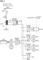
- den in der Einleitung beschriebenen Selbstlasttest samt zugehöriger Komponenten bei einer Dual-Mode-Lokomotive.
- FIG 1
- a first embodiment of the arrangement according to the invention for self-load testing in a dual-mode locomotive,
- FIG 2
- a second embodiment of the arrangement according to the invention for self-load testing in a dual-mode locomotive,
- 3
- the self-load test described in the introduction and associated components for a diesel-electric locomotive, and
- FIG 4
- the self-load test described in the introduction and associated components for a dual-mode locomotive.
Nachfolgend wird der elektrische Leistungsfluss beim Fahrbetrieb der Dual-Mode-Lokomotive LOK1 geschildert.The electrical power flow during operation of the dual-mode locomotive LOK1 is described below.
Ein erstes Antriebssystem ist über einen Dieselmotor DM realisiert. Der Dieselmotor DM wird als Verbrennungsmotor betrieben und ist über eine Kupplung mit einem Generator GEN mechanisch verbunden. Der Generator GEN wird über den Dieselmotor DM mechanisch angetrieben, wobei zur Bildung von elektrischer Leistung der Generator GEN mit einem Erregergerät ERG gekoppelt ist.A first drive system is realized via a diesel engine DM. The diesel engine DM is operated as an internal combustion engine and is mechanically connected to a generator GEN via a clutch. The generator GEN is driven mechanically via the diesel engine DM, with the generator GEN being coupled to an exciter ERG in order to generate electrical power.
Vom Generator GEN gelieferte elektrische Leistung gelangt zu einem Wechselspannungs-Gleichspannungs-Wandler WSGSW1, der aus der zugeführten Wechselspannung eine Gleichspannung bildet. Zur Reduzierung der Spannungswelligkeit im Spannungszwischenkreis ist am Wechselspannungs-Gleichspannungs-Wandler WSGSW1 ausgangsseitig ein Kondensator C parallelgeschaltet bzw. vorgesehen.Electrical power supplied by the generator GEN reaches an AC/DC converter WSGSW1, which forms a DC voltage from the AC voltage supplied. To reduce the voltage ripple in the intermediate voltage circuit, the AC/DC converter is WSGSW1 a capacitor C connected in parallel or provided on the output side.
Der Wechselspannungs-Gleichspannungs-Wandler WSGSW1 ist ausgangsseitig mit Eingängen von drei parallelgeschalteten Gleichspannungs-Wechselspannungs-Wandlern GSWSW1 bis GSWSW3 verbunden, so dass die vom Wechselspannungs-Gleichspannungs-Wandler WSGSW1 gebildete Gleichspannung an allen Eingängen der drei Gleichspannungs-Wechselspannungs-Wandlern GSWSW1 bis GSWSW3 anliegt.The AC voltage-DC voltage converter WSGSW1 is connected on the output side to inputs of three parallel-connected DC voltage-AC voltage converters GSWSW1 to GSWSW3, so that the DC voltage formed by the AC voltage-DC voltage converter WSGSW1 is present at all inputs of the three DC voltage-AC voltage converters GSWSW1 to GSWSW3 .
Durch die Ausgänge des Wechselspannungs-Gleichspannungs-Wandler WSGSW1 sowie durch die Eingänge der Gleichspannungs-Wechselspannungs-Wandler GSWSW1 bis GSWSW3 wird zusammen mit dem Kondensator C ein sogenannter Gleichspannungszwischenkreis gebildet.The outputs of the AC voltage-DC voltage converter WSGSW1 and the inputs of the DC voltage-AC voltage converters GSWSW1 to GSWSW3, together with the capacitor C, form what is known as a DC voltage intermediate circuit.
Die drei Gleichspannungs-Wechselspannungs-Wandler GSWSW1 bis GSWSW3 bilden aus der zugeführten Gleichspannung jeweilige Wechselspannungen zur weiteren Verwendung.The three DC-AC voltage converters GSWSW1 to GSWSW3 form respective AC voltages from the supplied DC voltage for further use.
Ein erster Gleichspannungs-Wechselspannungs-Wandler GSWSW1 bildet Wechselspannung für einen ersten Antriebsmotor MOT1 und für einen zweiten Antriebsmotor MOT2 des Schienenfahrzeugs bzw. der Lokomotive.A first DC/AC converter GSWSW1 forms AC voltage for a first drive motor MOT1 and for a second drive motor MOT2 of the rail vehicle or locomotive.
Ein zweiter Gleichspannungs-Wechselspannungs-Wandler GSWSW2 bildet Wechselspannung für einen dritten Antriebsmotor MOT3 und für einen vierten Antriebsmotor MOT4 des Schienenfahrzeugs bzw. der Lokomotive.A second DC/AC converter GSWSW2 forms AC voltage for a third drive motor MOT3 and for a fourth drive motor MOT4 of the rail vehicle or locomotive.
Ein dritter Gleichspannungs-Wechselspannungs-Wandler GSWSW3 bildet Wechselspannung für die Hilfsantriebe (z.B. Kompressor, Lüftung, etc.) bzw. für weitere als AUX bezeichnete Verwendungen beim Schienenfahrzeug bzw. bei der Lokomotive.A third DC-AC converter GSWSW3 forms AC voltage for the auxiliary drives (e.g. compressor, ventilation, etc.) or for other uses designated as AUX in rail vehicles or locomotives.
Der Wechselspannungs-Gleichspannungs-Wandler WSGSW1 ist ausgangsseitig darüber hinaus auch mit Eingängen eines Gleichspannungs-Gleichspannungs-Wandlers GSGSW verbunden, der ebenfalls parallel zu den drei Gleichspannungs-Wechselspannungs-Wandlern GSWSW1 bis GSWSW3 geschaltet ist.The AC voltage-DC voltage converter WSGSW1 is also connected on the output side to inputs of a DC voltage-DC voltage converter GSGSW, which is also connected in parallel with the three DC voltage-AC voltage converters GSWSW1 to GSWSW3.
Damit liegt die vom Wechselspannungs-Gleichspannungs-Wandler WSGSW1 gebildete Gleichspannung an den Eingängen des Gleichspannungs-Gleichspannungs-Wandlers GSGSW an.The DC voltage formed by the AC voltage/DC voltage converter WSGSW1 is therefore present at the inputs of the DC voltage/DC voltage converter GSGSW.
Die Eingänge des Gleichspannungs-Gleichspannungs-Wandlers GSGSW sind ebenfalls Bestandteil des Gleichspannungszwischenkreises.The inputs of the DC voltage-DC voltage converter GSGSW are also part of the DC voltage intermediate circuit.
Am Gleichspannungs-Gleichspannungs-Wandler GSGSW ist ausgangsseitig ein Bremswiderstand RBR angeschlossen.A braking resistor RBR is connected to the output side of the DC voltage-DC voltage converter GSGSW.
Beim Bremsen der Antriebsmotoren MOT1 bis MOT4 wird nicht benötigte Leistung bzw. Energie vom Gleichspannungszwischenkreis über den Gleichspannungs-Gleichspannungs-Wandler GSGSW dem Bremswiderstand RBR zugeführt, der diese in Wärme umwandelt.When braking the drive motors MOT1 to MOT4, power or energy that is not required is fed from the DC link via the DC/DC converter GSGSW to the braking resistor RBR, which converts it into heat.
Als Alternative zum Antriebstrang über den Dieselmotor DM ist hier ein weiterer Antriebsstrang vorgesehen, der auf dem elektrischen Betrieb mit einem Stromabnehmer bzw. Pantographen PANT basiert.As an alternative to the drive train via the DM diesel engine, another drive train is provided here, which is based on electrical operation with a pantograph or pantograph PANT.
Der Stromabnehmer PANT entnimmt einer Oberleitung bzw. Hochspannungsleitung HSPL elektrische Leistung bzw. Energie und führt diese über einen Hauptschalter HS einem Transformator TR zu.The pantograph PANT draws electrical power or energy from an overhead line or high-voltage line HSPL feeds them to a transformer TR via a main switch HS.
Der Transformator TR bildet aus einer ihm zugeführten Eingangswechselspannung eine vorbestimmte Ausgangswechselspannung, die an Eingänge eines weiteren Wechselspannungs-Gleichspannungs-Wandlers WSGSW2 gelangt.From an input AC voltage supplied to it, the transformer TR forms a predetermined output AC voltage, which reaches the inputs of a further AC/DC converter WSGSW2.
Der Wechselspannungs-Gleichspannungs-Wandler WSGSW2 bildet aus der ihm zugeführten Wechselspannung eine Gleichspannung für den Gleichspannungszwischenkreis.The AC voltage-DC voltage converter WSGSW2 forms a DC voltage for the DC voltage intermediate circuit from the AC voltage fed to it.
Diese gelangt an die Eingänge der drei Gleichspannungs-Wechselspannungs-Wandler GSWSW1 bis GSWSW3 sowie an die Eingänge des Gleichspannungs-Gleichspannungs-Wandlers GSGSW und von dort, wie vorstehend beschrieben, zur jeweiligen weiteren Verwendung.This reaches the inputs of the three DC/AC converters GSWSW1 to GSWSW3 and the inputs of the DC/DC converter GSGSW and from there, as described above, for further use.
Nachfolgend wird der elektrische Leistungsfluss beim Selbsttest des Dieselmotors DM der Dual-Mode-Lokomotive LOK1 geschildert.The electrical power flow during the self-test of the diesel engine DM of the dual-mode locomotive LOK1 is described below.
Die beim Selbsttest des Dieselmotors DM gebildete elektrische Leistung gelangt wie vorstehend beschrieben in den Gleichspannungszwischenkreis.As described above, the electrical power generated during the self-test of the diesel engine DM reaches the intermediate DC voltage circuit.
Seitens der Motoren MOT1 bis MOT4 wird beim Selbsttest keine Leistung benötigt, so dass die Leistung wie nachfolgend beschrieben aufgeteilt wird.No power is required on the part of the motors MOT1 to MOT4 during the self-test, so the power is divided as described below.
Ein erster Anteil E1 der Leistung gelangt über den Gleichspannungs-Gleichspannungs-Wandler GSGSW an den Bremswiderstand RBR, der im Schienenfahrzeug bzw. in der Lokomotive angeordnet ist. Der Bremswiderstand RBR wandelt die ihm zugeführte elektrische Teilleistung E1 in Wärme um.A first portion E1 of the power reaches the braking resistor RBR, which is arranged in the rail vehicle or in the locomotive, via the DC voltage-DC voltage converter GSGSW is. The braking resistor RBR converts the partial electrical power E1 supplied to it into heat.
Ein zweiter Anteil E2 der Leistung gelangt aus dem Gleichspannungszwischenkreis über eine Serienschaltung, die den Wandler WSGSW2, den Transformator TR, den Hauptschalter HS und den Pantografen PANT umfasst, zur Hochspannungsleitung HSPL.A second portion E2 of the power reaches the high-voltage line HSPL from the DC link via a series circuit that includes the converter WSGSW2, the transformer TR, the main switch HS and the pantograph PANT.
Aufgrund der Aufteilung der Leistung kann vorteilhaft auf einen Schienenfahrzeug-externen Lastwiderstand verzichtet werden.Due to the distribution of the power, a load resistor external to the rail vehicle can advantageously be dispensed with.
Mit Bezug auf
Abweichend zu
Vorteilhaft kann hier auf die Mitwirkung des Bremswiderstands RBR gänzlich verzichtet werden. Der Bremswiderstand RBR ist somit stromlos.Advantageously, the participation of the braking resistor RBR can be completely dispensed with here. The braking resistor RBR is therefore currentless.
Claims (9)
- Arrangement for carrying out a self-load test,
having a rail vehicle (LOK1, LOK2) that has a dual-mode drive system (GEN, HSPL),- in which a first drive system (DM) of the rail vehicle (LOK1, LOK2) comprises a diesel engine (DM) that is coupled to an electric generator (GEN) in order to generate electrical power,- in which the output side of the generator (GEN) is connected to a DC link via a first converter (WSGSW1), which is connected downstream of said generator and is connected as an AC/DC converter, so that the power delivered by the generator (GEN) can be transmitted as required via the first converter (WSGSW1) into the DC link,- in which a second drive system (HSPL) of the rail vehicle has an electrical line system (HSPL) that is connected to the DC link via a second converter (WSGSW2), which is connected downstream of said electrical line system, so that power from the line system (HSPL) can be transmitted as required into the DC link,- in which the DC link is connected via a third converter (GSGSW) to a braking resistor (RBR) that is arranged inside the rail vehicle (LOK1, LOK2),- in which the third converter (GSGSW) is connected as a DC/DC converter in order to transmit power that is no longer required from the DC link to the braking resistor (RBR) during braking,- in which the braking resistor (RBR) is dimensioned in such a way that it converts the power that is fed to it into heat,- in which, during a self-load test of the diesel engine (DM), the diesel engine has a load applied to it, which in the maximum case corresponds to the nominal load of the diesel engine, for the purpose of suitability testing,- in which, during the self-load test, the generator (GEN), the first converter (WSGSW1), the DC link and the third converter (GSGSW) are connected in such a way that a first portion (E1) of the power that is generated by the diesel engine (DM) and passes via the first converter (WSGSW1) into the DC link is fed from there via the third converter (GSGSW), which is connected as a DC/DC converter, to the braking resistor (RBR), and- in which, during the self-load test, the generator (GEN), the first converter (WSGSW1), the DC link, the second converter (WSGSW2) and the line system (HSPL) are connected in such a way- that a second portion (E2) of the power that is generated by the diesel engine (DM) and passes via the first converter (WSGSW1) into the DC link is fed from there via the second converter (WSGSW2) to the line system (HSPL), and- that the power fed to the second converter (WSGSW2) is fed into the line system (HSPL). - Arrangement according to Claim 1, in which the line system (HSPL) is designed as an overhead line system or as a line system that is close to the rails.
- Arrangement according to one of the preceding claims, in which the line system is designed as a DC-based line system or as an AC-based line system.
- Arrangement according to Claim 3,- in which the AC-based line system (HSPL) is connected to the second converter (WSGSW2) via a transformer (TR),- in which the second converter (WSGSW2) is connected as an AC/DC converter in order to transmit power from the line system (HSPL) to the DC link,- in which the second converter (WSGSW2) is connected as a DC/AC converter in order to transmit power from the DC link to the line system (HSPL) during the self-load test.
- Arrangement according to one of the preceding claims,- in which at least one electric motor (MOT1, ...), which is coupled to a wheel of the rail vehicle (LOK1, LOK2) as drive motor of the rail vehicle (LOK1, LOK2), is connected to the DC link via a further converter (GSWSW1, GSWSW2), and- in which said converter (GSWSW1, GSWSW2) is designed as a DC/AC converter and is connected in such a way that power is transmitted from the DC link to the drive motor (MOT1, ...).
- Method for carrying out a self-load test in a rail vehicle (LOK1, LOK2) that has a dual-mode drive system (GEN, HSPL),- in which, in a first drive system (DM) of the rail vehicle (LOK1, LOK2), a diesel engine (DM) drives an electric generator (GEN) through coupling in order to generate electrical power,- in which the electrical power delivered by the generator (GEN) passes as required via a first converter (WSGSW1), which is operated as an AC/DC converter, to a DC link,- in which a second drive system (HSPL) of the rail vehicle draws power from an electrical line system (HSPL) as required and passes it to the DC link via a second converter (WSGSW2),- in which a third converter (GSGSW), the input side of which is connected to the DC link and the output side of which is connected to a braking resistor (RBR) arranged inside the rail vehicle (LOK1, LOK2), is controlled as a DC/DC converter in such a way that, during braking, power that is no longer required is fed from the DC link to the braking resistor (RBR),- in which the braking resistor (RBR) converts the power that is fed to it into heat,- in which, during a self-load test of the diesel engine (DM), the diesel engine has a load applied to it, which in the maximum case corresponds to the nominal load of the diesel engine, for the purpose of suitability testing,- in which, during the self-load test, the third converter (GSGSW) is controlled as a DC/DC converter in such a way that a first portion (E1) of the power that is generated by the diesel engine (DM) and passes via the first converter (WSGSW1) into the DC link is fed from there via the third converter (GSGSW) to the braking resistor (RBR),- in which, during the self-load test, the second converter (WSGSW2) is controlled in such a way that a second portion (E2) of the power that is generated by the diesel engine (DM) and passes via the first converter (WSGSW1) into the DC link is fed from there via the second converter (WSGSW2) to the line system (HSPL), and- in which the power fed to the second converter (WSGSW2) is fed into the line system (HSPL).
- Method according to Claim 6,- in which an overhead line system or a line system that is close to the rails is used as line system (HSPL), and/or- in which a DC-based line system or an AC-based line system is used as line system.
- Method according to Claim 7,- in which the AC-based line system (HSPL) is connected to the second converter (WSGSW2) via a transformer (TR),- in which the second converter (WSGSW2) is used as an AC/DC converter in order to transmit power from the line system (HSPL) to the DC link,- in which the second converter (WSGSW2) is used as a DC/AC converter in order to transmit power from the DC link to the line system (HSPL) during the self-load test.
- Method according to one of Claims 6 to 8,- in which at least one electric motor (MOT1, ...) is used as drive motor of the rail vehicle (LOK1, LOK2), wherein the motor is coupled to a wheel of the rail vehicle (LOK1, LOK2),- in which the electric motor is connected to the DC link via a further converter (GSWSW1, GSWSW2), and- in which said converter (GSWSW1, GSWSW2) is operated as a DC/AC converter in order to transmit power from the DC link to the drive motor (MOT1, ...).
Applications Claiming Priority (2)
| Application Number | Priority Date | Filing Date | Title |
|---|---|---|---|
| DE102020205179 | 2020-04-23 | ||
| PCT/EP2021/055524 WO2021213724A1 (en) | 2020-04-23 | 2021-03-04 | Arrangement and method for carrying out a self-load test on a rail vehicle |
Publications (2)
| Publication Number | Publication Date |
|---|---|
| EP4100275A1 EP4100275A1 (en) | 2022-12-14 |
| EP4100275B1 true EP4100275B1 (en) | 2023-07-12 |
Family
ID=75108304
Family Applications (1)
| Application Number | Title | Priority Date | Filing Date |
|---|---|---|---|
| EP21712965.9A Active EP4100275B1 (en) | 2020-04-23 | 2021-03-04 | Arrangement and method for carrying out a self-load test on a rail vehicle |
Country Status (6)
| Country | Link |
|---|---|
| US (1) | US20230184632A1 (en) |
| EP (1) | EP4100275B1 (en) |
| CN (1) | CN115427252A (en) |
| ES (1) | ES2952670T3 (en) |
| PL (1) | PL4100275T3 (en) |
| WO (1) | WO2021213724A1 (en) |
Citations (1)
| Publication number | Priority date | Publication date | Assignee | Title |
|---|---|---|---|---|
| EP1186497B1 (en) * | 2000-09-12 | 2006-03-29 | ALSTOM LHB GmbH | Railway vehicle with power supply system |
Family Cites Families (11)
| Publication number | Priority date | Publication date | Assignee | Title |
|---|---|---|---|---|
| US20060005739A1 (en) * | 2001-03-27 | 2006-01-12 | Kumar Ajith K | Railroad system comprising railroad vehicle with energy regeneration |
| US7344202B2 (en) * | 2005-05-11 | 2008-03-18 | General Electric Company | System and method for dealing with ground fault conditions that can arise in an electrical propulsion system |
| DE102006010536B4 (en) * | 2006-03-07 | 2008-06-12 | Siemens Ag | Diesel-electric drive system with a permanently excited synchronous generator |
| DE102007003172B4 (en) * | 2006-08-08 | 2011-06-01 | Siemens Ag | Diesel electric drive system |
| WO2008144901A1 (en) * | 2007-05-25 | 2008-12-04 | Railpower Technologies Corp. | Power architecture and braking circuits for dc motor-propelled vehicle |
| US9415781B2 (en) * | 2008-12-23 | 2016-08-16 | Progress Rail Services Corporation | Dual engine locomotive |
| US9784194B2 (en) * | 2014-06-30 | 2017-10-10 | General Electric Company | Systems for a multi-fuel capable engine |
| WO2013114546A1 (en) * | 2012-01-30 | 2013-08-08 | 三菱電機株式会社 | Propulsion control device of electric vehicle and control method thereof |
| US9008879B2 (en) * | 2012-07-05 | 2015-04-14 | General Electric Company | System and method for operating a hybrid vehicle system |
| JP6974913B2 (en) * | 2016-11-30 | 2021-12-01 | 株式会社辰巳菱機 | Load test system |
| CN110406549B (en) * | 2019-09-04 | 2024-03-01 | 宝鸡中车时代工程机械有限公司 | Hybrid power rail car drawn by diesel engine and power storage battery |
-
2021
- 2021-03-04 WO PCT/EP2021/055524 patent/WO2021213724A1/en active Search and Examination
- 2021-03-04 ES ES21712965T patent/ES2952670T3/en active Active
- 2021-03-04 EP EP21712965.9A patent/EP4100275B1/en active Active
- 2021-03-04 US US17/920,873 patent/US20230184632A1/en active Pending
- 2021-03-04 CN CN202180029754.8A patent/CN115427252A/en active Pending
- 2021-03-04 PL PL21712965.9T patent/PL4100275T3/en unknown
Patent Citations (1)
| Publication number | Priority date | Publication date | Assignee | Title |
|---|---|---|---|---|
| EP1186497B1 (en) * | 2000-09-12 | 2006-03-29 | ALSTOM LHB GmbH | Railway vehicle with power supply system |
Also Published As
| Publication number | Publication date |
|---|---|
| CN115427252A (en) | 2022-12-02 |
| PL4100275T3 (en) | 2023-11-27 |
| EP4100275A1 (en) | 2022-12-14 |
| WO2021213724A1 (en) | 2021-10-28 |
| US20230184632A1 (en) | 2023-06-15 |
| ES2952670T3 (en) | 2023-11-03 |
Similar Documents
| Publication | Publication Date | Title |
|---|---|---|
| EP2229291B1 (en) | Arrangement for supplying devices of a locomotive with electric energy and method for operating said arrangement | |
| DE112013006718B4 (en) | Drive control device for rail vehicles | |
| DE102010028972B4 (en) | Motor drive system for a hybrid vehicle and method for controlling the same | |
| EP2277259B1 (en) | Diesel-electric drive system | |
| EP2810351A1 (en) | Charging device | |
| EP2822802A2 (en) | Device for an electrically driven rail vehicle | |
| WO2013159887A1 (en) | Motor vehicle having a high-voltage power supply system | |
| DE102017206497A1 (en) | Charging device and method for charging an electrical energy storage device of a vehicle, and motor vehicle | |
| DE102012208241A1 (en) | Rail vehicle circuitry | |
| DE102016204701B4 (en) | vehicle drive system | |
| EP4100275B1 (en) | Arrangement and method for carrying out a self-load test on a rail vehicle | |
| DE9403447U1 (en) | Power supply device for passenger coaches | |
| DE19908495B4 (en) | From an AC contact wire supplied, transformerless feed circuit for an alternator of a railway vehicle | |
| AT521412A1 (en) | track vehicle | |
| EP3867620B1 (en) | Roller test stand and method for operating a roller test stand | |
| EP2040954B1 (en) | System and method for supplying customers in a railcar | |
| EP3849869B1 (en) | Arrangement for driving a locomotive having various energy-provision systems | |
| EP3184349A1 (en) | Energy supply system for vehicle and vehicle with electric traction system | |
| EP3736168A1 (en) | Drive system for a diesel-electric vehicle | |
| EP2670042B1 (en) | Power converter with redundant link circuit voltage measuring circuit, and method for operating a power converter | |
| AT523185B1 (en) | Test bench for driving a vehicle | |
| DE102022201132A1 (en) | Charger for an electrified vehicle and method of operating a charger for an electrified vehicle | |
| WO2022037800A1 (en) | Dual mode locomotive | |
| DE102016104541B4 (en) | Charging system for electric and hybrid vehicles and a method for charging with a charging system | |
| WO2023036510A1 (en) | Device and method for heating a traction battery |
Legal Events
| Date | Code | Title | Description |
|---|---|---|---|
| STAA | Information on the status of an ep patent application or granted ep patent |
Free format text: STATUS: UNKNOWN |
|
| STAA | Information on the status of an ep patent application or granted ep patent |
Free format text: STATUS: THE INTERNATIONAL PUBLICATION HAS BEEN MADE |
|
| PUAI | Public reference made under article 153(3) epc to a published international application that has entered the european phase |
Free format text: ORIGINAL CODE: 0009012 |
|
| STAA | Information on the status of an ep patent application or granted ep patent |
Free format text: STATUS: REQUEST FOR EXAMINATION WAS MADE |
|
| 17P | Request for examination filed |
Effective date: 20220909 |
|
| AK | Designated contracting states |
Kind code of ref document: A1 Designated state(s): AL AT BE BG CH CY CZ DE DK EE ES FI FR GB GR HR HU IE IS IT LI LT LU LV MC MK MT NL NO PL PT RO RS SE SI SK SM TR |
|
| GRAP | Despatch of communication of intention to grant a patent |
Free format text: ORIGINAL CODE: EPIDOSNIGR1 |
|
| STAA | Information on the status of an ep patent application or granted ep patent |
Free format text: STATUS: GRANT OF PATENT IS INTENDED |
|
| DAV | Request for validation of the european patent (deleted) | ||
| DAX | Request for extension of the european patent (deleted) | ||
| INTG | Intention to grant announced |
Effective date: 20230315 |
|
| GRAS | Grant fee paid |
Free format text: ORIGINAL CODE: EPIDOSNIGR3 |
|
| GRAA | (expected) grant |
Free format text: ORIGINAL CODE: 0009210 |
|
| STAA | Information on the status of an ep patent application or granted ep patent |
Free format text: STATUS: THE PATENT HAS BEEN GRANTED |
|
| AK | Designated contracting states |
Kind code of ref document: B1 Designated state(s): AL AT BE BG CH CY CZ DE DK EE ES FI FR GB GR HR HU IE IS IT LI LT LU LV MC MK MT NL NO PL PT RO RS SE SI SK SM TR |
|
| REG | Reference to a national code |
Ref country code: CH Ref legal event code: EP |
|
| REG | Reference to a national code |
Ref country code: DE Ref legal event code: R096 Ref document number: 502021001004 Country of ref document: DE |
|
| REG | Reference to a national code |
Ref country code: IE Ref legal event code: FG4D Free format text: LANGUAGE OF EP DOCUMENT: GERMAN |
|
| REG | Reference to a national code |
Ref country code: ES Ref legal event code: FG2A Ref document number: 2952670 Country of ref document: ES Kind code of ref document: T3 Effective date: 20231103 |
|
| REG | Reference to a national code |
Ref country code: LT Ref legal event code: MG9D |
|
| REG | Reference to a national code |
Ref country code: NL Ref legal event code: MP Effective date: 20230712 |
|
| PG25 | Lapsed in a contracting state [announced via postgrant information from national office to epo] |
Ref country code: NL Free format text: LAPSE BECAUSE OF FAILURE TO SUBMIT A TRANSLATION OF THE DESCRIPTION OR TO PAY THE FEE WITHIN THE PRESCRIBED TIME-LIMIT Effective date: 20230712 |
|
| PG25 | Lapsed in a contracting state [announced via postgrant information from national office to epo] |
Ref country code: GR Free format text: LAPSE BECAUSE OF FAILURE TO SUBMIT A TRANSLATION OF THE DESCRIPTION OR TO PAY THE FEE WITHIN THE PRESCRIBED TIME-LIMIT Effective date: 20231013 |
|
| PG25 | Lapsed in a contracting state [announced via postgrant information from national office to epo] |
Ref country code: IS Free format text: LAPSE BECAUSE OF FAILURE TO SUBMIT A TRANSLATION OF THE DESCRIPTION OR TO PAY THE FEE WITHIN THE PRESCRIBED TIME-LIMIT Effective date: 20231112 |
|
| PG25 | Lapsed in a contracting state [announced via postgrant information from national office to epo] |
Ref country code: SE Free format text: LAPSE BECAUSE OF FAILURE TO SUBMIT A TRANSLATION OF THE DESCRIPTION OR TO PAY THE FEE WITHIN THE PRESCRIBED TIME-LIMIT Effective date: 20230712 Ref country code: RS Free format text: LAPSE BECAUSE OF FAILURE TO SUBMIT A TRANSLATION OF THE DESCRIPTION OR TO PAY THE FEE WITHIN THE PRESCRIBED TIME-LIMIT Effective date: 20230712 Ref country code: PT Free format text: LAPSE BECAUSE OF FAILURE TO SUBMIT A TRANSLATION OF THE DESCRIPTION OR TO PAY THE FEE WITHIN THE PRESCRIBED TIME-LIMIT Effective date: 20231113 Ref country code: NO Free format text: LAPSE BECAUSE OF FAILURE TO SUBMIT A TRANSLATION OF THE DESCRIPTION OR TO PAY THE FEE WITHIN THE PRESCRIBED TIME-LIMIT Effective date: 20231012 Ref country code: LV Free format text: LAPSE BECAUSE OF FAILURE TO SUBMIT A TRANSLATION OF THE DESCRIPTION OR TO PAY THE FEE WITHIN THE PRESCRIBED TIME-LIMIT Effective date: 20230712 Ref country code: LT Free format text: LAPSE BECAUSE OF FAILURE TO SUBMIT A TRANSLATION OF THE DESCRIPTION OR TO PAY THE FEE WITHIN THE PRESCRIBED TIME-LIMIT Effective date: 20230712 Ref country code: IS Free format text: LAPSE BECAUSE OF FAILURE TO SUBMIT A TRANSLATION OF THE DESCRIPTION OR TO PAY THE FEE WITHIN THE PRESCRIBED TIME-LIMIT Effective date: 20231112 Ref country code: HR Free format text: LAPSE BECAUSE OF FAILURE TO SUBMIT A TRANSLATION OF THE DESCRIPTION OR TO PAY THE FEE WITHIN THE PRESCRIBED TIME-LIMIT Effective date: 20230712 Ref country code: GR Free format text: LAPSE BECAUSE OF FAILURE TO SUBMIT A TRANSLATION OF THE DESCRIPTION OR TO PAY THE FEE WITHIN THE PRESCRIBED TIME-LIMIT Effective date: 20231013 Ref country code: FI Free format text: LAPSE BECAUSE OF FAILURE TO SUBMIT A TRANSLATION OF THE DESCRIPTION OR TO PAY THE FEE WITHIN THE PRESCRIBED TIME-LIMIT Effective date: 20230712 |
|
| REG | Reference to a national code |
Ref country code: DE Ref legal event code: R097 Ref document number: 502021001004 Country of ref document: DE |
|
| PG25 | Lapsed in a contracting state [announced via postgrant information from national office to epo] |
Ref country code: SM Free format text: LAPSE BECAUSE OF FAILURE TO SUBMIT A TRANSLATION OF THE DESCRIPTION OR TO PAY THE FEE WITHIN THE PRESCRIBED TIME-LIMIT Effective date: 20230712 Ref country code: RO Free format text: LAPSE BECAUSE OF FAILURE TO SUBMIT A TRANSLATION OF THE DESCRIPTION OR TO PAY THE FEE WITHIN THE PRESCRIBED TIME-LIMIT Effective date: 20230712 Ref country code: EE Free format text: LAPSE BECAUSE OF FAILURE TO SUBMIT A TRANSLATION OF THE DESCRIPTION OR TO PAY THE FEE WITHIN THE PRESCRIBED TIME-LIMIT Effective date: 20230712 Ref country code: DK Free format text: LAPSE BECAUSE OF FAILURE TO SUBMIT A TRANSLATION OF THE DESCRIPTION OR TO PAY THE FEE WITHIN THE PRESCRIBED TIME-LIMIT Effective date: 20230712 Ref country code: SK Free format text: LAPSE BECAUSE OF FAILURE TO SUBMIT A TRANSLATION OF THE DESCRIPTION OR TO PAY THE FEE WITHIN THE PRESCRIBED TIME-LIMIT Effective date: 20230712 |
|
| PGFP | Annual fee paid to national office [announced via postgrant information from national office to epo] |
Ref country code: CZ Payment date: 20240227 Year of fee payment: 4 |
|
| PLBE | No opposition filed within time limit |
Free format text: ORIGINAL CODE: 0009261 |
|
| STAA | Information on the status of an ep patent application or granted ep patent |
Free format text: STATUS: NO OPPOSITION FILED WITHIN TIME LIMIT |
|
| PGFP | Annual fee paid to national office [announced via postgrant information from national office to epo] |
Ref country code: PL Payment date: 20240223 Year of fee payment: 4 Ref country code: FR Payment date: 20240319 Year of fee payment: 4 |
|
| 26N | No opposition filed |
Effective date: 20240415 |
|
| PGFP | Annual fee paid to national office [announced via postgrant information from national office to epo] |
Ref country code: DE Payment date: 20240517 Year of fee payment: 4 |
|
| PGFP | Annual fee paid to national office [announced via postgrant information from national office to epo] |
Ref country code: CH Payment date: 20240604 Year of fee payment: 4 |
|
| PGFP | Annual fee paid to national office [announced via postgrant information from national office to epo] |
Ref country code: ES Payment date: 20240627 Year of fee payment: 4 |
|
| PG25 | Lapsed in a contracting state [announced via postgrant information from national office to epo] |
Ref country code: SI Free format text: LAPSE BECAUSE OF FAILURE TO SUBMIT A TRANSLATION OF THE DESCRIPTION OR TO PAY THE FEE WITHIN THE PRESCRIBED TIME-LIMIT Effective date: 20230712 |
|
| PGFP | Annual fee paid to national office [announced via postgrant information from national office to epo] |
Ref country code: IT Payment date: 20240401 Year of fee payment: 4 |