EP4100186B1 - Outil de laminage et procédé de laminage d'un profilé - Google Patents
Outil de laminage et procédé de laminage d'un profilé Download PDFInfo
- Publication number
- EP4100186B1 EP4100186B1 EP21705114.3A EP21705114A EP4100186B1 EP 4100186 B1 EP4100186 B1 EP 4100186B1 EP 21705114 A EP21705114 A EP 21705114A EP 4100186 B1 EP4100186 B1 EP 4100186B1
- Authority
- EP
- European Patent Office
- Prior art keywords
- rolling
- disc
- workpiece
- profile
- tool
- Prior art date
- Legal status (The legal status is an assumption and is not a legal conclusion. Google has not performed a legal analysis and makes no representation as to the accuracy of the status listed.)
- Active
Links
Images


Classifications
-
- B—PERFORMING OPERATIONS; TRANSPORTING
- B21—MECHANICAL METAL-WORKING WITHOUT ESSENTIALLY REMOVING MATERIAL; PUNCHING METAL
- B21H—MAKING PARTICULAR METAL OBJECTS BY ROLLING, e.g. SCREWS, WHEELS, RINGS, BARRELS, BALLS
- B21H5/00—Making gear wheels, racks, spline shafts or worms
- B21H5/02—Making gear wheels, racks, spline shafts or worms with cylindrical outline, e.g. by means of die rolls
-
- B—PERFORMING OPERATIONS; TRANSPORTING
- B21—MECHANICAL METAL-WORKING WITHOUT ESSENTIALLY REMOVING MATERIAL; PUNCHING METAL
- B21H—MAKING PARTICULAR METAL OBJECTS BY ROLLING, e.g. SCREWS, WHEELS, RINGS, BARRELS, BALLS
- B21H5/00—Making gear wheels, racks, spline shafts or worms
-
- B—PERFORMING OPERATIONS; TRANSPORTING
- B21—MECHANICAL METAL-WORKING WITHOUT ESSENTIALLY REMOVING MATERIAL; PUNCHING METAL
- B21H—MAKING PARTICULAR METAL OBJECTS BY ROLLING, e.g. SCREWS, WHEELS, RINGS, BARRELS, BALLS
- B21H3/00—Making helical bodies or bodies having parts of helical shape
- B21H3/02—Making helical bodies or bodies having parts of helical shape external screw-threads ; Making dies for thread rolling
- B21H3/06—Making by means of profiled members other than rolls, e.g. reciprocating flat dies or jaws, moved longitudinally or curvilinearly with respect to each other
Definitions
- the invention relates to a rolling tool and a method for rolling a profile, in particular a spline on a workpiece.
- a rolling machine with incremental round rolling tools and a method for cold rolling longitudinal gears and profiles on a workpiece are known.
- Two rolling spindles are mounted parallel to each other on a rolling carriage so that they can be freely positioned in the feed direction toward the workpiece and, at the same time, in the axial direction relative to the workpiece.
- the rolling spindles are driven synchronously by a CNC control of the profile rolling machine and are advanced in stages to apply the gearing to the workpiece in sections.
- Push-through rolling processes are mostly used in the production of long profiles and/or on hollow shafts. to keep the pressure on the workpiece low. Excessive pressure can lead to cracking and distortion of the workpiece, which is undesirable.
- round tools are not limited to the DE 10 2007 039 959 A1 described arrangement and operating conditions.
- three or more round rolling tools can be arranged around the workpiece to apply a profile to a workpiece, see for example DE 803 232 A1 .
- the WO2019020619 A1 discloses a rolling tool for rolling a profile in a push-through rolling process with a rolling disk which comprises an inlet region for rolling the workpiece, wherein the rolling disk has a chamfer forming the inlet region.
- the invention is based on the object of creating a rolling tool for rolling a profile, in particular a spline on a workpiece, and a corresponding method therefor, which overcome the disadvantages of the prior art.
- the object is achieved by a rolling tool and a method for producing, in particular rolling or rolling, a profile, in particular a spline on a workpiece, according to the features of the independent patent claims.
- Advantageous embodiments are characterized by the features of the subclaims.
- a rolling tool for rolling a profile in particular a spline on a workpiece, comprises a rolling disk assembly having at least one main disk and an interchangeable disk releasably and non-rotatably attached thereto.
- the interchangeable disk is positioned upstream of the main disk with respect to a working direction.
- the components referred to as discs in the present disclosure can be components of a rolling beam as well as of a round rolling tool.
- a working direction is identified with the direction of workpiece feed.
- the working direction can, but does not necessarily have to, coincide with a main or rotational axis of the disc stack.
- the working direction runs perpendicular to the movement of the rolling beam during the rolling process.
- the device is configured to perform a push-through rolling process.
- the interchangeable disc includes an inlet area for rolling the workpiece.
- the interchangeable disc first encounters the workpiece and is primarily subjected to stress by it, meaning that most of the forming work is performed by the interchangeable disc. Since this disc is detachably attached to the main disc, it can be easily replaced when it wears out. This results in significant material savings, as the main disc and any other existing discs can ideally be reused.
- the interchangeable disc is designed to have a profile depression or chamfer on the front side in the working direction, which forms the lead-in area.
- the chamfer area is designed so that in this area the profile rises from the front side towards the calibration.
- the teeth become increasingly deeper until they approach the final tooth shape.
- the profile depression has a uniform profile depth along the working direction, but is machined at an angle to the working direction, so that the workpiece only meshes gradually with the workpiece along the working direction.
- the invention can be used for rolling both short and long workpieces, in particular for example for the production of toothed shafts, gears, rotor shafts etc.
- the invention is particularly suitable for forming external gear teeth on gear wheels or gear shafts.
- Helical or spiral gear teeth and the like can also be produced with the tool according to the invention.
- the workpieces can also be solid or hollow. Due to the relatively low pressure on the workpiece, this application is particularly suitable for hollow workpieces and/or long profiles.
- the profile of the discs can be any desired; for example, serrations or involute teeth can be created on the workpiece.
- the interchangeable disc can be made of the same material as or a different from the main disc. Due to the fact that the interchangeable disc performs the most work on the workpiece during operation, it can be advantageous to use a higher-quality material for the interchangeable disc than for the main disc, such as carbide. This can save costs in the event of wear and tear, while also increasing service life. Alternatively, a less expensive material than the main disc can be used.
- the interchangeable disc and the main disc, or just the interchangeable disc, can also be coated to optimize material properties.
- the width of the interchangeable disc can be in the range of 2 to 50%, preferably in the range between 5 and 10%.
- a chamfer angle or profile drop angle in the entry area is preferably as small as possible, since the deformation per feed should be as small as possible.
- the angle is preferably between 5° and 35°, more preferably between 10° and 20°, in particular approximately 15°. At angles smaller than 5°, the entry area would become too large, leading to high material costs for the tool.
- the chamfer angle or profile drop angle in the entry area is often limited in size by the component geometry.
- the rolling disk package in particular the interchangeable disk and/or the main disk, can have a calibration area which is characterized by a constant profile height, in particular constant tooth height and tooth shape, along the working direction.
- the rolling disk stack in particular the main disk, has a relief zone, which is preferably characterized by a profile depression along the working direction.
- a constant profile depth with a recessed profile at an angle can preferably be provided, but alternatively, a reduction in the profile depth or a change in the profile shape can also be provided, so that the workpiece gradually meshes less with the tool during feed.
- the relief area is located downstream of the calibration area with respect to the working direction.
- a first relief area can be provided upstream of the calibration area and a second relief area downstream of the calibration area.
- the rolling disk assembly also comprises a chamfering disk characterized by a profile elevation along the working direction.
- workpieces with a length approximately equal to the length of the main disk can be provided with threading chamfers for the profile, for example, for the gearing.
- the chamfering of the gearing on the workpiece serves, for example, to improve the compatibility with the components, for example, with external splines of gear wheels or shafts that are inserted into a hub with counter-toothing.
- the chamfering disc can be detachably attached to the main disc and, in particular, positioned downstream of the main disc in relation to the working direction. A workpiece which is processed in the machine and moved past the tool therefore first comes into contact with the interchangeable disc, then with the main disc and finally with the chamfering disc.
- the main disc itself can have a chamfering area which, for example, adjoins the calibration area or the relief area, i.e. is positioned downstream of it.
- One advantage of a separate chamfering disc is that it is easier to manufacture the tool, since manufacturing the calibration, relief and chamfering areas as a single piece is complex.
- the profile of the main disc and/or the interchangeable disc can be homogeneous, i.e. of the same design. Alternatively, an incremental profile shape can also be provided within the transverse plane.
- a transverse plane is a plane which is perpendicular to the working direction.
- a rolling arrangement comprises at least one, preferably two, three, or four rolling tools as described above, which are preferably arranged in a planetary manner around a rolling region.
- the rolling arrangement also comprises at least one controller, for example a CNC controller, which is configured to position the rolling tools toward one another and to enable axial displacement of the workpiece relative to the tools, for example by advancing the workpiece against stationary rolling tools.
- the controller can axially displace the rolling tools against a stationary workpiece.
- a profile in particular a spline on a workpiece by means of a rolling tool, in which an axial feed of the workpiece to the rolling tool along a working direction takes place during a forming of the workpiece, e.g. in the case of stationary rolling tools or stationary workpiece, it is provided that the profile is formed in the inlet area, an optional calibration area and the relief area of the rolling tool.
- the method is carried out using the rolling tools described above.
- the features disclosed with reference to the rolling tool are accordingly also to be understood as disclosed with reference to the method.
- the functional width of the individual areas can be adjusted as a function of the axial feed rate.
- the width of a calibration area can be adjusted to the axial feed rate so that each area on the workpiece comes into contact with a corresponding counterpart on the calibration area at least once.
- the feed of the workpiece to the rolling tool along the working direction is preferably a feed movement with a constant or variable feed rate.
- the invention is illustrated and described below using a circular tool as an example. However, the invention is also applicable to rolling bars as rolling tools.
- Fig. 1 shows a rolling arrangement 2 of a rolling machine with two rolling tools 10 arranged parallel and at a distance from one another, in particular round rolling tools, which define a clear width between them for receiving a workpiece 4.
- the rolling machine is designed, for example, for cold rolling profiles 6 such as, as shown, longitudinal gearing of shaft-shaped workpieces 4.
- the rolling tools 10 are arranged, for example, on computer-controlled rolling carriages that can be freely positioned.
- the rolling tools 10 are driven in synchronous rotation by a control system (not shown), such as a CNC control system, and at the same time are advanced towards one another by means of the control system, so that the workpiece 4 comes into contact or engagement with the profile of the rolling tools 10.
- the control system pushes the workpiece 4 through the rolling tools 10 in a working direction 8, which here coincides, for example, with the main axes 30 of the rolling tools 10.
- the feed is created by a relative movement between the workpiece 4 and the rolling tools 10, e.g.
- the workpiece 4 by shifting the workpiece 4 relative to stationary rolling tools 10, or by shifting the rolling tools 10 relative to the stationary workpiece 4.
- the feed can be continuous or variable speed.
- the workpiece 4 After rolling, the workpiece 4 has the profile 6.
- the workpiece 4 During the process, the workpiece is mounted in a workpiece holder 9, for example between centering centers.
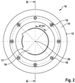
- Fig. 2 shows a rolling tool 10 according to an embodiment of the invention in a front view.
- the perspective shows, in the words of the present disclosure, a transverse plane of the rolling tool 10, since the illustrated plane is perpendicular to the main axis 30 of the rolling tool 10.
- the main axis 30 coincides in many applications with the working direction 8, as described with reference to Figure 1 described.
- the rolling tool 10 in particular a round rolling tool, has a profile region 12 equipped with a tooth profile along its outer circumference.
- the teeth of the profile region 12 can have any shape, for example, a wedge-shaped, notched, or involute section.
- the profile region 12 can be homogeneous or inhomogeneous over the circumference of the rolling tool. For example, incremental increases in the teeth over the circumference of the rolling tool 10 are possible.
- the profile it is also possible for the profile to be essentially the same over the circumference, since the tooth shape, height, and/or size of the teeth change along the working direction 8, as will be described in more detail with reference to the other figures.
- the rolling tool 10 comprises a rolling disk package 14, which with reference to Fig. 3 described in more detail.
- a mounting opening 16 for receiving it in a tool spindle (not shown).
- the mounting opening 16 is not circular, but rather has two tangential keyways 17, although this is purely exemplary.
- the drive options for the rolling tool 10 by the tool spindle can be configured in a variety of ways and, for example, can include more than two tangential keyways 17 or a keyed connection.
- the rolling tool 10 is preferably installed in a rolling arrangement (not shown), such as with reference to Figure 1 described.
- a rolling arrangement not shown
- 1, 2, 3 or 4 such rolling tools 10 can be provided, which act on the typically round workpiece 4 at different locations.
- the illustrated rolling tool 10 has a series of fastening elements 18, which here, for example, are regularly arranged at a 45° distance from one another at the same distance around the main axis 30.
- the fastening elements 18 By means of the fastening elements 18, the individual discs of the rolling disc package 14 are fastened to one another in a detachable and rotationally secure manner, which is better Fig. 3 emerges.
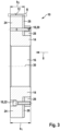
- Fig. 3 shows the rolling tool 10 from Fig. 2 along section AA.
- the profile area 12 in the area B is in the Figures 4 and 5 shown again enlarged.
- the rolling disk assembly 14 comprises a main disk 24 and an interchangeable disk 26 fastened thereto, which is positioned upstream of the main disk 24 with respect to the working direction 8.
- the interchangeable disk 26 is fastened to the main disk 24 by means of a clamping disk 28.
- the diameter of the clamping disk 28 is slightly smaller than the diameter of the main disk 24, so that there is no engagement with the workpiece.
- b 1 denotes a width of the rolling disk assembly 14.
- b 2 denotes a working width of the main disk 24 and the interchangeable disk 26 together.
- the fastening elements 18, which with reference to Fig. 2 described are designed here once as a pin 20 and once as a screw 22, for example a cylindrical pin and a cylinder head screw.
- the expert will expediently select the fastening elements 18 so that the individual disks of the rolling disk package 14 are fastened to one another sufficiently firmly.
- the anti-twist and anti-displacement devices are designed to be large enough to absorb static and dynamic forces from the work process.
- the detachability and assembly are determined so that the disks can be easily changed by the user, particularly preferably without special tools.
- the location and orientation of the fastening elements 18 are ideally coordinated so that the disks can be changed without having to remove the tool 10 from the rolling machine.
- the Figs. 4 and 5 show two different embodiments of rolling tools 10 in the enlarged area B of Fig. 3
- the embodiments differ in the design of the inlet regions 32 and in the presence/absence of a calibration region 34.
- the calibration region 34 is characterized by a constant profile along the working direction 8.
- Fig. 4 shows the rolling tool 10 with an inlet area 32 of width b 3 , a calibration area 34 of width b 4 and a downstream relief area 36 of width b 5 .
- the interchangeable disc may comprise only a portion of the inlet area 32.
- the main disc then also comprises a portion of the inlet area 32, as well as the calibration area 34 and the relief area 36.
- the interchangeable disc can encompass the entire inlet area 32.
- the main disc then encompasses the calibration area 34 and the relief area 36.
- the interchangeable disc can encompass the entire inlet area 32 and part of the calibration area 34.
- the main disc then encompasses the remaining part of the calibration area 34 and the relief area 36.
- the interchangeable disc can comprise the inlet area 32 and the entire calibration area 34.
- the main disc then comprises the relief area 36.
- the interchangeable disc can encompass the inlet area 32, the entire calibration area 34, and part of the relief area 36.
- the main disc then encompasses the remaining part of the relief area 36.
- the interchangeable disc has a chamfer 40 in which a profile depth of the teeth increases in the working direction.
- the chamfer 40 can, for example, comprise an increase in the profile from 0 to a maximum profile depth.
- the chamfer 40 does not begin at a profile depth of zero, but at a run-in depth t 1 , which, for example, is between one tenth and one half of the profile depth in the calibration area.
- the running-in depth t 1 is typically a value that results from half the difference between a pre-turning diameter and a root diameter.
- the increase in profile depth can be linear, as shown.
- the chamfer 40 can have a radius or steps, or even be designed in the form of a double chamfer.
- the chamfer 40 can be characterized by a chamfer angle w 1 , which, as can be seen from Fig. 4 as can be seen, as a tangent function of the inlet depth t 1 (assuming the profile depth starts at 0) and the width b 3 of the inlet area 32.
- the chamfer angle w 1 is preferably between 10° and 20°.
- the relief area 36 is arranged downstream of the calibration area 34 with respect to the working direction 8 and is characterized by a profile depression. Various embodiments known from the prior art are possible. Typically, the profile is machined at a relief angle w 3 .
- the relief angle w 3 is preferably between 0° 10' and 1°.
- Fig. 5 shows an alternative embodiment with inlet area 32 and relief area 36, i.e. without calibration area 34.
- a significant difference of the embodiment according to Fig. 5 compared to the embodiment according to Fig. 4 is the design of the inlet area 32.
- the inlet region 32 is formed by a profile depression 42.
- the profile depth t 2 is uniform across the width b 3 , but is incorporated with a first profile depression angle w 2 to the working direction.
- the region is therefore conical in shape compared to the calibration region 34.
- the first profile depression angle w 2 is preferably between 10° and 20°.
- Fig. 6 shows a rolling tool 10 according to a further embodiment of the invention.
- the illustration in Fig. 6 is analog Fig. 3 selected, whereby only the upper part of the rolling tool 10 was shown in section.
- the rolling tool 10 comprises a profile area 12, which is enlarged with surroundings C in Fig. 7 is shown.
- the rolling disk package 14 comprises in the embodiment according to Fig. 6 and Fig. 7
- a chamfering disc 44 which is arranged downstream of the main disc 24 with respect to the working direction 8. The workpiece 4 is thus first formed by the interchangeable disc 26, then by the main disc 24 and finally by the chamfering disc 44.
- Fig. 7 shows the area C in an enlarged view.
- the main disk 24, the interchangeable disk 26, and the chamfering disk 44 are shown in relation to the functional areas.
- the interchangeable disk 26 here, for example, exclusively comprises the inlet area 32 and no parts of the calibration area 34 or relief area 36.
- the main disk 24 here, purely for example, exclusively comprises a relief area 36 and also no calibration area 34.
- Other embodiments as described above are of course possible.
- the chamfering disc 44 featuring an oblique profile and a second profile depression angle w 4 .
- the first profile depression angle w 2 and the second profile depression angle w 4 can be the same or different.
- the profile depression angles w 2 and w 4 are different, since the second profile depression angle w 4 is determined by the component geometry.
- the second profile depression angle w 4 is between 2° and 10°.
- the rolling tool 10 shown is specially designed for workpieces 4 whose usable profile length or toothing length corresponds approximately to the width b 12 of the main disk 24.
- the workpiece 4 is rolled through the inlet area 32, then passes through the calibration area (not shown) and the relief area 36 of the main disk 24, if applicable, and is then guided over a part of the width b 14 of the chamfering disk 44.
- the chamfering disk 44 creates a chamfer of the profile on the workpiece 4.
Landscapes
- Engineering & Computer Science (AREA)
- Mechanical Engineering (AREA)
- Grinding And Polishing Of Tertiary Curved Surfaces And Surfaces With Complex Shapes (AREA)
- Rolling Contact Bearings (AREA)
Claims (10)
- Outil de laminage (10) pour le laminage d'un profilé (6) dans un processus de laminage par poussée, en particulier d'une denture de cannelure sur une pièce à usiner (4), comportant un bloc de disques de laminage (14) qui comprend au moins un disque principal (24) et un disque interchangeable (26) fixé sur celui-ci, dans lequel le disque interchangeable (26) est situé en amont du disque principal (24) par rapport à une direction de travail (8) qui est identifiée par une avance de la pièce à usiner, dans lequel le disque interchangeable (26) est fabriqué à partir du même matériau que le disque principal (24) ou d'un matériau différent et comprend une zone d'entrée (32) pour le laminage de la pièce à usiner (4), dans lequel le disque interchangeable (26) comporte un chanfrein (40) formant la zone d'entrée (32) ou une réduction de profil (42), et dans lequel le bloc de disques de laminage (14) comporte une zone de dégagement (36).
- Outil de laminage (10) selon la revendication 1, caractérisé en ce que le disque interchangeable (26) est fabriqué à partir d'un métal dur.
- Outil de laminage (10) selon l'une des revendications précédentes, caractérisé en ce qu'un premier angle de chanfreinage (w1) ou un angle de réduction de profil (w2) dans la zone d'entrée (32) est compris entre 5° et 35°, de préférence entre 10° et 20°, et est en particulier d'environ 15°.
- Outil de laminage (10) selon l'une des revendications précédentes, caractérisé en ce que le bloc de disques de laminage (14) comporte une zone de calibrage (34) qui est caractérisée par une hauteur de profil constante le long de la direction de travail (8).
- Outil de laminage (10) selon l'une des revendications précédentes, caractérisé en ce que le disque principal (24) comporte la zone de dégagement (36).
- Outil de laminage (10) selon l'une des revendications précédentes, caractérisé en ce que le bloc de disques de laminage (14) comprend un disque de chanfreinage (44) qui est caractérisé par une augmentation de profil le long de la direction de travail (8) et est situé en aval du disque principal (24) par rapport à la direction de travail (8).
- Outil de laminage (10) selon l'une des revendications précédentes, caractérisé en ce qu'un profil du disque principal (24) et/ou du disque interchangeable (26) est formé de la même manière dans un plan transversal.
- Ensemble de laminage (2) comportant au moins un, de préférence deux, trois ou quatre outils de laminage (10) formés de la même manière qui sont réalisés selon l'une des revendications précédentes, et comportant une commande qui est conçue pour rapprocher les outils de laminage (10) les uns des autres et pour permettre un déplacement axial de la pièce à usiner (4) vers les outils (10).
- Procédé de laminage d'un profilé (6), en particulier d'une denture de cannelure sur une pièce à usiner (4), au moyen d'un outil de laminage (10) selon l'une des revendications 1 à 7 précédentes, dans lequel, lors d'un formage de la pièce à usiner (4), un rapprochement axial de la pièce à usiner (4) vers l'outil de laminage (10) a lieu le long d'une direction de travail (8) qui est identifiée par une avance de la pièce à usiner, caractérisé en ce que le profilé (6) est formé dans la zone d'entrée (32), une zone de calibrage facultative (34) et la zone de dégagement (36) de l'outil de laminage (10).
- Procédé selon la revendication 9, dans lequel le rapprochement de la pièce à usiner (4) vers l'outil de laminage (10) le long de la direction de travail (8) est un mouvement d'avance à vitesse d'avance constante ou variable.
Applications Claiming Priority (2)
| Application Number | Priority Date | Filing Date | Title |
|---|---|---|---|
| DE102020103151.3A DE102020103151A1 (de) | 2020-02-07 | 2020-02-07 | Walzwerkzeug und Verfahren zum Walzen eines Profils |
| PCT/EP2021/052643 WO2021156355A1 (fr) | 2020-02-07 | 2021-02-04 | Outil de laminage et procédé de laminage d'un profilé |
Publications (3)
| Publication Number | Publication Date |
|---|---|
| EP4100186A1 EP4100186A1 (fr) | 2022-12-14 |
| EP4100186C0 EP4100186C0 (fr) | 2025-04-02 |
| EP4100186B1 true EP4100186B1 (fr) | 2025-04-02 |
Family
ID=74595258
Family Applications (1)
| Application Number | Title | Priority Date | Filing Date |
|---|---|---|---|
| EP21705114.3A Active EP4100186B1 (fr) | 2020-02-07 | 2021-02-04 | Outil de laminage et procédé de laminage d'un profilé |
Country Status (4)
| Country | Link |
|---|---|
| EP (1) | EP4100186B1 (fr) |
| DE (1) | DE102020103151A1 (fr) |
| HU (1) | HUE071839T2 (fr) |
| WO (1) | WO2021156355A1 (fr) |
Families Citing this family (3)
| Publication number | Priority date | Publication date | Assignee | Title |
|---|---|---|---|---|
| DE102023110654A1 (de) | 2023-04-26 | 2024-10-31 | Osg Ex-Cell-O Gmbh | Rundwalzwerkzeug und Verfahren zur Herstellung Profilierung |
| EP4477334A1 (fr) * | 2023-06-15 | 2024-12-18 | Profiroll Technologies GmbH | Laminoir, système et procédé de laminage d'un profil orienté longitudinalement |
| DE102023128274A1 (de) | 2023-10-16 | 2025-04-17 | Profiroll Technologies Gmbh | Profil-Querwalzverfahren zur Erzeugung eines Verzahnungsprofils mit Formelementen im Profileinlauf an einem Werkstück |
Family Cites Families (12)
| Publication number | Priority date | Publication date | Assignee | Title |
|---|---|---|---|---|
| DE51257C (de) * | 1889-07-05 | 1890-03-19 | THE SlMONDS STEEL AND IRON FORGING COMPANY LIMITED in London | Walzplatten zur Herstellung von Schraubengewinden |
| DE925522C (de) * | 1950-10-20 | 1955-04-21 | Pee Wee Maschinen Und Appbau I | Verfahren, Gewindewalzen und Maschine zum Walzen von Gewinde im Durchlauf |
| DE803232C (de) | 1951-04-02 | 1951-04-02 | Schoppe & Faeser Feinmechanik | Vorrichtung zum Herstellen von Zahnraedern und verzahnten Teilen nach dem Warmrollverfahren |
| DE1013612B (de) * | 1953-03-12 | 1957-08-14 | Pee Wee Maschinen Und Appbau I | Einrichtung zum Kaltwalzen von achsparallelen Profilen, z.B. Verzahnungen |
| US3735619A (en) * | 1972-01-27 | 1973-05-29 | Lear Siegler Inc | Gear roll chamfering |
| JPS57160532A (en) * | 1981-03-25 | 1982-10-02 | Anderson Cook Inc | Rotary molding tool and spindle for said tool |
| CN2356779Y (zh) * | 1998-07-16 | 2000-01-05 | 王雪云 | 变齿形螺旋轴向进给滚丝模 |
| DE10129853C1 (de) | 2001-06-21 | 2003-01-09 | Gleason Works | Werkzeug zum Anfasen und Entgraten der stirnseitigen Zahnkanten von Zahnrädern |
| DE102007039959B4 (de) | 2007-08-23 | 2013-06-06 | Profiroll Technologies Gmbh | Verfahren zum Kaltwalzen von längsgerichteten Verzahnungen und Profilen bei langen wellenförmigen Werkstücken und Profilwalzmaschine hierzu |
| JP5401667B2 (ja) * | 2007-10-12 | 2014-01-29 | 有希 安藤 | 転造ネジ軸の製造方法 |
| JP5053399B2 (ja) * | 2010-02-22 | 2012-10-17 | ユニオンツール株式会社 | 転造ダイス |
| DE102017116895B4 (de) * | 2017-07-26 | 2024-12-05 | Osg Ex-Cell-O Gmbh | Verfahren und Vorrichtung zur Herstellung einer Verzahnung an einem zylindrischen Werkstück |
-
2020
- 2020-02-07 DE DE102020103151.3A patent/DE102020103151A1/de active Pending
-
2021
- 2021-02-04 HU HUE21705114A patent/HUE071839T2/hu unknown
- 2021-02-04 WO PCT/EP2021/052643 patent/WO2021156355A1/fr not_active Ceased
- 2021-02-04 EP EP21705114.3A patent/EP4100186B1/fr active Active
Also Published As
| Publication number | Publication date |
|---|---|
| EP4100186C0 (fr) | 2025-04-02 |
| DE102020103151A1 (de) | 2021-08-12 |
| WO2021156355A1 (fr) | 2021-08-12 |
| EP4100186A1 (fr) | 2022-12-14 |
| HUE071839T2 (hu) | 2025-09-28 |
Similar Documents
| Publication | Publication Date | Title |
|---|---|---|
| EP2665574B1 (fr) | Procédé d'usinage d'une pièce par enlèvement de copeaux, et machine-outil mise au point à cette fin | |
| EP2385885B1 (fr) | Dispositif et procédé pour tailler des dents dans des pièces et jeu d'outils correspondant | |
| DE10330474B4 (de) | Vorrichtung zur Herstellung eines Zahnrads aus einem Zahnradrohling | |
| EP1987919B1 (fr) | Procédé et meuleuse destinés à profiler un outil de rectification | |
| EP3651925B1 (fr) | Procédé pour produire une pièce dentée, ainsi que programme de commande, outils et machine à former les dentures adaptés audit procédé | |
| EP3154733B1 (fr) | Procédé de formation de contre-dépouilles dans les flancs de dents de roues dentées et machine-outil pour sa mise en oeuvre | |
| EP3546101B1 (fr) | Procédé et dispositif servant à tailler des roues d'usinage par décolletage en développante | |
| EP4100186B1 (fr) | Outil de laminage et procédé de laminage d'un profilé | |
| DE3905168C1 (fr) | ||
| DE102007039959B4 (de) | Verfahren zum Kaltwalzen von längsgerichteten Verzahnungen und Profilen bei langen wellenförmigen Werkstücken und Profilwalzmaschine hierzu | |
| EP1442808B1 (fr) | Matrice de laminage | |
| EP2537616B1 (fr) | Procédé robuste de taillage de cylindres et dispositif correspondant doté d'un outil de taillage de cylindres | |
| DE102020001428A1 (de) | Verfahren zur Zahnkantenbearbeitung | |
| DE20320294U1 (de) | Vorrichtung zur Herstellung eines Zahnrads | |
| EP0711620A1 (fr) | Fraise pour une machine à fraiser les essieux | |
| DE102007060554A1 (de) | Verfahren und Werkzeug zur Erzeugung eines Außengewindes | |
| EP3246104B1 (fr) | Procede et dispositif de fabrication d'une piece de formage | |
| DE1138013B (de) | Verfahren und Vorrichtung zum Herstellen von an ihrem Umfang im wesentlichen laengsprofilierten zylindrischen Werkstuecken | |
| DE102021002704A1 (de) | Verfahren zur verzahnungsbearbeitung, insbesondere zur zahnkantenbearbeitung | |
| EP3016771B1 (fr) | Dispositif permettant de lisser une denture et procédé de production d'une denture | |
| EP2363228A2 (fr) | Outil et procédé de fabrication d'un arbre | |
| WO2017063730A1 (fr) | Procédé d'usinage d'une denture ainsi qu'ensemble, outil d'usinage et machine-outil associés | |
| EP2483027B1 (fr) | Procédé de fabrication d'une denture intérieure | |
| EP3414030B1 (fr) | Dispositif de galetage de pièces munies d'une denture et procédé afférent | |
| EP3976303B1 (fr) | Fraise à tailler des engrenages et procédé pour fabriquer un engrenage à double denture hélicoïdale, ainsi qu'utilisation de la fraise à tailler des engrenages pour produire l'engrenage à double denture hélicoïdale |
Legal Events
| Date | Code | Title | Description |
|---|---|---|---|
| STAA | Information on the status of an ep patent application or granted ep patent |
Free format text: STATUS: UNKNOWN |
|
| STAA | Information on the status of an ep patent application or granted ep patent |
Free format text: STATUS: THE INTERNATIONAL PUBLICATION HAS BEEN MADE |
|
| PUAI | Public reference made under article 153(3) epc to a published international application that has entered the european phase |
Free format text: ORIGINAL CODE: 0009012 |
|
| STAA | Information on the status of an ep patent application or granted ep patent |
Free format text: STATUS: REQUEST FOR EXAMINATION WAS MADE |
|
| 17P | Request for examination filed |
Effective date: 20220630 |
|
| AK | Designated contracting states |
Kind code of ref document: A1 Designated state(s): AL AT BE BG CH CY CZ DE DK EE ES FI FR GB GR HR HU IE IS IT LI LT LU LV MC MK MT NL NO PL PT RO RS SE SI SK SM TR |
|
| DAV | Request for validation of the european patent (deleted) | ||
| DAX | Request for extension of the european patent (deleted) | ||
| GRAP | Despatch of communication of intention to grant a patent |
Free format text: ORIGINAL CODE: EPIDOSNIGR1 |
|
| STAA | Information on the status of an ep patent application or granted ep patent |
Free format text: STATUS: GRANT OF PATENT IS INTENDED |
|
| INTG | Intention to grant announced |
Effective date: 20240916 |
|
| GRAS | Grant fee paid |
Free format text: ORIGINAL CODE: EPIDOSNIGR3 |
|
| GRAA | (expected) grant |
Free format text: ORIGINAL CODE: 0009210 |
|
| STAA | Information on the status of an ep patent application or granted ep patent |
Free format text: STATUS: THE PATENT HAS BEEN GRANTED |
|
| AK | Designated contracting states |
Kind code of ref document: B1 Designated state(s): AL AT BE BG CH CY CZ DE DK EE ES FI FR GB GR HR HU IE IS IT LI LT LU LV MC MK MT NL NO PL PT RO RS SE SI SK SM TR |
|
| REG | Reference to a national code |
Ref country code: GB Ref legal event code: FG4D Free format text: NOT ENGLISH |
|
| REG | Reference to a national code |
Ref country code: CH Ref legal event code: EP |
|
| REG | Reference to a national code |
Ref country code: IE Ref legal event code: FG4D Free format text: LANGUAGE OF EP DOCUMENT: GERMAN |
|
| U01 | Request for unitary effect filed |
Effective date: 20250402 |
|
| U07 | Unitary effect registered |
Designated state(s): AT BE BG DE DK EE FI FR IT LT LU LV MT NL PT RO SE SI Effective date: 20250408 |
|
| REG | Reference to a national code |
Ref country code: HU Ref legal event code: AG4A Ref document number: E071839 Country of ref document: HU |
|
| PG25 | Lapsed in a contracting state [announced via postgrant information from national office to epo] |
Ref country code: ES Free format text: LAPSE BECAUSE OF FAILURE TO SUBMIT A TRANSLATION OF THE DESCRIPTION OR TO PAY THE FEE WITHIN THE PRESCRIBED TIME-LIMIT Effective date: 20250402 |
|
| PG25 | Lapsed in a contracting state [announced via postgrant information from national office to epo] |
Ref country code: GR Free format text: LAPSE BECAUSE OF FAILURE TO SUBMIT A TRANSLATION OF THE DESCRIPTION OR TO PAY THE FEE WITHIN THE PRESCRIBED TIME-LIMIT Effective date: 20250703 Ref country code: NO Free format text: LAPSE BECAUSE OF FAILURE TO SUBMIT A TRANSLATION OF THE DESCRIPTION OR TO PAY THE FEE WITHIN THE PRESCRIBED TIME-LIMIT Effective date: 20250702 |
|
| PG25 | Lapsed in a contracting state [announced via postgrant information from national office to epo] |
Ref country code: PL Free format text: LAPSE BECAUSE OF FAILURE TO SUBMIT A TRANSLATION OF THE DESCRIPTION OR TO PAY THE FEE WITHIN THE PRESCRIBED TIME-LIMIT Effective date: 20250402 |
|
| PG25 | Lapsed in a contracting state [announced via postgrant information from national office to epo] |
Ref country code: HR Free format text: LAPSE BECAUSE OF FAILURE TO SUBMIT A TRANSLATION OF THE DESCRIPTION OR TO PAY THE FEE WITHIN THE PRESCRIBED TIME-LIMIT Effective date: 20250402 |
|
| PG25 | Lapsed in a contracting state [announced via postgrant information from national office to epo] |
Ref country code: RS Free format text: LAPSE BECAUSE OF FAILURE TO SUBMIT A TRANSLATION OF THE DESCRIPTION OR TO PAY THE FEE WITHIN THE PRESCRIBED TIME-LIMIT Effective date: 20250702 |
|
| PG25 | Lapsed in a contracting state [announced via postgrant information from national office to epo] |
Ref country code: IS Free format text: LAPSE BECAUSE OF FAILURE TO SUBMIT A TRANSLATION OF THE DESCRIPTION OR TO PAY THE FEE WITHIN THE PRESCRIBED TIME-LIMIT Effective date: 20250802 |
|
| PG25 | Lapsed in a contracting state [announced via postgrant information from national office to epo] |
Ref country code: SM Free format text: LAPSE BECAUSE OF FAILURE TO SUBMIT A TRANSLATION OF THE DESCRIPTION OR TO PAY THE FEE WITHIN THE PRESCRIBED TIME-LIMIT Effective date: 20250402 |
|
| PG25 | Lapsed in a contracting state [announced via postgrant information from national office to epo] |
Ref country code: CZ Free format text: LAPSE BECAUSE OF FAILURE TO SUBMIT A TRANSLATION OF THE DESCRIPTION OR TO PAY THE FEE WITHIN THE PRESCRIBED TIME-LIMIT Effective date: 20250402 |
|
| PG25 | Lapsed in a contracting state [announced via postgrant information from national office to epo] |
Ref country code: SK Free format text: LAPSE BECAUSE OF FAILURE TO SUBMIT A TRANSLATION OF THE DESCRIPTION OR TO PAY THE FEE WITHIN THE PRESCRIBED TIME-LIMIT Effective date: 20250402 |
|
| PLBE | No opposition filed within time limit |
Free format text: ORIGINAL CODE: 0009261 |
|
| STAA | Information on the status of an ep patent application or granted ep patent |
Free format text: STATUS: NO OPPOSITION FILED WITHIN TIME LIMIT |
|
| REG | Reference to a national code |
Ref country code: CH Ref legal event code: L10 Free format text: ST27 STATUS EVENT CODE: U-0-0-L10-L00 (AS PROVIDED BY THE NATIONAL OFFICE) Effective date: 20260211 |
|
| 26N | No opposition filed |
Effective date: 20260105 |
|
| PGFP | Annual fee paid to national office [announced via postgrant information from national office to epo] |
Ref country code: HU Payment date: 20260226 Year of fee payment: 6 |