EP4100150B1 - Filtervorrichtung zum filtern eines fluids und verfahren zum filtern eines fluids - Google Patents
Filtervorrichtung zum filtern eines fluids und verfahren zum filtern eines fluids Download PDFInfo
- Publication number
- EP4100150B1 EP4100150B1 EP21729287.9A EP21729287A EP4100150B1 EP 4100150 B1 EP4100150 B1 EP 4100150B1 EP 21729287 A EP21729287 A EP 21729287A EP 4100150 B1 EP4100150 B1 EP 4100150B1
- Authority
- EP
- European Patent Office
- Prior art keywords
- filter
- filter unit
- bed
- filtration
- filtering
- Prior art date
- Legal status (The legal status is an assumption and is not a legal conclusion. Google has not performed a legal analysis and makes no representation as to the accuracy of the status listed.)
- Active
Links
Images


Classifications
-
- B—PERFORMING OPERATIONS; TRANSPORTING
- B01—PHYSICAL OR CHEMICAL PROCESSES OR APPARATUS IN GENERAL
- B01D—SEPARATION
- B01D61/00—Processes of separation using semi-permeable membranes, e.g. dialysis, osmosis or ultrafiltration; Apparatus, accessories or auxiliary operations specially adapted therefor
- B01D61/14—Ultrafiltration; Microfiltration
- B01D61/18—Apparatus therefor
-
- A—HUMAN NECESSITIES
- A23—FOODS OR FOODSTUFFS; TREATMENT THEREOF, NOT COVERED BY OTHER CLASSES
- A23L—FOODS, FOODSTUFFS OR NON-ALCOHOLIC BEVERAGES, NOT OTHERWISE PROVIDED FOR; PREPARATION OR TREATMENT THEREOF
- A23L2/00—Non-alcoholic beverages; Dry compositions or concentrates therefor; Preparation or treatment thereof
- A23L2/70—Clarifying or fining of non-alcoholic beverages; Removing unwanted matter
- A23L2/72—Clarifying or fining of non-alcoholic beverages; Removing unwanted matter by filtration
- A23L2/74—Clarifying or fining of non-alcoholic beverages; Removing unwanted matter by filtration using membranes, e.g. osmosis, ultrafiltration
-
- B—PERFORMING OPERATIONS; TRANSPORTING
- B01—PHYSICAL OR CHEMICAL PROCESSES OR APPARATUS IN GENERAL
- B01D—SEPARATION
- B01D61/00—Processes of separation using semi-permeable membranes, e.g. dialysis, osmosis or ultrafiltration; Apparatus, accessories or auxiliary operations specially adapted therefor
- B01D61/58—Multistep processes
-
- B—PERFORMING OPERATIONS; TRANSPORTING
- B01—PHYSICAL OR CHEMICAL PROCESSES OR APPARATUS IN GENERAL
- B01F—MIXING, e.g. DISSOLVING, EMULSIFYING OR DISPERSING
- B01F27/00—Mixers with rotary stirring devices in fixed receptacles; Kneaders
- B01F27/05—Stirrers
- B01F27/11—Stirrers characterised by the configuration of the stirrers
- B01F27/115—Stirrers characterised by the configuration of the stirrers comprising discs or disc-like elements essentially perpendicular to the stirrer shaft axis
- B01F27/1151—Stirrers characterised by the configuration of the stirrers comprising discs or disc-like elements essentially perpendicular to the stirrer shaft axis with holes on the surface
-
- B—PERFORMING OPERATIONS; TRANSPORTING
- B01—PHYSICAL OR CHEMICAL PROCESSES OR APPARATUS IN GENERAL
- B01F—MIXING, e.g. DISSOLVING, EMULSIFYING OR DISPERSING
- B01F27/00—Mixers with rotary stirring devices in fixed receptacles; Kneaders
- B01F27/05—Stirrers
- B01F27/11—Stirrers characterised by the configuration of the stirrers
- B01F27/118—Stirrers in the form of brushes, sieves, grids, chains or springs
-
- B—PERFORMING OPERATIONS; TRANSPORTING
- B01—PHYSICAL OR CHEMICAL PROCESSES OR APPARATUS IN GENERAL
- B01F—MIXING, e.g. DISSOLVING, EMULSIFYING OR DISPERSING
- B01F27/00—Mixers with rotary stirring devices in fixed receptacles; Kneaders
- B01F27/23—Mixers with rotary stirring devices in fixed receptacles; Kneaders characterised by the orientation or disposition of the rotor axis
- B01F27/231—Mixers with rotary stirring devices in fixed receptacles; Kneaders characterised by the orientation or disposition of the rotor axis with a variable orientation during mixing operation, e.g. with tiltable rotor axis
- B01F27/2312—Mixers with rotary stirring devices in fixed receptacles; Kneaders characterised by the orientation or disposition of the rotor axis with a variable orientation during mixing operation, e.g. with tiltable rotor axis the position of the rotating shaft being adjustable in the interior of the receptacle, e.g. to locate the stirrer in different locations during the mixing
-
- B—PERFORMING OPERATIONS; TRANSPORTING
- B01—PHYSICAL OR CHEMICAL PROCESSES OR APPARATUS IN GENERAL
- B01F—MIXING, e.g. DISSOLVING, EMULSIFYING OR DISPERSING
- B01F27/00—Mixers with rotary stirring devices in fixed receptacles; Kneaders
- B01F27/80—Mixers with rotary stirring devices in fixed receptacles; Kneaders with stirrers rotating about a substantially vertical axis
- B01F27/805—Mixers with rotary stirring devices in fixed receptacles; Kneaders with stirrers rotating about a substantially vertical axis wherein the stirrers or the receptacles are moved in order to bring them into operative position; Means for fixing the receptacle
- B01F27/806—Mixers with rotary stirring devices in fixed receptacles; Kneaders with stirrers rotating about a substantially vertical axis wherein the stirrers or the receptacles are moved in order to bring them into operative position; Means for fixing the receptacle with vertical displacement of the stirrer, e.g. in combination with means for pivoting the stirrer about a vertical axis in order to co-operate with different receptacles
-
- B—PERFORMING OPERATIONS; TRANSPORTING
- B01—PHYSICAL OR CHEMICAL PROCESSES OR APPARATUS IN GENERAL
- B01F—MIXING, e.g. DISSOLVING, EMULSIFYING OR DISPERSING
- B01F27/00—Mixers with rotary stirring devices in fixed receptacles; Kneaders
- B01F27/80—Mixers with rotary stirring devices in fixed receptacles; Kneaders with stirrers rotating about a substantially vertical axis
- B01F27/93—Mixers with rotary stirring devices in fixed receptacles; Kneaders with stirrers rotating about a substantially vertical axis with rotary discs
-
- C—CHEMISTRY; METALLURGY
- C12—BIOCHEMISTRY; BEER; SPIRITS; WINE; VINEGAR; MICROBIOLOGY; ENZYMOLOGY; MUTATION OR GENETIC ENGINEERING
- C12H—PASTEURISATION, STERILISATION, PRESERVATION, PURIFICATION, CLARIFICATION OR AGEING OF ALCOHOLIC BEVERAGES; METHODS FOR ALTERING THE ALCOHOL CONTENT OF FERMENTED SOLUTIONS OR ALCOHOLIC BEVERAGES
- C12H1/00—Pasteurisation, sterilisation, preservation, purification, clarification, or ageing of alcoholic beverages
- C12H1/02—Pasteurisation, sterilisation, preservation, purification, clarification, or ageing of alcoholic beverages combined with removal of precipitate or added materials, e.g. adsorption material
- C12H1/06—Precipitation by physical means, e.g. by irradiation, vibrations
- C12H1/063—Separation by filtration
-
- B—PERFORMING OPERATIONS; TRANSPORTING
- B01—PHYSICAL OR CHEMICAL PROCESSES OR APPARATUS IN GENERAL
- B01D—SEPARATION
- B01D2311/00—Details relating to membrane separation process operations and control
- B01D2311/06—Specific process operations in the permeate stream
Definitions
- the present invention refers to a filtering device for filtering a fluid as specified in claim 1 .
- the purpose of the filtering device of the present invention may be in a first aspect to filter a fluid containing dissolved and optionally colloidal substances, and possibly further impurities.
- a second important aspect of the present invention is to recoup valuable substances, which are retained in at least one of the filter units and which thereafter are recovered from the respective retentate and/or from the filter material of the respective filter unit.
- the present invention further refers to a process as specified in claim 6, for filtering a fluid, containing dissolved and optionally colloidal substances, and/or further impurities, by means of a filtering device wherein said fluid is a liquid, which is filtered in a filtering device with the features mentioned above.
- US 8,361,321 B2 focuses on water treatment.
- the filter consists of individual graphene sheets, with porosity such as to allow the deionization of water, as well as the separation of chlorine, and then sodium.
- porosity such as to allow the deionization of water, as well as the separation of chlorine, and then sodium.
- the process known from this document fore sees two graphene sheets inserted in series with different sizes/porosity, precisely to allow the extraction of molecules of different sizes.
- the system provided for by the US patent does not take into account the detection of anti-clogging systems.
- this prior art is not concerned with the solutions that are necessary to solve the problems that are typically found when proceeding with filtration of liquids, which are not water, and therefore contain substances that could clog the system.
- WO 2018/078427 A1 describes a graphene-based filtering element comprising a blend of mesoporous graphene compound having pores with average pore size between 0,4 and 250 nm and at least one spacing material in granular form.
- the graphene-based compound is present as nanoplatelets, sheets or plates of graphene, functionalized graphene or graphene oxide.
- the filtering material consists of said graphene-based material which is mixed with a spacing material and homogeneously dispersed in a liquid phase.
- the spacing material can be selected from activated carbon, zeolites, sand, alumina, aluminum silicate and the like.
- the spacing material is in granular form with a particle size of about 0,1 mm to 6 mm and its purpose is to avoid the adhesion of the graphene sheets.
- Said combined filter material is useful for the removal of contaminants from a fluid, for instance waste water, blood or fruit juice.
- US 2011/0114573 A1 describes a filtration apparatus with a containment device, like a housing or a cartridge, where the filtration media is located (and within which a fluid passes through).
- the filtration media is disposed within the housing either as a homogeneous mixture, or as individual components in discrete predetermined locations. Either way the filtration media is effectively blocked in a given position.
- the figures accompanying the said US patent depict a close cartridge with a closed top, where the filtration material is compressed within predefined locations.
- WO 2015/034776 A1 to Zenbury discloses a system for producing clarified citrus juice concentrates, where peels and segments are enzymatically digested and subjected to a grinder, water adder, centrigue filter series.
- WO 2012/040574 A1 to Xcellerex discloses a chromatography system, wherein a flexible container is fit within a support structure and adapted to receive a filtration or absorptive chromatography resin.
- a rotating agitator By rotating the agitator, same produces a pressure upbuild towards the flexible container, so that the flexible container remains stable.
- the agitator offers two positions of operation. In the upper position, it is meant to leave the filter bed untouched. In the bottom position, the agitator produces a slurry configuration.
- Said prior art documentation is silent about regeneration of the filter material and cleaning of the filter element, hence the system, which occurs regularly during various working phases and cycles of the filtration (so it is a normal working phase of the process) but it may also be relevant after the system has been used for a certain period of time, especially when the system is aimed at liquid (not water) purification or filtration.
- certain phases including when changes of pressure occur, e.g. when the system is started and or stopped, or over some time after normal use, the filter material becomes unstable, clogging occurs, and preferential pathways are created in the filter material. This affects adversely the efficiency of the filtering process.
- the filter material disintegrates and releases micro-particles that impurify the filtrate, which as explained below cause also inefficiencies, first of all product loss, and further costs in terms of disposal of the impurities and/or purchase and reintegration of the filter bed material.
- WO 2015/034776 A1 concerns a device for filtering beverages with a first filter unit, which is an ultrafiltration, a second filter unit, which is a molecular sieve, and a third filter unit, which is a reverse osmosis arrangement.
- the second filter unit contains an ion exchange medium, particularly a base resin or an acid ion exchange material. This document is silent about a mixing device for the material of the second filter unit and resins, which are used as an ion exchange medium, typically are not mixed. Furthermore there is no plate to pressurize the filter medium or any other device to change the pressure within the filter units.
- CN 109 418 680 A describes a process for deacidification and debittering of a juice in a tank by means of an adsorption resin, which is filled between an upper filter screen and a lower filter screen, wherein two stirring blades on a stirring shaft are used to evenly disperse the resin in the juice to be treated. Because of the fact that the stirring blades are disposed between the two filter screens it is not possible to move the mixing device in an axial direction.
- Subject-matter of the present invention thus is, according to a first aspect, a filtering device for filtering a fluid (a liquid) containing dissolved and optionally colloidal substances and/or other impurities, with at least three filter units with the features mentioned above, wherein the filtering device comprises a rotatable mixing device within a receptacle containing the second filter unit, arranged above the filter bed and/or in the upper zone of the filter bed, within the filter bed, and wherein the rotatable mixing device is moveable within the receptacle in an axial direction relative to the upper zone of the filter bed, and with the further features of claim 1.
- the filter bed of the second filter unit comprises at least one particle filter material of the group comprising, graphene and activated carbon.
- the primary advantages of the mixing device for the filter bed in the second filter unit are that on one hand it may stir and agitate the filter bed, and on the other hand the axially moveable mixing device is able to pre-compress the filter bed.
- the invention provides a mixer or stirrer which breaks up the filtering bed and recompacts it naturally or forcibly thanks to pre-compression depending on the product or compound.
- the specific mixing device consists of a perforated plate with knives or blades, and depending on the position of the plate it makes it possible to create a more or less important pressure on the material of the filter bed.
- the filtering device comprises a rotatable mixing device within a receptacle containing the second filter unit, above the filter bed or in the upper zone of the filter bed.
- the rotation of the mixing device generally will not be continuous, but it is sufficient to carry out the rotation in certain phases.
- the mixing device can have other purposes than the mixing of the particles of the filter bed. When the device is in the filtration mode the upper part of the filter bed can be levelled in order to make the upper surface of the filter bed homogeneous and distribute the pressures evenly. A second purpose is to hold the filtering bed in the vacuum phase, wherein a low pressure is created in the space above the filter bed.
- the mixing device is adapted only to mix the granules in the upper region of the filter bed thereby eliminating preferential pathways in the filter bed material which would compromise an efficient filter action.
- the pressure drop and load difference in the second filter unit can vary, depending on the variation of the compounds used for the filter bed and/or specific requirements.
- a pressure diagram it can be shown, how much pressure a liquid needs to pass through the filtering layer, whereby the invention uses a kind of physical filtration in the second filter unit, which is different to ion exchange systems used in the prior art.
- This pressure can be provided by the fluid or with the help of a plate, which is part of the mixing device and which is axially moveable, which, as it descends, creates additional pressure (a preload) on the fluid.
- the pressure inside the filtering bed of the second filter unit can for instance also be managed with the pressure drop of the membrane of the third filter unit or with the closing of valves at the filter outlet.
- a plate on the mixing device which compacts the filter bed is not necessary, still provided though, because the pressure drop is very high, on others, such as carbon with a high graphene content, being lighter, it is advantageous to increase the pressure drop.
- the pressure load can be managed dynamically with the respective speed of movement of the mixing device pressing the filter bed, depending to the flow or during the duration of the filtration process.
- the filter bed By means of a plate of the mixing device or a combination of several devices (pump, valves etc.) the filter bed can be preloaded during filtration, while during regeneration the preload can be removed and the filter bed can be mixed or broken to improve and ensure the cleaning or regeneration of the filter material.
- the vertical pressure or preloading can be adjustable depending on the material used in the filter bed, whether it works under pressure, or a vacuum may be used to keep the filter bed down.
- Regeneration of the filter bed can be carried out using chemical detergents or natural and non-chemical solvents, such as for example ethyl alcohol, glycerol or high oleic oil.
- the filtering device can be operated in equal current even during regeneration and preferably always in the same flow direction, with the flow from top to bottom of the receptacle, thereby removing all probability of air bubbles, which could generate preferential pathways.
- the filter bed is excessively pressed and needs to be washed or regenerated by removing the pre-charge and mixing or breaking the blockage generated by the pressure, the system can be restored and the pressure drop can be brought back to lower or factory values.
- the filtration media of the filter bed of the second filter unit is open in its top region, in particular the filtration media is not compressed from above, which means preferably there is a void above the filter bed between the filter bed itself and any further structure which forms part of the receptacle, which receives the filter bed, i.e., which forms a housing for the filter bed.
- Such an 'open on top' concept differentiates the present invention from traditional filter beds, that are compressed within a cartridge.
- the invention creates the possibility to decide the level of pressure to be applied to the filter bed.
- the rotatable mixing device comprises a perforated plate with holes and/or slots and a system of stirring knives on the lower side of said plate serve as the mixing device.
- These stirring elements break up the filter bed of the filter unit and the device recompacts it naturally or forcibly thanks to pre-compression by the perforated plate, which, depending on its position can create a more or less important pressure on the filter bed.
- a circular plate preferably is used.
- the contour of the plate is adapted in accordance with the section of the receptacle.
- the plate and the mixing device con rotate and move axially (upwards and downwards) for instance by means of a hydraulic or pneumatic device, such as a piston, or a mechanical device, such as a gear unit, or a spindle, or even two or more drive units of this kind.
- a hydraulic or pneumatic device such as a piston
- a mechanical device such as a gear unit, or a spindle
- the purpose of the axially moveable plate is to pre-compress the material. Some materials require only agitation by the mixing device, some only pre-compression and some require both.
- the rotation of the mixing device may be non-continuous and it may rotate for instance only when the preload pressure on the filter bed is removed. Alternatively, instead of the agitation, there can be pressure back on. Predominantly a slow rotation speed of the mixing device is recommended in order to avoid breaking of the filter material. If during a certain phase only mixing is intended, the mixing can take place continuously. If, however, the mixing device shall deliver pre-compression, the mixing device preferably works, when the pre-compression is removed and the filter bed is free to move.
- first filter unit molecules of more relevant dimensions are removed, such as colour or polyphenols or colloids, since these molecules, if not preliminarily removed, could clog or limit the adsorbing capacity of the filter material of the second filer unit and would progressively reduce the effectiveness of the entire filtration process.
- first filter stage may include a preliminary roughing stage, with for instance the effect of removing superfluous parts from a material in its rough state to prepare it for further processing.
- the solution is treated with a membrane.
- This first filter unit may comprise a microfiltration and/or an ultrafiltration and/or a nanofiltration and/or a reverse osmosis membrane which serves to have an initial separation between the solution and the components that are to be retained based on their molecular weight.
- the solution is separated into two parts, the retentate or concentrate which contains most of the pigment components and colloidal substances, whereas the permeate of the first filter unit contains mainly low molecular weight molecules such as for instance salts, acid sugars and a small part of pigments. These components can be removed in the second filter unit.
- either the permeate or the retentate may be injected into the second filter unit.
- the retentate may also contain valuable substances and the present invention includes the possibility to recover such valuable substances, which are retained by the filter, particularly as by products as for instance malic acid or polyphenols.
- Microfiltration membranes usually are adapted to separate molecules with a size of between about 5 ⁇ m to 0.1 ⁇ m.
- Ultrafiltration membranes usually are adapted for the separation of molecules with a molecular weight between 300,000 and 10,000 Daltons and/or a size between about 0.1 ⁇ m to 0.03 ⁇ m.
- Nanofiltration membranes usually allow the separation of molecules with a molecular weight in a range between 10,000 and 200 Daltons, depending on their respective pore size.
- Lamellar membranous atomic layer material adopted for this invention based on carbon, graphene, graphite or other nanocomposite material allow the separation of molecules between about 400 and 150 Daltons.
- other materials may be applied for the membranes, hence enabling separation of substances of an even inferior dimension down to 0.3 nm, i.e. 3 Armstrong.
- the second filter unit is particularly suitable to adsorb or absorb and retain certain types of particles with molecular weights over, for example, 350 Daltons, but it may adsorb or absorb and retain much smaller molecules, depending on the material(s) that individually or in combination constitute the filtration media for the filtration bed.
- the second filter unit can be designed to work with aggressive or non-aggressive materials, for instance food related materials, even with high alcohol content, both at low and very hot temperatures, with pressures that can reach preferably up to 40 bar.
- the particles retained by the filter bed of the second filter unit can be recovered by an acidic or alcoholic alkaline solvent and recovered in a third phase by separation or distillation.
- the third filter unit in turn primarily has the purpose to remove micro and/or nano-particles which may be generated by disintegration of the filter bed material of the second filter unit.
- the filtering system is designed to contain reusable filter bed material without the need to dispose said material and thereby saves costs, time and space, while, as said reducing product losses.
- the specific adsorbent or absorbent material of the filter bed of the second filter unit according to the present invention has a similar function like a membrane and is suitable for different types of low or high density nanocomponents with greater absorbent power, for example activated carbon, graphene, zeolites.
- the adsorbent or absorbent material of the second filter unit can comprise particles of different size without the danger of releasing any particles into the final product, because the third filter unit is disposed downstream of the second filter unit.
- the present invention focuses on liquid filtration, where the liquid contains larger molecular weight substances (compared to the substances contained in the water). As such, the substances may clog the membrane, which in turn requires regular cleaning and regeneration, which in concrete means stopping and restarting the system, hence changing pressure, at regular intervals. These regular pressure and condition changes in turn do create pathways, which unless tackled with appropriate devices and solutions, ultimately affect the entire performance and integration of the filtration system.
- the filtration system according to the present invention can also be used for filtering air or gases, for instance an airflow which is contaminated with bacteria and/or virus.
- the filtration device could for example operate similar to a scrubbing device which has a gas inlet, a gas outlet, an inlet for a liquid scrubbing solution and an outlet for charged scrubbing solution.
- the scrubbing solution absorbs bacteria or virus contained in the contaminated gas stream and thereafter said scrubbing solution can be purified by means of the filtration system of the present invention.
- a contaminated gas stream can also be mixed with a scrubbing liquid by spraying the latter into the gas stream and thus generating a combined gaseous/liquid stream first, which thereafter is passed into a reactor comprising the filtration system of the present invention.
- a purified gas stream results as well as a liquid stream which comprises solids and other impurities including bacteria and virus as mentioned above.
- the use of the above-referred prior art filtration systems often results in major particle losses, which would render impure the permeate, and would also trigger major production costs and inefficiencies related to (i) the disposal, in the example, of carbon, and (ii) the purchase of the carbon that is lost and has to be injected so as to recreate the filtration bed.
- the present invention therefore, compared to prior art, provides a number of solutions that are disclosed so as to create a pure permeate without particles of filtration bed, while tackling the problem of the creation of pathways, and dispersion of material composing the filtration bed, in spite of the regular need to stop and restart the system after cleaning and regeneration.
- the present invention provides a solution that effectively enables to recycle the particles that are initially detached from the filtration bed, as they are progressively recouped and reinserted into the filtration bed, thereby ensuring its integrity over time.
- these solutions include the mixer, the vertical pressure, the preliminary roughing stage, the series of filtration units, the CIP and the tailored recycling regeneration system.
- the above-referred prior art is generally focused on water treatment, hence it does not disclose any particular details about process and device aspects of the present invention that are specifically designed to deal with liquids, incorporating substances of different molecular weight. More generally, the invention described in the present patent can be applied in the context of water treatment, but it is primarily focused on extraction and recovery of colour, odour, acids, and many more substances that are present in the liquid that are treated with this process and device. Therefore, as for any filtration process, the product that is of interest may be either the purified liquid (permeate) or the noble substances that are adsorbed by the filter and then recouped for further use.
- this invention refers, for instance, to an interrelated process and device that comprises a preliminary roughing stage, a series of filters, a mixer, a plate, and many more components, which working in combination with one another tackle the problem of creation of pathways that in turn would affect the system integrity, as further explained below.
- the present invention provides a highly effective filtration system for gases or liquids.
- the system may involve specific and tailored additional processes, such as, for instance, the reverse osmosis, that are aimed at avoiding product losses.
- additional processes may be applied from the early stage of the overall process, up to the very end. Given the possibly frequent change in pressure, injection of cleaning water or caustic soda, regeneration, as well as system stop and restart, product losses occur through the overall process (in those phases where the system is not fully stabilized).
- the said, multiple tailored additional processes are essential to be able to maximize the efficiency of the overall filtration system, while minimizing product losses as well as costs associated with disposal of impurities and/or reintegration of the filtration bed.
- the present invention foresees the use of filters in series, however the filters are not all constituted by graphene, on the contrary in any case filters are foreseen that are not constituted by graphene.
- graphene among other materials that can constitute the filter bed, may be combined or blended with other materials, for example vegetable activated carbon (in granules) precisely to maximize the adsorption capacity of the compound.
- the present invention provides the possibility of combining and functionalizing different materials according to the purposes and applications to be pursued through the various filtering systems to be developed.
- the filtering system foresees a variable number of filters in series, with different purposes and characteristics, according to its own functionality to be pursued (for example retaining molecules of different dimensions), where graphene could be used but only for one of the various filtering systems, and where the graphene does not constitute a fixed and immobile layer, but on the contrary where the graphene remains free to position itself, compact itself and modify its morphology, since layers of sheets are not used, but instead the invention preferably uses flakes that can, or rather must move to fill any preferential channels that are formed.
- the washing/regeneration system that characterizes the present invention is superior to former systems because it is combined with various membranes and intervention upstream and downstream of the filtering stage that contains graphene.
- the present invention involves the use of graphene with flakes whose position changes regularly, depending on the frequent starting and stopping of the system, the different pressures, depressions or vacuums applied, the temperature of the bell casing, whether or not water and/or caustic soda, among other process liquids, is used.
- a recycling and recovery technique can optionally also be applied in the case of this invention.
- the process itself provides for a recovery of the micro and/or nano- particles, first of all to ensure the purity of the permeate.
- the micro particles are pushed back from the top of the bell, allowing the micro particles to position themselves and compact again inside the filter bed.
- the recovery and recycling of the adsorbing filter material e.g. graphene and/or carbon
- the present invention allows to filter liquids repeatedly on an industrial level, thanks to a process that contains phases of degreasing, but also phases of cleaning and regeneration of the filtering system, and in the case also recovery of noble substances extracted from the liquid being filtered.
- absorption and/or adsorption rates will be preferably calculated according to the absorbent materials used or the product to be treated according to the laws of adsorption isotherms, including but not limited to the following: Henry isotherm, Freundlich isotherm, Langmuir isotherm, Langmuir sigmoidal isotherm, Volmer isotherm, Frumkin isotherm, van der Waals isotherm, and BET isotherm.
- the filtration system and process of the present invention thus involves various filtration stages, depending on the purpose of the filtration and on the dimension and molecular weight of the materials to be separated.
- the first stadium a roughing stage in the first filter unit, involves a filter that is preferably composed by a material which is characterized by a larger granularity compared to the materials that compose the filters used in the second filter unit and/or in the third filter unit.
- the various filtration and separation processes and the various materials selected individually or in combination with each other to constitute the filtration media in the various stages of the present invention altogether enable to capture a wide range of materials, spanning from (i) macroparticles, such as for instance granular activated carbon or microparticles, such as for instance bacteria or fine dust (which are typically captured by particle filtration), (ii) pigments (which are typically captured by micro filtration), (iii) viruses, such as for instance the Covid-19 virus, with a dimension equal to approximately 100-150 nanometers (which are typically captured by micro or ultrafiltration), or (iv) sugars, salts, herbicides, pesticides or metals (which are typically captured via nanofiltration or inverted osmosis).
- macroparticles such as for instance granular activated carbon or microparticles, such as for instance bacteria or fine dust (which are typically captured by particle filtration)
- pigments which are typically captured by micro filtration
- viruses such as for instance the Covid-19 virus, with a dimension equal
- the automatic cleaning system starts a washing phase wherein the washing solution is pumped into the receptacle by an inlet, thereby cleaning and neutralizing the filter bed material and bringing the system back into a clean and pH neutral environment.
- the CIP system can intervene with a steam sterilization passing steam through the inlet of the CIP system.
- Washing of the second filter unit in the regeneration phases can be performed, for instance, with detergents and/or with caustic soda to eliminate the molecules that have deposited and are adsorbed by the filter bed, thereby recovering said filter bed for subsequent use.
- This washing typically takes place on a regular basis, i.e. when the output product does not meet the required purification conditions. For example the washing frequency can be every few hours.
- the cleaning and regeneration process takes place within the plant, without the need to remove and/or replace the filter. In the cases where, over time, the material used for the filter bed would not regenerate in the correct manner, or would no longer operate its adsorbent function efficiently, then then a further second phase of regeneration or reactivation could take place.
- This kind of regeneration takes place outside of the plant, and requires prior extraction of the filter for it to be regenerated and/or reactivated for instance by a pyrolysis process.
- the pyrolysis process takes place inside a furnace that brings the filtering bed to a high temperature (in the absence of air), where the substances deposited on the filtering bed pass to the gaseous stage and are then eliminated.
- the regenerated and/or reactivated filter is then reinserted into the filtering system. This process can be repeated several times.
- the filtration media in the present invention is free to move, change position, and recompact itself.
- the filtering bed in the present invention is regularly reshaped by the turbulence created by a mixer, but also when pressure changes, including when there is depression (as per vacuum effect), where the temperature changes, or where the filtration bed gets wet or dries up.
- the filtration bed in the present invention is not blocked into any straight jacket, or predefined position; instead, it is free especially in the upper part, as there is no closed top or 'plug'.
- the fixed position of the filtration media in the US patent is understood to have limitations in terms pH, temperature and pressure, and ultimately is understood to present the already described problem of the creation of pathways.
- the filtering device comprises an ultrasonic cleaning device, assigned to the third filter unit.
- the third filter unit of the present invention can comprise for instance a metal membrane of stainless steel.
- By the ultrasonic cleaning device unwanted substances and micro and/or nano--particles deposited and retained by the porous membrane can be extracted by means of ultrasonic vibrations.
- Membranes of other materials can also be used, for instance organic of any type (for instance capillary or spiral) or inorganic membranes made of metal or membranes of mineral origin (for instance ceramic). These membranes are used as trap filters and retain any particles of adsorbent (or absorbent) materials if they have detached particularly from the filter bed of the second filter unit during the filtration phase. Once the filtration phase is over, it is possible to wash the system like any cross-flow filter, i.e. using the pump. Thus it is possible to use the membrane repeatedly, it might even be possible that there is never a need to replace the membrane of the third filter unit.
- ultrasonic system and/or vibration system it is also possible in a final stage to keep the carbon or graphene-based micro and/or nano-particles in suspension between a perforated plate and the porous membrane of the third filter unit, in order to recover the material of the filter bed and return it to the top of the filter bed.
- the ultrasonic system and/or vibration system can also be used, during the filling and axising phase, to make the product, once inserted, more compact thanks to a better distribution.
- Ultrasounds created by the ultrasonic cleaning device are used in combination with other cleaning devices or alone and, like the mixing device, they are intended to create a series of sonic waves to help clean particularly the lower part of the second filter unit.
- ultrasounds also facilitate the filtration process in this filter unit.
- gel layers are created between the planes and could create preferential pathways.
- the use of ultrasounds, either in combination with the blender or individually, can improve filtration by breaking down these gel layers.
- the filter material is very finely chopped to for instance less than 1 mm, it is not essential to use ultrasounds but only a blender can be used. But if the material is not finely chopped and therefore in granules (for instance greater than 3 mm), it is advantageous to use ultrasounds to avoid the crushing or blade effect of the filter material.
- the rotating mixing device is not intended to break up the compound of the filter bed in the second filter unit, but to break up the filter bed when compacted, as well as to widen the flow, change the pressure, and limit the displacement of the compacted filter bed.
- the rotating mixing device since there is no comminution process of the filter material, in fact it remains unchanged.
- the graphene and carbon, which are used as the filter material in the filter bed of the second filter unit, are not subject to particular abrasion, because instead of remaining stationary and breaking up as the blades or saucer of the mixing device pass, they simply move from their original position, so the previously compacted filter bed, as if it were a single block, breaks up but the graphene flakes and carbon particles do not crumble any further.
- a recycling system is provided, where the leaks are collected by the third filter unit, and then through a recycling process the leaks from the bed are reinserted into the receptacle, and then they fall back and are compacted in the filtering bed that constitutes the second filter unit.
- the mixing device and/or its blades cover only a superficial part of the compacted filtering bed. Therefore, this also contributes to reducing possible abrasion.
- the mixer will preferably operate in the wet phase and not in the dry phase, so there will certainly not be any problem of abrasion or further crushing of the filter material in the filter bed of the second filter unit.
- the speed of the rotation preferably is very slow to avoid breaking the filter material.
- a receptacle containing the second filter unit is provided with a cooling or heating system in order to maintain the filter bed at a predetermined temperature or within a predetermined temperature range.
- the receptacle wherein the second filter unit is disposed can be insulated.
- the receptacle is encased with a kind of cooling or heating jacket with an input line for a cooling or heating medium and a respective output line for said medium, such that the liquid to be purified and the filter bed can be maintained on a predetermined temperature.
- the filtering device comprises a vacuum system including a vacuum pump and a vacuum conduct connected to the upper part of a receptacle containing the second filter unit, adapted to create a vacuum within the receptacle in a sector above the filter bed.
- a vacuum system including a vacuum pump and a vacuum conduct connected to the upper part of a receptacle containing the second filter unit, adapted to create a vacuum within the receptacle in a sector above the filter bed.
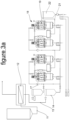
- the filtering device comprises a first receptacle which comprises at least one second filter unit with a filter bed and at least one third filter unit with a porous membrane, further comprising a second receptacle which comprises at least one second filter unit with a filter bed and at least one third filter unit with a porous membrane, wherein said first receptacle and said second receptacle are arranged in parallel or in series.
- This embodiment of the invention enables to perform the filtration process continuously.
- Such a system makes it possible to operate the filtering system of the first receptacle in a filtering mode, whereas in the meantime the filtering system of the second receptacle is in a cleaning mode.
- the filter bed in the first receptacle needs a regeneration or cleaning
- the filter bed in the second receptacle switches into the filtering mode
- the filter bed in the first receptacle switches into the cleaning mode.
- the configuration described above can alternatively be operated in a batch mode (discontinuously), if both receptacles are arranged in series.
- the liquid to be purified can first be passed through the second filter unit and the third filter unit of the first receptacle and thereafter be passed through the second filter unit and the third filter unit of the second receptacle, in order to achieve a still more efficient purification.
- a filtering material with a different composition in the filter bed of the second receptacle in order to eliminate other substances in said filter bed than in the filter bed of the first receptacle.
- the first receptacle could contain a filtering bed composed of graphene and a specific type of activated carbon that are particularly suitable to discolour wines or juices, while a subsequent receptacle could contain a filtering bed composed of zeolite and graphene-based material that are particularly suitable to remove alcohol.
- the receptacles could be substitutable, that is it could be possible to integrate in the system first a filtering system in order to recover aromas, sugars of other noble substances, whereas in a following phase the above mentioned receptacle (bell) could be substituted by another one in order to eliminate odors or to treat substances having a particularly reduced molecular dimension, or for whatever other envisaged purpose.
- the filtering device further comprises a cleaning system adapted to clean the filter bed of the second filter unit in the first receptacle in a cleaning modus while the filter bed of the second filter unit in the second receptacle is operating in a filter modus and vice versa to clean the filter bed of the second filter unit in the second receptacle in a cleaning modus while the filter bed of the second filter unit in the first receptacle is operating in a filter modus.
- the filter bed of the second filter unit comprises nanoplatelets, sheets or flakes of graphene, graphene oxide or graphite in combination with a spacing material in granular form selected from activated carbon and a zeolite compound.
- a spacing material in granular form selected from activated carbon and a zeolite compound.
- Subject-matter of the present invention further is a process for filtering a fluid, containing dissolved and optionally colloidal substances, and/or further impurities, by means of a filtering device wherein said fluid is a liquid which is filtered in a filtering device according to one of claims 1 to 5 and wherein the process comprises different phases, namely at least one filtering phase, wherein the liquid is passed through the second filter unit and consequently passed through the third filter unit and at least one regeneration phase, wherein particles detached from the filter bed of the second filter unit are recovered and recirculated to the second filter bed and/or at least one regeneration phase, wherein the membrane system of the third filter unit is regenerated by means of a cleaning liquid circulated through the third filter unit.
- the filtering device comprises a first receptacle which comprises at least one second filter unit with a filter bed and at least one third filter unit with a porous membrane
- the filtering device further comprises a second receptacle which comprises at least one second filter unit with a filter bed and at least one third filter unit with a porous membrane
- said first receptacle and said second receptacle are arranged in parallel or in series and wherein the filter bed of the second filter unit in the first receptacle is cleaned in a cleaning modus while the filter bed of the second filter unit in the second receptacle is operating in a filter modus and vice versa the filter bed of the second filter unit in the second receptacle is cleaned in a cleaning modus while the filter bed of the second filter unit in the first receptacle is operating in a filter modus.
- the liquid to be filtered and purified is one of the group comprising beverages, pharmaceutical products, chemical products, cosmetic products.
- Possible applications of the process of the present invention for instance in the food or pharmaceutical beverage industry concern the elimination of specific molecules in the permeate of selected products and make a rectified and clean product ready for further treatment. Examples include the gentle separation of all kind of sugars from the colloidal part and the pigments and the macromolecules, creating clear products containing mainly water, sugars, alcohols, acids and salts. All sugars from sucrose to glucose, fructose, mannitol, xylitol, including lactose, can be treated. Flavorings such as terpenes can be recovered by vacuum process and/or organic solvents.
- Organic acids such as malic acid can be recovered, for instance by solvent.
- Sugars can be filtered, caffeine can be removed, odors can be removed, colours in products such as sugars, wine, vinegars etc. can be removed, hemicellulosic hydrolysates (second generation sugars) can be purified.
- Further examples in the pharmaceutical field include the cleaning of permeates, obtaining selective fractions such as paracetamol Xantumol, or certain types of terpenes such as Humolene. Further recovery of polyphenolic substances (by solvent), purification of drugs as antipyretics, selection or purification of natural drug-like substances, removal of colour and purification of chemical-pharmaceutical products, e.g. treatment of antibiotics or removal of colour and purification of shellac glycerine or encapsulation of ions and molecules, with delayed release properties, treatment of skin problems, and synthesis of antibiotics.
- resveratrol in the cosmetics sector can be recovered or purified, plant or algae extracts can be recovered or glycolic, salicylic, retinoic acid etc. can be filtered or purified.
- the filtration process and device described herein may also be relevant for the filtration and separation in several other respects, for example in connection with acids, such as for instance glycolic, ferulic, ascorbic, tranexamic, kojic or azelaic acid, or with vitamins such as for instance vitamin A or vitamin C, or other substances as for example aloe vera, arbutin (currant) or dimethylethanolamine.
- acids such as for instance glycolic, ferulic, ascorbic, tranexamic, kojic or azelaic acid
- vitamins such as for instance vitamin A or vitamin C
- other substances as for example aloe vera, arbutin (currant) or dimethylethanolamine.
- the process according to the present invention can be used for decolourisation of beverages, for the extraction of aromatic substances or to remove odour, or to create water and alcohol-based drinks for the extraction of low molecular weight, for instance polyphenols, such as resveratrol.
- the process according to the present invention can be used for decolourisation of beverages, for the extraction of aromatic substances or to remove odour, or to create water and alcohol-based drinks for the extraction of low molecular weight, for instance polyphenols, such as resveratrol.
- polyphenols such as resveratrol
- distillates including all product resulting from alcohol distillation process (such as for instance acquavite d'uva, cachaça, cognac, gin, grappa, rum, sake, tequila, tapuy, vodka, whisky, etc.) fuselage oils can be removed, and where relevant, for example in the case of grappa, the distillate can be deodorized. Waste water can be treated and cleaned and certain pollutants can be removed.
- the process of the present invention makes it possible to obtain very clean permeates with a high selectivity of its components and an eluate containing all the aromatic parts and pigments. Furthermore in the wine sector the process can be used for tartaric stabilization or deacidification.
- the process, device and materials described in the present invention enable to reduce the content of 4 ethylphenol, 4 ethylgluaiacol and 3-methylbutanoic acid of microbial origin which represent an organoleptic defect and masks the original aromatic component of the wine.
- the invention disclosed in this document guarantees the ability to carry out a series of food processing activities, whether biological or not, without the adoption of chemical processes. Applying mechanical and physical filtration processes that, first of all, do not release micro or nano particles (and therefore do not involve any risk of contamination), the present invention is also compatible, for example, with the rules applicable to organic products, as set out in Regulations (EU) 2018/848, and 2020/464.
- EU Regulations
- this invention does not imply the use of transformation additives or process materials that are interdicted, excepting the use of solvents that are involved in the extraction phase, and safeguards the organoleptic characteristics of the product.
- the present invention therefore makes it possible to proceed with a series of activities of physical filtration and transformation of the matter, including the following:
- the process, device and materials described in the present invention are ideal to remove odour and unwanted substances, especially removing ochratoxin, octone and geosmin in the musts and beet juice.
- the regeneration process could be carried out via soda and a disinfection with OZONE (both in gas and watery form) or oxidizing detergents.
- the present invention may have further applications within the oenology, and more generally beverage, sector.
- graphene and other materials identified in this invention may be combined or blended within themselves and with polymers, such as Polyvinylpolypyrrolidone (PVPP) or Polyvinylpyrrolidone (PVP) for a number of purposes, including the following ones:
- PVPP Polyvinylpolypyrrolidone
- PVP Polyvinylpyrrolidone
- a PVPP based filter like the one described in the present invention may be used in various products and beverages, especially in the world of brewing.
- the PVPP acts on PNM, in particular on polyphenols responsible for astringency and turbidity (tanno-proteic compounds), thanks to their absorption.
- a PVPP based filter like the one described in the present invention may be used in various products and beverages, including wine and fruit juices.
- the PVPP based filter herewith described absorbs oxidized phenolic substances. It has a high and specific adsorption capacity of more oxidized phenolic substances: it is active on catechins, leucoanthocyanins and tannins, i.e. all substances that tend to be removed from wine by colloidal adsorption. Since PVPP is also characterized by the absolute chemical inertia, a filter based on PVPP, like the one described in this invention, is ideal in the treatment of fruit juices, musts and wines, in which it leaves no residues.
- the application of PVPP filters like the one described in this invention leads to a significant decrease in the ochre-yellow colour given by the oxidized polymers of phenolic substances, thus reducing the effect due to oxidation.
- the application of PVPP filters like the one described in this invention can lead to a slight decrease in red colour, comparable in any case to that caused by similar treatments with protein clarifiers.
- PVPP filter like the one described in this invention facilitates the elimination of the polyphenols responsible for the darkening of white wines, carries out an action on the must preserving the organoleptic qualities and eliminates bitter tastes.
- the process according to the present invention can be used for the treatment of soil from contaminants and water (including at radioactive sites) or decontamination from heavy metals and other hazardous materials.
- the filtering and purifying process serves to at least one purpose selected of: recovery of flavorings, in particular terpenes, recovery of organic acids, in particular malic acid, filtration of sugars, purification of hemicellulosic hydrolysates, recovery of polyphenolic substances, purification of drugs as antipyretics, selection or purification of natural drug-like substances, recovery or purification of resveratrol, recovery of plant or algae extracts, filtration or purification of glycolic, salicylic or retinoic acid.
- the filter material according to the present application can be used as adsorbing agent, but also as catalyst and separator.
- the process according to the present invention can for instance be utilized in hemodialysis, anesthesiology and hemoperfusion or for the removal of impurities, in desorption processes, light-tight feeding chambers or hemoperfusion cartridges.
- filter bed material alternatively also could be used gold, platinum or silver.
- the filter bed may also be composed of materials consisting of a single layer of atoms, known as two-dimensional materials.
- materials consisting of a single layer of atoms, known as two-dimensional materials. Examples are the graphene or modified graphene, but also one or more selected from the group comprising borophene, silicone, phosphorene, hexagonal boron nitride or white graphite, germanene and stanene.
- All of the above mentioned raw materials for the filter bed should be regarded either in isolation or as a compound in combination between each other, especially, but not only, in combination with granular activated carbon and /or graphene, or chemical carbon or chemically activated vegetable and/or vegetable carbon of organic-origin activated either chemically or via steam, including combinations thereof.
- the filtering device of the present invention can find a series of application, including for example the following ones: Detoxification of aqueous substances by filtration such as beer, wine, cider or other beverages (by distillation). Recovery of organic alcohols/extraction of ethanol from aqueous substances for the dealcoholization of wines, for instance by use of reverse osmosis process and/or by vacuum process. Purification or drying of ethanol, recovery of aromatic substances for pharmaceutical or cosmetic use (by specific enzymes of natural solvents) or recovery of substances with much smaller molecules, such as water.
- the process and devices disclosed in this document may also find additional applications within the pharmaceutical and healthcare sectors, such as for instance the identification and removal of bacteria from a liquid substance that is subject to the filtration procedure.
- the system may be able to detect and, then separate, even extremely small materials. This may also be the case for viruses, including but not limited to the Covid family (hence also the Covid-19) and the SARS.
- a filtration system may be foreseen as part of a drinkable water purification filter device, for particular use in connection with sanitized environments, but also outside and beyond them, for instance in residential or personal use contexts.
- the dissolved or optionally colloidal substance to be removed is one of the group comprising caffeine, odor substances, coloring substances.
- the process is carried out with a filtering device comprising the features as it has been described above.
- the filtering device and the filtering process of the present invention provide further possible applications.
- the various elements of the filter device can act in combination with each other and allow the progressive recovery of noble molecules, and also an improved regeneration of the filtering system, as explained below: After finishing the filtration process, valuable aromas can be recovered by the vacuum system.
- the filter bed can be heated to a suitable temperature and then operating under vacuum in order to evaporate substances or aromative molecules of interest that shall be extracted or reused.
- the process may continue by detaching form the filter bed the strongest molecules of organic acids with a suitable solvent, for instance ethyl alcohol.
- a suitable solvent for instance ethyl alcohol.
- This process makes it possible to clean the adsorbent material of the filter bed from acidic substances, which in turn makes the subsequent basic cleaning phase more effective.
- the process may continue with the start of a basic detergent (with lye) which allows the removal of organic colouring molecules.
- the filter bed of the second filter unit is washed and then regenerated, on site (with the clean in place (CIP) device) without the need to remove and/or replace the filter.
- CIP clean in place
- further regeneration for graphene
- reactivation for activated carbon
- the modular and extractable filter bed can then be regenerated repeatedly, and obviously can also be replaced by a new filter system. Replacement may be desirable where the use of alternative material such as zeolite for instance or a special type of carbon is required.
- the rotatable mixing device is moveable within the receptacle in an axial direction relative to the upper zone of the filter bed.
- the mixer with the plate is outside of the filtration bed once the filtration phase is ongoing. In that phase, there will be liquid between the plate and the filtration bed.
- the mixer moves down to have the plate and the knives close or even inside the filtration bed, (i) prior to starting the filtration phase in order to reshape the filtration bed, or also (after the conclusion of the filtration phase), (ii) during the phase of the emptying the bell (when air will be pumped into the bell to push the liquid out of the filtration bed and out of the bell and also out of the third filtration stage).
- the air pumped into the bell from the top, pushing down towards the filtration bed will push the liquid down.
- the air may enter laterally into the filtration bed and it may create, or increase the size of holes inside the filtration bed, which in turn may (counter-intuitively) result in the upper part of the filtration bed going up (this is because the air filtering inside the lateral part of the filtration bed, along the walls of the bell, or inside filtration bed holes/pathways, will reach air bubbles that formed within the filtration bed, and ultimately the air will crack the filtration bed, hence pushing the upper part of the filtration bed up).
- the mixer with plate could stay in the downward position, i.e. it will operate as a safety catch, preventing the upper part of the filtration bed to go all the way up to the top of the bell.
- the plate may still be detached from the filtration bed (with or without knives/whisks/helicoidally shaped dustpan inside the filtration bed). This is because the rotation of the plate causes an air/liquid flux or turbulence that can stir the filtration bed even without being inside it.
- the plate operating as a safety catch is the same concept that was explained in connection with the filtration bed, during the aspiration phase, when it is intended to recoup, for instance, the aromas. Also in that case since the filtration bed is free above, and is still wet hence it is a single compacted monolithic block, then the depression sucks the aromas (and cannot suck/detach the particles of graphene/activated carbon as they are all compacted forming the monolithic filtration bed), but ultimately this depression sucks up also the filtration bed as a dingle block, although the filtration bed only goes up to the level where the mixer plate (safety catch) is located.
- the filtration bed could be regarded as a sponge
- the mixer plate to be regarded as a metal cable, that stops the ascension of the filtration bed/sponge. So, also for the phase of (aroma/volatile noble substances) aspiration, the mixer plate preferably would stay in the downward position (as said to operate as a safety catch).
- the process comprises at least one filtering phase, wherein the fluid is passed through the second filter unit and consequently passed through the third filter unit, and at least one regeneration phase, wherein particles detached from the filter bed of the second filter unit are recovered and recirculated to the second filter bed, and/or at least one regeneration phase, wherein the membrane system of the third filter unit is regenerated by means of a cleaning liquid circulated through the third filter unit.
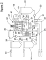
- FIG. 1 of the drawings represents a schematic view of a first embodiment of the present invention.
- the filtering device comprises a first storage container 10 containing the initial liquid product to be purified. From the bottom of this storage container the initial product is passed via line 11 to a first filter unit 12, wherein a membrane filtration takes place, wherein certain substances having a molecular weight above a defined limit value are removed and the liquid is discoloured to a certain degree.
- the permeate of this first filtration step is passed through line 13 to a product collection tank 14 and thereafter it is passed via line 15 and open valve 16 by means of pump 17 to a receptacle 18 which receives the second filter unit 19.
- the second filter unit 19 is a kind of a filter bed and, depending on the actual product to be processed, for example, it comprises a specific combined filter material of graphene and activated carbon.
- This filter material at least in part comes as granules.
- the graphene moiety may comprise graphene-based porous monolithic elements with a percolating macroporous network and accessible meso and micropores as disclosed in WO 2018/078427 A1 , the disclosure of which is incorporated herein by reference.
- the filter material may further comprise activated carbon in granular form as a spacing material.
- the liquid to be purified flows through a third filter unit 20 which can be disposed in a lower part of the same receptacle 18 which also houses the second filter unit 19, such that the third filter unit 20 is disposed downstream of the second filter unit.
- Said third filter unit comprises at least one porous membrane which for example may be of metal and which is passed by the liquid in a crossflow manner.
- Said third filter unit primarily serves to eliminate micro-particles which are released from the adsorbent material of the second filter unit by disintegration of said filter material over time.
- the purified liquid flows through line 21 into a product collection tank 22 and from there the treated product may be pumped by means of pump 23 and flow via line 24 to leave the filtration system via output line 25.
- the filtration device comprises a solvent storage tank 26 and a line 27 leading from the bottom region of said solvent storage tank 26 via valve 28 into line 29, wherein pump 17 is disposed which is adapted to pass solvent into the receptacle 18 of the second filter unit, if valve 28 is open. If valve 28 is closed, however, and valve 16 is open, product to be treated from product collection tank 14 can alternatively flow via line 15 and line 29 and can be pumped by means of pump 29 into the receptacle 18 of the second filter unit.
- a clean in place (CIP) device 30 is provided which makes it possible to pass a cleaning liquid into the receptacle 18 in order to clean the second filter unit 19.
- Said CIP device can be adapted to carry out an automatic cleaning operation, for instance at predetermined moments or after predetermined time intervals.
- an ultrasonic cleaning system 34 is provided for the cleaning of the third filter unit 20.
- solvent from the solvent storage tank 26 and lines 27 and 29 is passed into the filtration system and the system is not in the filtration mode it is possible to recover said solvent by means of pump 23 via open valve 31 into a separate solvent line 32 and either to discharge said solvent or to recover and circulate said solvent back via entry line 33 into solvent storage tank 26.
- the receptacle 18 is encased with a kind of cooling or heating jacket 35 with an input line 36 for a cooling or heating medium and a respective output line 37 for said medium, such that the liquid to be purified and the filter bed can be maintained on a predetermined temperature.
- the liquid flows into the bottom region of the receptacle and flows into the housing 38 of the third filter unit 20, which may be smaller and thus have a smaller cross section than the upper part of the receptacle 18.
- the housing 38 of the third filter unit may be directly attached to the bottom of the receptacle 18, wherein inside the housing a disc with holes for the passage of the liquid may be horizontally arranged in order to separate the interior of the second filter unit to the third filter unit.
- the retentate of the third filter unit can be recirculated and pass the second filter unit and the third filter unit several times and thereby becomes more and more concentrated.
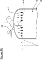
- FIG. 4 a shows an upper part of the interior of the receptacle 18 which houses the filter bed of the second filter unit. Above the filter bed 19 a disc-like plate 43 is disposed with slots. The upper end of the receptacle is connected to a vacuum line 44 and is equipped with a vacuum meter 45. By said vacuum line 44 it is possible to withdraw aroma or alcohol from the filter bed by depression. In this case vapours of said substances can pass through slots or holes in the plate 43.
- the mixing device 41 which includes the plate 43 can be rotated about its vertical axis during this operation as it is shown by the arrow in figure 4 a.
- a uniform pressure P is generated in a horizontal line in the upper part, 43.
- an internal speed and a pressure drop is generated by modifying the surface pressure and increasing the packing of the filtering bed, forcing more and more the product to pass and touch more granules of the bed, making the filtration efficient and homogeneous, closing also the possible preferential pathways.
- the pressure inside the filtering bed can also be managed with the pressure drop of the third stage trap-filter membrane or with the closing of valves at the filter outlet. This causes the product to act with important relative pressure against the granules of the filter bed, and depending on the material adopted, e.g.
- the liquid can enter more quickly and safely even into the smallest pores deep inside the granules. If the flow generates pressure, vacuum generates depression. Therefore the pressures are reversed and favour the exit of the volatile parts. Thanks to this approach there is no formation of permanent vacant air pockets that would otherwise form inside the fixed filtering bed, generating bubbles, preferential paths and breaks in the filtering state.
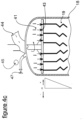
- Figure 4 b shows a different mode of operation where in the interior space of the receptacle 18 in the upper region above the disc-like plate 43 a pressure is created which is higher than the pressure in the filter bed 19, which is the case during the filtering mode of operation of the device.
- product to be purified is passed by entry line 29 into the space above the plate 43 such that a fluid level 46 of liquid is created above the plate 43 and filter bed 19. Said fluid then passes through the slots or holes in the plate 43 and flows into the filter bed 19, forced by the pressure created above the plate.
- the inlet line 29 can be shut by a valve 47 (see figure 4 a) in the operation mode according to figure 4 a , if aroma is to be withdrawn from the receptacle.
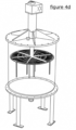
- Figure 4c shows an upper part of the interior of the receptacle 18 that houses the filter bed of the second filter unit.
- a disc-like plate 43 Above the filter bed 19 there is a disc-like plate 43.
- This plate is similar to a disc with a similar gatekeeper and/or deep knives at the bottom with variable height depending on the absorbent material used and the application to facilitate the escape of vapours or volatile substances. It is used in case of extraction of absorbent material from the bell 18 through a manhole cover or similar.
- the upper end of the receptacle is connected to a vacuum line 44 and is equipped with a vacuum meter 45. By said vacuum line 44 it is possible to withdraw aroma or alcohol from the filter bed by depression. In this case vapours of said substances can pass through slots or holes in the plate 43.
- the mixing device 41 which includes the plate 43, can be rotated about its vertical axis during this operation as it is shown by the arrow in figure 4c .
- the deep knife rotating and shaking system can rotate 90°, 180° or 360°, and it can rotate in various ways, e.g. in stretches, or in forward/backwards mode. As elaborated above, this approach may be deployed especially for systems requiring the vacuum process to be more effective, but also to facilitate the discharge of wet material in case of regeneration in a very high temperature furnace.
- the number 43 represents a perforated rotating plate or a 'wedge-shaped wire' filter system located at the top of the bell just before (i.e. upstream) the second filter stage (consisting of the graphene bed and activated carbon granules).
- the purpose of the plate 43 or wedge wire is not to filter but to shake and therefore change the position of the flakes and granules of composite material that makes up the filter bed (ultimately to solve the problem of preferential routes), to hold the filter bed downstream, and also to deflect the flow of product to be treated.
- the level of the filter bed may reach up to the plate 43 or the whisk or stirrer, or it may even exceed that level, and lie above the plate, or it may lie below it.
- the level depends on the filter media and the product to be filtered. In any case, the objective is to leave a higher volume that allows the uniform distribution of the product that makes up the filter bed. Therefore, the plate is either above or inside the filter bed, depending on the requirements.
- the room above the filtering bed is to be considered open upwards, i.e. the filtering system of the second stage, with graphene bed and activated carbon granules, are free upwards.
- the liquid to be filtered must enter the area 19 of the receptacle 18 under the plate 43, i.e. the filtering bed, and to do this, holes are provided in case a plate is adopted for the device.
- the perforated plate 43 or sheet may cover a smaller area than the inner surface section of the receptacle. Therefore the flow of product to be filtered could pass through the plate 43 or sheet metal (thanks to the holes), but also outside and on the sides of the plate 43.
- the pierced plate (as shown by the number 43 in Figure 4C ) works like a mixing device, since knives start from the plate, which are used to shake, create turbulence, and reposition and recompact the graphene flakes and activated carbon granules.
- the whisk especially when fitted with a top plate, also acts as a deflector or diffuser for the flow of liquid to be filtered.
- the perforated plate 43 located upstream of the filtering bed besides having the function of shaking and stirring the filtering bed, also has the function of acting as a deflector to break the flow of the product to be filtered, which then, falling on the plate, disperses on the filtering bed in a more uniform way (since in case there is only one concentrated flow that arrives directly on the filtering bed, this flow would dig a groove on the filtering bed, reducing the effectiveness of the filtration).
- the liquid to be filtered is inserted into the receptacle through one or more funnel-shaped inlet channels (moreover, the receptacle may have a convex bottom).
- the plate 43 may also have another function that is to hold the filter bed, while not fixing it and allowing the continuous modification of the position of the graphene flakes and carbon granules.
- the wet filter bed becomes compact, and therefore when vacuum and depression are used to extract aromas, the filter bed is sucked upwards.
- the plate 43 is also used to keep the filter bed in its original position or to limit its movement within the receptacle 18. If the plate 43 is outside the filter bed, the latter will not be able to move upwards.
- the filter bed in particular there is in fact a micro-perforated net and/or filter/wedge wire or membrane support.
- This net or membrane support is positioned between the 2 nd and the 3 rd filtering stage, in the lower part of the receptacle. It may have holes for instance ranging in size from 250 microns to 5 nanometres. Below it, instead, is expected, as 3 rd stage, the trap filter (which also works as a cross-filter) and could have holes of variable size between for example 0.2 microns and 0.5 nanometers.
- the present invention instead provides a diametrically opposed solution, i.e. it opts to leave the material free in the upper part and block it only in the lower part, this to facilitate the entry of the product into the filter bed, and to keep the upper part level.
- the granules that make up the filter bed are not stable and with disintegration generate voids.
- voids are filled thanks to the mixing device in the upper region of the receptacle 18 (for instance a whisk-like mixing device) which, by mixing and creating a pressure, allows the uniform dispersion and compactness of the substances that make up the filtering bed on the surface but also in the lower layers, where the substances that make up the filtering bed are pushed between one emptying and the other of the receptacle. Therefore, given the difficulty of blocking the material composing the filtering bed, the present invention takes the opposite approach to contemporary and prevailing technologies, leaving the material composing the filtering bed voluntarily free to position itself and compact itself progressively in a dynamic way. This approach allows the filter system to be used with any absorbent compound, since the system adapts to the characteristics of the material selected to compose the filter bed.
- the mixing device in the upper region of the receptacle 18 for instance a whisk-like mixing device
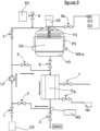
- figure 4 d shows in a schematic perspective view a part of the filtering device, namely the receptacle 18, which comprises the second filter unit and the mixing device, in a slightly altered embodiment of the present invention.
- a circular disc-like plate 43 which is disposed within the receptacle 18 and which forms part of the mixing device 41.
- the disc-like plate 43 is mounted on the lower end of a rotatable stem 56, which itself is axially moveable up and down within the cylindrical receptacle 18.
- This axial movement is performed by means of either a piston within a hydraulic cylinder, a threaded spindle or an elevating screw within a housing 57 serving as driving device, which is mounted in the upper region of the receptacle or above the receptacle 18.
- knives 58 protrude and extend into the filter material of the filter bed, which is not shown in figure 4 d , at least, when the disc-like plate 43 is in an axially lower position.
- the disc-like plate 43 of the mixing device 41 serves to compress the granular filter material of the filter bed, when the disc-like plate is axially moved downward and it serves as well as a device to pressurize the liquid to be filtered through the filter bed.
- the receptacle 18 may comprise a ground plate 59 in its lower end region as well as a cover plate 60 in its top region, on which the housing 57 of the driving device is arranged.
- the cover plate 60 can be removable in order to open the receptacle, for instance for reasons of revision or exchange of the filter material. Pipes, conducts, connections and valves to convey the liquid into the receptacle and out of the receptacle 18 are not shown in figure 4 d for reasons of clarity.
- figure 2a discloses an alternative embodiment of the present invention, wherein two receptacles 18 of the kind described in figure 2 above have been connected in series.
- Each of these receptacles comprise a second filter unit 19 and a third filter unit 53, respectively.
- the filtering device comprises a first storage container 10 containing the initial liquid product to be purified. From the bottom of this storage container 10 the initial product is passed via line 11 to a first filter unit 12, wherein a membrane filtration takes place, wherein certain substances having a molecular weight above a defined limit value are removed and the liquid is discoloured to a certain degree.
- the permeate of this first filtration step is passed through line 13 to a product collection tank 14 and thereafter it is passed via line 15 and open valve 16 by means of pump 17 and via open valve 50 to a first receptacle 18 which receives the second filter unit 19.
- the second filter unit 19 can for instance comprise a similar filter bed as described in the embodiment of figure 1 .
- the filtering device comprises a second receptacle 51 which may contain another second filter unit 19 with a similar filter bed as the first receptacle 18 contains.
- the purpose of this arrangement is to operate both second filter units alternatively, which means a filtering operation can take place within the second receptacle 51 while the first receptacle 18 is operated in a cleaning mode.
- This has the advantage that the filtering process can proceed continuously without any need of interruption.
- valve 50 is closed the permeate of the first filter unit 12 can be passed through open valve 52 into the second receptacle 51 and passed through the second filter bed 19 disposed therein.
- a membrane filtering step in cross-flow can follow in a third filter unit 53 comprised within the second receptacle 51 and thereafter the permeate of the third filter unit 53 can either be recycled to the entry line of the second receptacle or it is passed via open valve 54 and line 55 to product collection tank 22 from which it may leave the filtering device by output line 25.
- the filtering process within the second receptacle 51 thus can be carried several times by passing the permeate of the third filter unit 53 within the second receptacle back to the entry line of this receptacle, which means the liquid to be purified is recirculated and passed through the same filtering device several times as described above.
- both receptacles may be operated in parallel, providing a continuous filtering process, wherein a cleaning process is involved in one of the two similar receptacles during the filtering mode of the other receptacle.
- This variation can for instance have the advantage that different filter materials can be used within the filter beds of the two second filter units and/or different cross-flow membranes can be used in the two receptacles 18 and 51, in order to further improve the whole filtering process. In this case it would particularly be possible to remove different molecules from the liquid to be purified in each of the two receptacles 18 and 51.
- figure 3a an embodiment according to a further alternative of the present invention is described.
- two similar units of filtering devices which each have two receptacles 18 arranged similar to the embodiment of figure 3 described above, wherein both units are arranged in series.
- the filtering devices can be operated alternatively, one being in a filtering mode whereas the other is in a cleaning mode.
- figure 5 showing a schematic representation of a filtration system according to the present invention.
- FIG 5 we explain an exemplary operating mode of a filtering device according an embodiment of the present invention.
- the product to be treated enters through the inlet O3, which by opening the valve 1 is pumped by the pump L3 that goes up to the interception valve 4 to enter the receptacle which houses the filter bed G3 of the second filter unit (also see filter unit 19 above).
- the upper part being full of air is vented through the valve 9 a, during and until it is completely filled.
- the mixer or surface agitation system is activated and, with its action, it repositions and reshapes the filtration media contained located in G3.
- the mixer or self-levelling system can rotate and or descend for short distances in order to facilitate the uniform distribution of the filtration media throughout the surface of the filtering bed.
- the mixer or self-levelling tool can go up and down using the A3 screw motor or a piston system.
- Filtration continues by feeding the third stage through the valve 6, and in turn forcing the liquid to enter down the i3 stage (see also third filter unit 20 above), while valve 5 is closed. Stage i3 forces any particles of material that detach from G3, and are not caught by the H3 filtering net, to remain in the dirty part and to precipitate downwards between the closed valves 2 and 3. At this point, the purified, clear, product crosses the trap-filter and goes out through valve 8.
- the filtering bed may be heated or refrigerated by means of steam or refrigerant liquid passing through the P3 cavities. If, on the other hand, it is necessary to shake or compact the filtering materials of the filter bed (e.g. carbon, graphene, zeolites, polymers, compounds, metals. alloys, fiber, glass, etc. etc.), then the M3 ultrasonic or pneumatic vibrating system is activated.
- the filtering materials of the filter bed e.g. carbon, graphene, zeolites, polymers, compounds, metals. alloys, fiber, glass, etc. etc.
- the product is pushed out of the receptacle by inserting gas from the inlet O3 or by a dedicated valve inserted in the pipe between the pump L3 and valve 1.
- the gas runs along the same path as the liquid during filtration.
- the gas pushes the filtered product out of the bell (see also receptacle 18 above).
- the mixer or self-levelling system will support the upper part of the G3 filtration bed, which in turn favors the expulsion of liquid and gas.
- the system is regenerated thanks to the cip system.
- both of filtration and regeneration or washing or counter-washing of the I3 stage (with cross-flow), it is possible to recover the particulate or fine dust that detach from the G3 filtration bed thanks to a recirculation and recycling process that takes place through the outlined sequence.
- Valve 1 is closed (and equally valves 7 and 8 are closed but for the flushing phase), while valve 2 is opened.
- the product exiting from I3 passes through the L3 pump which - thanks to the operation of the ultrasonic or pneumatic vibration system - puts the particles back into suspension.
- the particles are then dragged by the flow through valve 4 and they therefore return to the upper part of the receptacle.
- the recouped matter is therefore recycled so as to reform and reintegrate the filtration bed.
- stage I3 can be regenerated thanks to the crossflow system, which operates (i) by opening valves 2, 5 and 8, while closing valves 4, 6, 3 and 7, and (ii) by having water or other liquid coming from a recirculation system (where the liquid enters through O3 and valve 1, and it recirculates on itself, passing through stage I3, thanks to the L3 pump).
- valve 3 When the time wash/cleaning phase is completed, all dirty water/liquid is discharged through valve 3, possibly also using a backwash system that injects water at specific pressure, operated by an external pump through valve 7, which is opened, while keeping closed valves 2, 5, 6 and 8 (hence enabling the flow to be discharged still through valve 3, which is open).
- a backwash system that injects water at specific pressure, operated by an external pump through valve 7, which is opened, while keeping closed valves 2, 5, 6 and 8 (hence enabling the flow to be discharged still through valve 3, which is open).
- Example 1 apple juice filtration through a filter device with a filter bed comprising graphene and activated vegetable carbon
- apple juice was filtered through a first filter unit according to the present invention comprising a microfiltration through a suitable membrane. After this first filtering step a clear and colloid-free liquid was received. The permeate of this first filter unit was thereafter passed through a decolouration device, after which a liquid product with a yellowish colour was obtained.
- specific enzymes or natural solvents may also be used to recover further noble polyphenolic molecules such as flavonoids known as procyanidins, proanthocyanidins, leucoanthocynidins, piconogenols, tannins, etc.
- Example 2 separation of sugars in a raw sugar solution from colloidal parts, pigments and macromolecules
- Example 3 Different filter materials for the filter bed of the second filter unit
- the second filter unit has the ability to retain all small polyphenol molecules such as anthocyanins procyanadins and polyphenols. It is possible to system with alcohol (ethanol) or another organic solvent such as glycerol or a solution diluted with alcohol glycerol and water. The process allows to recover aromatic or polyphenolic substances in a non-invasive way.
- Type Application Process description Effect Preferred Cut-off Process in the filter bed of the second filter unit brettanomyces purification on process or wash water or final product In connection with an aqueous solution derived from food production or with a washing liquid, filtration enables to retain substances such as brett. In the oenological sector, not only the washing water, but also the product itself can be purified, once filtered the permeate no longer contains brett.
- the bleached food solution or liquid may be treated in order to reduce the fraction of acid compounds present.
- An additional advantage of the process of the present invention is its environmental friendliness. For instance it is to emphasize that the invention does not use ionic and cationic exchangers. The invention does not use toxic chemicals, and thus it can be used for organic production. There is no need to solve the problem of disposal of particles, as the invention uses the trap filter of the third filter unit. The invention does not operate in the traditional way in which carbon was used, and once exhausted it had to be disposed. The invention is greener and more sustainable, as it uses regeneration, for example, simply via 'soda' as opposed to aggressive acids.
- Activated carbon currently used in the food sector is sold in powder form or in granules, depending on the application.
- Powder is a very fine powder that has little or no filtering capacity (as it does not form a cake, through which the liquid is supposed to pass in order to be filtered out). Once used, the powder is thrown away.
- Granulate filters do have a filtering capacity, which is why they are used as safety filters. When used for certain applications, such as in water or similar liquids, once they have been used up they can be regenerated (typically, via an external oven, not in place). Granulate filter have a low pressure drop, which means that they do not perform as well as they are not as porous as powder filters.
- Granules are used in a similar way to resins. Instead, powder is added to large masses of liquid, 150, 500, 1000 hectolitres, for instance, in percentages of 1-3% up to 150 gr/hl. Powder is decanted together with other technological aids, such as bentonite or others, and it is added and left to decant precisely because it cannot be as effective as granular filters. Since decantation is not enough, the process requires a second step, usually microfiltration or centrifugation to remove the micro particles visible in suspension.
- Coal powder can also be combined with diatomaceous earth or cellulose, fossil flour, generally identified as filter aids, increasing the degree of filtration, where both the carbon and the flour are dosed in line during filtration.
- Activated carbon is chemically or steam-activated, giving it a specific porous morphology which, depending on its activation, lends itself to retaining different types of molecules such as color, (brett) odors, contaminants or poisons.
- the compound that the present invention uses as a filtration bed for certain preferred embodiments may include, for instance, graphene combined with granular activated carbons (which is not a resin-based compound).
- This compound lends itself to being filtered and regenerated, hence without having the problem of the disposal.
- the system based on the said compound is clean in the sense that particles of graphene or carbon are removed from the permeate due to the operation of a trap filter that safely closes the filtration system. So, this approach is safer, greener and more efficient than traditional use of powder or granular carbon, as explained above.
- the receptacle (bell) of the second filter unit is combined with the roughing stage of the first filter unit, and the trap filter of the third filter unit to remove any micro-particles, where the porosity of the trap filter depends on the substances to be filtered, and typically ranges from 0,5 micron to 0,5 kd.
- the filter process within the third filter unit does not involve a reverse osmosis (as in the prior art document WO 2015/034776 A1 , where the reverse osmosis has the aim of concentrating the sugars), instead it involves a safety procedure to remove microparticle that may be detached from the filtration bed.
- the said prior art document points to ionic and cationic exchange resins (sieve) and related housing, hence a system that is similar to the one used for rectified juices and sweeteners that go through a carbon, bentonite based filter for removal of proteins, odors, color and salt via resins and subsequent concentration starting with the reverse osmosis.
Landscapes
- Chemical & Material Sciences (AREA)
- Chemical Kinetics & Catalysis (AREA)
- Engineering & Computer Science (AREA)
- Water Supply & Treatment (AREA)
- Health & Medical Sciences (AREA)
- Organic Chemistry (AREA)
- Food Science & Technology (AREA)
- Life Sciences & Earth Sciences (AREA)
- General Engineering & Computer Science (AREA)
- Bioinformatics & Cheminformatics (AREA)
- Biochemistry (AREA)
- General Health & Medical Sciences (AREA)
- Genetics & Genomics (AREA)
- Toxicology (AREA)
- Wood Science & Technology (AREA)
- Zoology (AREA)
- Nutrition Science (AREA)
- Polymers & Plastics (AREA)
- Separation Using Semi-Permeable Membranes (AREA)
- Water Treatment By Sorption (AREA)
Claims (11)
- Filterungsvorrichtung zum Filtern eines Fluids, die umfasst:(i) mindestens eine erste Filtereinheit (12), die dazu dient, in einer ersten Filterstufe Stoffe mittels einer Membranfiltration zu entfernen, die eine Mikrofiltrations- und/oder eine Ultrafiltrations- und/oder eine Nanofiltrationsmembran umfasst, wobei die entfernten Stoffe ein Molekulargewicht oberhalb eines definierten Grenzwertes besitzen, was zu einem Permeat der ersten Filtereinheit führt, das hauptsächlich Moleküle mit niedrigem Molekulargewicht enthält,(ii) eine zweite Filtereinheit (19), die stromabwärts der ersten Filtereinheit (12) angeordnet ist, zur Behandlung des Permeats der ersten Filtereinheit,wobei die Filterungsvorrichtung eine Mischvorrichtung (41) innerhalb eines Behälters (18) umfasst, der die zweite Filtereinheit (19) enthält,wobei die zweite Filtereinheit (19) ein Filterbett umfasst, das ein Partikelfiltermaterial umfasst, das insbesondere mindestens ein Filtermaterial aus der Gruppe umfasst, die Graphen und Aktivkohle umfasst.Bilden eines Filterbettes, das sich aus verdichteten Partikeln in Form von Graphenflocken und Aktivkohlegranulat zusammensetzt,
und(iii) eine dritte Filtereinheit (20), die stromabwärts der zweiten Filtereinheit (19) angeordnet ist, zur Aufbereitung des Permeats der zweiten Filtereinheit, wobei die dritte Filtereinheit (20) eine porenhaltige Membran umfasst,wobei, im Hinblick auf die zweite Filtereinheit (19),oberhalb des Filterbettes zwischen dem Filterbett selbst und jeder weiteren Struktur, die einen Teil des Behälters bildet, ein Hohlraum vorhanden ist, der das Filterbett aufnimmt,wobei die Mischvorrichtung (41) um eine vertikale Achse drehbar und mit einem Motor (42) antriebsverbunden ist,und wobei die drehbare Mischvorrichtung (41)a. innerhalb des Behälters (18) in einer axialen Richtung relativ zu einer oberen Zone des Filterbettes beweglich ist,b. eine scheibenartige Platte (43) mit Löchern und Schlitzen für das Hindurchtreten des Fluids zu dem Filterbett umfasst,c. und Messer umfasst, die sich entlang der axialen Richtung von einer Unterseite der Platte (43) in das Filterbett hinein erstrecken,wobei- wenn der Filtrationsprozess in Betrieb ist,∘ sich die drehbare Mischvorrichtung (41) außerhalb des Filterbettes befindet, wobei sich Flüssigkeit zwischen der Platte und dem Filterbett befindet,∘ die scheibenartige Platte (43) dafür konfiguriert ist, durch axiale Bewegungen zusätzlichen Druck auf das Fluid auszuüben,der Behälter (18) feste Seitenwände und einen festen Boden hat, aber das Filtrationsbett darüber frei ist, so dass sich das Filterbett auf und ab bewegen kann, während die scheibenartige Platte (43) als Sicherheitsfangvorrichtung fungiert,
und wobei- die drehbare Mischvorrichtung (41) vor Beginn der Filtrationsphase∘ dafür konfiguriert ist, sich nach unten zu bewegen, um die scheibenartige Platte (43) nahe an das Filterbett und die Messer im Inneren des Filterbettes heranzuführen,∘ und dafür konfiguriert ist, sich zu drehen, um das Filterbett neu zu formen und dabei das Filterbett aufzubrechen, wenn es verdichtet ist,wobei die drehbare Mischvorrichtung (41) dafür ausgelegt ist, das Granulat nur in der oberen Region des Filterbettes zu mischen, wodurch bevorzugte Pfade im Filterbettmaterial beseitigt werden, die eine effiziente Filterwirkung beeinträchtigen würden. - Filterungsvorrichtung nach Anspruch 1, wobei die zweite Filtereinheit (19) innerhalb des Behälters (18) mindestens ein automatisches Reinigungssystem umfasst, das einen Einlass für eine Reinigungslösung umfasst, der an dem Behälter stromaufwärts des Filterbettes der zweiten Filtereinheit (19) angeordnet ist.
- Filterungsvorrichtung nach einem der Ansprüche 1 und 2, die ein Ultraschallsystem oder ein Vibrationssystem als eine Reinigungsvorrichtung umfasst, das der zweiten Filtereinheit (19) und/oder der dritten Filtereinheit (20) zugewiesen ist.
- Filterungsvorrichtung nach einem der Ansprüche 1 bis 3, wobei der Behälter (18), der die zweite Filtereinheit (19) enthält, mit einem Kühl- oder Heizsystem versehen ist, um das Filterbett auf einer vorgegebenen Temperatur oder innerhalb eines vorgegebenen Temperaturbereichs zu halten.
- Filterungsvorrichtung nach einem der vorangehenden Ansprüche, wobei das Filterbett der zweiten Filtereinheit (19) Nanoplättchen, -lagen oder -flocken aus Graphen, modifiziertem Graphen, Graphenoxid oder Graphit in Kombination mit einem Abstandshaltermaterial in Granulatform, das aus chemisch oder anderweitig aktivierter Kohle, Kieselgur, Zeolith, Silber, Silberchlorid, Bentonit, Eisenoxid und Phosphoren ausgewählt ist, umfasst, wobei bevorzugt, wenn die Filterungsvorrichtung in einem önologischen Sektor und allgemeiner in einem Getränkesektor angewendet wird, Graphen und die anderen Materialien in sich selbst und mit Polymeren wie zum Beispiel Polyvinylpolypyrrolidon (PVPP) oder Polyvinylpyrrolidon (PVP) kombiniert oder gemischt werden.
- Prozess zum Filtern eines Fluids, das gelöste und optional kolloidale Stoffe und/oder weitere Verunreinigungen enthält, mittels einer Filterungsvorrichtung,wobei das Fluid eine Flüssigkeit ist, die in einer Filterungsvorrichtung gefiltert wird,wobei eine Filterungsvorrichtung nach einem der Ansprüche 1 bis 5 verwendet wird, undwobei der Prozess verschiedene Phasen umfasst, und zwar:- mindestens eine Filterungsphase, wobei die Flüssigkeit durch die erste Filtereinheit (12), die zweite Filtereinheit (19) und anschließend durch die dritte Filtereinheit (20) geleitet wird,- und mindestens eine Regenerationsphase, wobei- Partikel, die sich von dem Filterbett (G3) der zweiten Filtereinheit (19) ablösen, aufgefangen und in das Filterbett der zweiten Filtereinheit (20) rezirkuliert werden,
und/oder- das Membransystem (I3) der dritten Filtereinheit (20) mittels einer Reinigungsflüssigkeit regeneriert wird, die durch die dritte Filtereinheit (20) zirkuliert wird,
und wobeidie drehbare Mischvorrichtung (41) verwendet wird, wenn das Filterbett verdichtet wird und verstopft, und es mischt, um das Gewicht zu verringern, die Kohäsion zwischen den Granulatkörnern zu beseitigen und dadurch den Druckabfall in dem Filterbett zu verringern, so dass das System gewaschen werden kann,wobei die drehbare Mischvorrichtung (41) das Granulat nur in der oberen Region des Filterbettes mischt, wodurch bevorzugte Pfade im Filterbettmaterial beseitigt werden, die eine effiziente Filterwirkung beeinträchtigen würden. - Prozess nach Anspruch 6, wobei die Filterungsvorrichtung des Weiteren ein zweites Gefäß (18) umfasst, das mindestens eine zweite Filtereinheit (19) mit einem Filterbett und mindestens eine dritte Filtereinheit (20) mit einer porenhaltigen Membran umfasst, wobei das erste Gefäß und das zweite Gefäß parallel oder in Reihe angeordnet sind und wobei das Filterbett der zweiten Filtereinheit in dem ersten Gefäß in einem Reinigungsmodus gereinigt wird, während das Filterbett der zweiten Filtereinheit in dem zweiten Gefäß in einem Filtermodus arbeitet, und umgekehrt das Filterbett der zweiten Filtereinheit in dem zweiten Gefäß in einem Reinigungsmodus gereinigt wird, während das Filterbett der zweiten Filtereinheit in dem ersten Gefäß in einem Filtermodus arbeitet.
- Prozess nach einem der Ansprüche 6 und 7, wobei in der Filterungsphase ein Druck erzeugt wird, um die Flüssigkeit mittels mindestens einer Druck erzeugenden Vorrichtung, die aus der Gruppe ausgewählt ist, die eine stromaufwärts der zweiten Filtereinheit (19) angeordnete Pumpe, die scheibenartige Platte (43) mit Löchern und/oder Schlitzen der Mischvorrichtung der zweiten Filtereinheit (19) und stromabwärts der zweiten Filtereinheit (19) angeordnete Ventile umfasst, durch die zweite Filtereinheit (19) zu drücken, wobei der Druck innerhalb der zweiten Filtereinheit (19) in der Filterungsphase höher ist als in einer Regenerationsphase oder in einer Reinigungsphase.
- Prozess nach einem der Ansprüche 6 bis 8, wobei die zu filternde und zu reinigende Flüssigkeit eine aus der Gruppe ist, die Getränke, pharmazeutische Produkte, chemische Produkte und kosmetische Produkte umfasst, wobei der Filterungs- und Reinigungsprozess bevorzugt mindestens einem von Folgendem dient: Rückgewinnung von Aromastoffen, insbesondere Terpenen, Rückgewinnung von organischen Säuren, insbesondere Apfelsäure, Filtration von Zuckern, Reinigung von Hemicellulosehydrolysaten, Rückgewinnung von polyphenolischen Stoffen, Reinigung von Arzneimitteln als Antipyretika, Selektion oder Reinigung von natürlichen arzneimittelähnlichen Stoffen, Rückgewinnung oder Reinigung von Resveratrol, Rückgewinnung von Pflanzen- oder Algenextrakten, Filtration oder Reinigung von Glykol-, Salicyl- oder Retinsäure.
- Prozess nach einem der Ansprüche 6 bis 9, wobei der zu entfernende gelöste oder optional kolloidale Stoff eines aus der Gruppe ist, die Koffein, Geruchsstoffe und Farbstoffe umfasst.
- Prozess nach einem der Ansprüche 6 bis 10, wobei Wertstoffe, die in mindestens einer der Filtereinheiten zurückgehalten werden, aus dem jeweiligen Retentat und/oder aus dem Filtermaterial der jeweiligen Filtereinheit zurückgewonnen werden.
Applications Claiming Priority (2)
| Application Number | Priority Date | Filing Date | Title |
|---|---|---|---|
| EP20176481.8A EP3915669A1 (de) | 2020-05-26 | 2020-05-26 | Filtervorrichtung zum filtern eines fluids und verfahren zum filtern eines fluids |
| PCT/EP2021/064118 WO2021239847A1 (en) | 2020-05-26 | 2021-05-26 | Filtering device for filtering a fluid and process for filtering a fluid |
Publications (3)
| Publication Number | Publication Date |
|---|---|
| EP4100150A1 EP4100150A1 (de) | 2022-12-14 |
| EP4100150C0 EP4100150C0 (de) | 2024-08-07 |
| EP4100150B1 true EP4100150B1 (de) | 2024-08-07 |
Family
ID=70857055
Family Applications (3)
| Application Number | Title | Priority Date | Filing Date |
|---|---|---|---|
| EP20176481.8A Withdrawn EP3915669A1 (de) | 2020-05-26 | 2020-05-26 | Filtervorrichtung zum filtern eines fluids und verfahren zum filtern eines fluids |
| EP21728562.6A Pending EP4157496A1 (de) | 2020-05-26 | 2021-05-26 | Verfahren zur behandlung eines fluids |
| EP21729287.9A Active EP4100150B1 (de) | 2020-05-26 | 2021-05-26 | Filtervorrichtung zum filtern eines fluids und verfahren zum filtern eines fluids |
Family Applications Before (2)
| Application Number | Title | Priority Date | Filing Date |
|---|---|---|---|
| EP20176481.8A Withdrawn EP3915669A1 (de) | 2020-05-26 | 2020-05-26 | Filtervorrichtung zum filtern eines fluids und verfahren zum filtern eines fluids |
| EP21728562.6A Pending EP4157496A1 (de) | 2020-05-26 | 2021-05-26 | Verfahren zur behandlung eines fluids |
Country Status (3)
| Country | Link |
|---|---|
| US (1) | US12390769B2 (de) |
| EP (3) | EP3915669A1 (de) |
| WO (2) | WO2021239847A1 (de) |
Families Citing this family (6)
| Publication number | Priority date | Publication date | Assignee | Title |
|---|---|---|---|---|
| TWI847692B (zh) * | 2023-05-12 | 2024-07-01 | 偉鵬科技有限公司 | 模組化全自動清洗系統設備 |
| CN116688635A (zh) * | 2023-06-14 | 2023-09-05 | 河北维尔利生物科技有限公司 | 一种中药提取液过滤的三级除沉工艺 |
| CN117448015B (zh) * | 2023-09-28 | 2024-10-18 | 江苏龙腾城矿环境技术有限公司 | 一种高温微负压条件下持续动态清理积碳装置及方法 |
| CN117791326B (zh) * | 2024-01-02 | 2024-06-07 | 徐州中铁电气有限公司 | 一种组合式光伏变电站 |
| CN118988066B (zh) * | 2024-10-23 | 2025-01-24 | 山西省交通新技术发展有限公司 | 一种隧道施工用注浆机 |
| CN120132668B (zh) * | 2025-05-15 | 2025-07-18 | 福建华夏合成革有限公司 | 一种石墨烯合成革制备用混合装置及使用方法 |
Family Cites Families (22)
| Publication number | Priority date | Publication date | Assignee | Title |
|---|---|---|---|---|
| FR2373319A1 (fr) * | 1976-12-09 | 1978-07-07 | Flipo Leon | Procede et dispositif de filtration |
| GB2072326B (en) * | 1980-03-11 | 1983-09-14 | Izumi Masahiko | Air conditioning apparatus |
| US4437866A (en) * | 1982-08-24 | 1984-03-20 | Harry Pweblo | Pollution harness |
| FR2628337B1 (fr) * | 1988-03-11 | 1992-02-07 | Lyonnaise Eaux | Installation pour la filtration et l'epuration de fluides notamment de liquides, tels que l'eau |
| BRPI0815054A2 (pt) * | 2007-08-07 | 2015-02-10 | Kurita Water Ind Ltd | Método e aparelho de speração de membrana. |
| WO2011026025A1 (en) | 2009-08-28 | 2011-03-03 | Bdnp Technologies, Llc | Devices and methods for removing contaminants and other elements, compounds, and species from fluids |
| US8361321B2 (en) | 2010-08-25 | 2013-01-29 | Lockheed Martin Corporation | Perforated graphene deionization or desalination |
| EP2619568A4 (de) * | 2010-09-23 | 2014-06-25 | Ge Healthcare Bio Sciences | Einweg-schlämmungs- und chromatographiesysteme |
| WO2013085099A1 (ko) * | 2011-12-09 | 2013-06-13 | 진우통상(주) | 액상오존수 발생기를 이용한 악취 정화장치 |
| WO2015034776A1 (en) * | 2013-09-06 | 2015-03-12 | Zenbury International Limited | System and method for production of clarified citrus juice concentrates containing 100% juice |
| PT2893817T (pt) * | 2014-01-10 | 2017-10-30 | Wia Wine Ag | Dispositivo e método para a produção de uma bebida desalcoolizada |
| WO2018078427A1 (en) | 2016-10-31 | 2018-05-03 | Nanosme Se | Graphene-based filtering element and uses thereof |
| US10213707B2 (en) * | 2016-12-09 | 2019-02-26 | Orochem Technologies, Inc. | Continuous process for purification of steviol glycosides from stevia leaves using simulated moving bed chromatography |
| SG10202110648SA (en) * | 2017-03-27 | 2021-11-29 | Agency Science Tech & Res | Method and system for converting carbon dioxide into solid carbonates |
| US10189762B1 (en) * | 2017-07-07 | 2019-01-29 | Orochem Technologies, Inc. | Process for purification and separation of cannabinoids, from dried hemp and cannabis leaves |
| CN109418680A (zh) * | 2017-08-22 | 2019-03-05 | 秭归县屈姑食品有限公司 | 一种用于果汁加工过程中的脱酸脱苦罐 |
| EP3717497B1 (de) * | 2017-11-28 | 2023-11-08 | Blue Tree Technologies Ltd. | Verfahren zur herstellung von zuckerarmen getränken |
| CN108079884A (zh) * | 2017-12-12 | 2018-05-29 | 浙江凯盈新材料有限公司 | 一种银浆的生产线 |
| CN108554274A (zh) * | 2018-01-06 | 2018-09-21 | 南昌叁润科技有限公司 | 一种建筑用石灰膏制作搅拌设备 |
| US10792618B2 (en) * | 2018-06-19 | 2020-10-06 | Sartorius Stedim Biotech Gmbh | Particle separation and/or purification of a fluid |
| WO2020030943A1 (en) * | 2018-08-04 | 2020-02-13 | Babaluo Ali Akbar | Gray water treatment system |
| BE1026801B1 (nl) * | 2018-11-22 | 2020-06-25 | Anheuser Busch Inbev Sa | Werkwijze voor het verkrijgen van een geconcentreerd geur- en smaakmengsel en gebruik ervan |
-
2020
- 2020-05-26 EP EP20176481.8A patent/EP3915669A1/de not_active Withdrawn
-
2021
- 2021-05-26 EP EP21728562.6A patent/EP4157496A1/de active Pending
- 2021-05-26 WO PCT/EP2021/064118 patent/WO2021239847A1/en not_active Ceased
- 2021-05-26 US US17/927,441 patent/US12390769B2/en active Active
- 2021-05-26 EP EP21729287.9A patent/EP4100150B1/de active Active
- 2021-05-26 WO PCT/EP2021/064097 patent/WO2021239837A1/en not_active Ceased
Also Published As
| Publication number | Publication date |
|---|---|
| EP4157496A1 (de) | 2023-04-05 |
| US12390769B2 (en) | 2025-08-19 |
| US20230294045A1 (en) | 2023-09-21 |
| WO2021239837A1 (en) | 2021-12-02 |
| EP4100150A1 (de) | 2022-12-14 |
| EP4100150C0 (de) | 2024-08-07 |
| WO2021239847A1 (en) | 2021-12-02 |
| EP3915669A1 (de) | 2021-12-01 |
Similar Documents
| Publication | Publication Date | Title |
|---|---|---|
| EP4100150B1 (de) | Filtervorrichtung zum filtern eines fluids und verfahren zum filtern eines fluids | |
| AU2007330742B2 (en) | Use of a primary liquid filtration/stabilization installation for triple purpose. | |
| US9422170B2 (en) | Method for producing potable water and/or purifying water including the elimination of a target compound and filtration within a filter drum | |
| US4647415A (en) | Method of producing a filter pad | |
| US20110266217A1 (en) | Method for cleaning filter separation systems | |
| TWI830845B (zh) | 淨水用過濾器及具備過濾器之淨水器 | |
| EP1806321A1 (de) | Adsorptionsmittel, herstellungsverfahren dafür und verfahren zur verarbeitung von ölhaltigem abwasser | |
| CN101306348A (zh) | 用于去除水的颜色、异味和胶体物的过滤介质及制备方法 | |
| US20150367267A1 (en) | Filtering methods for fluids and devices for carrying out said methods | |
| KR100892761B1 (ko) | 필터 및 이를 구비한 정화 장치 | |
| CN205838735U (zh) | 一种一体化污水处理器 | |
| CA2517770C (en) | Industrial silicon carbide filtration method | |
| JP3117979B2 (ja) | 糖液の精製方法 | |
| Pramanik | Biological pre-treatment to enhance low pressure membrane filtration for wastewater reclamation | |
| DE19652500B4 (de) | Anschwemmfilter und Verfahren zu seiner Reinigung | |
| US20250257298A1 (en) | Regenerative Filter System For Distilled Spirits | |
| RU2810056C1 (ru) | Комбинированный аппарат для очистки растительных масел | |
| CN119327274A (zh) | 一种黑茶活性成分超滤膜高效提取与纯化方法 | |
| JPH11347376A (ja) | 多孔質セラミックフィルタおよびこれを用いる流体浄化方法ならびに装置 | |
| JP3067121B2 (ja) | 浄水器 | |
| JPH0947654A (ja) | ポリフェノール吸着剤 | |
| US1667439A (en) | Apparatus for purifying and simultaneously sterilizing water or other liquids or gase | |
| CN201952307U (zh) | 新型污水处理器 | |
| Kurniasari | Application of Pre-coated Microfiltration Ceramic Membrane with Powdered Activated Carbon for Natural Organic Matter Removal from Secondary Wastewater Effluent | |
| JPH047662B2 (de) |
Legal Events
| Date | Code | Title | Description |
|---|---|---|---|
| STAA | Information on the status of an ep patent application or granted ep patent |
Free format text: STATUS: UNKNOWN |
|
| STAA | Information on the status of an ep patent application or granted ep patent |
Free format text: STATUS: THE INTERNATIONAL PUBLICATION HAS BEEN MADE |
|
| PUAI | Public reference made under article 153(3) epc to a published international application that has entered the european phase |
Free format text: ORIGINAL CODE: 0009012 |
|
| STAA | Information on the status of an ep patent application or granted ep patent |
Free format text: STATUS: REQUEST FOR EXAMINATION WAS MADE |
|
| 17P | Request for examination filed |
Effective date: 20220905 |
|
| AK | Designated contracting states |
Kind code of ref document: A1 Designated state(s): AL AT BE BG CH CY CZ DE DK EE ES FI FR GB GR HR HU IE IS IT LI LT LU LV MC MK MT NL NO PL PT RO RS SE SI SK SM TR |
|
| STAA | Information on the status of an ep patent application or granted ep patent |
Free format text: STATUS: EXAMINATION IS IN PROGRESS |
|
| 17Q | First examination report despatched |
Effective date: 20221214 |
|
| DAV | Request for validation of the european patent (deleted) | ||
| DAX | Request for extension of the european patent (deleted) | ||
| GRAP | Despatch of communication of intention to grant a patent |
Free format text: ORIGINAL CODE: EPIDOSNIGR1 |
|
| STAA | Information on the status of an ep patent application or granted ep patent |
Free format text: STATUS: GRANT OF PATENT IS INTENDED |
|
| INTG | Intention to grant announced |
Effective date: 20240226 |
|
| GRAS | Grant fee paid |
Free format text: ORIGINAL CODE: EPIDOSNIGR3 |
|
| GRAA | (expected) grant |
Free format text: ORIGINAL CODE: 0009210 |
|
| STAA | Information on the status of an ep patent application or granted ep patent |
Free format text: STATUS: THE PATENT HAS BEEN GRANTED |
|
| AK | Designated contracting states |
Kind code of ref document: B1 Designated state(s): AL AT BE BG CH CY CZ DE DK EE ES FI FR GB GR HR HU IE IS IT LI LT LU LV MC MK MT NL NO PL PT RO RS SE SI SK SM TR |
|
| REG | Reference to a national code |
Ref country code: GB Ref legal event code: FG4D |
|
| REG | Reference to a national code |
Ref country code: CH Ref legal event code: EP |
|
| REG | Reference to a national code |
Ref country code: IE Ref legal event code: FG4D |
|
| REG | Reference to a national code |
Ref country code: DE Ref legal event code: R096 Ref document number: 602021016849 Country of ref document: DE |
|
| U01 | Request for unitary effect filed |
Effective date: 20240909 |
|
| U07 | Unitary effect registered |
Designated state(s): AT BE BG DE DK EE FI FR IT LT LU LV MT NL PT RO SE SI Effective date: 20240924 |
|
| PG25 | Lapsed in a contracting state [announced via postgrant information from national office to epo] |
Ref country code: NO Free format text: LAPSE BECAUSE OF FAILURE TO SUBMIT A TRANSLATION OF THE DESCRIPTION OR TO PAY THE FEE WITHIN THE PRESCRIBED TIME-LIMIT Effective date: 20241107 |
|
| PG25 | Lapsed in a contracting state [announced via postgrant information from national office to epo] |
Ref country code: GR Free format text: LAPSE BECAUSE OF FAILURE TO SUBMIT A TRANSLATION OF THE DESCRIPTION OR TO PAY THE FEE WITHIN THE PRESCRIBED TIME-LIMIT Effective date: 20241108 Ref country code: PL Free format text: LAPSE BECAUSE OF FAILURE TO SUBMIT A TRANSLATION OF THE DESCRIPTION OR TO PAY THE FEE WITHIN THE PRESCRIBED TIME-LIMIT Effective date: 20240807 |
|
| PG25 | Lapsed in a contracting state [announced via postgrant information from national office to epo] |
Ref country code: IS Free format text: LAPSE BECAUSE OF FAILURE TO SUBMIT A TRANSLATION OF THE DESCRIPTION OR TO PAY THE FEE WITHIN THE PRESCRIBED TIME-LIMIT Effective date: 20241207 |
|
| PG25 | Lapsed in a contracting state [announced via postgrant information from national office to epo] |
Ref country code: HR Free format text: LAPSE BECAUSE OF FAILURE TO SUBMIT A TRANSLATION OF THE DESCRIPTION OR TO PAY THE FEE WITHIN THE PRESCRIBED TIME-LIMIT Effective date: 20240807 |
|
| PG25 | Lapsed in a contracting state [announced via postgrant information from national office to epo] |
Ref country code: ES Free format text: LAPSE BECAUSE OF FAILURE TO SUBMIT A TRANSLATION OF THE DESCRIPTION OR TO PAY THE FEE WITHIN THE PRESCRIBED TIME-LIMIT Effective date: 20240807 Ref country code: RS Free format text: LAPSE BECAUSE OF FAILURE TO SUBMIT A TRANSLATION OF THE DESCRIPTION OR TO PAY THE FEE WITHIN THE PRESCRIBED TIME-LIMIT Effective date: 20241107 |
|
| PG25 | Lapsed in a contracting state [announced via postgrant information from national office to epo] |
Ref country code: RS Free format text: LAPSE BECAUSE OF FAILURE TO SUBMIT A TRANSLATION OF THE DESCRIPTION OR TO PAY THE FEE WITHIN THE PRESCRIBED TIME-LIMIT Effective date: 20241107 Ref country code: PL Free format text: LAPSE BECAUSE OF FAILURE TO SUBMIT A TRANSLATION OF THE DESCRIPTION OR TO PAY THE FEE WITHIN THE PRESCRIBED TIME-LIMIT Effective date: 20240807 Ref country code: NO Free format text: LAPSE BECAUSE OF FAILURE TO SUBMIT A TRANSLATION OF THE DESCRIPTION OR TO PAY THE FEE WITHIN THE PRESCRIBED TIME-LIMIT Effective date: 20241107 Ref country code: IS Free format text: LAPSE BECAUSE OF FAILURE TO SUBMIT A TRANSLATION OF THE DESCRIPTION OR TO PAY THE FEE WITHIN THE PRESCRIBED TIME-LIMIT Effective date: 20241207 Ref country code: HR Free format text: LAPSE BECAUSE OF FAILURE TO SUBMIT A TRANSLATION OF THE DESCRIPTION OR TO PAY THE FEE WITHIN THE PRESCRIBED TIME-LIMIT Effective date: 20240807 Ref country code: GR Free format text: LAPSE BECAUSE OF FAILURE TO SUBMIT A TRANSLATION OF THE DESCRIPTION OR TO PAY THE FEE WITHIN THE PRESCRIBED TIME-LIMIT Effective date: 20241108 Ref country code: ES Free format text: LAPSE BECAUSE OF FAILURE TO SUBMIT A TRANSLATION OF THE DESCRIPTION OR TO PAY THE FEE WITHIN THE PRESCRIBED TIME-LIMIT Effective date: 20240807 |
|
| PG25 | Lapsed in a contracting state [announced via postgrant information from national office to epo] |
Ref country code: SM Free format text: LAPSE BECAUSE OF FAILURE TO SUBMIT A TRANSLATION OF THE DESCRIPTION OR TO PAY THE FEE WITHIN THE PRESCRIBED TIME-LIMIT Effective date: 20240807 |
|
| PG25 | Lapsed in a contracting state [announced via postgrant information from national office to epo] |
Ref country code: SK Free format text: LAPSE BECAUSE OF FAILURE TO SUBMIT A TRANSLATION OF THE DESCRIPTION OR TO PAY THE FEE WITHIN THE PRESCRIBED TIME-LIMIT Effective date: 20240807 |
|
| PLBE | No opposition filed within time limit |
Free format text: ORIGINAL CODE: 0009261 |
|
| STAA | Information on the status of an ep patent application or granted ep patent |
Free format text: STATUS: NO OPPOSITION FILED WITHIN TIME LIMIT |
|
| U20 | Renewal fee for the european patent with unitary effect paid |
Year of fee payment: 5 Effective date: 20250602 |
|
| 26N | No opposition filed |
Effective date: 20250508 |
|
| PGFP | Annual fee paid to national office [announced via postgrant information from national office to epo] |
Ref country code: CZ Payment date: 20250523 Year of fee payment: 5 |
|
| REG | Reference to a national code |
Ref country code: CH Ref legal event code: H13 Free format text: ST27 STATUS EVENT CODE: U-0-0-H10-H13 (AS PROVIDED BY THE NATIONAL OFFICE) Effective date: 20251223 |
|
| PG25 | Lapsed in a contracting state [announced via postgrant information from national office to epo] |
Ref country code: CH Free format text: LAPSE BECAUSE OF NON-PAYMENT OF DUE FEES Effective date: 20250531 |
|
| GBPC | Gb: european patent ceased through non-payment of renewal fee |
Effective date: 20250526 |
|
| PG25 | Lapsed in a contracting state [announced via postgrant information from national office to epo] |
Ref country code: MC Free format text: LAPSE BECAUSE OF FAILURE TO SUBMIT A TRANSLATION OF THE DESCRIPTION OR TO PAY THE FEE WITHIN THE PRESCRIBED TIME-LIMIT Effective date: 20240807 |