EP4099489B1 - Batteriepack mit wärmeableitungsstruktur eines schutzschaltungsmoduls unter verwendung eines wärmeableitbandes - Google Patents
Batteriepack mit wärmeableitungsstruktur eines schutzschaltungsmoduls unter verwendung eines wärmeableitbandes Download PDFInfo
- Publication number
- EP4099489B1 EP4099489B1 EP21886759.6A EP21886759A EP4099489B1 EP 4099489 B1 EP4099489 B1 EP 4099489B1 EP 21886759 A EP21886759 A EP 21886759A EP 4099489 B1 EP4099489 B1 EP 4099489B1
- Authority
- EP
- European Patent Office
- Prior art keywords
- circuit module
- contact part
- protection circuit
- tape
- contact
- Prior art date
- Legal status (The legal status is an assumption and is not a legal conclusion. Google has not performed a legal analysis and makes no representation as to the accuracy of the status listed.)
- Active
Links
Images


Classifications
-
- H—ELECTRICITY
- H01—ELECTRIC ELEMENTS
- H01M—PROCESSES OR MEANS, e.g. BATTERIES, FOR THE DIRECT CONVERSION OF CHEMICAL ENERGY INTO ELECTRICAL ENERGY
- H01M50/00—Constructional details or processes of manufacture of the non-active parts of electrochemical cells other than fuel cells, e.g. hybrid cells
- H01M50/20—Mountings; Secondary casings or frames; Racks, modules or packs; Suspension devices; Shock absorbers; Transport or carrying devices; Holders
- H01M50/204—Racks, modules or packs for multiple batteries or multiple cells
- H01M50/207—Racks, modules or packs for multiple batteries or multiple cells characterised by their shape
- H01M50/209—Racks, modules or packs for multiple batteries or multiple cells characterised by their shape adapted for prismatic or rectangular cells
-
- H—ELECTRICITY
- H01—ELECTRIC ELEMENTS
- H01M—PROCESSES OR MEANS, e.g. BATTERIES, FOR THE DIRECT CONVERSION OF CHEMICAL ENERGY INTO ELECTRICAL ENERGY
- H01M10/00—Secondary cells; Manufacture thereof
- H01M10/42—Methods or arrangements for servicing or maintenance of secondary cells or secondary half-cells
-
- H—ELECTRICITY
- H01—ELECTRIC ELEMENTS
- H01M—PROCESSES OR MEANS, e.g. BATTERIES, FOR THE DIRECT CONVERSION OF CHEMICAL ENERGY INTO ELECTRICAL ENERGY
- H01M10/00—Secondary cells; Manufacture thereof
- H01M10/42—Methods or arrangements for servicing or maintenance of secondary cells or secondary half-cells
- H01M10/425—Structural combination with electronic components, e.g. electronic circuits integrated to the outside of the casing
-
- H—ELECTRICITY
- H01—ELECTRIC ELEMENTS
- H01M—PROCESSES OR MEANS, e.g. BATTERIES, FOR THE DIRECT CONVERSION OF CHEMICAL ENERGY INTO ELECTRICAL ENERGY
- H01M10/00—Secondary cells; Manufacture thereof
- H01M10/60—Heating or cooling; Temperature control
- H01M10/61—Types of temperature control
- H01M10/613—Cooling or keeping cold
-
- H—ELECTRICITY
- H01—ELECTRIC ELEMENTS
- H01M—PROCESSES OR MEANS, e.g. BATTERIES, FOR THE DIRECT CONVERSION OF CHEMICAL ENERGY INTO ELECTRICAL ENERGY
- H01M10/00—Secondary cells; Manufacture thereof
- H01M10/60—Heating or cooling; Temperature control
- H01M10/65—Means for temperature control structurally associated with the cells
- H01M10/653—Means for temperature control structurally associated with the cells characterised by electrically insulating or thermally conductive materials
-
- H—ELECTRICITY
- H01—ELECTRIC ELEMENTS
- H01M—PROCESSES OR MEANS, e.g. BATTERIES, FOR THE DIRECT CONVERSION OF CHEMICAL ENERGY INTO ELECTRICAL ENERGY
- H01M10/00—Secondary cells; Manufacture thereof
- H01M10/60—Heating or cooling; Temperature control
- H01M10/65—Means for temperature control structurally associated with the cells
- H01M10/655—Solid structures for heat exchange or heat conduction
-
- H—ELECTRICITY
- H01—ELECTRIC ELEMENTS
- H01M—PROCESSES OR MEANS, e.g. BATTERIES, FOR THE DIRECT CONVERSION OF CHEMICAL ENERGY INTO ELECTRICAL ENERGY
- H01M10/00—Secondary cells; Manufacture thereof
- H01M10/60—Heating or cooling; Temperature control
- H01M10/66—Heat-exchange relationships between the cells and other systems, e.g. central heating systems or fuel cells
- H01M10/667—Heat-exchange relationships between the cells and other systems, e.g. central heating systems or fuel cells the system being an electronic component, e.g. a CPU, an inverter or a capacitor
-
- H—ELECTRICITY
- H01—ELECTRIC ELEMENTS
- H01M—PROCESSES OR MEANS, e.g. BATTERIES, FOR THE DIRECT CONVERSION OF CHEMICAL ENERGY INTO ELECTRICAL ENERGY
- H01M50/00—Constructional details or processes of manufacture of the non-active parts of electrochemical cells other than fuel cells, e.g. hybrid cells
- H01M50/20—Mountings; Secondary casings or frames; Racks, modules or packs; Suspension devices; Shock absorbers; Transport or carrying devices; Holders
-
- H—ELECTRICITY
- H01—ELECTRIC ELEMENTS
- H01M—PROCESSES OR MEANS, e.g. BATTERIES, FOR THE DIRECT CONVERSION OF CHEMICAL ENERGY INTO ELECTRICAL ENERGY
- H01M50/00—Constructional details or processes of manufacture of the non-active parts of electrochemical cells other than fuel cells, e.g. hybrid cells
- H01M50/20—Mountings; Secondary casings or frames; Racks, modules or packs; Suspension devices; Shock absorbers; Transport or carrying devices; Holders
- H01M50/204—Racks, modules or packs for multiple batteries or multiple cells
- H01M50/207—Racks, modules or packs for multiple batteries or multiple cells characterised by their shape
- H01M50/211—Racks, modules or packs for multiple batteries or multiple cells characterised by their shape adapted for pouch cells
-
- H—ELECTRICITY
- H01—ELECTRIC ELEMENTS
- H01M—PROCESSES OR MEANS, e.g. BATTERIES, FOR THE DIRECT CONVERSION OF CHEMICAL ENERGY INTO ELECTRICAL ENERGY
- H01M50/00—Constructional details or processes of manufacture of the non-active parts of electrochemical cells other than fuel cells, e.g. hybrid cells
- H01M50/50—Current conducting connections for cells or batteries
- H01M50/572—Means for preventing undesired use or discharge
-
- H—ELECTRICITY
- H01—ELECTRIC ELEMENTS
- H01M—PROCESSES OR MEANS, e.g. BATTERIES, FOR THE DIRECT CONVERSION OF CHEMICAL ENERGY INTO ELECTRICAL ENERGY
- H01M2200/00—Safety devices for primary or secondary batteries
-
- H—ELECTRICITY
- H01—ELECTRIC ELEMENTS
- H01M—PROCESSES OR MEANS, e.g. BATTERIES, FOR THE DIRECT CONVERSION OF CHEMICAL ENERGY INTO ELECTRICAL ENERGY
- H01M50/00—Constructional details or processes of manufacture of the non-active parts of electrochemical cells other than fuel cells, e.g. hybrid cells
- H01M50/20—Mountings; Secondary casings or frames; Racks, modules or packs; Suspension devices; Shock absorbers; Transport or carrying devices; Holders
- H01M50/289—Mountings; Secondary casings or frames; Racks, modules or packs; Suspension devices; Shock absorbers; Transport or carrying devices; Holders characterised by spacing elements or positioning means within frames, racks or packs
- H01M50/291—Mountings; Secondary casings or frames; Racks, modules or packs; Suspension devices; Shock absorbers; Transport or carrying devices; Holders characterised by spacing elements or positioning means within frames, racks or packs characterised by their shape
-
- H—ELECTRICITY
- H01—ELECTRIC ELEMENTS
- H01M—PROCESSES OR MEANS, e.g. BATTERIES, FOR THE DIRECT CONVERSION OF CHEMICAL ENERGY INTO ELECTRICAL ENERGY
- H01M50/00—Constructional details or processes of manufacture of the non-active parts of electrochemical cells other than fuel cells, e.g. hybrid cells
- H01M50/20—Mountings; Secondary casings or frames; Racks, modules or packs; Suspension devices; Shock absorbers; Transport or carrying devices; Holders
- H01M50/289—Mountings; Secondary casings or frames; Racks, modules or packs; Suspension devices; Shock absorbers; Transport or carrying devices; Holders characterised by spacing elements or positioning means within frames, racks or packs
- H01M50/293—Mountings; Secondary casings or frames; Racks, modules or packs; Suspension devices; Shock absorbers; Transport or carrying devices; Holders characterised by spacing elements or positioning means within frames, racks or packs characterised by the material
-
- Y—GENERAL TAGGING OF NEW TECHNOLOGICAL DEVELOPMENTS; GENERAL TAGGING OF CROSS-SECTIONAL TECHNOLOGIES SPANNING OVER SEVERAL SECTIONS OF THE IPC; TECHNICAL SUBJECTS COVERED BY FORMER USPC CROSS-REFERENCE ART COLLECTIONS [XRACs] AND DIGESTS
- Y02—TECHNOLOGIES OR APPLICATIONS FOR MITIGATION OR ADAPTATION AGAINST CLIMATE CHANGE
- Y02E—REDUCTION OF GREENHOUSE GAS [GHG] EMISSIONS, RELATED TO ENERGY GENERATION, TRANSMISSION OR DISTRIBUTION
- Y02E60/00—Enabling technologies; Technologies with a potential or indirect contribution to GHG emissions mitigation
- Y02E60/10—Energy storage using batteries
Definitions
- PCM protection circuit module
- the disclosure provides a pouch-type battery pack including a protection circuit module (PCM) heating improvement structure using a heat radiation tape.
- PCM protection circuit module
- the battery pack may further include: a lower tape which covers the lower surface of the battery cell; a side surface tape which covers each of both side surfaces of the battery cell; and a front surface tape which is attached to the front surface of the battery cell.
- the heat radiation tape may form an FET-generating heat transfer path through which heat generated from the FET of the protection circuit module (PCM) moves in the direction from the first contact part to the fifth contact part.
- PCM protection circuit module
- the heat radiation tape may be made of a graphite tape or a synthetic tape including aluminum (Al).
- heat moving through the FET-generating heat transfer path may be emitted after being dispersed through each of the first contact part, the fourth contact part, and the fifth contact part.
- the heat radiation tape may be made of a material having a high heat conductivity.
- PCM Protection circuit module
- a protection circuit module provides functions such as battery pack overcharge protection, overdischarge protection, overcurrent protection, and short circuit protection.
- Such a protection circuit module (PCM) is installed on the cell terrace part 1142 as described above.
- FIG. 3A and FIG. 3B are views illustrating the upper and lower surfaces of a protection circuit module (PCM), respectively.
- the protection circuit module of the disclosure is a protection circuit module applied to a battery pack having a charging current of 2.0 C or greater.
- Such a protection circuit module has a structure in which two of FETs 1221, 1222, 1223, and 1224 are installed on each of the upper surface or the lower surface thereof as shown in FIG. 3A and FIG. 3B .
- a heat radiation tape is attached in a shape of wrapping the protection circuit module (PCM) 120 to form a predetermined heat radiation structure, and thus plays roles of stably fixing the protection circuit module 120 onto the cell terrace part 1142 and radiating heat generated from the protection circuit module 120.
- PCM protection circuit module
- the predetermined heat radiation structure may be a structure of forming a contact region at each of the side surface of the battery cell 110, a region between the protection circuit module 120 and the cell terrace part, and the upper portion of the protection circuit module (PCM) 120.
- PCM protection circuit module
- the heat radiation tape attached in such a shape may be made of a material having a high heat conductivity.
- the heat radiation tape may be a graphite tape or a synthetic tape including aluminum (Al).
- the heat radiation tape of the disclosure may bring a result of effectively improving heating of a battery pack 100 by radiating heat generated from the protection circuit module 120.
- a front surface tape is attached to the front surface of the battery cell 110.
- a pad print (not shown) indicating pack information including a serial number or the like of a battery pack 100 may be attached to the upper surface of a fourth tape.
- the first to fourth tapes 140-170 described above are general components applied to a pouch-type battery pack 100.
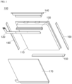
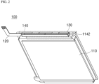
- a heat radiation tape 130 is attached in a shape of wrapping a protection circuit module 120 to form a predetermined heat radiation structure, and thus the protection circuit module 120 may be installed on a cell terrace part 1142 extending from one side of a plate-shaped battery cell 110.
- the heat radiation tape may be attached in a shape of wrapping the protection circuit module 120 to form a first contact part 130a which is in contact with the upper surface of the protection circuit module 120, a second contact part 130b which is in contact with a region between the side surface of the protection circuit module 120 and the upper end surface of the battery cell 110 in a shape of being bent and extending from the first contact part 130a, a third contact part 130c which is in contact with a region between the lower surface of the protection circuit module 120 and the upper surface of the cell terrace part 1142 in a shape of being bent and extending from the second contact part 130b, a fourth contact part 130d which is in contact with the side portion of the cell terrace part 1142 in a shape of being bent and extending from the third contact part 130c, and a fifth contact part 130e which is in contact with the lower surface of the cell terrace part 1142 in a shape of being bent and extending from the fourth contact part 130d.
- the protection circuit module 120 has a structure which is applied to a battery pack having a charging current of 2.0 C or greater and in which two of FETs 1221, 1222, 1223, and 1224 are installed on each of the upper surface or the lower surface thereof as shown in FIG. 3A and FIG. 3B .
- a heating level by an FET which is a main heating factor is high.
- a heating level may be effectively reduced through the heat radiation structure of the heat radiation tape 130 as described above.
- a side surface covering step the side surfaces of the battery cell 110 are covered by attaching a side surface tape 160 to each of both side surfaces of the battery cell 110.
- a front surface tape is attached to the front surface of the battery cell 110.
- a pad print (not shown) indicating pack information including a serial number or the like of a battery pack 100 may be attached to the upper surface of the front surface tape after the front surface tape is attached.
Landscapes
- Chemical & Material Sciences (AREA)
- Chemical Kinetics & Catalysis (AREA)
- Electrochemistry (AREA)
- General Chemical & Material Sciences (AREA)
- Engineering & Computer Science (AREA)
- Manufacturing & Machinery (AREA)
- Microelectronics & Electronic Packaging (AREA)
- Battery Mounting, Suspending (AREA)
- Secondary Cells (AREA)
Claims (13)
- Batteriepack, umfassend:eine plattenförmige Batteriezelle, welche einen Zellenabsatzteil umfasst, welcher sich an einer Seitenfläche davon aufwärts erstreckt, und welche ein Paar Elektrodenkontakte aufweist, welche nach außen durch den Zellenabsatzteil hervorstehen;ein Schutzkreismodul (PCM), welches zwei FETs umfasst, welche an jeder der oberen und unteren Fläche davon angeordnet sind, und welches an dem Zellenabsatzteil installiert ist,ein Wärmeabstrahlband, welches angebracht ist, während es das Schutzkreismodul (PCM) in einer ""-Form einhüllt, um einen Kontaktbereich an jedem von der Seitenfläche der Batteriezelle, einem Bereich zwischen dem Schutzkreismodul (PCM) und dem Zellenabsatzteil, sowie dem oberen Abschnitt des Schutzkreismoduls (PMC) zu bilden; und
 ein oberes Band, welches den oberen Abschnitt des Schutzkreismoduls (PCM) bedeckt, welches durch das Wärmeabstrahlband eingehüllt ist.
 - Batteriepack nach Anspruch 1, ferner umfassend:ein unteres Band, welches die untere Fläche der Batteriezelle bedeckt;ein Seitenflächenband, welches jede der beiden Seitenflächen der Batteriezelle bedeckt; undein Vorderflächenband, welches an der Vorderfläche der Batteriezelle angebracht ist.
- Batteriepack nach Anspruch 1, wobei das Wärmeabstrahlband umfasst:einen ersten Kontaktteil, welcher mit der oberen Fläche des Schutzkreismoduls (PCM) in Kontakt steht;einen zweiten Kontaktteil, welcher mit einem Bereich zwischen der Seitenfläche des Schutzkreismoduls (PCM) und der oberen Endfläche der Batteriezelle in einer Form in Kontakt steht, in welcher er gebogen ist und von dem ersten Kontaktteil hervorsteht;einen dritten Kontaktteil, welcher mit einem Bereich zwischen der unteren Fläche des Schutzkreismoduls (PCM) und der oberen Fläche des Zellenabsatzteils in einer Form in Kontakt steht, in welcher er gebogen ist und von dem zweiten Kontaktteil hervorsteht;einen vierten Kontaktteil, welcher mit dem Seitenabschnitt des Zellenabsatzteils in einer Form in Kontakt steht, in welcher er gebogen ist und von dem dritten Kontaktteil hervorsteht; undeinen fünften Kontaktteil, welche mit der unteren Fläche des Zellenabsatzteils in einer Form in Kontakt steht, in welcher er gebogen ist und von dem vierten Kontaktteil hervorsteht.
- Batteriepack nach Anspruch 3, wobei das Wärmeabstrahlband einen FET-Generations-Wärme-Transferpfad bildet, durch welchen Wärme, welche durch den FET des Schutzkreismoduls (PCM) generiert ist, in die Richtung von dem ersten Kontaktteil zu dem fünften Kontaktteil fließt.
- Batteriepack nach Anspruch 4, wobei Wärme, welche durch den FET-Generations-Wärme-Transferpfad fließt, abgegeben ist, nachdem sie durch jeden von dem ersten Kontaktteil, dem vierten Kontaktteil und dem fünften Kontaktteil dispergiert ist.
- Batteriepack nach Anspruch 4, wobei das Wärmeabstrahlband aus einem Material gefertigt ist, welches eine hohe Wärmeleitfähigkeit aufweist.
- Batteriepack nach Anspruch 6, wobei das Wärmeabstrahlband aus einem Graphitband oder einem synthetischen Band gefertigt ist, welches Aluminium (Al) umfasst.
- Verfahren zum Herstellen eines Batteriepacks umfassend eine Struktur, welche Wärme abstrahlt, welche von einem FET generiert wird, welcher an einem Schutzkreismodul (PCM) installiert ist, wobei das Verfahren umfasst:einen Schutzkreismodulinstallationsschritt eines Installierens des Schutzkreismoduls (PCM) an einem Zellenabsatzteil durch Verwenden eines Wärmeabstrahlbands, welches eine ""-Form aufweist, um einen Kontaktbereich an jedem von der Seitenfläche einer Batteriezelle, einem Bereich zwischen dem Schutzkreismodul (PCM) und dem Zellenabsatzteil, welcher sich aufwärts an einer Seitenfläche der Batteriezelle erstreckt, sowie dem oberen Abschnitt des Schutzkreismoduls (PCM) zu bilden;
 einen Seitenflächenbedeckungsschritt eines Bedeckens von beiden Seitenflächen der Batteriezelle durch Anbringen eines Seitenflächenbands an jeder der beiden Seitenflächen der Batteriezelle;einen oberen und unteren Abschnittbedeckungsschritt eines entsprechenden Anbringens von oberen und unteren Bändern an dem oberen und unteren Abschnitt der Batteriezelle, um den oberen und unteren Abschnitt der Batteriezelle zu bedecken; undeinen Vorderflächenbedeckungsschritt eines Anbringens eines Vorderflächenbands an der Vorderfläche der Batteriezelle, um die Vorderfläche der Batteriezelle zu bedecken.
 - Verfahren nach Anspruch 8, wobei, in dem Schutzkreismodulinstallationsschritt, das Wärmeabstrahlband angebracht wird in einer Struktur eines Bildens eines ersten Kontaktteils, welcher mit der oberen Fläche des Schutzkreismoduls (PCM) in Kontakt steht, eines zweiten Kontaktteils, welcher mit einem Bereich zwischen der Seitenfläche des Schutzkreismoduls (PCM) und der oberen Endfläche der Batteriezelle in einer Form in Kontakt steht, in welcher er gebogen ist und von dem ersten Kontaktteil hervorsteht, eines dritten Kontaktteils, welcher mit einem Bereich zwischen der unteren Fläche des Schutzkreismoduls (PCM) und der oberen Fläche des Zellenabsatzteils in einer Form in Kontakt steht, in welcher er gebogen ist und von dem zweiten Kontaktteil hervorsteht, eines vierten Kontaktteils, welcher mit dem Seitenabschnitt des Zellenabsatzteils in einer Form in Kontakt steht, in welcher er gebogen ist und von dem dritten Kontaktteil hervorsteht, und eines fünften Kontaktteils, welcher mit der unteren Fläche des Zellenabsatzteils in einer Form in Kontakt steht, in welcher er gebogen ist und von dem vierten Kontaktteil hervorsteht.
- Verfahren nach Anspruch 9, wobei das Wärmeabstrahlband einen FET-Generations-Wärme-Transferpfad bildet, durch welchen Wärme, welche durch den FET des Schutzkreismoduls (PCM) generiert wird, in die Richtung von dem ersten Kontaktteil zu dem fünften Kontaktteil fließt.
- Verfahren nach Anspruch 10, wobei die Wärme, welche durch den FET-Generations-Wärme-Transferpfad fließt, abgegeben wird, nachdem sie durch jeden von dem ersten Kontaktteil, dem vierten Kontaktteil und dem fünften Kontaktteil dispergiert wurde.
- Verfahren nach Anspruch 10, wobei das Wärmeabstrahlband aus einem Material gefertigt ist, welches eine hohe Wärmeleitfähigkeit aufweist.
- Verfahren nach Anspruch 12, wobei das Wärmeabstrahlband aus einem Graphitband oder einem synthetischen Band gefertigt ist, welches Aluminium (Al) umfasst.
Applications Claiming Priority (2)
| Application Number | Priority Date | Filing Date | Title |
|---|---|---|---|
| KR1020200142241A KR102755060B1 (ko) | 2020-10-29 | 2020-10-29 | 방열 테이프를 이용한 보호회로 모듈 방열 구조를 포함하는 전지팩 |
| PCT/KR2021/015102 WO2022092765A1 (ko) | 2020-10-29 | 2021-10-26 | 방열 테이프를 이용한 보호회로 모듈 방열 구조를 포함하는 전지팩 |
Publications (3)
| Publication Number | Publication Date |
|---|---|
| EP4099489A1 EP4099489A1 (de) | 2022-12-07 |
| EP4099489A4 EP4099489A4 (de) | 2024-07-31 |
| EP4099489B1 true EP4099489B1 (de) | 2025-04-16 |
Family
ID=81382835
Family Applications (1)
| Application Number | Title | Priority Date | Filing Date |
|---|---|---|---|
| EP21886759.6A Active EP4099489B1 (de) | 2020-10-29 | 2021-10-26 | Batteriepack mit wärmeableitungsstruktur eines schutzschaltungsmoduls unter verwendung eines wärmeableitbandes |
Country Status (9)
| Country | Link |
|---|---|
| US (1) | US20240204302A1 (de) |
| EP (1) | EP4099489B1 (de) |
| JP (1) | JP7504207B2 (de) |
| KR (1) | KR102755060B1 (de) |
| CN (1) | CN116648820A (de) |
| ES (1) | ES3026435T3 (de) |
| HU (1) | HUE071116T2 (de) |
| TW (1) | TWI881185B (de) |
| WO (1) | WO2022092765A1 (de) |
Families Citing this family (2)
| Publication number | Priority date | Publication date | Assignee | Title |
|---|---|---|---|---|
| KR102917726B1 (ko) * | 2022-09-15 | 2026-01-23 | 삼성에스디아이 주식회사 | 방열 구조를 포함하는 배터리 팩 |
| KR20250137881A (ko) * | 2024-03-12 | 2025-09-19 | 삼성에스디아이 주식회사 | 배터리 팩 |
Family Cites Families (20)
| Publication number | Priority date | Publication date | Assignee | Title |
|---|---|---|---|---|
| JP3727840B2 (ja) * | 2000-09-29 | 2005-12-21 | 株式会社東芝 | 電池パック及び携帯用電子機器 |
| KR100686814B1 (ko) | 2005-04-26 | 2007-02-26 | 삼성에스디아이 주식회사 | 폴리머 배터리 팩 및 그 제조 방법 |
| US8916278B2 (en) * | 2009-08-12 | 2014-12-23 | Samsung Sdi Co., Ltd. | Heat transfer member for battery pack |
| KR101075304B1 (ko) | 2009-10-09 | 2011-10-19 | 삼성에스디아이 주식회사 | 배터리 팩 및 그 제조 방법 |
| US9065085B2 (en) * | 2011-04-19 | 2015-06-23 | Samsung Sdi Co., Ltd. | Battery pack |
| KR101539691B1 (ko) * | 2012-10-19 | 2015-07-27 | 주식회사 엘지화학 | 파우치형 이차 전지의 프레임, 이를 포함하는 배터리 팩 및 배터리 팩의 제조 방법 |
| KR102030111B1 (ko) * | 2013-09-04 | 2019-10-08 | 삼성에스디아이 주식회사 | 배터리 팩 |
| JP2015088381A (ja) | 2013-10-31 | 2015-05-07 | 日立マクセル株式会社 | 電池パック |
| KR20160039790A (ko) * | 2014-10-02 | 2016-04-12 | 주식회사 아이티엠반도체 | 배터리 보호회로 패키지 |
| KR101794941B1 (ko) * | 2014-12-04 | 2017-12-01 | 주식회사 엘지화학 | 방열 테이프를 포함하고 있는 보호회로모듈 |
| KR20160109428A (ko) | 2015-03-11 | 2016-09-21 | 삼성에스디아이 주식회사 | 배터리 팩 |
| KR102434771B1 (ko) * | 2015-08-28 | 2022-08-22 | 삼성에스디아이 주식회사 | 배터리 팩 |
| KR102067713B1 (ko) | 2016-05-31 | 2020-01-17 | 주식회사 엘지화학 | 배터리 모듈 및 이를 포함하는 배터리 팩, 자동차 |
| KR102362074B1 (ko) * | 2017-03-10 | 2022-02-11 | 삼성전자주식회사 | 방열 플레이트를 포함하는 배터리 및 이를 포함하는 전자 장치 |
| KR102332332B1 (ko) * | 2017-06-16 | 2021-11-29 | 삼성에스디아이 주식회사 | 배터리 팩 |
| WO2019073879A1 (ja) * | 2017-10-12 | 2019-04-18 | マクセルホールディングス株式会社 | ラミネート型電池 |
| US11670805B2 (en) | 2017-10-31 | 2023-06-06 | Snap Inc. | Nested PCM battery pack |
| CN208142271U (zh) * | 2017-12-29 | 2018-11-23 | 宁德新能源科技有限公司 | 一种电芯及电池 |
| JP7063661B2 (ja) * | 2018-03-14 | 2022-05-09 | マクセル株式会社 | ラミネート型電池 |
| CN209071559U (zh) * | 2018-11-15 | 2019-07-05 | 宁德时代新能源科技股份有限公司 | 电池监控单元及电池包 |
-
2020
- 2020-10-29 KR KR1020200142241A patent/KR102755060B1/ko active Active
-
2021
- 2021-10-26 US US17/909,863 patent/US20240204302A1/en active Pending
- 2021-10-26 EP EP21886759.6A patent/EP4099489B1/de active Active
- 2021-10-26 ES ES21886759T patent/ES3026435T3/es active Active
- 2021-10-26 WO PCT/KR2021/015102 patent/WO2022092765A1/ko not_active Ceased
- 2021-10-26 CN CN202180061175.1A patent/CN116648820A/zh active Pending
- 2021-10-26 JP JP2022543573A patent/JP7504207B2/ja active Active
- 2021-10-26 HU HUE21886759A patent/HUE071116T2/hu unknown
- 2021-10-27 TW TW110139811A patent/TWI881185B/zh active
Also Published As
| Publication number | Publication date |
|---|---|
| EP4099489A4 (de) | 2024-07-31 |
| US20240204302A1 (en) | 2024-06-20 |
| KR102755060B1 (ko) | 2025-01-20 |
| HUE071116T2 (hu) | 2025-08-28 |
| TW202218228A (zh) | 2022-05-01 |
| EP4099489A1 (de) | 2022-12-07 |
| JP2023511099A (ja) | 2023-03-16 |
| TWI881185B (zh) | 2025-04-21 |
| KR20220057206A (ko) | 2022-05-09 |
| JP7504207B2 (ja) | 2024-06-21 |
| CN116648820A (zh) | 2023-08-25 |
| WO2022092765A1 (ko) | 2022-05-05 |
| ES3026435T3 (en) | 2025-06-11 |
Similar Documents
| Publication | Publication Date | Title |
|---|---|---|
| US8568910B2 (en) | Protective circuit module for secondary battery and battery pack using the same | |
| EP2200111B1 (de) | Batteriepack | |
| KR101329834B1 (ko) | 배터리 팩 | |
| EP2579384B1 (de) | Wiederaufladbare Batterie | |
| US10074834B2 (en) | Battery pack for reducing damage from external static electricity | |
| CN101764247B (zh) | 电池组 | |
| US9786958B2 (en) | Rechargeable battery with temperature-protecting element | |
| EP4099489B1 (de) | Batteriepack mit wärmeableitungsstruktur eines schutzschaltungsmoduls unter verwendung eines wärmeableitbandes | |
| CN103165833B (zh) | 电池组 | |
| CN100448068C (zh) | 用于二次电池的二次保护元件 | |
| US12482872B2 (en) | Battery module and battery pack including the same | |
| KR101430618B1 (ko) | 배터리 팩 및 이를 구비한 전자 기기 | |
| JP7038946B2 (ja) | バッテリーパック及びこの製造方法 | |
| CN102082241B (zh) | 二次电池 | |
| JP2023531997A (ja) | バッテリーパック及びそれを含む電子デバイス | |
| CN104064825A (zh) | 用于电池组的保护装置、制造保护装置的方法及电池组 | |
| KR20140038037A (ko) | 배터리 팩 | |
| CN210668435U (zh) | 电池及电子设备 | |
| CN218827319U (zh) | 电池和电子设备 | |
| WO2024109266A1 (zh) | 电池和电子设备 | |
| JP2001052751A (ja) | 固体状電解質二次電池ユニット | |
| KR20060097484A (ko) | 안테나 패턴을 갖는 이차 전지 | |
| CN106129285A (zh) | 电池组 |
Legal Events
| Date | Code | Title | Description |
|---|---|---|---|
| STAA | Information on the status of an ep patent application or granted ep patent |
Free format text: STATUS: THE INTERNATIONAL PUBLICATION HAS BEEN MADE |
|
| PUAI | Public reference made under article 153(3) epc to a published international application that has entered the european phase |
Free format text: ORIGINAL CODE: 0009012 |
|
| STAA | Information on the status of an ep patent application or granted ep patent |
Free format text: STATUS: REQUEST FOR EXAMINATION WAS MADE |
|
| 17P | Request for examination filed |
Effective date: 20220902 |
|
| AK | Designated contracting states |
Kind code of ref document: A1 Designated state(s): AL AT BE BG CH CY CZ DE DK EE ES FI FR GB GR HR HU IE IS IT LI LT LU LV MC MK MT NL NO PL PT RO RS SE SI SK SM TR |
|
| DAV | Request for validation of the european patent (deleted) | ||
| DAX | Request for extension of the european patent (deleted) | ||
| A4 | Supplementary search report drawn up and despatched |
Effective date: 20240628 |
|
| RIC1 | Information provided on ipc code assigned before grant |
Ipc: H01M 10/667 20140101ALI20240624BHEP Ipc: H01M 10/42 20060101ALI20240624BHEP Ipc: H01M 50/572 20210101ALI20240624BHEP Ipc: H01M 50/209 20210101AFI20240624BHEP |
|
| GRAP | Despatch of communication of intention to grant a patent |
Free format text: ORIGINAL CODE: EPIDOSNIGR1 |
|
| STAA | Information on the status of an ep patent application or granted ep patent |
Free format text: STATUS: GRANT OF PATENT IS INTENDED |
|
| INTG | Intention to grant announced |
Effective date: 20250114 |
|
| GRAS | Grant fee paid |
Free format text: ORIGINAL CODE: EPIDOSNIGR3 |
|
| P01 | Opt-out of the competence of the unified patent court (upc) registered |
Free format text: CASE NUMBER: APP_6057/2025 Effective date: 20250205 |
|
| GRAA | (expected) grant |
Free format text: ORIGINAL CODE: 0009210 |
|
| STAA | Information on the status of an ep patent application or granted ep patent |
Free format text: STATUS: THE PATENT HAS BEEN GRANTED |
|
| AK | Designated contracting states |
Kind code of ref document: B1 Designated state(s): AL AT BE BG CH CY CZ DE DK EE ES FI FR GB GR HR HU IE IS IT LI LT LU LV MC MK MT NL NO PL PT RO RS SE SI SK SM TR |
|
| REG | Reference to a national code |
Ref country code: GB Ref legal event code: FG4D |
|
| REG | Reference to a national code |
Ref country code: CH Ref legal event code: EP |
|
| REG | Reference to a national code |
Ref country code: IE Ref legal event code: FG4D |
|
| REG | Reference to a national code |
Ref country code: DE Ref legal event code: R096 Ref document number: 602021029393 Country of ref document: DE |
|
| REG | Reference to a national code |
Ref country code: ES Ref legal event code: FG2A Ref document number: 3026435 Country of ref document: ES Kind code of ref document: T3 Effective date: 20250611 |
|
| REG | Reference to a national code |
Ref country code: NL Ref legal event code: MP Effective date: 20250416 |
|
| REG | Reference to a national code |
Ref country code: HU Ref legal event code: AG4A Ref document number: E071116 Country of ref document: HU |
|
| PG25 | Lapsed in a contracting state [announced via postgrant information from national office to epo] |
Ref country code: NL Free format text: LAPSE BECAUSE OF FAILURE TO SUBMIT A TRANSLATION OF THE DESCRIPTION OR TO PAY THE FEE WITHIN THE PRESCRIBED TIME-LIMIT Effective date: 20250416 |
|
| REG | Reference to a national code |
Ref country code: AT Ref legal event code: MK05 Ref document number: 1786440 Country of ref document: AT Kind code of ref document: T Effective date: 20250416 |
|
| PG25 | Lapsed in a contracting state [announced via postgrant information from national office to epo] |
Ref country code: FI Free format text: LAPSE BECAUSE OF FAILURE TO SUBMIT A TRANSLATION OF THE DESCRIPTION OR TO PAY THE FEE WITHIN THE PRESCRIBED TIME-LIMIT Effective date: 20250416 Ref country code: PT Free format text: LAPSE BECAUSE OF FAILURE TO SUBMIT A TRANSLATION OF THE DESCRIPTION OR TO PAY THE FEE WITHIN THE PRESCRIBED TIME-LIMIT Effective date: 20250818 |
|
| REG | Reference to a national code |
Ref country code: LT Ref legal event code: MG9D |
|
| PG25 | Lapsed in a contracting state [announced via postgrant information from national office to epo] |
Ref country code: NO Free format text: LAPSE BECAUSE OF FAILURE TO SUBMIT A TRANSLATION OF THE DESCRIPTION OR TO PAY THE FEE WITHIN THE PRESCRIBED TIME-LIMIT Effective date: 20250716 Ref country code: GR Free format text: LAPSE BECAUSE OF FAILURE TO SUBMIT A TRANSLATION OF THE DESCRIPTION OR TO PAY THE FEE WITHIN THE PRESCRIBED TIME-LIMIT Effective date: 20250717 |
|
| PG25 | Lapsed in a contracting state [announced via postgrant information from national office to epo] |
Ref country code: PL Free format text: LAPSE BECAUSE OF FAILURE TO SUBMIT A TRANSLATION OF THE DESCRIPTION OR TO PAY THE FEE WITHIN THE PRESCRIBED TIME-LIMIT Effective date: 20250416 |
|
| PG25 | Lapsed in a contracting state [announced via postgrant information from national office to epo] |
Ref country code: BG Free format text: LAPSE BECAUSE OF FAILURE TO SUBMIT A TRANSLATION OF THE DESCRIPTION OR TO PAY THE FEE WITHIN THE PRESCRIBED TIME-LIMIT Effective date: 20250416 |
|
| PGFP | Annual fee paid to national office [announced via postgrant information from national office to epo] |
Ref country code: BE Payment date: 20250922 Year of fee payment: 5 Ref country code: GB Payment date: 20250922 Year of fee payment: 5 |
|
| PG25 | Lapsed in a contracting state [announced via postgrant information from national office to epo] |
Ref country code: HR Free format text: LAPSE BECAUSE OF FAILURE TO SUBMIT A TRANSLATION OF THE DESCRIPTION OR TO PAY THE FEE WITHIN THE PRESCRIBED TIME-LIMIT Effective date: 20250416 |
|
| PG25 | Lapsed in a contracting state [announced via postgrant information from national office to epo] |
Ref country code: AT Free format text: LAPSE BECAUSE OF FAILURE TO SUBMIT A TRANSLATION OF THE DESCRIPTION OR TO PAY THE FEE WITHIN THE PRESCRIBED TIME-LIMIT Effective date: 20250416 |
|
| PGFP | Annual fee paid to national office [announced via postgrant information from national office to epo] |
Ref country code: FR Payment date: 20250925 Year of fee payment: 5 |
|
| PG25 | Lapsed in a contracting state [announced via postgrant information from national office to epo] |
Ref country code: RS Free format text: LAPSE BECAUSE OF FAILURE TO SUBMIT A TRANSLATION OF THE DESCRIPTION OR TO PAY THE FEE WITHIN THE PRESCRIBED TIME-LIMIT Effective date: 20250716 |
|
| PG25 | Lapsed in a contracting state [announced via postgrant information from national office to epo] |
Ref country code: IS Free format text: LAPSE BECAUSE OF FAILURE TO SUBMIT A TRANSLATION OF THE DESCRIPTION OR TO PAY THE FEE WITHIN THE PRESCRIBED TIME-LIMIT Effective date: 20250816 |
|
| PG25 | Lapsed in a contracting state [announced via postgrant information from national office to epo] |
Ref country code: LV Free format text: LAPSE BECAUSE OF FAILURE TO SUBMIT A TRANSLATION OF THE DESCRIPTION OR TO PAY THE FEE WITHIN THE PRESCRIBED TIME-LIMIT Effective date: 20250416 |
|
| PGFP | Annual fee paid to national office [announced via postgrant information from national office to epo] |
Ref country code: HU Payment date: 20251029 Year of fee payment: 5 |
|
| PGFP | Annual fee paid to national office [announced via postgrant information from national office to epo] |
Ref country code: DE Payment date: 20250922 Year of fee payment: 5 |
|
| PG25 | Lapsed in a contracting state [announced via postgrant information from national office to epo] |
Ref country code: SM Free format text: LAPSE BECAUSE OF FAILURE TO SUBMIT A TRANSLATION OF THE DESCRIPTION OR TO PAY THE FEE WITHIN THE PRESCRIBED TIME-LIMIT Effective date: 20250416 Ref country code: DK Free format text: LAPSE BECAUSE OF FAILURE TO SUBMIT A TRANSLATION OF THE DESCRIPTION OR TO PAY THE FEE WITHIN THE PRESCRIBED TIME-LIMIT Effective date: 20250416 |
|
| REG | Reference to a national code |
Ref country code: DE Ref legal event code: R097 Ref document number: 602021029393 Country of ref document: DE |
|
| PG25 | Lapsed in a contracting state [announced via postgrant information from national office to epo] |
Ref country code: CZ Free format text: LAPSE BECAUSE OF FAILURE TO SUBMIT A TRANSLATION OF THE DESCRIPTION OR TO PAY THE FEE WITHIN THE PRESCRIBED TIME-LIMIT Effective date: 20250416 |
|
| PG25 | Lapsed in a contracting state [announced via postgrant information from national office to epo] |
Ref country code: EE Free format text: LAPSE BECAUSE OF FAILURE TO SUBMIT A TRANSLATION OF THE DESCRIPTION OR TO PAY THE FEE WITHIN THE PRESCRIBED TIME-LIMIT Effective date: 20250416 |
|
| PG25 | Lapsed in a contracting state [announced via postgrant information from national office to epo] |
Ref country code: SK Free format text: LAPSE BECAUSE OF FAILURE TO SUBMIT A TRANSLATION OF THE DESCRIPTION OR TO PAY THE FEE WITHIN THE PRESCRIBED TIME-LIMIT Effective date: 20250416 |
|
| PG25 | Lapsed in a contracting state [announced via postgrant information from national office to epo] |
Ref country code: IT Free format text: LAPSE BECAUSE OF FAILURE TO SUBMIT A TRANSLATION OF THE DESCRIPTION OR TO PAY THE FEE WITHIN THE PRESCRIBED TIME-LIMIT Effective date: 20250416 |
|
| PGFP | Annual fee paid to national office [announced via postgrant information from national office to epo] |
Ref country code: ES Payment date: 20251117 Year of fee payment: 5 |
|
| PG25 | Lapsed in a contracting state [announced via postgrant information from national office to epo] |
Ref country code: RO Free format text: LAPSE BECAUSE OF FAILURE TO SUBMIT A TRANSLATION OF THE DESCRIPTION OR TO PAY THE FEE WITHIN THE PRESCRIBED TIME-LIMIT Effective date: 20250416 |
|
| PLBE | No opposition filed within time limit |
Free format text: ORIGINAL CODE: 0009261 |
|
| STAA | Information on the status of an ep patent application or granted ep patent |
Free format text: STATUS: NO OPPOSITION FILED WITHIN TIME LIMIT |
|
| REG | Reference to a national code |
Ref country code: CH Ref legal event code: L10 Free format text: ST27 STATUS EVENT CODE: U-0-0-L10-L00 (AS PROVIDED BY THE NATIONAL OFFICE) Effective date: 20260225 |
|
| 26N | No opposition filed |
Effective date: 20260119 |