EP4099429B1 - Sekundärbatterie mit wasserfreiem elektrolyten - Google Patents
Sekundärbatterie mit wasserfreiem elektrolyten Download PDFInfo
- Publication number
- EP4099429B1 EP4099429B1 EP21746969.1A EP21746969A EP4099429B1 EP 4099429 B1 EP4099429 B1 EP 4099429B1 EP 21746969 A EP21746969 A EP 21746969A EP 4099429 B1 EP4099429 B1 EP 4099429B1
- Authority
- EP
- European Patent Office
- Prior art keywords
- negative electrode
- coated portion
- surface coated
- mixture layer
- current collector
- Prior art date
- Legal status (The legal status is an assumption and is not a legal conclusion. Google has not performed a legal analysis and makes no representation as to the accuracy of the status listed.)
- Active
Links
Images


Classifications
-
- H—ELECTRICITY
- H01—ELECTRIC ELEMENTS
- H01M—PROCESSES OR MEANS, e.g. BATTERIES, FOR THE DIRECT CONVERSION OF CHEMICAL ENERGY INTO ELECTRICAL ENERGY
- H01M4/00—Electrodes
- H01M4/02—Electrodes composed of, or comprising, active material
- H01M4/13—Electrodes for accumulators with non-aqueous electrolyte, e.g. for lithium-accumulators; Processes of manufacture thereof
- H01M4/134—Electrodes based on metals, Si or alloys
-
- H—ELECTRICITY
- H01—ELECTRIC ELEMENTS
- H01M—PROCESSES OR MEANS, e.g. BATTERIES, FOR THE DIRECT CONVERSION OF CHEMICAL ENERGY INTO ELECTRICAL ENERGY
- H01M10/00—Secondary cells; Manufacture thereof
- H01M10/04—Construction or manufacture in general
- H01M10/0431—Cells with wound or folded electrodes
-
- H—ELECTRICITY
- H01—ELECTRIC ELEMENTS
- H01M—PROCESSES OR MEANS, e.g. BATTERIES, FOR THE DIRECT CONVERSION OF CHEMICAL ENERGY INTO ELECTRICAL ENERGY
- H01M10/00—Secondary cells; Manufacture thereof
- H01M10/05—Accumulators with non-aqueous electrolyte
- H01M10/052—Li-accumulators
- H01M10/0525—Rocking-chair batteries, i.e. batteries with lithium insertion or intercalation in both electrodes; Lithium-ion batteries
-
- H—ELECTRICITY
- H01—ELECTRIC ELEMENTS
- H01M—PROCESSES OR MEANS, e.g. BATTERIES, FOR THE DIRECT CONVERSION OF CHEMICAL ENERGY INTO ELECTRICAL ENERGY
- H01M10/00—Secondary cells; Manufacture thereof
- H01M10/05—Accumulators with non-aqueous electrolyte
- H01M10/058—Construction or manufacture
- H01M10/0587—Construction or manufacture of accumulators having only wound construction elements, i.e. wound positive electrodes, wound negative electrodes and wound separators
-
- H—ELECTRICITY
- H01—ELECTRIC ELEMENTS
- H01M—PROCESSES OR MEANS, e.g. BATTERIES, FOR THE DIRECT CONVERSION OF CHEMICAL ENERGY INTO ELECTRICAL ENERGY
- H01M4/00—Electrodes
- H01M4/02—Electrodes composed of, or comprising, active material
- H01M4/04—Processes of manufacture in general
- H01M4/0402—Methods of deposition of the material
- H01M4/0404—Methods of deposition of the material by coating on electrode collectors
-
- H—ELECTRICITY
- H01—ELECTRIC ELEMENTS
- H01M—PROCESSES OR MEANS, e.g. BATTERIES, FOR THE DIRECT CONVERSION OF CHEMICAL ENERGY INTO ELECTRICAL ENERGY
- H01M4/00—Electrodes
- H01M4/02—Electrodes composed of, or comprising, active material
- H01M4/36—Selection of substances as active materials, active masses, active liquids
- H01M4/38—Selection of substances as active materials, active masses, active liquids of elements or alloys
- H01M4/386—Silicon or alloys based on silicon
-
- H—ELECTRICITY
- H01—ELECTRIC ELEMENTS
- H01M—PROCESSES OR MEANS, e.g. BATTERIES, FOR THE DIRECT CONVERSION OF CHEMICAL ENERGY INTO ELECTRICAL ENERGY
- H01M4/00—Electrodes
- H01M4/02—Electrodes composed of, or comprising, active material
- H01M4/62—Selection of inactive substances as ingredients for active masses, e.g. binders, fillers
- H01M4/621—Binders
- H01M4/622—Binders being polymers
-
- H—ELECTRICITY
- H01—ELECTRIC ELEMENTS
- H01M—PROCESSES OR MEANS, e.g. BATTERIES, FOR THE DIRECT CONVERSION OF CHEMICAL ENERGY INTO ELECTRICAL ENERGY
- H01M4/00—Electrodes
- H01M4/02—Electrodes composed of, or comprising, active material
- H01M4/64—Carriers or collectors
- H01M4/70—Carriers or collectors characterised by shape or form
-
- H—ELECTRICITY
- H01—ELECTRIC ELEMENTS
- H01M—PROCESSES OR MEANS, e.g. BATTERIES, FOR THE DIRECT CONVERSION OF CHEMICAL ENERGY INTO ELECTRICAL ENERGY
- H01M50/00—Constructional details or processes of manufacture of the non-active parts of electrochemical cells other than fuel cells, e.g. hybrid cells
- H01M50/40—Separators; Membranes; Diaphragms; Spacing elements inside cells
- H01M50/46—Separators, membranes or diaphragms characterised by their combination with electrodes
-
- H—ELECTRICITY
- H01—ELECTRIC ELEMENTS
- H01M—PROCESSES OR MEANS, e.g. BATTERIES, FOR THE DIRECT CONVERSION OF CHEMICAL ENERGY INTO ELECTRICAL ENERGY
- H01M4/00—Electrodes
- H01M4/02—Electrodes composed of, or comprising, active material
- H01M2004/021—Physical characteristics, e.g. porosity, surface area
-
- H—ELECTRICITY
- H01—ELECTRIC ELEMENTS
- H01M—PROCESSES OR MEANS, e.g. BATTERIES, FOR THE DIRECT CONVERSION OF CHEMICAL ENERGY INTO ELECTRICAL ENERGY
- H01M4/00—Electrodes
- H01M4/02—Electrodes composed of, or comprising, active material
- H01M2004/026—Electrodes composed of, or comprising, active material characterised by the polarity
- H01M2004/027—Negative electrodes
-
- Y—GENERAL TAGGING OF NEW TECHNOLOGICAL DEVELOPMENTS; GENERAL TAGGING OF CROSS-SECTIONAL TECHNOLOGIES SPANNING OVER SEVERAL SECTIONS OF THE IPC; TECHNICAL SUBJECTS COVERED BY FORMER USPC CROSS-REFERENCE ART COLLECTIONS [XRACs] AND DIGESTS
- Y02—TECHNOLOGIES OR APPLICATIONS FOR MITIGATION OR ADAPTATION AGAINST CLIMATE CHANGE
- Y02E—REDUCTION OF GREENHOUSE GAS [GHG] EMISSIONS, RELATED TO ENERGY GENERATION, TRANSMISSION OR DISTRIBUTION
- Y02E60/00—Enabling technologies; Technologies with a potential or indirect contribution to GHG emissions mitigation
- Y02E60/10—Energy storage using batteries
-
- Y—GENERAL TAGGING OF NEW TECHNOLOGICAL DEVELOPMENTS; GENERAL TAGGING OF CROSS-SECTIONAL TECHNOLOGIES SPANNING OVER SEVERAL SECTIONS OF THE IPC; TECHNICAL SUBJECTS COVERED BY FORMER USPC CROSS-REFERENCE ART COLLECTIONS [XRACs] AND DIGESTS
- Y02—TECHNOLOGIES OR APPLICATIONS FOR MITIGATION OR ADAPTATION AGAINST CLIMATE CHANGE
- Y02P—CLIMATE CHANGE MITIGATION TECHNOLOGIES IN THE PRODUCTION OR PROCESSING OF GOODS
- Y02P70/00—Climate change mitigation technologies in the production process for final industrial or consumer products
- Y02P70/50—Manufacturing or production processes characterised by the final manufactured product
Definitions
- the present disclosure generally relates to a non-aqueous electrolyte secondary battery.
- a non-aqueous electrolyte secondary battery comprising a wound electrode assembly in which a band-shaped positive electrode and a band-shaped negative electrode are wound with a separator interposed therebetween and an outer housing can that houses the wound electrode assembly.
- the electrodes of the electrode assembly (the positive electrode and the negative electrode) in such a wound battery have a mixture layer including an active material and a binder on both surfaces of each metallic current collector, and the positive electrode and the negative electrode are wound with the separator interposed therebetween.
- the separator is disposed on the outermost circumference of the electrode assembly, the positive electrode is connected to a sealing assembly, which is to be an external terminal on the positive electrode side, with a positive electrode lead, and the negative electrode is connected to the outer housing can, which is to be an external terminal on the negative electrode side, with a negative electrode lead.
- a sealing assembly which is to be an external terminal on the positive electrode side, with a positive electrode lead
- the negative electrode is connected to the outer housing can, which is to be an external terminal on the negative electrode side, with a negative electrode lead.
- Patent Literature 1 describes that a negative electrode is disposed on the outermost circumference of an electrode assembly, a negative electrode current collector is exposed as a one-surface coated portion eliminating a negative electrode mixture layer on a surface on the outermost circumference side at this position, and the negative electrode current collector is directly contacted with an inner face of an outer housing can to be electrically connected.
- Patent Literatures 2-4 all disclose batteries comprising wound electrode assemblies in which the outer circumference comprises a bare current collector.
- the negative electrode mixture layer expands during charge, it is also considered to utilize this expansion during charge to strengthen the electrical connection between the negative electrode current collector and the inner face of the outer housing can. In this method, however, the negative electrode mixture layer significantly expands and contracts due to the charge and discharge, and deterioration due to the cycles, such as peeling between the active material and the current collector and isolating the active material which results in no contribution of the active material to the charge and discharge, is likely to be large.
- the present disclosure provides a non-aqueous electrolyte secondary battery in which a charge expansion coefficient of the negative electrode mixture layer in a one-surface coated portion, at least a part of which is disposed on the outermost circumference, is set to be large to inhibit the failure during assembly and deterioration with the charge-discharge cycle and to ensure the electrical connection between the exposed surface of the negative electrode current collector on the outermost circumference of the electrode assembly and the inner face of the outer housing can.
- a non-aqueous electrolyte secondary battery comprising: a wound electrode assembly in which a band-shaped positive electrode and a band-shaped negative electrode are wound with a separator interposed therebetween; and an outer housing can that houses the electrode assembly, wherein the positive electrode has a positive electrode mixture layer formed on a surface of a sheet-shaped positive electrode current collector, the negative electrode has a negative electrode mixture layer formed on a surface of a sheet-shaped negative electrode current collector, the negative electrode mixture layer includes a chargeable and dischargeable negative electrode active material and a binder, the negative electrode includes: a both-surface coated portion in which the negative electrode mixture layer is formed on both surfaces of the negative electrode current collector; and a one-surface coated portion in which the negative electrode mixture layer is formed on one surface of the negative electrode current collector, at least a part of the one-surface coated portion is disposed on an outermost circumference of the electrode assembly, at least a
- the non-aqueous electrolyte secondary battery according to the present disclosure can achieve a clearance between the electrode assembly and the inner face of the outer housing can during assembly, and can reduce the charge expansion coefficient of the entire negative electrode mixture layer.
- the failure during assembly and deterioration due to the charge-discharge cycles can be inhibited, and a good electrical connection can be achieved between the exposed surface of the negative electrode current collector and the inner face of the outer housing can.
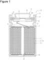
- FIG. 1 is an axial sectional view of a wound secondary battery 10 of an example of an embodiment.
- the secondary battery 10 illustrated in FIG. 1 has a cylindrical shape, the secondary battery 10 may have a rectangular cylindrical shape or the like as long as it is the wound battery.
- an electrode assembly 14 and a non-aqueous electrolyte (not illustrated) are housed in an outer housing can 15.
- the electrode assembly 14 has a wound structure in which a positive electrode 11 and a negative electrode 12 are wound with a separator 13 interposed therebetween.
- a non-aqueous solvent (organic solvent) of the non-aqueous electrolyte carbonates, lactones, ethers, ketones, esters, and the like may be used, and two or more of these solves may be mixed to be used.
- a mixed solvent including a cyclic carbonate and a linear carbonate is preferably used.
- ethylene carbonate (EC), propylene carbonate (PC), butylene carbonate (BC), and the like may be used as the cyclic carbonate
- DMC dimethyl carbonate
- EMC ethyl methyl carbonate
- DEC diethyl carbonate
- LiPF 6 LiPF 6 , LiBF 4 , LiCF 3 SO 3 , and the like, and a mixture thereof may be used.
- An amount of the electrolyte salt dissolved into the non-aqueous solvent may be set to be, for example, 0.5 to 2.0 mol/L.
- the sealing assembly 16 side will be described as “the upper side”
- the bottom side of the outer housing can 15 will be described as "the lower side”.
- An opening end part of the outer housing can 15 is capped with a sealing assembly 16 to seal inside the secondary battery 10.
- Insulating plates 17 and 18 are provided on the upper and lower sides of the electrode assembly 14, respectively.
- a positive electrode lead 19 extends upward through a through hole of the insulating plate 17, and welded with the lower face of a filter 22, which is a bottom plate of the sealing assembly 16.
- a negative electrode lead 20 extends through a through hole of the insulating plate 18 toward the bottom side of the outer housing can 15, and welded with a bottom inner face of the outer housing can 15.
- the outer housing can 15 becomes a negative electrode terminal.
- a negative electrode current collector 40 in a one-surface coated portion 46 is exposed on the outermost circumference of the electrode assembly 14, and the exposed surface of this negative electrode current collector 40 is contacted with the inner face of the outer housing can 15 to electrically connect the negative electrode 12 and the outer housing can 15.
- the outer housing can 15 is, for example, a bottomed cylindrical metallic outer housing can.
- a gasket 27 is provided between the outer housing can 15 and the sealing assembly 16 to electrically insulate the outer housing can 15 and the sealing assembly 16, and to achieve sealability inside the secondary battery 10.
- the outer housing can 15 has a grooved part 21 formed by, for example, pressing the side part thereof from the outside to support the sealing assembly 16.
- the grooved part 21 is preferably formed circularly along the circumferential direction of the outer housing can 15, and supports the sealing assembly 16 with the upper face of the grooved part 21.
- the sealing assembly 16 has the filter 22, a lower vent member 23, an insulating member 24, an upper vent member 25, and the cap 26 that are stacked in this order from the electrode assembly 14 side.
- Each member constituting the sealing assembly 16 has, for example, a disk shape or a ring shape, and each member except for the insulating member 24 is electrically connected each other.
- the lower vent member 23 and the upper vent member 25 are connected each other at each of central parts thereof, and the insulating member 24 is interposed between each of the circumferential parts thereof. If the internal pressure of the battery increases due to abnormal heat generation, for example, the lower vent member 23 breaks and thereby the upper vent member 25 expands toward the cap 26 side to be separated from the lower vent member 23, resulting in cutting off of an electrical connection between both the members. If the internal pressure further increases, the upper vent member 25 breaks, and gas is discharged through an opening 26a of the cap 26.
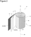
- FIG. 2 is a perspective view of the electrode assembly 14.
- the electrode assembly 14 has a wound structure in which the positive electrode 11 and the negative electrode 12 are spirally wound with the separator 13 interposed therebetween. Any of the positive electrode 11, the negative electrode 12, and the separator 13 is formed in a band shaped, and spirally wound around a winding core disposed along a winding axis 28 to be alternately stacked in the radial direction of the electrode assembly 14.
- the winding axis 28 side is referred to as the inner peripheral side, and the opposite side thereof is referred to as the outer peripheral side.
- the longitudinal direction of the positive electrode 11 and the negative electrode 12 becomes a winding direction
- the width direction of the positive electrode 11 and the negative electrode 12 becomes an axial direction.
- the positive electrode lead 19 extends, on the upper end of the electrode assembly 14 toward the axial direction, from a substantial center between the center and the outermost circumference in the radial direction.
- the negative electrode lead 20 extends, on the lower end of the electrode assembly 14, toward the axial direction from proximity of the winding axis 28.
- a porous sheet having an ion permeation property and an insulation property is used.
- the porous sheet include a fine porous thin film, a woven fabric, and a nonwoven fabric.
- olefin resins such as polyethylene and polypropylene are preferable.
- a thickness of the separator 13 is, for example, 10 ⁇ m to 50 ⁇ m.
- the separator 13 has tended to be thinned as higher capacity and higher output of the battery.
- the separator 13 has a melting point of, for example, approximately 130°C to 180°C.
- FIG. 3 is a front view of the positive electrode 11 constituting the electrode assembly 14 illustrated with an unwound state.
- the positive electrode 11 has a band-shaped positive electrode current collector 30 and a positive electrode mixture layer 32 formed on the positive electrode current collector 30.
- the positive electrode mixture layer 32 is formed on at least one of the inner peripheral side and outer peripheral side of the positive electrode current collector 30.
- a foil of a metal, such as aluminum, a film in which such a metal is disposed on a surface layer thereof, and the like are used, for example.
- a preferable positive electrode current collector 30 is a foil of metal mainly composed of aluminum or an aluminum alloy.
- a thickness of the positive electrode current collector 30 is, for example, 10 ⁇ m to 30 ⁇ m.
- the positive electrode mixture layer 32 is preferably formed on an entire region of both surfaces of the positive electrode current collector 30 except for a positive electrode current collector exposed part 34, described later.
- the positive electrode mixture layer 32 preferably includes a positive electrode active material, a conductive agent, and a binder.
- the positive electrode mixture layer 32 is formed by applying a positive electrode mixture slurry including the positive electrode active material, the conductive agent, the binder, and a solvent such as N-methyl-2-pyrrolidone (NMP) on both the surfaces of the positive electrode current collector 30 and drying thereof (positive electrode mixture layer forming step). Then, the positive electrode mixture layer 32 is compressed.
- NMP N-methyl-2-pyrrolidone
- the positive electrode active material may include a lithium-containing transition metal oxide containing a transition metal element such as Co, Mn, and Ni.
- the lithium-containing transition metal oxide is not particularly limited, and preferably a composite oxide represented by the general formula Li 1+x MO 2 (in the formula, -0.2 ⁇ x ⁇ 0.2 and M includes at least one of Ni, Co, Mn, and Al).
- Examples of the conductive agent included in the positive electrode mixture layer 32 may include carbon materials such as carbon black (CB), acetylene black (AB), Ketjenblack, and graphite.
- carbon black CB
- AB acetylene black
- Ketjenblack Ketjenblack
- graphite graphite
- binder included in the positive electrode mixture layer 32 examples include fluororesins such as polytetrafluoroethylene (PTFE) and polyvinylidene fluoride (PVdF), polyacrylonitrile (PAN), a polyimide (PI), an acrylic resin, and a polyolefinic resin.
- PTFE polytetrafluoroethylene
- PVdF polyvinylidene fluoride
- PAN polyacrylonitrile
- PI polyimide
- acrylic resin an acrylic resin
- polyolefinic resin a polyolefinic resin.
- the binder is preferably a rubber resin having a repeating molecular structure of double bonds and single bonds, such as SBR and NBR, from a viewpoint of flexibility of the positive electrode 11. These materials may be used singly, or may be used in combination of two or more thereof.
- a content of the binder in the positive electrode mixture layer 32 is 0.5 mass% to 10 mass%, and preferably 1 mass% to 5 mass%.
- the positive electrode current collector exposed part 34 in which a surface of the positive electrode current collector 30 is exposed is provided on the positive electrode 11.
- the positive electrode current collector exposed part 34 is a portion to which the positive electrode lead 19 is connected and a portion in which a surface of the positive electrode current collector 30 is uncovered with the positive electrode mixture layer 32.
- the positive electrode current collector exposed part 34 is formed to be wider in the longitudinal direction than the positive electrode lead 19.
- the positive electrode current collector exposed part 34 is preferably provided on both surfaces of the positive electrode 11 to be stacked in the thickness direction of the positive electrode 11.
- the positive electrode lead 19 is joined to the positive electrode current collector exposed part 34 with, for example, ultrasonic welding.
- the positive electrode current collector exposed part 34 is provided on the central part in the longitudinal direction of the positive electrode 11 and over an entire length in the width direction.
- the positive electrode current collector exposed part 34 may be formed on the initial end part or terminal end part of the positive electrode 11, and is preferably provided at a position of substantially same distance from the initial end part and the terminal end part from a viewpoint of current collectability.
- the positive electrode lead 19 connected to the positive electrode current collector exposed part 34 provided at such a position allows the positive electrode lead 19 to be disposed to project upward from the end surface in the width direction at a medial position in the radial direction of the electrode assembly 14 when wounded as the electrode assembly 14.
- the positive electrode current collector exposed part 34 is provided by, for example, intermittent application in which the positive electrode mixture slurry is not applied on a part of the positive electrode current collector 30.
- FIG. 4A is a front view of the negative electrode 12 constituting the electrode assembly 14 illustrated with an unwound state.
- FIG. 4B is a longitudinal sectional view of the negative electrode 12 constituting the electrode assembly 14 illustrated with an unwound state.
- the negative electrode 12 is formed to be larger than the positive electrode 11 to prevent precipitation of lithium on the negative electrode 12.
- a length in the width direction (axial direction) of the negative electrode 12 is larger than a length in the width direction of the positive electrode 11.
- a length in the longitudinal direction of the negative electrode 12 is larger than a length in the longitudinal direction of the positive electrode 11.
- the negative electrode 12 has the band-shaped negative electrode current collector 40 and the negative electrode mixture layer 42 formed on both surfaces of the negative electrode current collector 40.
- a foil of a metal such as copper, a film in which such a metal is disposed on a surface layer thereof, or the like is used, for example.
- a thickness of the negative electrode current collector 40 is, for example, 5 ⁇ m to 30 ⁇ m.
- the negative electrode mixture layer 42 is preferably formed on an entire region of both the surfaces of the negative electrode current collector 40 except for a negative electrode current collector exposed part 44 and a one-surface coated portion 46, described later.
- the negative electrode mixture layer 42 preferably includes a negative electrode active material and a binder.
- the negative electrode mixture layer 42 is formed by applying a negative electrode mixture slurry including the negative electrode active material, the binder, and a solvent such as water on both the surfaces of the negative electrode current collector 40 to be dried (negative electrode mixture layer forming step). Then, the negative electrode mixture layer 42 is compressed.
- the negative electrode current collector exposed part 44 is provided on the initial end part in the longitudinal direction of the negative electrode 12 and over an entire length in the width direction of the current collector.
- the negative electrode current collector exposed part 44 is a portion to which the negative electrode lead 20 is connected and a portion in which a surface of the negative electrode current collector 40 is uncovered with the negative electrode mixture layer 42.
- the negative electrode current collector exposed part 44 is formed to be wider in the longitudinal direction than a width of the negative electrode lead 20.
- the negative electrode current collector exposed part 44 is preferably provided on both surfaces of the negative electrode 12 to be stacked in the thickness direction of the negative electrode 12.
- the negative electrode lead 20 is joined to a surface on the inner peripheral side of the negative electrode current collector 40 with, for example, ultrasonic welding.
- One end part of the negative electrode lead 20 is disposed on the negative electrode current collector exposed part 44, and the other end part extends downward from the lower end of the negative electrode current collector exposed part 44.
- the negative electrode current collector exposed part 44 is provided by, for example, intermittent application in which the negative electrode mixture slurry is not applied on a part of the negative electrode current collector 40.
- a one-surface coated portion 46 in which the negative electrode mixture layer 42 is formed only on one surface of the inner circumference side of the negative electrode current collector 40 is provided, and the negative electrode current collector 40 is exposed on a surface of the outer circumference side of the one-surface coated portion 46.
- a charge expansion coefficient is set to be larger than that in the negative electrode mixture layer 42 (42A) in the both-surface coated portion.
- the negative electrode current collector 40 exposed in the one-surface coated portion 46 is contacted with the inner face of the outer housing can 15 (see FIG. 1 ), and separately to the negative electrode lead 20, the negative electrode 12 and the outer housing can 15 are electrically connected.
- the negative electrode current collector exposed part 44 and the one-surface coated portion 46 are preferably provided by, for example, intermittent application in which the negative electrode mixture slurry is not applied on a part of the negative electrode current collector 40.
- the negative electrode active material is not particularly limited as long as it may reversibly occlude and release lithium (Li) ions, and for example, carbon materials such as natural graphite and artificial graphite, metals that form an alloy with lithium such as silicon (Si) and tin (Sn), or an alloy or oxide including them may be used.
- binder included in the negative electrode mixture layer 42 examples include fluororesins such as polytetrafluoroethylene (PTFE) and polyvinylidene fluoride (PVdF), polyacrylonitrile (PAN), a polyimide (PI), an acrylic resin, and a polyolefinic resin.
- PTFE polytetrafluoroethylene
- PVdF polyvinylidene fluoride
- PAN polyacrylonitrile
- PI polyimide
- acrylic resin an acrylic resin
- polyolefinic resin a polyolefinic resin.
- SBR styrene-butadiene rubber
- NBR nitrile rubber
- CMC a salt thereof
- polyacrylic acid or a salt thereof, polyvinyl alcohol, and the like may be used.
- the binder is preferably a rubber resin having a repeating molecular structure of double bonds and single bonds, such as SBR and NBR, from a viewpoint of flexibility of the negative electrode 12. These materials may be used singly, or may be used in combination of two or more thereof.
- a content of the binder in the negative electrode mixture layer 42 is 0.5 mass% to 10 mass%, and preferably 1 mass% to 5 mass%.
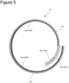
- FIG. 5 is a radial sectional view (a cross section viewed from the axial direction) of proximity of the outermost circumference of the negative electrode 12 (the positive electrode 11 and the separator 13 are omitted). As illustrated in FIG. 5 , the negative electrode mixture layer 42 is absent on the outer circumference side of the negative electrode 12, which is of the outermost circumference, and the negative electrode current collector 40 is exposed.
- FIG. 6 is a radial sectional view (a cross section viewed from the axial direction) of a part of proximity of the outermost circumference of the electrode assembly 14.
- the negative electrode 12 is positioned inside the outer housing can 15, the negative electrode current collector 40 is exposed on the outer circumference side of the negative electrode 12, and this exposed surface of the negative electrode current collector 40 is contacted with the inner face of the outer housing can 15.
- the positive electrode 11 in which the positive electrode mixture layer 32 is formed on both the side of the positive electrode current collector 30 is positioned with the separator 13 interposed therebetween.
- the negative electrode 12 is positioned with the separator 13 interposed therebetween.
- the negative electrode mixture layer 42 (42B) in the one-surface coated portion 46 positioned on the outermost circumference of the electrode assembly 14 has a property different from the negative electrode mixture layer 42 (42A) in the both-surface coated portion on the inner circumference side. That is, in the negative electrode 12 of the non-aqueous electrolyte secondary battery of the present embodiment, the negative electrode mixture layer 42B in the one-surface coated portion 46 has a larger charge expansion coefficient than the negative electrode mixture layer 42A in the both-surface coated portion.
- the charge expansion coefficient of the negative electrode mixture layer 42 (42B) in the one-surface coated portion 46 is set to be larger, and examples of the techniques therefor are as follows.
- Examples of the negative electrode active material having a large charge expansion coefficient include a silicon material including Si and a tin material including Sn.
- the silicon material and the tin material are not essential, but the negative electrode mixture layer 42 (42B) preferably includes the silicon material in the present embodiment.
- Examples of the silicon material include Si, an oxide of Si, and lithium silicate.
- As the oxide of Si a composite in which Si particles are dispersed in a SiO 2 phase may be used, for example.
- the silicon material is preferably used with the carbon material.
- Increasing the charge expansion coefficient of the negative electrode mixture layer 42 (42B) in the one-surface coated portion 46 may allow the exposed surface of the negative electrode current collector 40 on the outermost circumference and the inner face of the outer housing can 15 to be certainly contacted with each other during charge to achieve good current collectability without excessively narrowing the clearance between the electrode assembly 14 and the inner face of the outer housing can 15 during the insertion into outer housing can 15.
- the negative electrode mixture layer 42 contracts with discharge, initial expansion is large compared with contract thereafter. Therefore, an initial charge after the insertion of the electrode assembly 14 may allow the negative electrode current collector 40 on the outermost circumference to be contacted with the inner face of the outer housing can, and may maintain the good electrical contact with charge and discharge also thereafter.
- the entire one-surface coated portion 46 is disposed on the outermost circumference of the electrode assembly 14, but the range where the one-surface coated portion 46 is disposed does not necessarily coincide with the outermost circumference of the electrode assembly 14. As long as at least a part of the one-surface coated portion 46 is disposed on the outermost circumference of the electrode assembly 14, at least a part of the exposed surface of the negative electrode current collector 40 may be sufficiently contacted with the inner face of the outer housing can.
- the one-surface coated portion 46 is preferably disposed within a range of 50% or more of a circumference length of the outermost circumference of the electrode assembly 14. A part of the one-surface coated portion 46 may be disposed so as to extend toward the initial winding side from the outermost circumference of the electrode assembly 14.
- the inner circumference side of the positive electrode mixture layer 32 is required to be opposite to the outer circumference side of the negative electrode mixture layer 42 with the separator 13 interposed therebetween, and thereby the one-surface coated portion 46 is formed from the terminal end part of the negative electrode 12 within a range not to exceed a position opposite to the terminal end of the inner face side of the positive electrode mixture layer 32.
- the range where the negative electrode mixture layer 42 (42B) in the one-surface coated portion 46 is opposed to the positive electrode mixture layer 32 is limited to one round or less, and thereby deterioration due to peeling between the active material and the current collector and due to isolation of the active material may be inhibited even with the increased charge expansion coefficient of the negative electrode mixture layer 42 (42B) in the one-surface coated portion 46.
- This configuration may inhibit the failure during the insertion of the electrode assembly 14 into the outer housing can 15 and deterioration due to the charge-discharge cycles, and may allow the exposed surface of the negative electrode current collector 40 and the inner face of the outer housing can 15 to be certainly contacted with each other to achieve the good current collectability.
- Graphite and an oxide of Si were used as negative electrode active materials.
- Mixing of 94.5 parts by mass of graphite, 5.5 parts by mass of the oxide of Si having an average particle diameter of 5.0 ⁇ m, 1 part by mass of carboxymethylcellulose (CMC), and 1 part by mass of styrene-butadiene rubber (SBR), with water was performed to produce a negative electrode slurry 1. That is, a content of the binder (CMC and SBR) to the negative electrode active material in the negative electrode slurry 1 was 2 mass%.
- the Si proportion and Si particle diameter in the present disclosure mean a proportion and an average particle diameter in the negative electrode active material of the oxide of Si, respectively, and the average particle diameter is a median diameter (D50) on a volumetric basis.
- the oxide of Si in the negative electrode slurry 1 was replaced with one having an average particle diameter of 1 ⁇ m.
- the oxide of Si in the negative electrode slurry 1 was replaced with one having an average particle diameter of 15 ⁇ m.
- the oxide of Si in the negative electrode slurry 1 was replaced with one having an average particle diameter of 20 ⁇ m.
- the negative electrode slurry for a both-surface coated portion and for a one-surface coated portion were applied by using a multilayer die coater with changing the negative electrode slurry depending on a portion to be coated. That is, the negative electrode slurry for the both-surface coated portion was applied on a part to be for the both-surface coated portion, and the negative electrode slurry for the one-surface coated portion was applied on a part to be for one-surface coated portion. Thereafter, the applied film was dried, the dried applied film was rolled, and then cut to a predetermined electrode plate size to produce a negative electrode.
- NMP N-methylpyrrolidone
- LiNi 0.8 Co 0.15 Al 0.05 O 2 as a positive electrode active material
- acetylene black which is a carbon conductive agent
- PVDF polyvinylidene fluoride
- Lead terminals were attached to each of the above positive electrode and the above negative electrode, and the electrodes were wound with a separator interposed therebetween to produce an electrode assembly.
- the one-surface coated portion of the negative electrode was disposed on the outermost circumference of the electrode assembly.
- the wound product was inserted into an outer housing can, which is a battery container, and the negative electrode lead was welded with a bottom of the container.
- the positive electrode lead was ultrasonic-welded with a sealing assembly, the above electrolyte liquid was injected, and the sealing assembly was calked to seal the battery.
- a rated capacity of the produced battery is 2500 mAh.
- the battery was charged at a constant current of 0.5 It until 4.2 V.
- the battery was further charged at a constant voltage of 4.2 V until a current reached 0.05 It.
- the battery was discharged at a constant current of 0.2 It until a voltage reached 2.5 V to measure a discharge capacity.
- Capacity Maintenance Rate (Discharge Capacity at 100th Cycle/Discharge Capacity at 1st Cycle) ⁇ 100
- the slurry 1 was used as the slurry for the both-surface coated portion, and the slurry 2 was used as the slurry for the one-surface coated portion.
- the slurry 1 was used as the slurry for the both-surface coated portion and as the slurry for the one-surface coated portion.
- the slurry 2 was used as the slurry for the both-surface coated portion and as the slurry for the one-surface coated portion.
- the slurry 1 was used as the slurry for the both-surface coated portion, and the slurry 4 was used as the slurry for the one-surface coated portion.
- the slurry 4 was used as the slurry for the both-surface coated portion and as the slurry for the one-surface coated portion.
- the slurry 3 was used as the slurry for the both-surface coated portion, and the slurry 1 was used as the slurry for the one-surface coated portion.
- the slurry 4 was used as the slurry for the both-surface coated portion, and the slurry 5 was used as the slurry for the one-surface coated portion.
- the slurry 1 was used as the slurry for the both-surface coated portion, and the slurry 6 was used as the slurry for the one-surface coated portion.
- the slurry 6 was used as the slurry for the both-surface coated portion and as the slurry for the one-surface coated portion.
- Table 1 shows the DCR and capacity maintenance rate with changing the content proportions of the silicon material (Si proportions) in the negative electrode mixture layer 42A in the both-surface coated portion disposed on the inner circumference side of the outermost circumference and in the negative electrode mixture layer 42B in the one-surface coated portion 46 disposed on the outermost circumference.
- Both-surface coated portion One-surface coated portion DCR Maintenance rate (100cyc) Si proportion Si particle diameter Si proportion Si particle diameter
- Example 1 5.5mass% 5 ⁇ m 20.0mass% 5 ⁇ m 62m ⁇ 92%
- Comparative Example 1 5.5mass% 5 ⁇ m 5.5mass% 5 ⁇ m 105m ⁇ 95%
- Comparative Example 2 20.0mass% 5 ⁇ m 20.0mass% 5 ⁇ m 53m ⁇ 80%
- Table 2 shows the DCR and capacity maintenance rate with changing the average particle diameters of the silicon material (Si particle diameters) in the negative electrode mixture layer 42A in the both-surface coated portion disposed on the inner circumference side of the outermost circumference and in the negative electrode mixture layer 42B in the one-surface coated portion 46 disposed on the outermost circumference.
- Example 2 the DCR is largely reduced compared with Comparative Example 1.
- increasing the Si particle diameter of the one-surface coated portion 46 disposed on the outermost circumference reduces the DCR.
- Example 2 exhibits the capacity maintenance rate similar to that in Comparative Example 1, but in Comparative Example 3, the capacity maintenance rate is lowered compared with Comparative Example 1, although the DCR is largely reduced. That is, setting the Si particle diameter of the one-surface coated portion 46 to be larger than that of the both-surface coated portion can inhibit lowering of the capacity maintenance rate and can reduce the DCR.
- Table 3 shows the DCR and capacity maintenance rate with changing the contents of the binder in the negative electrode mixture layer 42A in the both-surface coated portion disposed on the inner circumference side of the outermost circumference and in the negative electrode mixture layer 42B disposed on the outermost circumference.
- Example 5 the DCR is largely reduced compared with Comparative Example 1.
- increasing the content of the binder in the one-surface coated portion 46 disposed on the outermost circumference reduces the DCR.
- Example 5 exhibits the capacity maintenance rate similar to that in Comparative Example 1, but in Comparative Example 4, the capacity maintenance rate is largely lowered compared with Comparative Example 1, although the DCR is largely reduced. That is, setting the content of the binder in the one-surface coated portion 46 to be larger than that of the both-surface coated portion can inhibit lowering of the capacity maintenance rate and can reduce the DCR.
Landscapes
- Chemical & Material Sciences (AREA)
- Chemical Kinetics & Catalysis (AREA)
- Electrochemistry (AREA)
- General Chemical & Material Sciences (AREA)
- Engineering & Computer Science (AREA)
- Manufacturing & Machinery (AREA)
- Materials Engineering (AREA)
- Secondary Cells (AREA)
Claims (4)
- Sekundärbatterie (10) mit wasserfreiem Elektrolyt, umfassend:eine gewickelte Elektrodenanordnung (14), in der eine bandförmige Positivelektrode (11) und eine bandförmige Negativelektrode (12) mit einem dazwischen angeordneten Separator (13) gewickelt sind; undein äußeres Gehäuserohr (15), das die Elektrodenanordnung (14) unterbringt, wobeidie Positivelektrode (11) eine Positivelektroden-Gemischschicht (32) aufweist, die auf einer Oberfläche eines folienförmigen Positivelektroden-Stromkollektors (30) gebildet ist,die Negativelektrode (12) eine Negativelektroden-Gemischschicht (42) aufweist, die auf einer Oberfläche eines folienförmigen Negativelektroden-Stromkollektors (40) gebildet ist,wobei die Negativelektroden-Gemischschicht (42) ein ladbares und entladbares Negativelektroden-Aktivmaterial und ein Bindemittel umfasst,die Negativelektrode (12) einen auf beiden Oberflächen beschichteten Abschnitt, in dem die Negativelektroden-Gemischschicht (42, 42A) auf beiden Oberflächen des Negativelektroden-Stromkollektors (40) gebildet ist, und einen auf einer Oberfläche beschichteten Abschnitt (46) umfasst, in dem die Negativelektroden-Gemischschicht (42, 42B) auf einer Oberfläche des Negativelektroden-Stromkollektors (40) gebildet ist,mindestens ein Teil des auf einer Oberfläche beschichteten Abschnitts (46) auf einem äußersten Umfang der Elektrodenanordnung (14) angeordnet ist,mindestens ein Teil einer freiliegenden Oberfläche des Negativelektroden-Stromkollektors (40) in dem auf einer Oberfläche beschichteten Abschnitt (46) mit einer Innenseite des äußeren Gehäuserohrs (15) kontaktiert ist, undein Ladungsausdehnungskoeffizient der Negativelektroden-Gemischschicht (42, 42B) in dem auf einer Oberfläche beschichteten Abschnitt (46) größer als ein Ladungsausdehnungskoeffizient der Negativelektroden-Gemischschicht (42, 42A) in dem auf beiden Oberflächen beschichteten Abschnitt ist.
- Sekundärbatterie mit wasserfreiem Elektrolyt nach Anspruch 1, wobei die Negativelektroden-Gemischschicht (42) ein Siliziummaterial als das Negativelektroden-Aktivmaterial umfasst, und ein Anteil des Siliziummaterials an dem Negativelektroden-Aktivmaterial in dem auf einer Oberfläche beschichteten Abschnitt (46) höher als ein Anteil des Siliziummaterials an dem Negativelektroden-Aktivmaterial in dem auf beiden Oberflächen beschichteten Abschnitt ist.
- Sekundärbatterie mit wasserfreiem Elektrolyt nach Anspruch 1 oder 2, wobei die Negativelektroden-Gemischschicht (42) ein Siliziummaterial als das Negativelektroden-Aktivmaterial umfasst, und ein durchschnittlicher Partikeldurchmesser des Siliziummaterials in dem auf einer Oberfläche beschichteten Abschnitt (46) größer als ein durchschnittlicher Partikeldurchmesser des Siliziummaterials in dem auf beiden Oberflächen beschichteten Abschnitt ist.
- Sekundärbatterie mit wasserfreiem Elektrolyt nach einem der Ansprüche 1 bis 3, wobei ein Gehalt des Bindemittels in dem auf einer Oberfläche beschichteten Abschnitt (46) niedriger als ein Gehalt des Bindemittels in dem auf beiden Oberflächen beschichteten Abschnitt ist.
Applications Claiming Priority (2)
| Application Number | Priority Date | Filing Date | Title |
|---|---|---|---|
| JP2020014767 | 2020-01-31 | ||
| PCT/JP2021/002189 WO2021153441A1 (ja) | 2020-01-31 | 2021-01-22 | 非水電解質二次電池 |
Publications (3)
| Publication Number | Publication Date |
|---|---|
| EP4099429A1 EP4099429A1 (de) | 2022-12-07 |
| EP4099429A4 EP4099429A4 (de) | 2024-01-17 |
| EP4099429B1 true EP4099429B1 (de) | 2025-01-08 |
Family
ID=77079776
Family Applications (1)
| Application Number | Title | Priority Date | Filing Date |
|---|---|---|---|
| EP21746969.1A Active EP4099429B1 (de) | 2020-01-31 | 2021-01-22 | Sekundärbatterie mit wasserfreiem elektrolyten |
Country Status (5)
| Country | Link |
|---|---|
| US (1) | US20230073596A1 (de) |
| EP (1) | EP4099429B1 (de) |
| JP (1) | JP7637645B2 (de) |
| CN (1) | CN115210931A (de) |
| WO (1) | WO2021153441A1 (de) |
Families Citing this family (2)
| Publication number | Priority date | Publication date | Assignee | Title |
|---|---|---|---|---|
| CN115039254B (zh) * | 2020-02-05 | 2024-03-12 | 松下新能源株式会社 | 非水电解质二次电池 |
| WO2023133799A1 (zh) * | 2022-01-14 | 2023-07-20 | 宁德时代新能源科技股份有限公司 | 电极组件、电池单体、电池、装置以及制造设备 |
Family Cites Families (12)
| Publication number | Priority date | Publication date | Assignee | Title |
|---|---|---|---|---|
| JP2013254561A (ja) | 2010-09-30 | 2013-12-19 | Panasonic Corp | 円筒形非水電解質二次電池 |
| JP5790241B2 (ja) * | 2011-07-22 | 2015-10-07 | ソニー株式会社 | 非水電解質電池ならびに電池パック、電子機器、電動車両、蓄電装置および電力システム |
| KR101693293B1 (ko) * | 2012-08-20 | 2017-01-05 | 삼성에스디아이 주식회사 | 리튬 이차 전지용 음극 활물질, 이를 포함하는 음극 및 리튬 이차 전지 |
| JP2015053129A (ja) * | 2013-09-05 | 2015-03-19 | 日立オートモティブシステムズ株式会社 | 角形二次電池 |
| US20160156031A1 (en) * | 2014-11-28 | 2016-06-02 | Samsung Electronics Co., Ltd. | Anode active material for lithium secondary battery and lithium secondary battery including the anode active material |
| JPWO2017038041A1 (ja) * | 2015-08-28 | 2018-06-14 | パナソニックIpマネジメント株式会社 | 非水電解質二次電池 |
| WO2017122251A1 (ja) * | 2016-01-12 | 2017-07-20 | 三洋電機株式会社 | 非水電解質二次電池 |
| WO2018056107A1 (ja) * | 2016-09-23 | 2018-03-29 | パナソニックIpマネジメント株式会社 | 非水電解質二次電池用負極、非水電解質二次電池及び非水電解質二次電池用負極の製造方法 |
| US20210159545A1 (en) * | 2017-03-16 | 2021-05-27 | Sanyo Electric Co., Ltd. | Non-aqueous electrolyte secondary battery |
| EP3780241A4 (de) * | 2018-03-27 | 2021-05-19 | Sanyo Electric Co., Ltd. | Sekundärbatterie mit wasserfreiem elektrolyt |
| JP7386432B2 (ja) * | 2018-05-30 | 2023-11-27 | パナソニックIpマネジメント株式会社 | 非水電解質二次電池 |
| US12095074B2 (en) * | 2018-06-28 | 2024-09-17 | Panasonic Energy Co., Ltd. | Nonaqueous electrolyte secondary battery |
-
2021
- 2021-01-22 WO PCT/JP2021/002189 patent/WO2021153441A1/ja not_active Ceased
- 2021-01-22 EP EP21746969.1A patent/EP4099429B1/de active Active
- 2021-01-22 CN CN202180010579.8A patent/CN115210931A/zh active Pending
- 2021-01-22 US US17/795,109 patent/US20230073596A1/en active Pending
- 2021-01-22 JP JP2021573988A patent/JP7637645B2/ja active Active
Also Published As
| Publication number | Publication date |
|---|---|
| EP4099429A4 (de) | 2024-01-17 |
| US20230073596A1 (en) | 2023-03-09 |
| CN115210931A (zh) | 2022-10-18 |
| JPWO2021153441A1 (de) | 2021-08-05 |
| WO2021153441A1 (ja) | 2021-08-05 |
| JP7637645B2 (ja) | 2025-02-28 |
| EP4099429A1 (de) | 2022-12-07 |
Similar Documents
| Publication | Publication Date | Title |
|---|---|---|
| EP3723163B1 (de) | Sekundärbatterie, isolierelement und positive elektrodenleitung | |
| EP3813178A1 (de) | Sekundärbatterie mit wasserfreiem elektrolyt | |
| CN110224181B (zh) | 非水电解质二次电池及其制造方法 | |
| EP4191697A1 (de) | Sekundärbatterie mit nichtwässrigem elektrolyten | |
| EP4471927A1 (de) | Zylindrische sekundärbatterie mit nichtwässrigem elektrolyten | |
| EP4443594A1 (de) | Sekundärbatterie mit nichtwässrigem elektrolyten | |
| EP4318702A1 (de) | Zylindrische batterie | |
| EP4099429B1 (de) | Sekundärbatterie mit wasserfreiem elektrolyten | |
| US20200280027A1 (en) | Cylindrical nonaqueous electrolyte secondary battery | |
| EP4489211A1 (de) | Zylindrische sekundärbatterie mit nichtwässrigem elektrolyten | |
| US20240387966A1 (en) | Cylindrical battery | |
| EP4398372A1 (de) | Sekundärbatterie mit nichtwässrigem elektrolyten | |
| EP3876332A1 (de) | Sekundärbatterie | |
| EP4350798A1 (de) | Sekundärbatterie mit nichtwässrigem elektrolyten | |
| JP2000036324A (ja) | 非水二次電池 | |
| EP4024555A1 (de) | Sekundärbatterie mit wasserfreiem elektrolyt sowie herstellungsverfahren für die sekundärbatterie mit wasserfreiem elektrolyt | |
| US20230079288A1 (en) | Nonaqueous electrolyte secondary battery and electrode for nonaqueous electrolyte secondary batteries | |
| EP4471885A1 (de) | Sekundärbatterie mit nichtwässrigem elektrolyten | |
| JP4069988B2 (ja) | リチウムイオン二次電池 | |
| EP4398332B1 (de) | Negativelektrode für sekundärbatterie und sekundärbatterie | |
| EP4333153A1 (de) | Sekundärbatterie mit nichtwässrigem elektrolyten | |
| EP3940838A1 (de) | Sekundärbatterie mit wasserfreiem elektrolyt sowie verfahren zur herstellung der sekundärbatterie mit wasserfreiem elektrolyt | |
| JPH11329443A (ja) | リチウム二次電池 | |
| US20230080854A1 (en) | Non-aqueous electrolyte secondary battery | |
| EP4489174A1 (de) | Zylindrische sekundärbatterie mit nichtwässrigem elektrolyten |
Legal Events
| Date | Code | Title | Description |
|---|---|---|---|
| STAA | Information on the status of an ep patent application or granted ep patent |
Free format text: STATUS: THE INTERNATIONAL PUBLICATION HAS BEEN MADE |
|
| PUAI | Public reference made under article 153(3) epc to a published international application that has entered the european phase |
Free format text: ORIGINAL CODE: 0009012 |
|
| STAA | Information on the status of an ep patent application or granted ep patent |
Free format text: STATUS: REQUEST FOR EXAMINATION WAS MADE |
|
| 17P | Request for examination filed |
Effective date: 20220725 |
|
| AK | Designated contracting states |
Kind code of ref document: A1 Designated state(s): AL AT BE BG CH CY CZ DE DK EE ES FI FR GB GR HR HU IE IS IT LI LT LU LV MC MK MT NL NO PL PT RO RS SE SI SK SM TR |
|
| DAV | Request for validation of the european patent (deleted) | ||
| DAX | Request for extension of the european patent (deleted) | ||
| A4 | Supplementary search report drawn up and despatched |
Effective date: 20231218 |
|
| RIC1 | Information provided on ipc code assigned before grant |
Ipc: H01M 4/02 20060101ALN20231213BHEP Ipc: H01M 4/38 20060101ALI20231213BHEP Ipc: H01M 4/134 20100101ALI20231213BHEP Ipc: H01M 10/0525 20100101ALI20231213BHEP Ipc: H01M 10/04 20060101ALI20231213BHEP Ipc: H01M 4/62 20060101ALI20231213BHEP Ipc: H01M 10/0587 20100101ALI20231213BHEP Ipc: H01M 4/13 20100101AFI20231213BHEP |
|
| GRAP | Despatch of communication of intention to grant a patent |
Free format text: ORIGINAL CODE: EPIDOSNIGR1 |
|
| STAA | Information on the status of an ep patent application or granted ep patent |
Free format text: STATUS: GRANT OF PATENT IS INTENDED |
|
| RIC1 | Information provided on ipc code assigned before grant |
Ipc: H01M 4/02 20060101ALN20240705BHEP Ipc: H01M 4/38 20060101ALI20240705BHEP Ipc: H01M 4/134 20100101ALI20240705BHEP Ipc: H01M 10/0525 20100101ALI20240705BHEP Ipc: H01M 10/04 20060101ALI20240705BHEP Ipc: H01M 4/62 20060101ALI20240705BHEP Ipc: H01M 10/0587 20100101ALI20240705BHEP Ipc: H01M 4/13 20100101AFI20240705BHEP |
|
| RIC1 | Information provided on ipc code assigned before grant |
Ipc: H01M 4/02 20060101ALN20240715BHEP Ipc: H01M 4/38 20060101ALI20240715BHEP Ipc: H01M 4/134 20100101ALI20240715BHEP Ipc: H01M 10/0525 20100101ALI20240715BHEP Ipc: H01M 10/04 20060101ALI20240715BHEP Ipc: H01M 4/62 20060101ALI20240715BHEP Ipc: H01M 10/0587 20100101ALI20240715BHEP Ipc: H01M 4/13 20100101AFI20240715BHEP |
|
| INTG | Intention to grant announced |
Effective date: 20240729 |
|
| RIN1 | Information on inventor provided before grant (corrected) |
Inventor name: MORIKAWA, TAKAHARU Inventor name: SAKITANI, NOBUHIRO |
|
| P01 | Opt-out of the competence of the unified patent court (upc) registered |
Free format text: CASE NUMBER: APP_50841/2024 Effective date: 20240909 |
|
| GRAS | Grant fee paid |
Free format text: ORIGINAL CODE: EPIDOSNIGR3 |
|
| RAP3 | Party data changed (applicant data changed or rights of an application transferred) |
Owner name: SANYO ELECTRIC CO., LTD. |
|
| GRAA | (expected) grant |
Free format text: ORIGINAL CODE: 0009210 |
|
| STAA | Information on the status of an ep patent application or granted ep patent |
Free format text: STATUS: THE PATENT HAS BEEN GRANTED |
|
| RAP1 | Party data changed (applicant data changed or rights of an application transferred) |
Owner name: PANASONIC ENERGY CO., LTD. |
|
| AK | Designated contracting states |
Kind code of ref document: B1 Designated state(s): AL AT BE BG CH CY CZ DE DK EE ES FI FR GB GR HR HU IE IS IT LI LT LU LV MC MK MT NL NO PL PT RO RS SE SI SK SM TR |
|
| REG | Reference to a national code |
Ref country code: GB Ref legal event code: FG4D |
|
| REG | Reference to a national code |
Ref country code: CH Ref legal event code: EP |
|
| REG | Reference to a national code |
Ref country code: DE Ref legal event code: R096 Ref document number: 602021024695 Country of ref document: DE |
|
| REG | Reference to a national code |
Ref country code: IE Ref legal event code: FG4D |
|
| REG | Reference to a national code |
Ref country code: SE Ref legal event code: TRGR |
|
| PGFP | Annual fee paid to national office [announced via postgrant information from national office to epo] |
Ref country code: DE Payment date: 20250228 Year of fee payment: 5 |
|
| PGFP | Annual fee paid to national office [announced via postgrant information from national office to epo] |
Ref country code: SE Payment date: 20250227 Year of fee payment: 5 |
|
| PGFP | Annual fee paid to national office [announced via postgrant information from national office to epo] |
Ref country code: NO Payment date: 20250325 Year of fee payment: 5 |
|
| PGFP | Annual fee paid to national office [announced via postgrant information from national office to epo] |
Ref country code: AT Payment date: 20250417 Year of fee payment: 5 |
|
| PGFP | Annual fee paid to national office [announced via postgrant information from national office to epo] |
Ref country code: FR Payment date: 20250228 Year of fee payment: 5 |
|
| PGFP | Annual fee paid to national office [announced via postgrant information from national office to epo] |
Ref country code: GB Payment date: 20250227 Year of fee payment: 5 |
|
| REG | Reference to a national code |
Ref country code: LT Ref legal event code: MG9D |
|
| REG | Reference to a national code |
Ref country code: NL Ref legal event code: MP Effective date: 20250108 |
|
| REG | Reference to a national code |
Ref country code: AT Ref legal event code: MK05 Ref document number: 1758926 Country of ref document: AT Kind code of ref document: T Effective date: 20250108 |
|
| PG25 | Lapsed in a contracting state [announced via postgrant information from national office to epo] |
Ref country code: NL Free format text: LAPSE BECAUSE OF FAILURE TO SUBMIT A TRANSLATION OF THE DESCRIPTION OR TO PAY THE FEE WITHIN THE PRESCRIBED TIME-LIMIT Effective date: 20250108 |
|
| PG25 | Lapsed in a contracting state [announced via postgrant information from national office to epo] |
Ref country code: RS Free format text: LAPSE BECAUSE OF FAILURE TO SUBMIT A TRANSLATION OF THE DESCRIPTION OR TO PAY THE FEE WITHIN THE PRESCRIBED TIME-LIMIT Effective date: 20250408 |
|
| PG25 | Lapsed in a contracting state [announced via postgrant information from national office to epo] |
Ref country code: FI Free format text: LAPSE BECAUSE OF FAILURE TO SUBMIT A TRANSLATION OF THE DESCRIPTION OR TO PAY THE FEE WITHIN THE PRESCRIBED TIME-LIMIT Effective date: 20250108 |
|
| PG25 | Lapsed in a contracting state [announced via postgrant information from national office to epo] |
Ref country code: PL Free format text: LAPSE BECAUSE OF FAILURE TO SUBMIT A TRANSLATION OF THE DESCRIPTION OR TO PAY THE FEE WITHIN THE PRESCRIBED TIME-LIMIT Effective date: 20250108 |
|
| PG25 | Lapsed in a contracting state [announced via postgrant information from national office to epo] |
Ref country code: ES Free format text: LAPSE BECAUSE OF FAILURE TO SUBMIT A TRANSLATION OF THE DESCRIPTION OR TO PAY THE FEE WITHIN THE PRESCRIBED TIME-LIMIT Effective date: 20250108 |
|
| PG25 | Lapsed in a contracting state [announced via postgrant information from national office to epo] |
Ref country code: IS Free format text: LAPSE BECAUSE OF FAILURE TO SUBMIT A TRANSLATION OF THE DESCRIPTION OR TO PAY THE FEE WITHIN THE PRESCRIBED TIME-LIMIT Effective date: 20250508 |
|
| PG25 | Lapsed in a contracting state [announced via postgrant information from national office to epo] |
Ref country code: HR Free format text: LAPSE BECAUSE OF FAILURE TO SUBMIT A TRANSLATION OF THE DESCRIPTION OR TO PAY THE FEE WITHIN THE PRESCRIBED TIME-LIMIT Effective date: 20250108 |
|
| PG25 | Lapsed in a contracting state [announced via postgrant information from national office to epo] |
Ref country code: PT Free format text: LAPSE BECAUSE OF FAILURE TO SUBMIT A TRANSLATION OF THE DESCRIPTION OR TO PAY THE FEE WITHIN THE PRESCRIBED TIME-LIMIT Effective date: 20250508 Ref country code: LV Free format text: LAPSE BECAUSE OF FAILURE TO SUBMIT A TRANSLATION OF THE DESCRIPTION OR TO PAY THE FEE WITHIN THE PRESCRIBED TIME-LIMIT Effective date: 20250108 |
|
| PG25 | Lapsed in a contracting state [announced via postgrant information from national office to epo] |
Ref country code: GR Free format text: LAPSE BECAUSE OF FAILURE TO SUBMIT A TRANSLATION OF THE DESCRIPTION OR TO PAY THE FEE WITHIN THE PRESCRIBED TIME-LIMIT Effective date: 20250409 Ref country code: BG Free format text: LAPSE BECAUSE OF FAILURE TO SUBMIT A TRANSLATION OF THE DESCRIPTION OR TO PAY THE FEE WITHIN THE PRESCRIBED TIME-LIMIT Effective date: 20250108 |
|
| PG25 | Lapsed in a contracting state [announced via postgrant information from national office to epo] |
Ref country code: AT Free format text: LAPSE BECAUSE OF FAILURE TO SUBMIT A TRANSLATION OF THE DESCRIPTION OR TO PAY THE FEE WITHIN THE PRESCRIBED TIME-LIMIT Effective date: 20250108 |
|
| REG | Reference to a national code |
Ref country code: CH Ref legal event code: PL |
|
| PG25 | Lapsed in a contracting state [announced via postgrant information from national office to epo] |
Ref country code: LU Free format text: LAPSE BECAUSE OF NON-PAYMENT OF DUE FEES Effective date: 20250122 |
|
| PG25 | Lapsed in a contracting state [announced via postgrant information from national office to epo] |
Ref country code: SM Free format text: LAPSE BECAUSE OF FAILURE TO SUBMIT A TRANSLATION OF THE DESCRIPTION OR TO PAY THE FEE WITHIN THE PRESCRIBED TIME-LIMIT Effective date: 20250108 |
|
| REG | Reference to a national code |
Ref country code: DE Ref legal event code: R097 Ref document number: 602021024695 Country of ref document: DE |
|
| PG25 | Lapsed in a contracting state [announced via postgrant information from national office to epo] |
Ref country code: DK Free format text: LAPSE BECAUSE OF FAILURE TO SUBMIT A TRANSLATION OF THE DESCRIPTION OR TO PAY THE FEE WITHIN THE PRESCRIBED TIME-LIMIT Effective date: 20250108 |
|
| PG25 | Lapsed in a contracting state [announced via postgrant information from national office to epo] |
Ref country code: MC Free format text: LAPSE BECAUSE OF FAILURE TO SUBMIT A TRANSLATION OF THE DESCRIPTION OR TO PAY THE FEE WITHIN THE PRESCRIBED TIME-LIMIT Effective date: 20250108 |
|
| PG25 | Lapsed in a contracting state [announced via postgrant information from national office to epo] |
Ref country code: BE Free format text: LAPSE BECAUSE OF NON-PAYMENT OF DUE FEES Effective date: 20250131 |
|
| PG25 | Lapsed in a contracting state [announced via postgrant information from national office to epo] |
Ref country code: CH Free format text: LAPSE BECAUSE OF NON-PAYMENT OF DUE FEES Effective date: 20250131 |
|
| PG25 | Lapsed in a contracting state [announced via postgrant information from national office to epo] |
Ref country code: CZ Free format text: LAPSE BECAUSE OF FAILURE TO SUBMIT A TRANSLATION OF THE DESCRIPTION OR TO PAY THE FEE WITHIN THE PRESCRIBED TIME-LIMIT Effective date: 20250108 Ref country code: EE Free format text: LAPSE BECAUSE OF FAILURE TO SUBMIT A TRANSLATION OF THE DESCRIPTION OR TO PAY THE FEE WITHIN THE PRESCRIBED TIME-LIMIT Effective date: 20250108 |
|
| REG | Reference to a national code |
Ref country code: BE Ref legal event code: MM Effective date: 20250131 |
|
| PG25 | Lapsed in a contracting state [announced via postgrant information from national office to epo] |
Ref country code: RO Free format text: LAPSE BECAUSE OF FAILURE TO SUBMIT A TRANSLATION OF THE DESCRIPTION OR TO PAY THE FEE WITHIN THE PRESCRIBED TIME-LIMIT Effective date: 20250108 |
|
| PG25 | Lapsed in a contracting state [announced via postgrant information from national office to epo] |
Ref country code: SK Free format text: LAPSE BECAUSE OF FAILURE TO SUBMIT A TRANSLATION OF THE DESCRIPTION OR TO PAY THE FEE WITHIN THE PRESCRIBED TIME-LIMIT Effective date: 20250108 |
|
| PLBE | No opposition filed within time limit |
Free format text: ORIGINAL CODE: 0009261 |
|
| STAA | Information on the status of an ep patent application or granted ep patent |
Free format text: STATUS: NO OPPOSITION FILED WITHIN TIME LIMIT |
|
| 26N | No opposition filed |
Effective date: 20251009 |
|
| PG25 | Lapsed in a contracting state [announced via postgrant information from national office to epo] |
Ref country code: IE Free format text: LAPSE BECAUSE OF NON-PAYMENT OF DUE FEES Effective date: 20250122 |
|
| PG25 | Lapsed in a contracting state [announced via postgrant information from national office to epo] |
Ref country code: IT Free format text: LAPSE BECAUSE OF FAILURE TO SUBMIT A TRANSLATION OF THE DESCRIPTION OR TO PAY THE FEE WITHIN THE PRESCRIBED TIME-LIMIT Effective date: 20250108 |