EP4099069A2 - Glasfaserverbinderanordnung - Google Patents
Glasfaserverbinderanordnung Download PDFInfo
- Publication number
- EP4099069A2 EP4099069A2 EP22176000.2A EP22176000A EP4099069A2 EP 4099069 A2 EP4099069 A2 EP 4099069A2 EP 22176000 A EP22176000 A EP 22176000A EP 4099069 A2 EP4099069 A2 EP 4099069A2
- Authority
- EP
- European Patent Office
- Prior art keywords
- housing
- optic fiber
- connector assembly
- structure body
- fiber connector
- Prior art date
- Legal status (The legal status is an assumption and is not a legal conclusion. Google has not performed a legal analysis and makes no representation as to the accuracy of the status listed.)
- Pending
Links
Images


Classifications
-
- G—PHYSICS
- G02—OPTICS
- G02B—OPTICAL ELEMENTS, SYSTEMS OR APPARATUS
- G02B6/00—Light guides; Structural details of arrangements comprising light guides and other optical elements, e.g. couplings
- G02B6/24—Coupling light guides
- G02B6/36—Mechanical coupling means
- G02B6/38—Mechanical coupling means having fibre to fibre mating means
- G02B6/3807—Dismountable connectors, i.e. comprising plugs
- G02B6/389—Dismountable connectors, i.e. comprising plugs characterised by the method of fastening connecting plugs and sockets, e.g. screw- or nut-lock, snap-in, bayonet type
- G02B6/3893—Push-pull type, e.g. snap-in, push-on
-
- G—PHYSICS
- G02—OPTICS
- G02B—OPTICAL ELEMENTS, SYSTEMS OR APPARATUS
- G02B6/00—Light guides; Structural details of arrangements comprising light guides and other optical elements, e.g. couplings
- G02B6/24—Coupling light guides
- G02B6/36—Mechanical coupling means
- G02B6/38—Mechanical coupling means having fibre to fibre mating means
- G02B6/3807—Dismountable connectors, i.e. comprising plugs
- G02B6/381—Dismountable connectors, i.e. comprising plugs of the ferrule type, e.g. fibre ends embedded in ferrules, connecting a pair of fibres
- G02B6/3818—Dismountable connectors, i.e. comprising plugs of the ferrule type, e.g. fibre ends embedded in ferrules, connecting a pair of fibres of a low-reflection-loss type
- G02B6/3821—Dismountable connectors, i.e. comprising plugs of the ferrule type, e.g. fibre ends embedded in ferrules, connecting a pair of fibres of a low-reflection-loss type with axial spring biasing or loading means
-
- G—PHYSICS
- G02—OPTICS
- G02B—OPTICAL ELEMENTS, SYSTEMS OR APPARATUS
- G02B6/00—Light guides; Structural details of arrangements comprising light guides and other optical elements, e.g. couplings
- G02B6/24—Coupling light guides
- G02B6/36—Mechanical coupling means
- G02B6/38—Mechanical coupling means having fibre to fibre mating means
- G02B6/3807—Dismountable connectors, i.e. comprising plugs
- G02B6/381—Dismountable connectors, i.e. comprising plugs of the ferrule type, e.g. fibre ends embedded in ferrules, connecting a pair of fibres
- G02B6/3825—Dismountable connectors, i.e. comprising plugs of the ferrule type, e.g. fibre ends embedded in ferrules, connecting a pair of fibres with an intermediate part, e.g. adapter, receptacle, linking two plugs
-
- G—PHYSICS
- G02—OPTICS
- G02B—OPTICAL ELEMENTS, SYSTEMS OR APPARATUS
- G02B6/00—Light guides; Structural details of arrangements comprising light guides and other optical elements, e.g. couplings
- G02B6/24—Coupling light guides
- G02B6/36—Mechanical coupling means
- G02B6/38—Mechanical coupling means having fibre to fibre mating means
- G02B6/3807—Dismountable connectors, i.e. comprising plugs
- G02B6/3869—Mounting ferrules to connector body, i.e. plugs
-
- G—PHYSICS
- G02—OPTICS
- G02B—OPTICAL ELEMENTS, SYSTEMS OR APPARATUS
- G02B6/00—Light guides; Structural details of arrangements comprising light guides and other optical elements, e.g. couplings
- G02B6/24—Coupling light guides
- G02B6/36—Mechanical coupling means
- G02B6/38—Mechanical coupling means having fibre to fibre mating means
- G02B6/3807—Dismountable connectors, i.e. comprising plugs
- G02B6/3873—Connectors using guide surfaces for aligning ferrule ends, e.g. tubes, sleeves, V-grooves, rods, pins, balls
- G02B6/3874—Connectors using guide surfaces for aligning ferrule ends, e.g. tubes, sleeves, V-grooves, rods, pins, balls using tubes, sleeves to align ferrules
- G02B6/3878—Connectors using guide surfaces for aligning ferrule ends, e.g. tubes, sleeves, V-grooves, rods, pins, balls using tubes, sleeves to align ferrules comprising a plurality of ferrules, branching and break-out means
-
- G—PHYSICS
- G02—OPTICS
- G02B—OPTICAL ELEMENTS, SYSTEMS OR APPARATUS
- G02B6/00—Light guides; Structural details of arrangements comprising light guides and other optical elements, e.g. couplings
- G02B6/24—Coupling light guides
- G02B6/36—Mechanical coupling means
- G02B6/38—Mechanical coupling means having fibre to fibre mating means
- G02B6/3807—Dismountable connectors, i.e. comprising plugs
- G02B6/3873—Connectors using guide surfaces for aligning ferrule ends, e.g. tubes, sleeves, V-grooves, rods, pins, balls
- G02B6/3874—Connectors using guide surfaces for aligning ferrule ends, e.g. tubes, sleeves, V-grooves, rods, pins, balls using tubes, sleeves to align ferrules
Definitions
- the disclosure relates to a connector assembly, and in particular relates to an optic fiber connector assembly.
- optic fiber Due to the advantages of high bandwidth and low loss, optic fiber has been widely used as a signal transmission medium in recent years. Therefore, with the expansion of optical communication network technology, wide area networks such as the internet and the intranet have become popular, and at the same time, communication flow has been improved.
- a typical optic fiber connector is composed of a matching female adapter and male optic fiber connector.
- the female adapter is disposed in the electronic device, and the male optic fiber connector is plugged into the female adapter to establish a connection, so as to achieve the purpose of locking and data transmission at the same time.
- the current situation is that, with the development of technology, due to a relatively large structural size and high spacing ratio, these products often cannot effectively reduce the optical path spacing, and cannot meet the requirements of 5G communication for wiring density.
- the disclosure provides an optic fiber connector assembly, and an adapter and a connector of the optic fiber connector assembly are adapted to each other through the structural outline to achieve the effect of mutual fixation.
- the optic fiber connector assembly of the disclosure includes at least one adapter and at least one connector.
- the adapter is correspondingly connected to the at least one connector.
- the adapter includes a first housing, at least one sleeve, at least one bridging portion, and at least one locking arm.
- the sleeve is disposed in the first housing.
- the bridging portion extends out of a side of the first housing, the sleeve extends from an inside of the first housing to the corresponding bridging portion, and the locking arm extends from the side and is located next to the bridging portion.
- the connector includes a second housing, a ferrule, and a spring.
- the ferrule is disposed in the second housing in a penetrating manner, and the spring is abutted between the second housing and the ferrule.
- the second housing is sleeved onto the bridging portion, the ferrule is inserted into the sleeve, and the locking arm is buckled onto the second housing.
- An inner wall of the second housing and an outer wall of the bridging portion are polygonally adapted to each other for mutual fixation, preventing the connector and the adapter from rotating relative to each other along the axis.
- the ferrule is divided into an A portion, a B portion, and a C portion along the axis.
- the A portion is configured to accommodate an optic fiber core and is inserted into the sleeve
- the B portion is located between the A portion and the C portion
- the B portion is locked onto an accommodating groove in the second housing
- the C portion extends from the B portion and is located in the accommodating groove
- the spring is sleeved onto the C portion and is abutted between the B portion and the accommodating groove.
- the ferrule further has a D portion and an E portion.
- the D portion is connected between the A portion and the B portion and the D portion is configured to abut the bridging portion, and the C portion is connected between the B portion and the E portion.
- the second housing also has a lip portion located outside the accommodating groove, and the E portion is located outside the second housing and is locked onto the lip portion.
- the ferrule includes a first structure body and a second structure body.
- the second structure body is sleeved onto a portion of the first structure body.
- the first structure body has the A portion
- the second structure body has the B portion, the C portion, the D portion, and the E portion.
- an elastic force applied by the spring to the B portion is offset by locking the E portion onto the lip portion.
- the B portion and the accommodating groove are polygonally adapted to each other for mutual fixation, preventing the ferrule and the second housing from rotating relative to each other along the axis.
- the second housing forms an elastic arm structure outside the accommodating groove, and the second housing also has a locking step located on the elastic arm structure.
- the locking arm is suitable for buckling onto the locking step.
- the adapter further includes at least one partitioning member, and multiple sleeves and multiple bridging portions corresponding to each other.
- the partitioning member is detachably assembled in the first housing, so that there is one partitioning member between any adjacent two of the sleeves.
- the partitioning member is a T-shaped structure body
- a clamping tube extends from each of a pair of wing portions of the T-shaped structure body, and the pair of clamping tubes respectively correspond to adjacent two of the bridging portions, so that the sleeve is accommodated in the bridging portion and the clamping tube corresponding to each other.
- the partitioning member is a T-shaped structure body
- a partitioning plate of the T-shaped structure body has at least one first rib and at least one first protrusion
- the first housing has at least one first guide groove and at least one opening.
- the T-shaped structure body is moved into the first housing by matching the first rib and the first guide groove, and the T-shaped structure body is fixed in the first housing by snapping the first protrusion onto the opening B.
- the optic fiber connector assembly includes multiple adapters.
- one of the adapters includes at least one second rib disposed on a side wall of the first housing, and other one of the adapters includes at least one second guide groove disposed on another side wall of the first housing. By matching the second rib and the second guide groove, any adjacent two of the adapters are combined together.
- one of the adapters also has a second protrusion located on the side wall, and other one of the adapters also has a slot located on the another side wall.
- the second protrusion is snapped onto the slot, so that the adjacent two of the adapters are fixed together.
- the optic fiber connector assembly is composed of the adapter and the connector.
- the adapter is suitable for correspondingly connecting at least one connector, that is, multiple connectors can be docked and integrated into the same adapter with the structure illustrated below, and in order to facilitate the fixation effect of the optic fiber core wire, the bridging portion of the adapter and the ferrule of the connector refer to an outline that adapts to each other, so that the inner wall of the second housing of the connector and the outer wall of the bridging portion of the adapter are docked together in a polygonally adapted structure, thereby achieving the required effect of mutual fixation and also preventing the connector and the adapter from rotating relative to each other.
- FIG. 1 is a schematic view of an optic fiber connector assembly according to an embodiment of the disclosure.
- FIG. 2 is a schematic view of an assembly of the optic fiber connector assembly of FIG. 1 .
- an optic fiber connector assembly 10 of the disclosure includes at least one adapter 200 and at least one connector 100, wherein the adapter 200 is correspondingly connected to at least one connector 100.
- the multiple combined adapters 200 and connectors 100 shown here it is exemplified that one adapter 200 is correspondingly connected to two connectors 100.
- FIG. 3 is an exploded view of a connector.
- the connector 100 includes a second housing 110, a ferrule 120, and a spring 130.
- the ferrule 120 is disposed in the second housing 110 in a penetrating manner, and the spring 130 is abutted between the second housing 110 and the ferrule 120.
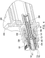
- FIG. 4 is a partial cross-sectional view of a optic fiber connector assembly.
- FIG. 5 is an exploded view of an adapter. Referring to FIG. 3 to FIG.
- the adapter 200 of the embodiment includes a first housing 210, at least one sleeve 250 (two sleeves 250 are illustrated herein as an example), at least one bridging portion 240 (two bridging portions 240 are illustrated herein as an example), and at least one locking arm 230 (each of the bridging portions 240 adjoining a pair of the locking arms 230 are illustrated herein as an example).
- the sleeves 250 are disposed in the first housing 210.
- the bridging portion 240 extends from one side of the first housing 210
- the sleeve 250 extends from the first housing 210 to the corresponding bridging portion 240
- the locking arms 230 extend from the side and are located next to the bridging portion 240, that is, the locking arms 230 are on the same side as the bridging portion 240.
- the second housings 110 are sleeved onto the bridging portions 240, the ferrules 120 are inserted into the sleeves 250, and the locking arms 230 are buckled onto the second housings 110.
- An inner wall of the second housing 110 and an outer wall of the bridging portion 240 are polygonally (shown as a quadrilateral in the embodiment) adapted to each other for mutual fixation, preventing the connector 100 and the adapter 200 from rotating relative to each other along the axis and affecting the fixation effect of the optic fiber core wire.
- the ferrule 120 of the embodiment is divided into an A portion 121, a B portion 123, and a C portion 124 along the axis.
- the A portion 121 is configured to accommodate the optic fiber core and is inserted into the ferrule 250
- the B portion 123 is located between the A portion 121 and the C portion 124
- the B portion 123 is locked onto an accommodating groove 111 in the second housing 110
- the C portion 124 extends from the B portion 123 and is located in the accommodating groove 111
- the spring 130 is sleeved onto the C portion 124 and is abutted between the B portion 123 and the accommodating groove 111.
- the B portion 123 and the accommodating groove 111 are polygonally (shown as a quadrilateral in the embodiment) adapted to each other for mutual fixation, preventing the ferrules 120 and the second housings 110 from rotating relative to each other along the axis.
- the reason for adopting a quadrilateral adapting outline is that in order to prevent rotation relative to each other along the axis, the quadrilateral adapting outline is a preferred embodiment of the disclosure because the required torque is the maximum.
- the ferrule 120 of the embodiment also has a D portion 122 and an E portion 125.
- the D portion 122 is connected between the A portion 121 and the B portion 123 and the D portion is configured to abut the bridging portion 240, the C portion 124 is connected between the B portion 123 and the E portion 125.
- the second housing 110 also has lip portions 112 located outside the accommodating groove 111, and the E portion 125 penetrates out of the second housing 110 and is locked onto the lip portions 112. It can be clearly seen from FIG. 4 that the spring 130 located in the accommodating groove 111 exerts a rightward elastic force on the ferrule 120 as shown in FIG.
- the spring 130 exerts a rightward elastic force on the B portion 123.
- the rightward elastic force can be stopped and offset, so that the ferrule 120 and the spring 130 can be stably disposed in the second housing 110.
- the outer diameter of the outline of the E portion 125 is larger than that of the C portion 124, the E portion 125 can be smoothly locked onto the outside of the second housing 110.
- the ferrule 120 of the embodiment includes a first structure body and a second structure body, wherein the second structure body is sleeved onto a portion of the first structure body.
- the first structure body has an A portion 121
- the second structure body has a B portion 123, a C portion 124, a D portion 122, and an E portion 125.
- the second housing 110 is formed with upper and lower elastic arm structures outside the accommodating groove 111, and the second housing 110 also has a locking step 113 located on the elastic arm structure, so that when the connector 100 and the adapter 200 are correspondingly connected, the locking arm 230 of the adapter 200 can be buckled onto the locking step 113, and once the user wants to separate the connector 100 from the adapter 200, the locking step 113 can be withdrawn from the locking arm 230 by pressing with force against the elastic arm structure.
- the adapter 200 of the embodiment further includes a longitudinal plate 220 and at least one partitioning member 260.
- the first housing 210 is located on one side of the longitudinal plate 220, and the bridging portions 240 and the locking arms 230 are located on the other side of the longitudinal plate 220.
- the partitioning member 260 is configured to separate multiple sleeves 250 that correspond to each other. That is, the partitioning member 260 is detachably assembled in the first housing 210, so that there can be a partitioning member 260 between two adjacent sleeves 250.
- the partitioning member 260 of the embodiment is a T-shaped structure body, which includes a partitioning plate 261 and a pair of wing portions 266 located on opposite sides of the partitioning plate 261, wherein the partitioning plate 261 has first ribs 263 and 265 and a first protrusion 264, and the first housing 210 has first guide grooves 213 and 214 and openings 211 and 212.
- the T-shaped structure body is moved into the first housing 210 by matching the first ribs 263 and 265 and the first guide grooves 213 and 214, and the T-shaped structure body is fixed in the first housing 210 by snapping the first protrusion 264 onto the openings 211 and 212.
- the partitioning member 260 also has a pair of clamping tubes 262 extending from the wing portions 266, corresponding to the bridging portions 240 respectively, so that the sleeves 250 can be stably accommodated and fixed on the clamping tubes 262 and the bridging portions 240 of the adapter 200.
- FIG. 6 is a schematic view of a combination of multiple adapters.
- one of the adapters 200 in two adjacent adapters 200, one of the adapters 200 includes second ribs 215 disposed on the side wall of the first housing 210, and the other adapter 200 includes second guide grooves 217 disposed on the side wall of the first housing 210.
- second ribs 215 and the second guide grooves 217 By matching the second ribs 215 and the second guide grooves 217, two adjacent adapters 200 can be guided and slidably connected together.
- one of the adapters 200 also has a second protrusion 216 located on the side wall, and the other adapter 200 also has a slot 218 located on the side wall, so as to provide a stopping and locking mechanism for the above-mentioned guiding and slidable connection process, that is, the second protrusion 216 is snapped onto the slot 218, so that two adjacent adapters 200 can be fixed together, and at the same time, the adapter 200 can be restricted to be assembled or disassembled only in a single direction.
- the adapter and the connector of the optic fiber connector assembly can be adapted through the structural outline and the effect of mutual fixation is achieved, that is, the mutually adapted structures are polygonal (quadrilateral) along the square plane of the assembly axis of the two (the connector and the adapter), so that the adapted structures interfere to prevent rotation, and thus the required fixation effect when docking the optic fiber is provided.
- the user can splice adapters one by one according to requirements, so as to achieve the effect of integrating the optic fiber connector assembly, wherein on the mutually adjoining side walls, the two adapters are locked to each other by the protrusion and the slot, and the adapter can be assembled and disassembled only in a single direction, thereby improving the structural stability when the adapters are spliced.
Landscapes
- Physics & Mathematics (AREA)
- General Physics & Mathematics (AREA)
- Optics & Photonics (AREA)
- Mechanical Coupling Of Light Guides (AREA)
Priority Applications (1)
| Application Number | Priority Date | Filing Date | Title |
|---|---|---|---|
| EP25196999.4A EP4628958A3 (de) | 2021-05-31 | 2022-05-30 | Faseroptische steckeranordnung |
Applications Claiming Priority (1)
| Application Number | Priority Date | Filing Date | Title |
|---|---|---|---|
| CN202121190157.7U CN216083178U (zh) | 2021-05-31 | 2021-05-31 | 光纤连接器组件 |
Related Child Applications (1)
| Application Number | Title | Priority Date | Filing Date |
|---|---|---|---|
| EP25196999.4A Division EP4628958A3 (de) | 2021-05-31 | 2022-05-30 | Faseroptische steckeranordnung |
Publications (2)
| Publication Number | Publication Date |
|---|---|
| EP4099069A2 true EP4099069A2 (de) | 2022-12-07 |
| EP4099069A3 EP4099069A3 (de) | 2023-04-12 |
Family
ID=80662839
Family Applications (2)
| Application Number | Title | Priority Date | Filing Date |
|---|---|---|---|
| EP22176000.2A Pending EP4099069A3 (de) | 2021-05-31 | 2022-05-30 | Glasfaserverbinderanordnung |
| EP25196999.4A Pending EP4628958A3 (de) | 2021-05-31 | 2022-05-30 | Faseroptische steckeranordnung |
Family Applications After (1)
| Application Number | Title | Priority Date | Filing Date |
|---|---|---|---|
| EP25196999.4A Pending EP4628958A3 (de) | 2021-05-31 | 2022-05-30 | Faseroptische steckeranordnung |
Country Status (6)
| Country | Link |
|---|---|
| US (1) | US12210193B2 (de) |
| EP (2) | EP4099069A3 (de) |
| JP (1) | JP3238423U (de) |
| CN (1) | CN216083178U (de) |
| DE (1) | DE202022102948U1 (de) |
| TW (1) | TWM633958U (de) |
Families Citing this family (1)
| Publication number | Priority date | Publication date | Assignee | Title |
|---|---|---|---|---|
| CN118818672A (zh) * | 2023-04-19 | 2024-10-22 | 连讯通信(天津)有限公司 | 拼接式光纤适配器组 |
Family Cites Families (25)
| Publication number | Priority date | Publication date | Assignee | Title |
|---|---|---|---|---|
| DE2939231C2 (de) | 1979-09-27 | 1983-01-20 | Siemens AG, 1000 Berlin und 8000 München | Mehrfachstecker zum Anschluß einer Glasfaserleitung an einen opto-elektrischen Baustein |
| US4877303A (en) * | 1988-09-22 | 1989-10-31 | Northern Telecom Limited | Fiber optic connector element & method for its use |
| US7422376B2 (en) | 1999-12-07 | 2008-09-09 | Molex Incorporated | Self-contained fiber optic connector module |
| JP4266319B2 (ja) * | 2002-09-06 | 2009-05-20 | 株式会社精工技研 | 光コネクタプラグ及び光コネクタ |
| JP2008046146A (ja) * | 2006-08-10 | 2008-02-28 | Sanwa Denki Kogyo Co Ltd | 光コネクタ相互接続用アダプタ |
| CN102269846B (zh) | 2010-06-04 | 2014-07-16 | 泰科电子(上海)有限公司 | 用于固定至少两个光纤连接器的装置 |
| JP2013218107A (ja) * | 2012-04-09 | 2013-10-24 | Sanwa Denki Kogyo Co Ltd | 光コネクタ相互接続用アダプタ |
| JP6038666B2 (ja) * | 2013-01-21 | 2016-12-07 | 三和電気工業株式会社 | Lc形光コネクタ相互接続用アダプタ |
| CN203773097U (zh) | 2014-04-04 | 2014-08-13 | 建毅科技股份有限公司 | Lc光纤可叠加组合式适配器 |
| JP6775307B2 (ja) * | 2016-03-11 | 2020-10-28 | オリンパス株式会社 | 光コネクタ |
| US10725248B2 (en) * | 2017-01-30 | 2020-07-28 | Senko Advanced Components, Inc. | Fiber optic receptacle with integrated device therein incorporating a behind-the-wall fiber optic receptacle |
| US10830963B2 (en) * | 2017-11-17 | 2020-11-10 | Commscope Technologies Llc | Fiber optic connector locking feature |
| CN207623573U (zh) * | 2017-12-06 | 2018-07-17 | 连展科技(天津)有限公司 | 光纤适配器 |
| TWM561217U (zh) * | 2018-01-09 | 2018-06-01 | Advanced Connectek Inc | 光纖適配器 |
| WO2019177762A1 (en) * | 2018-03-16 | 2019-09-19 | Senko Advanced Components, Inc. | Waterproof fiber optic adapter assembly for sealing a fiber optic connector against moisture ingress |
| CN208818875U (zh) | 2018-08-02 | 2019-05-03 | 建毅科技股份有限公司 | 光纤组合式适配器 |
| US12164153B2 (en) * | 2019-01-09 | 2024-12-10 | Commscope Technologies Llc | Fiber optic adapter with integrally molded structures |
| TWM582140U (zh) | 2019-04-19 | 2019-08-11 | 建毅科技股份有限公司 | Combined fiber optic adapter |
| TWM584433U (zh) * | 2019-06-13 | 2019-10-01 | 連訊通信股份有限公司 | 光纖適配器 |
| CN110673272A (zh) * | 2019-09-30 | 2020-01-10 | 重庆宝雄进出口贸易有限公司 | 光纤跳线接头 |
| CN110927892B (zh) | 2019-12-19 | 2021-12-07 | 武汉邮埃服光电科技有限公司 | 一种光纤连接器组件 |
| TW202132839A (zh) * | 2020-02-20 | 2021-09-01 | 立佳興業股份有限公司 | 光學連接器插座及其光學連接器模組 |
| TWI755686B (zh) * | 2020-02-20 | 2022-02-21 | 立佳興業股份有限公司 | 光學連接器插座與模組以及其光學連接器模組 |
| US11719892B2 (en) * | 2020-07-13 | 2023-08-08 | Us Conec Ltd. | Small form factor fiber optic connector with crossed angle polished ferrules and polishing cap therefor |
| CN118818672A (zh) * | 2023-04-19 | 2024-10-22 | 连讯通信(天津)有限公司 | 拼接式光纤适配器组 |
-
2021
- 2021-05-31 CN CN202121190157.7U patent/CN216083178U/zh active Active
-
2022
- 2022-04-25 TW TW111204238U patent/TWM633958U/zh unknown
- 2022-05-10 US US17/740,374 patent/US12210193B2/en active Active
- 2022-05-24 JP JP2022001709U patent/JP3238423U/ja active Active
- 2022-05-27 DE DE202022102948.2U patent/DE202022102948U1/de active Active
- 2022-05-30 EP EP22176000.2A patent/EP4099069A3/de active Pending
- 2022-05-30 EP EP25196999.4A patent/EP4628958A3/de active Pending
Also Published As
| Publication number | Publication date |
|---|---|
| EP4628958A2 (de) | 2025-10-08 |
| US12210193B2 (en) | 2025-01-28 |
| EP4099069A3 (de) | 2023-04-12 |
| TWM633958U (zh) | 2022-11-11 |
| DE202022102948U1 (de) | 2022-07-18 |
| EP4628958A3 (de) | 2025-12-17 |
| US20220381996A1 (en) | 2022-12-01 |
| JP3238423U (ja) | 2022-07-22 |
| CN216083178U (zh) | 2022-03-18 |
Similar Documents
| Publication | Publication Date | Title |
|---|---|---|
| US12298568B2 (en) | Fiber optic connectors and multiport assemblies including retention features | |
| US20220326447A1 (en) | Fiber optic connector with boot-integrated release and related assemblies | |
| US11899247B2 (en) | Shroud for optical connectors | |
| US10317627B2 (en) | Optical adaptor for mounting to a receptacle to optically couple connectorized optical cables | |
| US20240272376A1 (en) | Small form factor fiber optic connector with multi-purpose boot | |
| US20250076587A1 (en) | Optical-fiber connector with a protective cap and standard connector | |
| EP4099069A2 (de) | Glasfaserverbinderanordnung | |
| CN117891029A (zh) | 具牵引元件之光纤连接器及标准型连接器 | |
| EP2993502B1 (de) | Optischer Adapter zur Montage an einen Behälter zum optischen Verbinden anschlussfertiger optischer Kabel | |
| CN221446329U (zh) | 具牵引元件之光纤连接器及标准型连接器 | |
| EP4296736A1 (de) | Glasfaserstecker mit schutzkappe und standardstecker |
Legal Events
| Date | Code | Title | Description |
|---|---|---|---|
| PUAI | Public reference made under article 153(3) epc to a published international application that has entered the european phase |
Free format text: ORIGINAL CODE: 0009012 |
|
| STAA | Information on the status of an ep patent application or granted ep patent |
Free format text: STATUS: REQUEST FOR EXAMINATION WAS MADE |
|
| 17P | Request for examination filed |
Effective date: 20220530 |
|
| AK | Designated contracting states |
Kind code of ref document: A2 Designated state(s): AL AT BE BG CH CY CZ DE DK EE ES FI FR GB GR HR HU IE IS IT LI LT LU LV MC MK MT NL NO PL PT RO RS SE SI SK SM TR |
|
| PUAL | Search report despatched |
Free format text: ORIGINAL CODE: 0009013 |
|
| AK | Designated contracting states |
Kind code of ref document: A3 Designated state(s): AL AT BE BG CH CY CZ DE DK EE ES FI FR GB GR HR HU IE IS IT LI LT LU LV MC MK MT NL NO PL PT RO RS SE SI SK SM TR |
|
| RIC1 | Information provided on ipc code assigned before grant |
Ipc: G02B 6/38 20060101AFI20230308BHEP |
|
| RBV | Designated contracting states (corrected) |
Designated state(s): AL AT BE BG CH CY CZ DE DK EE ES FI FR GB GR HR HU IE IS IT LI LT LU LV MC MK MT NL NO PL PT RO RS SE SI SK SM TR |
|
| STAA | Information on the status of an ep patent application or granted ep patent |
Free format text: STATUS: EXAMINATION IS IN PROGRESS |
|
| 17Q | First examination report despatched |
Effective date: 20250516 |