EP4098902A1 - Schwimmender bremssattel - Google Patents
Schwimmender bremssattel Download PDFInfo
- Publication number
- EP4098902A1 EP4098902A1 EP22176650.4A EP22176650A EP4098902A1 EP 4098902 A1 EP4098902 A1 EP 4098902A1 EP 22176650 A EP22176650 A EP 22176650A EP 4098902 A1 EP4098902 A1 EP 4098902A1
- Authority
- EP
- European Patent Office
- Prior art keywords
- sealing arrangement
- pin
- seat
- caliper
- floating caliper
- Prior art date
- Legal status (The legal status is an assumption and is not a legal conclusion. Google has not performed a legal analysis and makes no representation as to the accuracy of the status listed.)
- Granted
Links
Images







Classifications
-
- F—MECHANICAL ENGINEERING; LIGHTING; HEATING; WEAPONS; BLASTING
- F16—ENGINEERING ELEMENTS AND UNITS; GENERAL MEASURES FOR PRODUCING AND MAINTAINING EFFECTIVE FUNCTIONING OF MACHINES OR INSTALLATIONS; THERMAL INSULATION IN GENERAL
- F16D—COUPLINGS FOR TRANSMITTING ROTATION; CLUTCHES; BRAKES
- F16D65/00—Parts or details
- F16D65/005—Components of axially engaging brakes not otherwise provided for
- F16D65/0068—Brake calipers
-
- F—MECHANICAL ENGINEERING; LIGHTING; HEATING; WEAPONS; BLASTING
- F16—ENGINEERING ELEMENTS AND UNITS; GENERAL MEASURES FOR PRODUCING AND MAINTAINING EFFECTIVE FUNCTIONING OF MACHINES OR INSTALLATIONS; THERMAL INSULATION IN GENERAL
- F16J—PISTONS; CYLINDERS; SEALINGS
- F16J15/00—Sealings
- F16J15/02—Sealings between relatively-stationary surfaces
- F16J15/06—Sealings between relatively-stationary surfaces with solid packing compressed between sealing surfaces
- F16J15/10—Sealings between relatively-stationary surfaces with solid packing compressed between sealing surfaces with non-metallic packing
- F16J15/104—Sealings between relatively-stationary surfaces with solid packing compressed between sealing surfaces with non-metallic packing characterised by structure
-
- F—MECHANICAL ENGINEERING; LIGHTING; HEATING; WEAPONS; BLASTING
- F16—ENGINEERING ELEMENTS AND UNITS; GENERAL MEASURES FOR PRODUCING AND MAINTAINING EFFECTIVE FUNCTIONING OF MACHINES OR INSTALLATIONS; THERMAL INSULATION IN GENERAL
- F16D—COUPLINGS FOR TRANSMITTING ROTATION; CLUTCHES; BRAKES
- F16D55/00—Brakes with substantially-radial braking surfaces pressed together in axial direction, e.g. disc brakes
- F16D55/02—Brakes with substantially-radial braking surfaces pressed together in axial direction, e.g. disc brakes with axially-movable discs or pads pressed against axially-located rotating members
- F16D55/22—Brakes with substantially-radial braking surfaces pressed together in axial direction, e.g. disc brakes with axially-movable discs or pads pressed against axially-located rotating members by clamping an axially-located rotating disc between movable braking members, e.g. movable brake discs or brake pads
- F16D55/224—Brakes with substantially-radial braking surfaces pressed together in axial direction, e.g. disc brakes with axially-movable discs or pads pressed against axially-located rotating members by clamping an axially-located rotating disc between movable braking members, e.g. movable brake discs or brake pads with a common actuating member for the braking members
- F16D55/225—Brakes with substantially-radial braking surfaces pressed together in axial direction, e.g. disc brakes with axially-movable discs or pads pressed against axially-located rotating members by clamping an axially-located rotating disc between movable braking members, e.g. movable brake discs or brake pads with a common actuating member for the braking members the braking members being brake pads
- F16D55/226—Brakes with substantially-radial braking surfaces pressed together in axial direction, e.g. disc brakes with axially-movable discs or pads pressed against axially-located rotating members by clamping an axially-located rotating disc between movable braking members, e.g. movable brake discs or brake pads with a common actuating member for the braking members the braking members being brake pads in which the common actuating member is moved axially, e.g. floating caliper disc brakes
- F16D55/2265—Brakes with substantially-radial braking surfaces pressed together in axial direction, e.g. disc brakes with axially-movable discs or pads pressed against axially-located rotating members by clamping an axially-located rotating disc between movable braking members, e.g. movable brake discs or brake pads with a common actuating member for the braking members the braking members being brake pads in which the common actuating member is moved axially, e.g. floating caliper disc brakes the axial movement being guided by one or more pins engaging bores in the brake support or the brake housing
- F16D55/227—Brakes with substantially-radial braking surfaces pressed together in axial direction, e.g. disc brakes with axially-movable discs or pads pressed against axially-located rotating members by clamping an axially-located rotating disc between movable braking members, e.g. movable brake discs or brake pads with a common actuating member for the braking members the braking members being brake pads in which the common actuating member is moved axially, e.g. floating caliper disc brakes the axial movement being guided by one or more pins engaging bores in the brake support or the brake housing by two or more pins
-
- F—MECHANICAL ENGINEERING; LIGHTING; HEATING; WEAPONS; BLASTING
- F16—ENGINEERING ELEMENTS AND UNITS; GENERAL MEASURES FOR PRODUCING AND MAINTAINING EFFECTIVE FUNCTIONING OF MACHINES OR INSTALLATIONS; THERMAL INSULATION IN GENERAL
- F16D—COUPLINGS FOR TRANSMITTING ROTATION; CLUTCHES; BRAKES
- F16D55/00—Brakes with substantially-radial braking surfaces pressed together in axial direction, e.g. disc brakes
- F16D55/02—Brakes with substantially-radial braking surfaces pressed together in axial direction, e.g. disc brakes with axially-movable discs or pads pressed against axially-located rotating members
- F16D55/22—Brakes with substantially-radial braking surfaces pressed together in axial direction, e.g. disc brakes with axially-movable discs or pads pressed against axially-located rotating members by clamping an axially-located rotating disc between movable braking members, e.g. movable brake discs or brake pads
- F16D55/224—Brakes with substantially-radial braking surfaces pressed together in axial direction, e.g. disc brakes with axially-movable discs or pads pressed against axially-located rotating members by clamping an axially-located rotating disc between movable braking members, e.g. movable brake discs or brake pads with a common actuating member for the braking members
- F16D55/225—Brakes with substantially-radial braking surfaces pressed together in axial direction, e.g. disc brakes with axially-movable discs or pads pressed against axially-located rotating members by clamping an axially-located rotating disc between movable braking members, e.g. movable brake discs or brake pads with a common actuating member for the braking members the braking members being brake pads
- F16D55/226—Brakes with substantially-radial braking surfaces pressed together in axial direction, e.g. disc brakes with axially-movable discs or pads pressed against axially-located rotating members by clamping an axially-located rotating disc between movable braking members, e.g. movable brake discs or brake pads with a common actuating member for the braking members the braking members being brake pads in which the common actuating member is moved axially, e.g. floating caliper disc brakes
- F16D55/2265—Brakes with substantially-radial braking surfaces pressed together in axial direction, e.g. disc brakes with axially-movable discs or pads pressed against axially-located rotating members by clamping an axially-located rotating disc between movable braking members, e.g. movable brake discs or brake pads with a common actuating member for the braking members the braking members being brake pads in which the common actuating member is moved axially, e.g. floating caliper disc brakes the axial movement being guided by one or more pins engaging bores in the brake support or the brake housing
- F16D55/22655—Constructional details of guide pins
-
- F—MECHANICAL ENGINEERING; LIGHTING; HEATING; WEAPONS; BLASTING
- F16—ENGINEERING ELEMENTS AND UNITS; GENERAL MEASURES FOR PRODUCING AND MAINTAINING EFFECTIVE FUNCTIONING OF MACHINES OR INSTALLATIONS; THERMAL INSULATION IN GENERAL
- F16D—COUPLINGS FOR TRANSMITTING ROTATION; CLUTCHES; BRAKES
- F16D65/00—Parts or details
- F16D65/0025—Rust- or corrosion-preventing means
-
- F—MECHANICAL ENGINEERING; LIGHTING; HEATING; WEAPONS; BLASTING
- F16—ENGINEERING ELEMENTS AND UNITS; GENERAL MEASURES FOR PRODUCING AND MAINTAINING EFFECTIVE FUNCTIONING OF MACHINES OR INSTALLATIONS; THERMAL INSULATION IN GENERAL
- F16D—COUPLINGS FOR TRANSMITTING ROTATION; CLUTCHES; BRAKES
- F16D65/00—Parts or details
- F16D65/005—Components of axially engaging brakes not otherwise provided for
- F16D65/0087—Brake housing guide members, e.g. caliper pins; Accessories therefor, e.g. dust boots
-
- F—MECHANICAL ENGINEERING; LIGHTING; HEATING; WEAPONS; BLASTING
- F16—ENGINEERING ELEMENTS AND UNITS; GENERAL MEASURES FOR PRODUCING AND MAINTAINING EFFECTIVE FUNCTIONING OF MACHINES OR INSTALLATIONS; THERMAL INSULATION IN GENERAL
- F16D—COUPLINGS FOR TRANSMITTING ROTATION; CLUTCHES; BRAKES
- F16D65/00—Parts or details
- F16D65/02—Braking members; Mounting thereof
- F16D65/04—Bands, shoes or pads; Pivots or supporting members therefor
- F16D65/092—Bands, shoes or pads; Pivots or supporting members therefor for axially-engaging brakes, e.g. disc brakes
- F16D65/095—Pivots or supporting members therefor
-
- F—MECHANICAL ENGINEERING; LIGHTING; HEATING; WEAPONS; BLASTING
- F16—ENGINEERING ELEMENTS AND UNITS; GENERAL MEASURES FOR PRODUCING AND MAINTAINING EFFECTIVE FUNCTIONING OF MACHINES OR INSTALLATIONS; THERMAL INSULATION IN GENERAL
- F16D—COUPLINGS FOR TRANSMITTING ROTATION; CLUTCHES; BRAKES
- F16D55/00—Brakes with substantially-radial braking surfaces pressed together in axial direction, e.g. disc brakes
- F16D2055/0004—Parts or details of disc brakes
- F16D2055/0008—Brake supports
-
- F—MECHANICAL ENGINEERING; LIGHTING; HEATING; WEAPONS; BLASTING
- F16—ENGINEERING ELEMENTS AND UNITS; GENERAL MEASURES FOR PRODUCING AND MAINTAINING EFFECTIVE FUNCTIONING OF MACHINES OR INSTALLATIONS; THERMAL INSULATION IN GENERAL
- F16D—COUPLINGS FOR TRANSMITTING ROTATION; CLUTCHES; BRAKES
- F16D55/00—Brakes with substantially-radial braking surfaces pressed together in axial direction, e.g. disc brakes
- F16D2055/0004—Parts or details of disc brakes
- F16D2055/0041—Resilient elements interposed directly between the actuating member and the brake support, e.g. anti-rattle springs
Definitions
- the present invention relates to a floating caliper.
- the brake caliper is arranged straddling the outer peripheral margin of a brake disc.
- the brake caliper usually comprises a body having two elongated elements, or portions, which are arranged to face opposite braking surfaces of a disc. Clutch pads are provided arranged between each elongated element of the caliper and the braking surfaces of the brake disc.
- At least one of the elongated elements of the caliper body has at least one actuator, e.g., a cylinder adapted to accommodate a hydraulic piston capable of applying a thrust action on the pads, abutting them against the braking surfaces of the disc to apply a braking action on the vehicle.
- the brake calipers are usually constrained to a supporting structure, which remains firmly connected to the vehicle, such as, for example, a suspension of a vehicle, more particularly a fork or swingarm of the suspension of a motorcycle.
- one of the two elongated elements has two or more attachment portions of the caliper body to the supporting structure, e.g., by providing slots or eyelets, e.g., arranged axially, or through holes, e.g., arranged radially, adapted to receive screws for fixing the caliper, which are accommodated with the ends thereof in threaded holes provided on the caliper support.
- the elongated elements arranged facing the braking surfaces of the disc are mutually connected by bridge-like elements arranged straddling the disc.
- a service and/or parking disc brake comprises a brake disc, which rotates together with a wheel of a vehicle.
- Brake pads face the brake disc and are accommodated in a brake caliper arranged straddling said brake disc. Said pads are stressed either directly or indirectly to abut against the opposite braking surfaces of said brake disc by actuation means of various types, including hydraulic means or, especially in the case of parking brakes, lever means.
- the brake pad on one side is displaced relative to the caliper because it is stressed by thrust means, e.g. a piston accommodated in the caliper body, and stressed by a brake fluid pressurized by the command of the vehicle driver, toward the disc. This happens both when the brake is applied and when the pad is worn.
- thrust means e.g. a piston accommodated in the caliper body
- the brake pad on the other side of the disc e.g., the side facing the vehicle wheel, is fixed relative to the caliper.
- the entire caliper moves axially relative to the brake disc when the brake is applied to take the brake pad, which is fixed, to the caliper, into contact with the brake disc.
- the entire caliper also moves axially relative to the brake disc to allow for pad and disc wear.
- Said disc brake is known, for example, from US-A-4 685 686 as well as from EP3633224 , JP2017214962 , JP2019128023 , WO2020189356.
- the caliper is typically mounted on a brake carrier or brake support by means of two guide pins.
- At least one of said guide pins is bolted to the brake support and slides inside brake caliper holes or seats.
- This guide pin must be sealed, ideally, on both ends to protect from the ingress of water and dirt from the road at least the length of the pin that serves as a guide for the caliper body.
- a common design for a sliding caliper brake includes a primary guide pin and a secondary guide pin.
- the primary guide pin slides entirely inside a blind hole provided in the caliper, which hole is deep enough to surround the guide pin over the entire stroke of the caliper movement caused by pad and disc wear.
- the end of the hole can then be closed by a protective cap, substantially preventing the ingress of dirt.
- the secondary guide pin generally slides inside a short through-hole in the caliper.
- the secondary guide pin passes completely through the caliper and protrudes from the other side when the pad is new, but when the pads and disc are worn, the caliper slides along the secondary pin, so any protective cap may intrude on other vehicle components limiting the caliper travel and thus forcing the use of longer and bulkier couplings. It is impossible to install a protective cap over the entire hole in this situation.
- Solutions of this kind are known, for example, from document JP2004036799 .
- the suggested solutions allow for a floating caliper having a secondary guide pin sealing arrangement capable of facilitating the axial movement of the caliper in a reduced size.
- the same travel can be covered by reducing the size of the current calipers.
- the guiding function of the guide pin and the sealing arrangement resting thereon is improved, by reducing the constraint in the inner part of the sealing arrangement so that the coupling portions can enter the pin seat of the caliper body by wrapping themselves in the seat thereof.
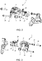
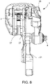
- a floating caliper 1 comprises a caliper body 2 arranged straddling a brake disc 3.
- Said brake disc 3 is rotating about a rotation axis X-X, which defines an axial direction A-A, a radial direction R-R orthogonal to said axial direction A-A, and a circumferential direction C-C orthogonal to said axial direction A-A and to said radial direction R-R.
- Said caliper body 2 is movably supported in axial direction A-A at least at one guide pin 4.
- said guide pin is firmly connected to a caliper support or caliper holder 21.
- said guide pin 4 comprises a stay bolt screwed to a threaded hole of the caliper support 21.
- said at least one guide pin 4 comprises a pin sliding portion 5 of predetermined pin axial extension L.
- Said caliper body 2 comprises a pin seat 6, which slidingly accommodates a portion of said pin sliding portion 5.
- Said pin seat 6 has a predetermined pin seat axial extension S.
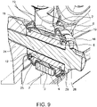
- Said floating caliper 1 further comprises a sealing arrangement 7, also referred to as “protective cap” or “sealing boot”, interposed between said pin seat 6 and said guide pin 4.
- Said sealing arrangement 4 comprises a tubular-shaped sealing arrangement body 8 made in one piece, which crosses said entire pin seat 6.
- Said sealing arrangement 4 comprises a sealing arrangement outer surface 9 in contact with said pin seat 6.
- Said sealing arrangement 4 comprises sealing arrangement inner surface 10 in contact with said pin sliding portion 5.
- sealing arrangement outer surface 9 or sealing arrangement inner surface 10 comprises an axial extension C, which is smaller than the pin seat axial extension S or the length of the pin sliding portion L, respectively, thus creating, in at least one position of the floating caliper 1 during the axial sliding thereof, at least one sealing arrangement channel 11 between said sealing arrangement 4 and said pin seat 6 or said pin sliding portion 5.
- Said at least one sealing arrangement channel 11 is open, i.e. it comes out of said pin seat 6.
- said floating caliper 1 is slidingly supported by a caliper support 21 by a first guide pin or main guide pin 30, and a second guide pin or secondary guide pin 4.
- the main guide pin 30 is accommodated in a main guide pin seat 31 and protected by a main guide pin sealing arrangement 32.
- the sealing arrangement 32 remains crimped to the support and the nut screw, thus creating a single component.
- thrust means e.g., a piston 33 accommodated in a cylinder 34 provided in the caliper body 2 and actuated by pressurized fluid fed to the caliper body by feeding lines provided with a bleeding device 35
- said thrust means stress a first pad 27 to abut against a first braking surface of the brake disc 3.
- the floating caliper slides on said main guide pin 30 and secondary guide pin 4 and stresses an opposite pad 27 facing an opposite braking surface of the brake disc 3.
- said sealing arrangement inner surface 10 comprises an axial extension C, which is smaller than the length of the pin sliding portion L, thus creating, in at least one position of the floating caliper 1 during the axial sliding thereof, at least one sealing arrangement channel 11 between said sealing arrangement 4 and said pin sliding portion 5.
- said sealing arrangement 7 comprises a sealing arrangement foot 12, which forms said sealing arrangement inner surface 10 and has a sealing arrangement foot thickness 13, assessed in a section obtained by means of a plane comprising an axial direction A-A and a radial direction R-R equal to the predetermined distance between said pin sliding portion 5 and said pin seat 6.
- the remaining sealing arrangement portions of said sealing arrangement 7 have a sealing arrangement thickness 13, assessed in a section obtained by means of a plane comprising an axial direction A-A and a radial direction R-R, which is less than said sealing arrangement foot 12 thickness.
- said sealing arrangement foot 12 has a section, in a plane comprising an axial direction A-A and a radial direction R-R, which is substantially trapezoidal in shape, with smaller base facing said pin sliding portion 5.
- said sealing arrangement foot 12 delimits two opposite sealing arrangement channels 11 between said sealing arrangement 7 and said pin sliding portion 5.
- said sealing arrangement 4 comprises at least one coupling portion 15 accommodated in a pin coupling seat 16, thus restraining said sealing arrangement 4 to said pin sliding portion 5.
- Said sealing arrangement channel 11 is open and in communication with said coupling portion 15.
- said sealing arrangement 4 comprises two coupling portions 15 accommodated in two pin coupling seats 16 arranged opposite to each other relative to said pin seat 6. Each coupling portion 15 accommodated in said pin coupling seats 16 constrains said sealing arrangement 4 to said pin sliding portion 5.
- Said sealing arrangement channel 11 is open and in communication with one of said coupling portions 15.
- said sealing arrangement 4 comprises at least one folding sealing arrangement portion 17.
- Said folding sealing arrangement portion 17 forms at least two loops 18, 19, in particular a folding sealing arrangement portion axial loop 18 and a folding sealing arrangement portion radial loop 19.
- Said folding sealing arrangement portion axial loop 18 has concavity facing the axial direction A-A.
- Said folding sealing arrangement portion radial loop 19 has concavity facing the radial direction R-R.
- said sealing arrangement 4 comprises two folding sealing arrangement portions 17 placed on opposite sides to said pin seat 6.
- a first folding sealing arrangement portion 17 is placed close to a caliper support 21 and forms at least two loops 18, 19, in particular, a folding sealing arrangement portion axial loop 18 and a folding sealing arrangement portion radial loop 19.
- Said folding sealing arrangement portion axial loop 18 has concavity facing the axial direction A-A away from said caliper support 21.
- Said folding sealing arrangement portion radial loop 19 has concavity facing the radial direction R-R, facing towards said guide pin 4.
- a second folding sealing arrangement portion 17 is placed on the opposite side of the pin seat 6 relative to a caliper support 21 and forms at least two loops 18, 19, in particular, a folding sealing arrangement portion axial loop 18 and a folding sealing arrangement portion radial loop 19.
- Said folding sealing arrangement portion axial loop 18 has concavity facing the axial direction A-A, facing towards said caliper support 21.
- Said folding sealing arrangement portion radial loop 19 has concavity facing the radial direction R-R, facing towards said guide pin 4.
- said pin seat 6 is delimited on the side away from a caliper support 21, by an opposite supporting seat edge 20.
- Said pin seat 6 is delimited on the side facing a caliper support 21 by a supporting side seat edge 22.
- Said pin seat 6 is delimited by a pin seat inner surface 24, which extends between said opposite supporting seat edge 20 and said supporting side seat edge 22.
- Said sealing arrangement 7 comprises a seat sealing arrangement length 23 embraces said opposite supporting seat edge 20, said pin seat inner surface 24, said supporting side seat edge 22.
- said sealing arrangement 7 comprises a seat sealing arrangement length 23 adhering both to said opposite supporting seat edge 20, and to said pin seat inner surface 24 and to said supporting side seat edge 22.
- said pin sliding portion 5 is a bushing 25 fitted over said guide pin 4.
- Said guide pin 4 comprises, for example, a stay bolt 29 firmly connected to a caliper support 21 onto which said bushing 25 is fitted.
- said sealing arrangement 4 comprises at least one coupling portion 15 accommodated in a pin coupling seat 16 provided in said bushing 25, thus constraining said sealing arrangement 4 to said bushing 25.
- Said sealing arrangement channel 11 is open and in communication with said coupling portion 15.
- said sealing arrangement 4 comprises two coupling portions 15 placed at the opposite ends of said sealing arrangement 7 and accommodated in two respective pin coupling seats 16 provided in said bushing 25, constraining said sealing arrangement 4 to said bushing 25.
- Said sealing arrangement channel 11 is open and in communication with one of said coupling portions 15.
- said bushing 25 is sandwiched between a guide pin head 26 provided in said stay bolt 29 and said caliper support 21.
- the present invention further relates to a method for moving a floating caliper with the wearing of the friction material of the pads 27, which abut against opposite braking surfaces of a brake disc 3.
- This method for moving a floating caliper 1 provides sliding said floating caliper 1 over at least one guide pin 4 during the action of braking and wearing the pads 27 and brake disc 28.
- Said method comprises at least the following steps:
Landscapes
- Engineering & Computer Science (AREA)
- General Engineering & Computer Science (AREA)
- Mechanical Engineering (AREA)
- Braking Arrangements (AREA)
Applications Claiming Priority (1)
| Application Number | Priority Date | Filing Date | Title |
|---|---|---|---|
| IT102021000014294A IT202100014294A1 (it) | 2021-06-01 | 2021-06-01 | Pinza flottante |
Publications (2)
| Publication Number | Publication Date |
|---|---|
| EP4098902A1 true EP4098902A1 (de) | 2022-12-07 |
| EP4098902B1 EP4098902B1 (de) | 2025-09-03 |
Family
ID=77519596
Family Applications (1)
| Application Number | Title | Priority Date | Filing Date |
|---|---|---|---|
| EP22176650.4A Active EP4098902B1 (de) | 2021-06-01 | 2022-06-01 | Schwimmender bremssattel |
Country Status (5)
| Country | Link |
|---|---|
| US (1) | US20220381304A1 (de) |
| EP (1) | EP4098902B1 (de) |
| CN (1) | CN115435030A (de) |
| CA (1) | CA3161327A1 (de) |
| IT (1) | IT202100014294A1 (de) |
Families Citing this family (1)
| Publication number | Priority date | Publication date | Assignee | Title |
|---|---|---|---|---|
| IT202200027102A1 (it) | 2022-12-29 | 2024-06-29 | Raicam Driveline S R L | Pinza freno flottante con corpo realizzato parzialmente in materiale plastico |
Citations (14)
| Publication number | Priority date | Publication date | Assignee | Title |
|---|---|---|---|---|
| US4311219A (en) * | 1978-11-16 | 1982-01-19 | Akebono Brake Industry Co., Ltd. | Caliper guiding mechanism for disc brake |
| GB2174157A (en) * | 1985-04-22 | 1986-10-29 | Teves Gmbh Alfred | Dust cover for cylindrical elements, in particular for a pin guide arrangement of a spot-type disc brake |
| US4685686A (en) | 1984-05-19 | 1987-08-11 | Alfred Teves Gmbh | Sealing cap for a bolt guide of a spot-type disc brake |
| US4961480A (en) * | 1986-10-01 | 1990-10-09 | Alfred Teves Gmbh | Pin guiding and/or damping sleeve for floating-caliper spot-type disc brakes |
| US5036957A (en) * | 1989-01-28 | 1991-08-06 | General Motors France | Disc brake and sealing boot therefor |
| US5299665A (en) * | 1989-02-09 | 1994-04-05 | Alfred Teves Gmbh | Damping bushing |
| JP2004036799A (ja) | 2002-07-04 | 2004-02-05 | Nissin Kogyo Co Ltd | バーハンドル車両用後輪ブレーキ |
| WO2012156849A1 (en) * | 2011-05-13 | 2012-11-22 | Freni Brembo S.P.A. | Floating calliper for disc brake |
| EP3246585A1 (de) * | 2016-05-18 | 2017-11-22 | Newbridge Brake Ltd. | Dichtungsanordnung für einen messschieber |
| JP2017214962A (ja) | 2016-05-31 | 2017-12-07 | 日信工業株式会社 | 車両用ディスクブレーキのキャリパボディ及びキャリパボディ製造方法 |
| JP2019128023A (ja) | 2018-01-26 | 2019-08-01 | 日信工業株式会社 | 車両用ディスクブレーキ |
| US20200056668A1 (en) * | 2017-04-24 | 2020-02-20 | Knorr-Bremse Systeme Fuer Nutzfahrzeuge Gmbh | Disc Brake for a Utility Vehicle |
| EP3633224A1 (de) | 2018-10-02 | 2020-04-08 | Nissin Kogyo Co., Ltd. | Sattelträger für eine fahrzeugscheibenbremse |
| WO2020189356A1 (ja) | 2019-03-19 | 2020-09-24 | 日信工業株式会社 | 車両用ディスクブレーキのキャリパボディ |
Family Cites Families (13)
| Publication number | Priority date | Publication date | Assignee | Title |
|---|---|---|---|---|
| GB1506718A (en) * | 1974-11-05 | 1978-04-12 | Girling Ltd | Disc brakes for vehicles |
| GB1548878A (en) * | 1975-07-01 | 1979-07-18 | Girling Ltd | Booted guide assembly |
| US4334599A (en) * | 1980-08-18 | 1982-06-15 | The Bendix Corporation | Disc brake and mounting pin assembly therefor |
| JPS5920031U (ja) * | 1982-07-28 | 1984-02-07 | トヨタ自動車株式会社 | ピンスライド式可動キヤリパ型デイスクブレ−キ |
| GB2182990B (en) * | 1985-11-15 | 1989-09-27 | Nippon Air Brake Co | Disc brake |
| JPS62132043A (ja) * | 1985-12-05 | 1987-06-15 | Akebono Brake Ind Co Ltd | キヤリパ支持構造 |
| JPH0529537Y2 (de) * | 1988-07-13 | 1993-07-28 | ||
| US5927446A (en) * | 1995-11-07 | 1999-07-27 | Kelsey-Hayes Company | Slide pin bushing and boot seal assembly for disc brake assembly |
| US6039156A (en) * | 1997-06-17 | 2000-03-21 | Kelsey Hayes Company | Slide pin bushing for disc brake assembly |
| GB0004953D0 (en) * | 2000-03-02 | 2000-04-19 | Meritor Heavy Vehicle Braking | Seal |
| JP2006071041A (ja) * | 2004-09-03 | 2006-03-16 | Honda Motor Co Ltd | 鞍乗り型不整地走行車両のブレーキキャリパ構造 |
| DE102012021690A1 (de) * | 2012-11-07 | 2014-05-08 | Knorr-Bremse Systeme für Nutzfahrzeuge GmbH | Scheibenbremse für ein Nutzfahrzeug |
| US9136572B2 (en) * | 2013-07-26 | 2015-09-15 | Raytheon Company | Dual stripline tile circulator utilizing thick film post-fired substrate stacking |
-
2021
- 2021-06-01 IT IT102021000014294A patent/IT202100014294A1/it unknown
-
2022
- 2022-06-01 CN CN202210618209.9A patent/CN115435030A/zh active Pending
- 2022-06-01 CA CA3161327A patent/CA3161327A1/en active Pending
- 2022-06-01 EP EP22176650.4A patent/EP4098902B1/de active Active
- 2022-06-01 US US17/804,857 patent/US20220381304A1/en active Pending
Patent Citations (14)
| Publication number | Priority date | Publication date | Assignee | Title |
|---|---|---|---|---|
| US4311219A (en) * | 1978-11-16 | 1982-01-19 | Akebono Brake Industry Co., Ltd. | Caliper guiding mechanism for disc brake |
| US4685686A (en) | 1984-05-19 | 1987-08-11 | Alfred Teves Gmbh | Sealing cap for a bolt guide of a spot-type disc brake |
| GB2174157A (en) * | 1985-04-22 | 1986-10-29 | Teves Gmbh Alfred | Dust cover for cylindrical elements, in particular for a pin guide arrangement of a spot-type disc brake |
| US4961480A (en) * | 1986-10-01 | 1990-10-09 | Alfred Teves Gmbh | Pin guiding and/or damping sleeve for floating-caliper spot-type disc brakes |
| US5036957A (en) * | 1989-01-28 | 1991-08-06 | General Motors France | Disc brake and sealing boot therefor |
| US5299665A (en) * | 1989-02-09 | 1994-04-05 | Alfred Teves Gmbh | Damping bushing |
| JP2004036799A (ja) | 2002-07-04 | 2004-02-05 | Nissin Kogyo Co Ltd | バーハンドル車両用後輪ブレーキ |
| WO2012156849A1 (en) * | 2011-05-13 | 2012-11-22 | Freni Brembo S.P.A. | Floating calliper for disc brake |
| EP3246585A1 (de) * | 2016-05-18 | 2017-11-22 | Newbridge Brake Ltd. | Dichtungsanordnung für einen messschieber |
| JP2017214962A (ja) | 2016-05-31 | 2017-12-07 | 日信工業株式会社 | 車両用ディスクブレーキのキャリパボディ及びキャリパボディ製造方法 |
| US20200056668A1 (en) * | 2017-04-24 | 2020-02-20 | Knorr-Bremse Systeme Fuer Nutzfahrzeuge Gmbh | Disc Brake for a Utility Vehicle |
| JP2019128023A (ja) | 2018-01-26 | 2019-08-01 | 日信工業株式会社 | 車両用ディスクブレーキ |
| EP3633224A1 (de) | 2018-10-02 | 2020-04-08 | Nissin Kogyo Co., Ltd. | Sattelträger für eine fahrzeugscheibenbremse |
| WO2020189356A1 (ja) | 2019-03-19 | 2020-09-24 | 日信工業株式会社 | 車両用ディスクブレーキのキャリパボディ |
Also Published As
| Publication number | Publication date |
|---|---|
| CA3161327A1 (en) | 2022-12-01 |
| US20220381304A1 (en) | 2022-12-01 |
| EP4098902B1 (de) | 2025-09-03 |
| CN115435030A (zh) | 2022-12-06 |
| IT202100014294A1 (it) | 2022-12-01 |
Similar Documents
| Publication | Publication Date | Title |
|---|---|---|
| US4458790A (en) | Caliper mounting suspension | |
| CN104271978B (zh) | 带有复位装置的盘式制动器和制动衬片 | |
| US4854423A (en) | Hydraulic disc brake drum-in-hat parking brake assembly | |
| US4044864A (en) | Disc brake | |
| EP2171304B1 (de) | Fahrzeugscheibenbremsvorrichtung | |
| EP2959178B1 (de) | Scheibenbremsenanordnung mit verdrehungsgesichertem fahrzeugteil und verfahren zur herstellung davon | |
| EP3121477B1 (de) | Scheibenbremsanordnung | |
| JPS591823A (ja) | 円板ブレ−キ | |
| GB2130319A (en) | Improvements in and relating to brake pads | |
| US4074795A (en) | Caliper mounting arrangement for a disc brake | |
| US6719105B1 (en) | Pad retraction spring for disc brake assembly | |
| KR101238254B1 (ko) | 마찰 요소 및 디스크 브레이크 | |
| US4082167A (en) | Sliding caliper-type disc brake and support structure therefore | |
| EP4098902B1 (de) | Schwimmender bremssattel | |
| CN110199137A (zh) | 盘式制动器 | |
| US7721854B1 (en) | Assured running clearance caliper | |
| US4350229A (en) | Disc brake having a slidably supported caliper | |
| US4265341A (en) | Easy-to-assemble sliding arrangement in disc brake | |
| US4265342A (en) | Disc brake assembly with torque absorbing bracket | |
| US4662484A (en) | Pin boot protector in disc brake assembly | |
| US4776435A (en) | Disk brake with pair of guide pins and with center of gravity positioned to minimize uneven brake lining wear | |
| US4343381A (en) | Disc brake friction pad retaining means and guide seal | |
| US3414090A (en) | Actuator guide means for disc brake | |
| GB1597778A (en) | Spot-type discbrake | |
| USRE32470E (en) | Disc brakes for vehicles |
Legal Events
| Date | Code | Title | Description |
|---|---|---|---|
| PUAI | Public reference made under article 153(3) epc to a published international application that has entered the european phase |
Free format text: ORIGINAL CODE: 0009012 |
|
| STAA | Information on the status of an ep patent application or granted ep patent |
Free format text: STATUS: THE APPLICATION HAS BEEN PUBLISHED |
|
| AK | Designated contracting states |
Kind code of ref document: A1 Designated state(s): AL AT BE BG CH CY CZ DE DK EE ES FI FR GB GR HR HU IE IS IT LI LT LU LV MC MK MT NL NO PL PT RO RS SE SI SK SM TR |
|
| STAA | Information on the status of an ep patent application or granted ep patent |
Free format text: STATUS: REQUEST FOR EXAMINATION WAS MADE |
|
| 17P | Request for examination filed |
Effective date: 20230502 |
|
| RBV | Designated contracting states (corrected) |
Designated state(s): AL AT BE BG CH CY CZ DE DK EE ES FI FR GB GR HR HU IE IS IT LI LT LU LV MC MK MT NL NO PL PT RO RS SE SI SK SM TR |
|
| P01 | Opt-out of the competence of the unified patent court (upc) registered |
Effective date: 20230526 |
|
| STAA | Information on the status of an ep patent application or granted ep patent |
Free format text: STATUS: EXAMINATION IS IN PROGRESS |
|
| 17Q | First examination report despatched |
Effective date: 20241008 |
|
| GRAP | Despatch of communication of intention to grant a patent |
Free format text: ORIGINAL CODE: EPIDOSNIGR1 |
|
| STAA | Information on the status of an ep patent application or granted ep patent |
Free format text: STATUS: GRANT OF PATENT IS INTENDED |
|
| INTG | Intention to grant announced |
Effective date: 20250502 |
|
| GRAS | Grant fee paid |
Free format text: ORIGINAL CODE: EPIDOSNIGR3 |
|
| GRAA | (expected) grant |
Free format text: ORIGINAL CODE: 0009210 |
|
| STAA | Information on the status of an ep patent application or granted ep patent |
Free format text: STATUS: THE PATENT HAS BEEN GRANTED |
|
| AK | Designated contracting states |
Kind code of ref document: B1 Designated state(s): AL AT BE BG CH CY CZ DE DK EE ES FI FR GB GR HR HU IE IS IT LI LT LU LV MC MK MT NL NO PL PT RO RS SE SI SK SM TR |
|
| REG | Reference to a national code |
Ref country code: CH Ref legal event code: EP |
|
| REG | Reference to a national code |
Ref country code: DE Ref legal event code: R096 Ref document number: 602022020565 Country of ref document: DE |
|
| REG | Reference to a national code |
Ref country code: IE Ref legal event code: FG4D |
|
| REG | Reference to a national code |
Ref country code: NL Ref legal event code: MP Effective date: 20250903 |
|
| PG25 | Lapsed in a contracting state [announced via postgrant information from national office to epo] |
Ref country code: NO Free format text: LAPSE BECAUSE OF FAILURE TO SUBMIT A TRANSLATION OF THE DESCRIPTION OR TO PAY THE FEE WITHIN THE PRESCRIBED TIME-LIMIT Effective date: 20251203 |
|
| REG | Reference to a national code |
Ref country code: LT Ref legal event code: MG9D |
|
| PG25 | Lapsed in a contracting state [announced via postgrant information from national office to epo] |
Ref country code: FI Free format text: LAPSE BECAUSE OF FAILURE TO SUBMIT A TRANSLATION OF THE DESCRIPTION OR TO PAY THE FEE WITHIN THE PRESCRIBED TIME-LIMIT Effective date: 20250903 |
|
| PG25 | Lapsed in a contracting state [announced via postgrant information from national office to epo] |
Ref country code: HR Free format text: LAPSE BECAUSE OF FAILURE TO SUBMIT A TRANSLATION OF THE DESCRIPTION OR TO PAY THE FEE WITHIN THE PRESCRIBED TIME-LIMIT Effective date: 20250903 |
|
| PG25 | Lapsed in a contracting state [announced via postgrant information from national office to epo] |
Ref country code: GR Free format text: LAPSE BECAUSE OF FAILURE TO SUBMIT A TRANSLATION OF THE DESCRIPTION OR TO PAY THE FEE WITHIN THE PRESCRIBED TIME-LIMIT Effective date: 20251204 |
|
| PG25 | Lapsed in a contracting state [announced via postgrant information from national office to epo] |
Ref country code: SE Free format text: LAPSE BECAUSE OF FAILURE TO SUBMIT A TRANSLATION OF THE DESCRIPTION OR TO PAY THE FEE WITHIN THE PRESCRIBED TIME-LIMIT Effective date: 20250903 |
|
| PG25 | Lapsed in a contracting state [announced via postgrant information from national office to epo] |
Ref country code: LV Free format text: LAPSE BECAUSE OF FAILURE TO SUBMIT A TRANSLATION OF THE DESCRIPTION OR TO PAY THE FEE WITHIN THE PRESCRIBED TIME-LIMIT Effective date: 20250903 |
|
| PG25 | Lapsed in a contracting state [announced via postgrant information from national office to epo] |
Ref country code: BG Free format text: LAPSE BECAUSE OF FAILURE TO SUBMIT A TRANSLATION OF THE DESCRIPTION OR TO PAY THE FEE WITHIN THE PRESCRIBED TIME-LIMIT Effective date: 20250903 Ref country code: PL Free format text: LAPSE BECAUSE OF FAILURE TO SUBMIT A TRANSLATION OF THE DESCRIPTION OR TO PAY THE FEE WITHIN THE PRESCRIBED TIME-LIMIT Effective date: 20250903 |
|
| PG25 | Lapsed in a contracting state [announced via postgrant information from national office to epo] |
Ref country code: RS Free format text: LAPSE BECAUSE OF FAILURE TO SUBMIT A TRANSLATION OF THE DESCRIPTION OR TO PAY THE FEE WITHIN THE PRESCRIBED TIME-LIMIT Effective date: 20251203 |
|
| PG25 | Lapsed in a contracting state [announced via postgrant information from national office to epo] |
Ref country code: ES Free format text: LAPSE BECAUSE OF FAILURE TO SUBMIT A TRANSLATION OF THE DESCRIPTION OR TO PAY THE FEE WITHIN THE PRESCRIBED TIME-LIMIT Effective date: 20250903 |
|
| REG | Reference to a national code |
Ref country code: AT Ref legal event code: MK05 Ref document number: 1833364 Country of ref document: AT Kind code of ref document: T Effective date: 20250903 |
|
| PG25 | Lapsed in a contracting state [announced via postgrant information from national office to epo] |
Ref country code: NL Free format text: LAPSE BECAUSE OF FAILURE TO SUBMIT A TRANSLATION OF THE DESCRIPTION OR TO PAY THE FEE WITHIN THE PRESCRIBED TIME-LIMIT Effective date: 20250903 |
|
| PG25 | Lapsed in a contracting state [announced via postgrant information from national office to epo] |
Ref country code: SM Free format text: LAPSE BECAUSE OF FAILURE TO SUBMIT A TRANSLATION OF THE DESCRIPTION OR TO PAY THE FEE WITHIN THE PRESCRIBED TIME-LIMIT Effective date: 20250903 |
|
| PG25 | Lapsed in a contracting state [announced via postgrant information from national office to epo] |
Ref country code: AT Free format text: LAPSE BECAUSE OF FAILURE TO SUBMIT A TRANSLATION OF THE DESCRIPTION OR TO PAY THE FEE WITHIN THE PRESCRIBED TIME-LIMIT Effective date: 20250903 |
|
| PG25 | Lapsed in a contracting state [announced via postgrant information from national office to epo] |
Ref country code: IT Free format text: LAPSE BECAUSE OF FAILURE TO SUBMIT A TRANSLATION OF THE DESCRIPTION OR TO PAY THE FEE WITHIN THE PRESCRIBED TIME-LIMIT Effective date: 20250903 |
|
| PG25 | Lapsed in a contracting state [announced via postgrant information from national office to epo] |
Ref country code: IS Free format text: LAPSE BECAUSE OF FAILURE TO SUBMIT A TRANSLATION OF THE DESCRIPTION OR TO PAY THE FEE WITHIN THE PRESCRIBED TIME-LIMIT Effective date: 20260103 |
|
| PG25 | Lapsed in a contracting state [announced via postgrant information from national office to epo] |
Ref country code: CZ Free format text: LAPSE BECAUSE OF FAILURE TO SUBMIT A TRANSLATION OF THE DESCRIPTION OR TO PAY THE FEE WITHIN THE PRESCRIBED TIME-LIMIT Effective date: 20250903 Ref country code: PT Free format text: LAPSE BECAUSE OF FAILURE TO SUBMIT A TRANSLATION OF THE DESCRIPTION OR TO PAY THE FEE WITHIN THE PRESCRIBED TIME-LIMIT Effective date: 20260105 |
|
| PG25 | Lapsed in a contracting state [announced via postgrant information from national office to epo] |
Ref country code: EE Free format text: LAPSE BECAUSE OF FAILURE TO SUBMIT A TRANSLATION OF THE DESCRIPTION OR TO PAY THE FEE WITHIN THE PRESCRIBED TIME-LIMIT Effective date: 20250903 Ref country code: SK Free format text: LAPSE BECAUSE OF FAILURE TO SUBMIT A TRANSLATION OF THE DESCRIPTION OR TO PAY THE FEE WITHIN THE PRESCRIBED TIME-LIMIT Effective date: 20250903 |