EP4098422B1 - Form, blasformvorrichtung und spritzgiessvorrichtung - Google Patents
Form, blasformvorrichtung und spritzgiessvorrichtung Download PDFInfo
- Publication number
- EP4098422B1 EP4098422B1 EP21747411.3A EP21747411A EP4098422B1 EP 4098422 B1 EP4098422 B1 EP 4098422B1 EP 21747411 A EP21747411 A EP 21747411A EP 4098422 B1 EP4098422 B1 EP 4098422B1
- Authority
- EP
- European Patent Office
- Prior art keywords
- mold
- preform
- neck
- unit
- blow
- Prior art date
- Legal status (The legal status is an assumption and is not a legal conclusion. Google has not performed a legal analysis and makes no representation as to the accuracy of the status listed.)
- Active
Links
Images


Classifications
-
- B—PERFORMING OPERATIONS; TRANSPORTING
- B29—WORKING OF PLASTICS; WORKING OF SUBSTANCES IN A PLASTIC STATE IN GENERAL
- B29C—SHAPING OR JOINING OF PLASTICS; SHAPING OF MATERIAL IN A PLASTIC STATE, NOT OTHERWISE PROVIDED FOR; AFTER-TREATMENT OF THE SHAPED PRODUCTS, e.g. REPAIRING
- B29C49/00—Blow-moulding, i.e. blowing a preform or parison to a desired shape within a mould; Apparatus therefor
- B29C49/28—Blow-moulding apparatus
- B29C49/30—Blow-moulding apparatus having movable moulds or mould parts
- B29C49/32—Blow-moulding apparatus having movable moulds or mould parts moving "to and fro"
-
- B—PERFORMING OPERATIONS; TRANSPORTING
- B29—WORKING OF PLASTICS; WORKING OF SUBSTANCES IN A PLASTIC STATE IN GENERAL
- B29C—SHAPING OR JOINING OF PLASTICS; SHAPING OF MATERIAL IN A PLASTIC STATE, NOT OTHERWISE PROVIDED FOR; AFTER-TREATMENT OF THE SHAPED PRODUCTS, e.g. REPAIRING
- B29C33/00—Moulds or cores; Details thereof or accessories therefor
- B29C33/56—Coatings, e.g. enameled or galvanised; Releasing, lubricating or separating agents
- B29C33/60—Releasing, lubricating or separating agents
-
- B—PERFORMING OPERATIONS; TRANSPORTING
- B29—WORKING OF PLASTICS; WORKING OF SUBSTANCES IN A PLASTIC STATE IN GENERAL
- B29C—SHAPING OR JOINING OF PLASTICS; SHAPING OF MATERIAL IN A PLASTIC STATE, NOT OTHERWISE PROVIDED FOR; AFTER-TREATMENT OF THE SHAPED PRODUCTS, e.g. REPAIRING
- B29C45/00—Injection moulding, i.e. forcing the required volume of moulding material through a nozzle into a closed mould; Apparatus therefor
- B29C45/17—Component parts, details or accessories; Auxiliary operations
- B29C45/26—Moulds
- B29C45/2602—Mould construction elements
- B29C45/2606—Guiding or centering means
-
- B—PERFORMING OPERATIONS; TRANSPORTING
- B29—WORKING OF PLASTICS; WORKING OF SUBSTANCES IN A PLASTIC STATE IN GENERAL
- B29C—SHAPING OR JOINING OF PLASTICS; SHAPING OF MATERIAL IN A PLASTIC STATE, NOT OTHERWISE PROVIDED FOR; AFTER-TREATMENT OF THE SHAPED PRODUCTS, e.g. REPAIRING
- B29C45/00—Injection moulding, i.e. forcing the required volume of moulding material through a nozzle into a closed mould; Apparatus therefor
- B29C45/17—Component parts, details or accessories; Auxiliary operations
- B29C45/72—Heating or cooling
- B29C45/7207—Heating or cooling of the moulded articles
-
- B—PERFORMING OPERATIONS; TRANSPORTING
- B29—WORKING OF PLASTICS; WORKING OF SUBSTANCES IN A PLASTIC STATE IN GENERAL
- B29C—SHAPING OR JOINING OF PLASTICS; SHAPING OF MATERIAL IN A PLASTIC STATE, NOT OTHERWISE PROVIDED FOR; AFTER-TREATMENT OF THE SHAPED PRODUCTS, e.g. REPAIRING
- B29C49/00—Blow-moulding, i.e. blowing a preform or parison to a desired shape within a mould; Apparatus therefor
- B29C49/42—Component parts, details or accessories; Auxiliary operations
- B29C49/4205—Handling means, e.g. transfer, loading or discharging means
- B29C49/42065—Means specially adapted for transporting preforms
-
- B—PERFORMING OPERATIONS; TRANSPORTING
- B29—WORKING OF PLASTICS; WORKING OF SUBSTANCES IN A PLASTIC STATE IN GENERAL
- B29C—SHAPING OR JOINING OF PLASTICS; SHAPING OF MATERIAL IN A PLASTIC STATE, NOT OTHERWISE PROVIDED FOR; AFTER-TREATMENT OF THE SHAPED PRODUCTS, e.g. REPAIRING
- B29C49/00—Blow-moulding, i.e. blowing a preform or parison to a desired shape within a mould; Apparatus therefor
- B29C49/42—Component parts, details or accessories; Auxiliary operations
- B29C49/48—Moulds
- B29C49/4823—Moulds with incorporated heating or cooling means
-
- B—PERFORMING OPERATIONS; TRANSPORTING
- B29—WORKING OF PLASTICS; WORKING OF SUBSTANCES IN A PLASTIC STATE IN GENERAL
- B29C—SHAPING OR JOINING OF PLASTICS; SHAPING OF MATERIAL IN A PLASTIC STATE, NOT OTHERWISE PROVIDED FOR; AFTER-TREATMENT OF THE SHAPED PRODUCTS, e.g. REPAIRING
- B29C49/00—Blow-moulding, i.e. blowing a preform or parison to a desired shape within a mould; Apparatus therefor
- B29C49/42—Component parts, details or accessories; Auxiliary operations
- B29C49/64—Heating or cooling preforms, parisons or blown articles
- B29C49/6409—Thermal conditioning of preforms
- B29C49/6427—Cooling of preforms
- B29C49/6435—Cooling of preforms from the outside
-
- B—PERFORMING OPERATIONS; TRANSPORTING
- B29—WORKING OF PLASTICS; WORKING OF SUBSTANCES IN A PLASTIC STATE IN GENERAL
- B29C—SHAPING OR JOINING OF PLASTICS; SHAPING OF MATERIAL IN A PLASTIC STATE, NOT OTHERWISE PROVIDED FOR; AFTER-TREATMENT OF THE SHAPED PRODUCTS, e.g. REPAIRING
- B29C45/00—Injection moulding, i.e. forcing the required volume of moulding material through a nozzle into a closed mould; Apparatus therefor
- B29C45/17—Component parts, details or accessories; Auxiliary operations
- B29C45/72—Heating or cooling
- B29C45/7207—Heating or cooling of the moulded articles
- B29C2045/7214—Preform carriers for cooling preforms
-
- B—PERFORMING OPERATIONS; TRANSPORTING
- B29—WORKING OF PLASTICS; WORKING OF SUBSTANCES IN A PLASTIC STATE IN GENERAL
- B29C—SHAPING OR JOINING OF PLASTICS; SHAPING OF MATERIAL IN A PLASTIC STATE, NOT OTHERWISE PROVIDED FOR; AFTER-TREATMENT OF THE SHAPED PRODUCTS, e.g. REPAIRING
- B29C49/00—Blow-moulding, i.e. blowing a preform or parison to a desired shape within a mould; Apparatus therefor
- B29C49/02—Combined blow-moulding and manufacture of the preform or the parison
- B29C2049/023—Combined blow-moulding and manufacture of the preform or the parison using inherent heat of the preform, i.e. 1 step blow moulding
-
- B—PERFORMING OPERATIONS; TRANSPORTING
- B29—WORKING OF PLASTICS; WORKING OF SUBSTANCES IN A PLASTIC STATE IN GENERAL
- B29C—SHAPING OR JOINING OF PLASTICS; SHAPING OF MATERIAL IN A PLASTIC STATE, NOT OTHERWISE PROVIDED FOR; AFTER-TREATMENT OF THE SHAPED PRODUCTS, e.g. REPAIRING
- B29C49/00—Blow-moulding, i.e. blowing a preform or parison to a desired shape within a mould; Apparatus therefor
- B29C49/42—Component parts, details or accessories; Auxiliary operations
- B29C49/48—Moulds
- B29C49/4823—Moulds with incorporated heating or cooling means
- B29C2049/4838—Moulds with incorporated heating or cooling means for heating moulds or mould parts
-
- B—PERFORMING OPERATIONS; TRANSPORTING
- B29—WORKING OF PLASTICS; WORKING OF SUBSTANCES IN A PLASTIC STATE IN GENERAL
- B29C—SHAPING OR JOINING OF PLASTICS; SHAPING OF MATERIAL IN A PLASTIC STATE, NOT OTHERWISE PROVIDED FOR; AFTER-TREATMENT OF THE SHAPED PRODUCTS, e.g. REPAIRING
- B29C49/00—Blow-moulding, i.e. blowing a preform or parison to a desired shape within a mould; Apparatus therefor
- B29C49/42—Component parts, details or accessories; Auxiliary operations
- B29C49/48—Moulds
- B29C2049/4879—Moulds characterised by mould configurations
- B29C2049/4892—Mould halves consisting of an independent main and bottom part
-
- B—PERFORMING OPERATIONS; TRANSPORTING
- B29—WORKING OF PLASTICS; WORKING OF SUBSTANCES IN A PLASTIC STATE IN GENERAL
- B29C—SHAPING OR JOINING OF PLASTICS; SHAPING OF MATERIAL IN A PLASTIC STATE, NOT OTHERWISE PROVIDED FOR; AFTER-TREATMENT OF THE SHAPED PRODUCTS, e.g. REPAIRING
- B29C2949/00—Indexing scheme relating to blow-moulding
- B29C2949/07—Preforms or parisons characterised by their configuration
- B29C2949/0715—Preforms or parisons characterised by their configuration the preform having one end closed
-
- B—PERFORMING OPERATIONS; TRANSPORTING
- B29—WORKING OF PLASTICS; WORKING OF SUBSTANCES IN A PLASTIC STATE IN GENERAL
- B29C—SHAPING OR JOINING OF PLASTICS; SHAPING OF MATERIAL IN A PLASTIC STATE, NOT OTHERWISE PROVIDED FOR; AFTER-TREATMENT OF THE SHAPED PRODUCTS, e.g. REPAIRING
- B29C49/00—Blow-moulding, i.e. blowing a preform or parison to a desired shape within a mould; Apparatus therefor
- B29C49/02—Combined blow-moulding and manufacture of the preform or the parison
- B29C49/06—Injection blow-moulding
- B29C49/061—Injection blow-moulding with parison holding means displaceable between injection and blow stations
- B29C49/062—Injection blow-moulding with parison holding means displaceable between injection and blow stations following an arcuate path, e.g. rotary or oscillating-type
-
- B—PERFORMING OPERATIONS; TRANSPORTING
- B29—WORKING OF PLASTICS; WORKING OF SUBSTANCES IN A PLASTIC STATE IN GENERAL
- B29C—SHAPING OR JOINING OF PLASTICS; SHAPING OF MATERIAL IN A PLASTIC STATE, NOT OTHERWISE PROVIDED FOR; AFTER-TREATMENT OF THE SHAPED PRODUCTS, e.g. REPAIRING
- B29C49/00—Blow-moulding, i.e. blowing a preform or parison to a desired shape within a mould; Apparatus therefor
- B29C49/42—Component parts, details or accessories; Auxiliary operations
- B29C49/4205—Handling means, e.g. transfer, loading or discharging means
- B29C49/42073—Grippers
- B29C49/42087—Grippers holding outside the neck
-
- B—PERFORMING OPERATIONS; TRANSPORTING
- B29—WORKING OF PLASTICS; WORKING OF SUBSTANCES IN A PLASTIC STATE IN GENERAL
- B29C—SHAPING OR JOINING OF PLASTICS; SHAPING OF MATERIAL IN A PLASTIC STATE, NOT OTHERWISE PROVIDED FOR; AFTER-TREATMENT OF THE SHAPED PRODUCTS, e.g. REPAIRING
- B29C49/00—Blow-moulding, i.e. blowing a preform or parison to a desired shape within a mould; Apparatus therefor
- B29C49/42—Component parts, details or accessories; Auxiliary operations
- B29C49/64—Heating or cooling preforms, parisons or blown articles
- B29C49/6409—Thermal conditioning of preforms
- B29C49/6427—Cooling of preforms
-
- B—PERFORMING OPERATIONS; TRANSPORTING
- B29—WORKING OF PLASTICS; WORKING OF SUBSTANCES IN A PLASTIC STATE IN GENERAL
- B29L—INDEXING SCHEME ASSOCIATED WITH SUBCLASS B29C, RELATING TO PARTICULAR ARTICLES
- B29L2031/00—Other particular articles
- B29L2031/712—Containers; Packaging elements or accessories, Packages
- B29L2031/7158—Bottles
Definitions
- the present invention relates to a mold, a blow molding apparatus, and an injection molding apparatus.
- Blow molding (“hot parison” process) apparatuses are one of commonly known apparatuses for producing resin containers.
- preforms are blow-molded into resin containers as the preforms are intermittently transferred sequentially from one to another of an injection molding unit, a temperature adjusting unit, and a blow molding unit, on a rotating transfer plate.
- the above blow molding apparatus forms resin containers by utilizing the residual heat contained in injection-molded preforms, which offers advantage over a "cold parison” process in producing a wide variety of resin containers with good appearance.
- EP0347506A2 discloses a self-lubricating metallic matrix for injection molding.
- WO2019/170976A1 discloses a locking finger for a unit for moulding containers made of thermoplastic material.
- DE202006011657U1 discloses a guide column bearing, e.g. for moving platens on an injection molding machine, that includes lubrication with viscous lubricant in addition to a solid lubricant.
- JP2014091321A discloses a self-lubricating sliding body.
- JP2014151562A discloses a mold for plastic molding and an injection molding method.
- WO2018/159745A1 discloses a molding mold.
- the mold used in the blow molding apparatus described above is made up of a plurality of mold components, many of which are driven by actuators. These mold components must be positioned precisely relative to the preform when the mold is closed for favorable molding of the preforms or resin containers.
- mold components that face each other have inclined surfaces, for example, which slide against one another, to ensure accuracy in positioning the mold components that hold and transfer the preforms and other mold components.
- Application of lubricant to numerous parts of a blow molding apparatus is a cumbersome task. Absence of lubricant by oversight can significantly increase risk of damage to the mold components.
- the present invention was made in view of this problem, and aims at providing a mold that can reduce the workload of lubricant application while preventing galling on surfaces between a mold that holds preforms and another mold.
- the present invention in one aspect resides in a mold including a first mold for receiving a neck mold that holds a neck part of a resin preform having a bottom, and for enclosing the preform inside, and a second mold inserted into the neck mold, at least one of a first sliding surface between the neck mold and the first mold and a second sliding surface between the neck mold and the second mold including a solid lubricant embedded therein.
- the workload of lubricant application is reduced, and galling on surfaces between a mold that holds preforms and another mold can be prevented.
- Fig. 1 is a schematic diagram illustrating the configuration of the blow molding apparatus in one embodiment.
- the blow molding apparatus in this embodiment is a "hot parison" process (herein also referred to as a one-stage process) apparatus in which preforms are not cooled down to room temperature and blow-molded into containers utilizing the residual heat (internal energy) from the injection molding step retained in the preforms.
- the transfer mechanism 26 includes a rotating plate 26a (not shown in Fig. 1 ) that rotates around an axis perpendicular to the paper plane of Fig. 1 .
- neck molds 27 (not shown in Fig. 1 ) that hold neck parts 12 of preforms 11 or resin containers (hereinafter simply "container") 15, one or more at every predetermined angle.
- the transfer mechanism 26 rotates the rotating plate 26a and transports preforms 11 (or containers 15), held by the neck molds 27 at their neck parts 12, sequentially from one to another of the injection molding unit 21, temperature adjusting unit 22, blow molding unit 23, and ejection unit 24.
- the transfer mechanism 26 is also able to move the rotating plate 26a up and down, and to perform operations relating to the closing and opening of the mold (demolding) of the preforms 11 in the injection molding unit 21.
- the cavity 41 is a mold having a temperature adjusting space 41a of substantially the same shape as that of the preform 11 produced at the injection molding unit 21, i.e., is able to accommodate a preform 11 inside.
- Air outlet holes 41c are formed in a bottom part of the temperature adjusting space 41a of the cavity 41 for letting out the air as the preform 11 is being inserted.
- a plurality of solid lubricants 28 are embedded at equal intervals in an annular form along the outer circumference of the core 42 in a tapered proximal end part 42a of the core 42 that slides against the inner circumferential surface 27b of the neck mold 27.
- a plurality of solid lubricants 28 are embedded at equal intervals in an annular form along the inner circumference of the cavity 41 in a tapered bearing surface 41b of the cavity 41 that receives the neck mold 27.
- solid lubricants 28 are embedded in the outer circumferential surface 27a and inner circumferential surface 27b of the neck mold 27 that transfers the preform 11.
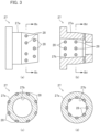
- the blow molding unit 23 includes a blow mold cavity 51 that is a pair of split mold halves corresponding to the shape of the container 15, a bottom mold 52, and an air injection member (not shown) that doubles as a stretch rod.
- Fig. 5(a) illustrates a state before the blow mold cavity 51 and bottom mold 52 are closed
- Fig. 5(b) illustrates a state after the blow mold cavity 51 and bottom mold 52 have been closed.
- the blow mold cavity 51 is a mold part that defines the shape of the container 15 except for the bottom surface.
- the blow mold cavity 51 is split in a parting plane along the up-down direction in Fig. 5 and configured to be opened and closed in the left-right direction in Fig. 5 .
- the blow mold cavity 51 is one example of a first mold.
- the bottom mold 52 is a mold that defines the shape of the bottom surface of the container 15 and is disposed below the blow mold cavity 51.
- a mold cavity that defines the shape of the container 15 is formed by the bottom mold 52 and the blow mold cavity 51 being closed.
- the bottom mold 52 waits below the preform 11 where it does not touch the bottom of the preform 11 before the blow mold cavity 51 is closed, for example, and is driven to move up quickly to a molding position ( Fig. 5(b) ) after the mold is closed.
- the air injection member which is a hollow tubular body for blowing air into the preform, is brought into contact with the neck part of the preform.
- the air injection member is movable up and down in the drawing and serves to stretch the preform 11 along the vertical axis by moving down.
- the air injection member is one example of a second mold.
- Solid lubricants 28 are embedded in third sliding surfaces between the blow mold cavity 51 and the bottom mold 52. These solid lubricants 28 embedded in the sliding surfaces can minimize galling of the mold components of the blow mold cavity 51 and bottom mold 52. Although not shown in Fig. 5 , solid lubricants 28 are embedded in respective first sliding surfaces between the blow mold cavity 51 and the outer circumferential surface 27a of the neck mold 27, and second sliding surfaces between the inner circumferential surface 27b of the neck mold 27 and the air injection member.
- a plurality of solid lubricants 28 are embedded at equal intervals in an annular form along the outer circumference of the bottom mold 52 in a cylindrical or tapered proximal end part (contact part) 52a of bottom mold 52 that slides against the blow mold cavity 51.
- a plurality of solid lubricants 28 are embedded at equal intervals in an annular form along the inner circumference of a cylindrical or tapered opening 51a in the blow mold cavity 51 that receives the proximal end part 52a of the bottom mold 52 (bearing surface that receives the proximal end part 52a of the bottom mold 52).
- the bottom mold 52 further includes a forming part 52c that defines the bottom surface shape of the container 15, a cylindrical or tapered middle part 52b that connects the forming part 52c and the proximal end part 52a, and a step 52d that connects the middle part 52b and the proximal end part 52a and defines an uppermost position of the bottom mold 52.
- the proximal end part 52a has a larger diameter than the middle part 52b.
- the blow mold cavity 51 further includes a second opening 51b that is cylindrical or tapered in a portion that faces or opposes the middle part 52b when the mold is closed.
- the opening 51a has a larger diameter than the second opening 51b.
- No solid lubricants 28 are embedded in the outer circumferential surface of the middle part 52b and the inner circumferential surface of the second opening 51b and they are configured such that there is a predetermined gap between them, this gap serving as an air vent.
- the ejection unit 24 is configured to release the neck part 12 of the container produced at the blow molding unit 23 from the neck mold 27 and allow the container to be taken out of the blow molding apparatus 20.
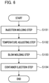
- Fig. 6 is a flowchart illustrating the steps of the blow molding method.
- resin material is injected from the injection device 25 into the mold cavity formed by the injection mold cavity 31, injection mold core 32, and the neck mold 27 of the transfer mechanism 26 at the injection molding unit 21 to produce a preform 11.
- the rotating plate 26a of the transfer mechanism 26 rotates a predetermined angle so that the preform 11 held by the neck mold 27 and containing the residual heat from the injection molding step is transferred to the temperature adjusting unit 22.
- Step S102 Temperature adjusting step
- the temperature of the preform 11 is adjusted to be closer to a temperature suitable for final blow molding.
- the preform 11 is accommodated inside the temperature adjusting space 41a of the cavity 41.
- the core 42 is inserted into the preform 11 held in the cavity 41.
- the preform 11 Since the cavity 41 and the core 42 are configured to conform to the shape of the preform 11, the preform 11 remains in a desired shape even during the temperature adjusting step.
- the blow mold cavity 51 is closed to accommodate the preform 11 in the mold cavity.
- the bottom mold 52 waits below far enough not to touch the bottom part of the preform 11 before the blow mold cavity 51 is closed. After the blow mold cavity 51 is closed, the bottom mold 52 is then quickly lifted to a molding position.
- Step S104 Container ejection step
- the molds are opened in the blow molding unit 23. This allows the container 15 to be moved away from the blow molding unit 23.
- the blow molding apparatus 20a includes a preform supply unit 60, a blow molding unit 23, a heating unit 62 (temperature adjusting unit 22a in a broader sense), a transfer mechanism 26, and a container ejection unit 61.
- the heating unit 62 includes a looped heated transfer path, and a heating device (not shown) such as an infrared heater that can heat up the body part of the preform to a temperature suitable for blowing.
- the preform supply unit 60 receives preforms (made of PET, for example) that were produced and prepared beforehand in an injection molding apparatus elsewhere, and loads the same onto the first holding member 26a1.
- the container ejection unit 61 includes a container holding part (not shown) disposed adjacent the blow molding unit 23 for receiving containers that were produced in the blow molding unit 23 and transported thereto by the third holding member 26c1.
- the heating unit 62 heats the preform held on the first holding member 26a1, as the preform is spun and transported inside the heating device.
- preforms fed by the preform supply unit 60 are heated in the heating unit 62 up to a temperature suited for blowing (100 to 110°C, for example), after which the preforms are transferred to the blow molding unit 23.
- the preform is accommodated in a mold made up of a blow mold cavity 51 and a bottom mold 52, and blow-molded into a container of a desired shape. After the blow molding, the containers are transferred to the container ejection unit 61.
- Fig. 7(B) is a schematic diagram illustrating the configuration of a two-stage injection molding apparatus 70.
- the injection molding apparatus 70 carries out injection molding of preforms, wherein a resin material (PET, for example) is injected from the injection device 25 into a mold cavity formed by a neck mold 27, an injection mold cavity 31, and an injection mold core 32 that are clamped together in the injection molding unit 21.
- the preforms are then removed in a hot state (with the outer surface temperature in the body part being 100 to 130°C, for example), after which they are transferred to the cooling unit 72.
- the preforms are cooled to the extent that no shrinkage deformation such as sink marks will occur if left under normal temperature (with the outer surface temperature in the body part being 50 to 60°C, for example). Once the preforms are sufficiently cooled, they are transported to the ejection unit 71 next.
Landscapes
- Engineering & Computer Science (AREA)
- Mechanical Engineering (AREA)
- Manufacturing & Machinery (AREA)
- Physics & Mathematics (AREA)
- Thermal Sciences (AREA)
- Blow-Moulding Or Thermoforming Of Plastics Or The Like (AREA)
- Moulds For Moulding Plastics Or The Like (AREA)
Claims (8)
- Formwerkzeug, umfassend:ein erstes Formwerkzeug (31, 41, 51) zum Aufnehmen eines Halsformwerkzeugs (27), das einen Halsteil (12) einer Harzvorform (11) mit einem Boden hält, und zum Umschließen der Vorform (11) im Inneren;
undein zweites Formwerkzeug (32, 42), das in das Halsformwerkzeug (27) eingebracht ist,dadurch gekennzeichnet, dass zumindest eines aus einer ersten Gleitfläche zwischen dem Halsformwerkzeug (27) und dem ersten Formwerkzeug (31, 41, 51) und einer zweiten Gleitfläche zwischen dem Halsformwerkzeug (27) und dem zweiten Formwerkzeug (32, 42) ein darin eingebettetes festes Schmiermittel (28) umfasst. - Formwerkzeug nach Anspruch 1, wobeidas feste Schmiermittel (28) in der ersten Gleitfläche in zumindest einer aus einer Außenumfangsfläche des Halsformwerkzeugs (27) und einer Oberfläche des ersten Formwerkzeugs (31, 41, 51) eingebettet ist unddas feste Schmiermittel (28) in der zweiten Gleitfläche in zumindest einer aus einer Innenumfangsfläche des Halsformwerkzeugs (27) und einer Oberfläche des zweiten Formwerkzeugs (32, 42) eingebettet ist.
- Formwerkzeug nach Anspruch 1 oder 2, wobei
das Formwerkzeug ein Formwerkzeug, das zum Spritzgießen der Vorform (11) verwendet wird, oder ein Temperaturanpassungsformwerkzeug, das zum Abkühlen der nach dem Spritzgießen entformten Vorform (11) verwendet wird, ist. - Formwerkzeug nach Anspruch 1 oder 2, wobei
das Formwerkzeug ein Formwerkzeug ist, das zum Blasformen der Vorform (11) verwendet wird. - Formwerkzeug nach Anspruch 4, ferner umfassend:ein Bodenformwerkzeug (52), das in das erste Formwerkzeug (31, 41, 51) eingebracht ist und eine Bodenflächenform von blasgeformten Behältern definiert,wobei ein festes Schmiermittel (28) in einer dritten Gleitfläche zwischen dem ersten Formwerkzeug (31, 41, 51) und dem Bodenformwerkzeug (52) eingebettet ist.
- Blasformvorrichtung (20, 20a), das ein Formwerkzeug nach einem der Ansprüche 1 bis 5 umfasst.
- Spritzformvorrichtung (70), das ein Formwerkzeug nach Anspruch 1 oder 2 umfasst und durch Einspritzen von Harzmaterial in das Formwerkzeug Vorformen (11) formt.
- Formwerkzeug zur Verwendung bei der Herstellung von Behältern durch Blasformen von Harzvorformen (11), die einen Boden aufweisen, umfassend:ein Hohlraumformwerkzeug, das eine Körperform der Behälter definiert und dazu vorgesehen ist, die Vorformen (11) darin aufzunehmen, undein Bodenformwerkzeug (52), das eine Bodenflächenform der Behälter definiert und in das Hohlraumformwerkzeug eingebracht ist,dadurch gekennzeichnet, dass das Hohlraumformwerkzeug und das Bodenformwerkzeug (52) ein festes Schmiermittel (28) aufweisen, das in einer Gleitfläche zwischen diesen eingebettet ist.
Applications Claiming Priority (2)
| Application Number | Priority Date | Filing Date | Title |
|---|---|---|---|
| JP2020015318 | 2020-01-31 | ||
| PCT/JP2021/003043 WO2021153671A1 (ja) | 2020-01-31 | 2021-01-28 | 金型、ブロー成形装置および射出成形装置 |
Publications (4)
| Publication Number | Publication Date |
|---|---|
| EP4098422A1 EP4098422A1 (de) | 2022-12-07 |
| EP4098422A4 EP4098422A4 (de) | 2024-03-27 |
| EP4098422C0 EP4098422C0 (de) | 2025-07-09 |
| EP4098422B1 true EP4098422B1 (de) | 2025-07-09 |
Family
ID=77079130
Family Applications (1)
| Application Number | Title | Priority Date | Filing Date |
|---|---|---|---|
| EP21747411.3A Active EP4098422B1 (de) | 2020-01-31 | 2021-01-28 | Form, blasformvorrichtung und spritzgiessvorrichtung |
Country Status (5)
| Country | Link |
|---|---|
| US (1) | US12280531B2 (de) |
| EP (1) | EP4098422B1 (de) |
| JP (1) | JP7344993B2 (de) |
| CN (1) | CN115038567B (de) |
| WO (1) | WO2021153671A1 (de) |
Families Citing this family (1)
| Publication number | Priority date | Publication date | Assignee | Title |
|---|---|---|---|---|
| EP4656348A2 (de) * | 2023-08-21 | 2025-12-03 | Ritter GmbH | Verwendung von pcr material und digitaler direktdruck auf kartuschen |
Family Cites Families (20)
| Publication number | Priority date | Publication date | Assignee | Title |
|---|---|---|---|---|
| JPS60134615A (ja) | 1983-12-23 | 1985-07-17 | Nec Corp | 電圧制御減衰器 |
| JPS60134615U (ja) | 1984-02-16 | 1985-09-07 | 積水化学工業株式会社 | 射出成形金型 |
| JPH01320121A (ja) | 1988-06-22 | 1989-12-26 | Sankyo Eng Kk | 射出成形用無給油金型 |
| JP3001055U (ja) | 1994-02-15 | 1994-08-16 | 武雄 角岡 | 射出成形装置におけるスライドコア及びそのガイドレール |
| JP3573374B2 (ja) * | 1995-05-08 | 2004-10-06 | 株式会社青木固研究所 | 射出延伸吹込成形におけるプリフォーム成形方法 |
| US7377477B2 (en) * | 2004-02-11 | 2008-05-27 | Diamond Innovations, Inc. | Product forming molds and methods to manufacture same |
| DE202006011657U1 (de) | 2006-07-26 | 2006-12-14 | Mht Mold & Hotrunner Technology Ag | Säulenführung |
| US20090068301A1 (en) * | 2007-09-07 | 2009-03-12 | Wen-Hua Huang | Protection Structure for an Optical Lens Module |
| JP4819178B1 (ja) * | 2010-10-27 | 2011-11-24 | 株式会社タカノ | 潤滑性部材及びその製造方法 |
| WO2013012067A1 (ja) * | 2011-07-20 | 2013-01-24 | 日精エー・エス・ビー機械株式会社 | プリフォームの温度調整装置及びプリフォームの温度調整方法、樹脂製容器及び樹脂製容器の製造方法 |
| JP5888731B2 (ja) | 2012-01-31 | 2016-03-22 | 日精エー・エス・ビー機械株式会社 | 金型装置及び射出成形装置並びに射出成形方法 |
| JP2014091321A (ja) * | 2012-10-31 | 2014-05-19 | Hidetoshi Otani | 自己潤滑摺動体 |
| JP6095216B2 (ja) | 2013-02-08 | 2017-03-15 | 本田技研工業株式会社 | プラスチック成形用金型及び射出成形方法 |
| JP6647144B2 (ja) * | 2015-12-11 | 2020-02-14 | 株式会社青木固研究所 | 射出延伸ブロー成形機の射出成形型とプリフォームの成形方法とプリフォーム、及び容器の成形方法と容器 |
| JP6957841B2 (ja) * | 2016-07-27 | 2021-11-02 | 東洋製罐株式会社 | 合成樹脂製容器の製造方法 |
| EP3590681B1 (de) * | 2017-03-02 | 2023-05-03 | Nissei ASB Machine Co., Ltd. | Gussform |
| FR3078648B1 (fr) | 2018-03-07 | 2020-02-14 | Sidel Participations | Doigt de verrouillage pour une unite de moulage de recipients en matiere thermoplastique |
| WO2019194115A1 (ja) * | 2018-04-03 | 2019-10-10 | 日精エー・エス・ビー機械株式会社 | ブロー成形金型及びブロー成形装置 |
| FR3082773B1 (fr) * | 2018-06-21 | 2020-07-17 | Sidel Participations | Unite de moulage equipee d'un insert de boxage mobile ventile par un circuit fluidique derive du circuit fluidique de boxage |
| CN109822791A (zh) | 2019-02-28 | 2019-05-31 | 厦门市松竹精密科技有限公司 | 一种模具的顶出式滑块装置 |
-
2021
- 2021-01-28 WO PCT/JP2021/003043 patent/WO2021153671A1/ja not_active Ceased
- 2021-01-28 JP JP2021574108A patent/JP7344993B2/ja active Active
- 2021-01-28 US US17/795,439 patent/US12280531B2/en active Active
- 2021-01-28 EP EP21747411.3A patent/EP4098422B1/de active Active
- 2021-01-28 CN CN202180011705.1A patent/CN115038567B/zh active Active
Also Published As
| Publication number | Publication date |
|---|---|
| JP7344993B2 (ja) | 2023-09-14 |
| JPWO2021153671A1 (de) | 2021-08-05 |
| WO2021153671A1 (ja) | 2021-08-05 |
| US12280531B2 (en) | 2025-04-22 |
| EP4098422C0 (de) | 2025-07-09 |
| US20230049178A1 (en) | 2023-02-16 |
| CN115038567A (zh) | 2022-09-09 |
| CN115038567B (zh) | 2025-12-09 |
| EP4098422A1 (de) | 2022-12-07 |
| EP4098422A4 (de) | 2024-03-27 |
Similar Documents
| Publication | Publication Date | Title |
|---|---|---|
| EP3476567B1 (de) | Spritzgiesseinheit und blasformvorrichtung damit | |
| US11472091B2 (en) | Two step blow molding unit, apparatus and method | |
| JP7457077B2 (ja) | 首曲がり容器の製造方法、温度調整用金型、ブロー成形装置およびブロー成形方法 | |
| EP4098422B1 (de) | Form, blasformvorrichtung und spritzgiessvorrichtung | |
| EP4299278A1 (de) | Temperaturregelungsform und vorrichtung und verfahren zur herstellung eines harzbehälters | |
| US12208558B2 (en) | Manufacturing method and manufacturing apparatus for delamination container | |
| US11858194B2 (en) | Container mold and method of manufacturing a container | |
| US20240116236A1 (en) | Method for manufacturing resin container and apparatus for manufacturing same | |
| EP4324620A1 (de) | Herstellungsverfahren und herstellungsvorrichtung für harzbehälter | |
| EP4474132A1 (de) | Temperaturregelungsform sowie vorrichtung und verfahren zur herstellung eines harzbehälters | |
| EP4299279A1 (de) | Temperaturregelungsform sowie vorrichtung und verfahren zur herstellung eines harzbehälters | |
| EP4640407A1 (de) | Vorform, spritzgiessform, temperaturregelungsform, harzbehälterherstellungsverfahren und harzbehälterherstellungsvorrichtung | |
| WO2025216235A1 (ja) | 射出成形金型、樹脂製容器の製造装置および製造方法 | |
| WO2023157863A1 (ja) | 温度調整用金型、温度調整方法および樹脂製容器の製造装置 | |
| CN118613365A (zh) | 温度调整用模具、树脂制容器的制造装置 | |
| CN116261511A (zh) | 吹塑成型装置 |
Legal Events
| Date | Code | Title | Description |
|---|---|---|---|
| STAA | Information on the status of an ep patent application or granted ep patent |
Free format text: STATUS: THE INTERNATIONAL PUBLICATION HAS BEEN MADE |
|
| PUAI | Public reference made under article 153(3) epc to a published international application that has entered the european phase |
Free format text: ORIGINAL CODE: 0009012 |
|
| STAA | Information on the status of an ep patent application or granted ep patent |
Free format text: STATUS: REQUEST FOR EXAMINATION WAS MADE |
|
| 17P | Request for examination filed |
Effective date: 20220831 |
|
| AK | Designated contracting states |
Kind code of ref document: A1 Designated state(s): AL AT BE BG CH CY CZ DE DK EE ES FI FR GB GR HR HU IE IS IT LI LT LU LV MC MK MT NL NO PL PT RO RS SE SI SK SM TR |
|
| DAV | Request for validation of the european patent (deleted) | ||
| DAX | Request for extension of the european patent (deleted) | ||
| A4 | Supplementary search report drawn up and despatched |
Effective date: 20240223 |
|
| RIC1 | Information provided on ipc code assigned before grant |
Ipc: B29L 31/00 20060101ALN20240219BHEP Ipc: B29C 49/06 20060101ALN20240219BHEP Ipc: B29C 49/64 20060101ALN20240219BHEP Ipc: B29C 45/72 20060101ALI20240219BHEP Ipc: B29C 49/48 20060101ALI20240219BHEP Ipc: B29C 49/42 20060101ALI20240219BHEP Ipc: B29C 49/02 20060101ALI20240219BHEP Ipc: B29C 45/26 20060101AFI20240219BHEP |
|
| RIN1 | Information on inventor provided before grant (corrected) |
Inventor name: USAMI, MASAYUKI |
|
| GRAP | Despatch of communication of intention to grant a patent |
Free format text: ORIGINAL CODE: EPIDOSNIGR1 |
|
| STAA | Information on the status of an ep patent application or granted ep patent |
Free format text: STATUS: GRANT OF PATENT IS INTENDED |
|
| RIC1 | Information provided on ipc code assigned before grant |
Ipc: B29L 31/00 20060101ALN20250131BHEP Ipc: B29C 49/06 20060101ALN20250131BHEP Ipc: B29C 49/64 20060101ALN20250131BHEP Ipc: B29C 45/72 20060101ALI20250131BHEP Ipc: B29C 49/48 20060101ALI20250131BHEP Ipc: B29C 49/42 20060101ALI20250131BHEP Ipc: B29C 49/02 20060101ALI20250131BHEP Ipc: B29C 45/26 20060101AFI20250131BHEP |
|
| INTG | Intention to grant announced |
Effective date: 20250213 |
|
| GRAS | Grant fee paid |
Free format text: ORIGINAL CODE: EPIDOSNIGR3 |
|
| GRAA | (expected) grant |
Free format text: ORIGINAL CODE: 0009210 |
|
| STAA | Information on the status of an ep patent application or granted ep patent |
Free format text: STATUS: THE PATENT HAS BEEN GRANTED |
|
| AK | Designated contracting states |
Kind code of ref document: B1 Designated state(s): AL AT BE BG CH CY CZ DE DK EE ES FI FR GB GR HR HU IE IS IT LI LT LU LV MC MK MT NL NO PL PT RO RS SE SI SK SM TR |
|
| REG | Reference to a national code |
Ref country code: GB Ref legal event code: FG4D |
|
| REG | Reference to a national code |
Ref country code: CH Ref legal event code: EP |
|
| REG | Reference to a national code |
Ref country code: IE Ref legal event code: FG4D |
|
| U01 | Request for unitary effect filed |
Effective date: 20250711 |
|
| U07 | Unitary effect registered |
Designated state(s): AT BE BG DE DK EE FI FR IT LT LU LV MT NL PT RO SE SI Effective date: 20250717 |
|
| PG25 | Lapsed in a contracting state [announced via postgrant information from national office to epo] |
Ref country code: IS Free format text: LAPSE BECAUSE OF FAILURE TO SUBMIT A TRANSLATION OF THE DESCRIPTION OR TO PAY THE FEE WITHIN THE PRESCRIBED TIME-LIMIT Effective date: 20251109 |
|
| PG25 | Lapsed in a contracting state [announced via postgrant information from national office to epo] |
Ref country code: NO Free format text: LAPSE BECAUSE OF FAILURE TO SUBMIT A TRANSLATION OF THE DESCRIPTION OR TO PAY THE FEE WITHIN THE PRESCRIBED TIME-LIMIT Effective date: 20251009 |
|
| PG25 | Lapsed in a contracting state [announced via postgrant information from national office to epo] |
Ref country code: HR Free format text: LAPSE BECAUSE OF FAILURE TO SUBMIT A TRANSLATION OF THE DESCRIPTION OR TO PAY THE FEE WITHIN THE PRESCRIBED TIME-LIMIT Effective date: 20250709 |
|
| PG25 | Lapsed in a contracting state [announced via postgrant information from national office to epo] |
Ref country code: GR Free format text: LAPSE BECAUSE OF FAILURE TO SUBMIT A TRANSLATION OF THE DESCRIPTION OR TO PAY THE FEE WITHIN THE PRESCRIBED TIME-LIMIT Effective date: 20251010 |
|
| PG25 | Lapsed in a contracting state [announced via postgrant information from national office to epo] |
Ref country code: PL Free format text: LAPSE BECAUSE OF FAILURE TO SUBMIT A TRANSLATION OF THE DESCRIPTION OR TO PAY THE FEE WITHIN THE PRESCRIBED TIME-LIMIT Effective date: 20250709 |
|
| PG25 | Lapsed in a contracting state [announced via postgrant information from national office to epo] |
Ref country code: RS Free format text: LAPSE BECAUSE OF FAILURE TO SUBMIT A TRANSLATION OF THE DESCRIPTION OR TO PAY THE FEE WITHIN THE PRESCRIBED TIME-LIMIT Effective date: 20251009 |
|
| PG25 | Lapsed in a contracting state [announced via postgrant information from national office to epo] |
Ref country code: ES Free format text: LAPSE BECAUSE OF FAILURE TO SUBMIT A TRANSLATION OF THE DESCRIPTION OR TO PAY THE FEE WITHIN THE PRESCRIBED TIME-LIMIT Effective date: 20250709 |