EP4098298A1 - Syringe-barrel grip, barrel assembly, and syringe - Google Patents
Syringe-barrel grip, barrel assembly, and syringe Download PDFInfo
- Publication number
- EP4098298A1 EP4098298A1 EP21776305.1A EP21776305A EP4098298A1 EP 4098298 A1 EP4098298 A1 EP 4098298A1 EP 21776305 A EP21776305 A EP 21776305A EP 4098298 A1 EP4098298 A1 EP 4098298A1
- Authority
- EP
- European Patent Office
- Prior art keywords
- flange
- grip
- barrel
- pair
- syringe
- Prior art date
- Legal status (The legal status is an assumption and is not a legal conclusion. Google has not performed a legal analysis and makes no representation as to the accuracy of the status listed.)
- Granted
Links
Images





Classifications
-
- A—HUMAN NECESSITIES
- A61—MEDICAL OR VETERINARY SCIENCE; HYGIENE
- A61M—DEVICES FOR INTRODUCING MEDIA INTO, OR ONTO, THE BODY; DEVICES FOR TRANSDUCING BODY MEDIA OR FOR TAKING MEDIA FROM THE BODY; DEVICES FOR PRODUCING OR ENDING SLEEP OR STUPOR
- A61M5/00—Devices for bringing media into the body in a subcutaneous, intra-vascular or intramuscular way; Accessories therefor, e.g. filling or cleaning devices, arm-rests
- A61M5/178—Syringes
- A61M5/31—Details
- A61M5/3129—Syringe barrels
- A61M5/3137—Specially designed finger grip means, e.g. for easy manipulation of the syringe rod
-
- A—HUMAN NECESSITIES
- A61—MEDICAL OR VETERINARY SCIENCE; HYGIENE
- A61M—DEVICES FOR INTRODUCING MEDIA INTO, OR ONTO, THE BODY; DEVICES FOR TRANSDUCING BODY MEDIA OR FOR TAKING MEDIA FROM THE BODY; DEVICES FOR PRODUCING OR ENDING SLEEP OR STUPOR
- A61M5/00—Devices for bringing media into the body in a subcutaneous, intra-vascular or intramuscular way; Accessories therefor, e.g. filling or cleaning devices, arm-rests
- A61M5/178—Syringes
- A61M5/31—Details
- A61M5/3129—Syringe barrels
- A61M5/3137—Specially designed finger grip means, e.g. for easy manipulation of the syringe rod
- A61M2005/3139—Finger grips not integrally formed with the syringe barrel, e.g. using adapter with finger grips
-
- A—HUMAN NECESSITIES
- A61—MEDICAL OR VETERINARY SCIENCE; HYGIENE
- A61M—DEVICES FOR INTRODUCING MEDIA INTO, OR ONTO, THE BODY; DEVICES FOR TRANSDUCING BODY MEDIA OR FOR TAKING MEDIA FROM THE BODY; DEVICES FOR PRODUCING OR ENDING SLEEP OR STUPOR
- A61M5/00—Devices for bringing media into the body in a subcutaneous, intra-vascular or intramuscular way; Accessories therefor, e.g. filling or cleaning devices, arm-rests
- A61M5/001—Apparatus specially adapted for cleaning or sterilising syringes or needles
Definitions
- the present invention relates to a syringe barrel grip attached to a syringe barrel, and a barrel assembly and a syringe each including the syringe barrel grip.
- Some drug-filled syringes each use a plunger that is not coupled to a gasket in order to prevent medical errors.
- a clip backstop for preventing a plunger from moving to a proximal end side and falling off from a barrel is attached (Patent Literature 1).
- These clips are each fitted to an outer peripheral surface of a barrel at a cylindrical fitting portion and firmly attached to a syringe so as not to rattle or come off during operation of the syringe.
- the present invention provides a syringe barrel grip having good operability and capable of achieving higher sterility in a state of being attached to a syringe barrel, and a barrel assembly and a syringe each including such a syringe barrel grip.
- a syringe barrel grip attached to a syringe barrel including a cylindrical body and a flange disposed in the cylindrical body, protruding outward, and including a pair of flange straight portions facing each other in parallel,
- a barrel assembly including: a syringe barrel including a cylindrical body and a flange disposed at a proximal end of the cylindrical body, protruding outward, and including a pair of flange straight portions facing each other in parallel; and the syringe barrel grip attached to the barrel.
- a syringe including: the barrel assembly; a gasket slidably housed in the barrel; and a plunger for moving the gasket.
- a syringe barrel grip of the present invention and a barrel assembly and a syringe each including such a syringe barrel grip will be described with reference to an embodiment illustrated in the drawings.
- Fig. 1 the side on which a flange 22 of a syringe barrel 20 is formed
- a lower side in Fig. 1 the side on which a nozzle portion 23 of the syringe barrel 20 is disposed
- the vertical direction in Fig. 1 as an axial direction (the axial direction of the syringe barrel 20 or a cylindrical body 21).
- a syringe 1 of the present invention includes: a barrel assembly 2 including a syringe barrel 20 (hereinafter, also simply referred to as a barrel 20) and a syringe barrel grip 30 (hereinafter, also simply referred to as a grip 30) attached to the barrel 20; a gasket 11 slidably housed in the barrel 20; and a plunger 12 for moving the gasket 11.
- a barrel assembly 2 including a syringe barrel 20 (hereinafter, also simply referred to as a barrel 20) and a syringe barrel grip 30 (hereinafter, also simply referred to as a grip 30) attached to the barrel 20; a gasket 11 slidably housed in the barrel 20; and a plunger 12 for moving the gasket 11.
- the barrel 20 includes a cylindrical body 21 and a flange 22 (thickness t) disposed in the cylindrical body 21, protruding outward (in a direction orthogonal to the axial direction of the barrel 20), and including a pair of flange straight portions 24 and 24 (width w) facing each other in parallel.
- the cylindrical body 21 of the barrel 20 has a circular (annular) outer shape and a circular (annular) inner shape in a cross section taken along a plane orthogonal to the axial direction thereof as a whole.
- a distal end opening portion (nozzle portion) 23 for discharging a drug is disposed at a distal end portion of the barrel 20.
- the barrel 20 includes a collar 25 covering a proximal end side portion of the nozzle portion 23.
- a barrel side screwing portion (female screwing portion) is formed on an inner surface of the collar 25.
- the nozzle portion 23 is sealed by a seal cap 13 to prevent leakage of a drug 60 stored in the barrel 20 and to prevent the aseptically filled drug 60 from coming into contact with outside air.
- Examples of a constituent material of the barrel 20 include various resins such as a polyolefin including polyethylene and polypropylene, polystyrene, polyamide, polycarbonate, polyvinyl chloride, poly-(4-methylpentene-1), an acrylic resin, an acrylonitrile-butadiene-styrene copolymer, a polyester including polyethylene terephthalate, a cyclic polyolefin polymer, and a cyclic olefin copolymer.
- resins such as polypropylene, a cyclic polyolefin polymer, and a cyclic olefin copolymer are preferable because the resins are easily molded and have heat resistance.
- a cyclic olefin polymer or a cyclic olefin copolymer having high transparency such that a drug solution filled inside can be visually confirmed from the outside and having heat resistance capable of withstanding high-pressure steam sterilization is particularly preferable as a material for forming the barrel 20.
- the seal cap 13 includes a body portion 18 having a proximal end side hollow portion that houses the nozzle portion 23 of the barrel 20, and a seal member 19 housed in the body portion 18 and disposed at a distal end portion of the proximal end side hollow portion.
- a cap side screwing portion male screwing portion
- the barrel side screwing portion female screwing portion
- Examples of a material for forming the seal cap include various resins such as polypropylene, polyethylene, polystyrene, polyamide, polycarbonate, polyvinyl chloride, poly-(4-methylpentene-1), an acrylic resin, an acrylonitrile-butadiene-styrene copolymer, a polyester including polyethylene terephthalate, and a cyclic polyolefin.
- resins such as polypropylene and a cyclic polyolefin are preferable because the resins are easily molded and have heat resistance.
- an elastic material such as a natural rubber, a synthetic rubber including an isoprene rubber, a butyl rubber, a butadiene rubber, a fluororubber, and a silicone rubber, or a thermoplastic elastomer including an olefin-based elastomer and a styrene-based elastomer is preferable.
- the gasket 11 housed in the barrel 20 is made of an elastic rubber or a synthetic resin.
- the gasket 11 includes a substantially cylindrical body portion extending with substantially the same outer diameter and a plurality of annular ribs disposed on an outer surface of the body portion. Outer surfaces of the annular ribs are in liquid-tight contact with an inner surface of the barrel 20 and are slidable in a liquid-tight state.
- an elastic rubber for example, a butyl rubber, a latex rubber, or a silicone rubber
- a synthetic resin for example, a styrene-based elastomer such as an SBS elastomer or an SEBS elastomer, or an olefin-based elastomer such as an ethylene-a olefin copolymer elastomer
- an elastic rubber for example, a butyl rubber, a latex rubber, or a silicone rubber
- a synthetic resin for example, a styrene-based elastomer such as an SBS elastomer or an SEBS elastomer, or an olefin-based elastomer such as an ethylene-a olefin copolymer elastomer
- the plunger 12 is made of a hard or semi-hard resin.
- the plunger 12 includes a small disk-shaped gasket pressing portion 14 disposed at a distal end thereof, a disk-shaped pressing operation portion 15 disposed at a proximal end thereof, and a shaft portion 16 having a cross-shaped cross section and extending in the axial direction of the barrel 20 between the gasket pressing portion 14 and the pressing operation portion 15.
- the shaft portion 16 may be a columnar shaft.
- the columnar shaft may have a rod shape, a circular columnar shape, a polygonal columnar shape, a circular cylindrical shape, a polygonal cylindrical shape, or the like.
- the plunger 12 is not connected to the gasket 11, and can abut on a proximal end portion of the gasket 11 at the gasket pressing portion 14.
- the gasket 11 can be moved to a distal end side by pressing after abutment.
- a distal end side portion (the gasket pressing portion 14 and a part of a distal end side of the shaft portion 16) of the plunger 12 is housed in the barrel 20 (cylindrical body 21).
- the plunger 12 includes a stopper portion 17 that is disposed in a portion (shaft portion 16) housed in the barrel 20, abuts on the grip 30 (stopper abutment portion 31) described in detail later, and restricts detachment of the plunger 12 from the barrel 20. More specifically, the stopper portion 17 has a disk shape having an outer shape (outer diameter) smaller than the inner shape (inner diameter) of the barrel 20 (cylindrical body 21) and larger than the outer shape (maximum diameter portion) of the shaft portion 16 of the plunger 12.
- a hard or semi-hard resin such as high-density polyethylene, polypropylene, polystyrene, or polyethylene terephthalate is preferably used.
- the drug (drug solution) 60 is stored (filled) in the barrel 20 (in a space formed between the seal cap 13 and the gasket 11).
- the drug 60 to be stored is not particularly limited, and examples thereof include a vitamin, a sugar, an electrolyte, an organic acid, a mineral, a fat emulsion, an amino acid, a protein, and an organ preparation mainly as nutrients.
- examples thereof further include a drug for a central nervous system, such as a general anesthetic, an antipyretic analgesic, or a general cold preparation, a drug for a peripheral nervous system, such as a local anesthetic or a muscle relaxant, a drug for a sensory organ, such as an ophthalmic agent, a metabolic drug such as a circulatory drug, a respiratory drug, a digestive drug, an urogenital anal drug, a hormonal agent, an antibiotic, or a diabetes drug, a biological preparation such as an antitumor drug, an allergic drug, an antibacterial agent, or an antiviral agent, and a prescription drug such as distilled water or physiological saline mainly as therapeutic agents.
- examples thereof further include a vaccine
- drugs each contain, as a main component, a synthetic low molecular weight compound, a synthetic middle molecular weight compound, a biopharmaceutical such as a polypeptide preparation or a protein preparation, or a biologically derived pharmaceutical such as a blood preparation, but these substances can be used as drugs regardless of the applications described above.
- a substance corresponding to a molecular target drug such as an antibody can also be used as a drug.
- a dosage form of each of these drugs is preferably a liquid even in a drug having a solid dosage form such as a powder or a granule in addition to a liquid from a viewpoint of usability.
- an ophthalmic drug that can be administered by puncture can be used as the drug 60.
- a specific target disease for which such an ophthalmic drug is used include choroidal neovascularization, age-related macular degeneration (both exudative and atrophic), macular edema secondary to retinal vein occlusion (RVO) (including both branch retinal vein occlusion (bRVO) and central retinal vein occlusion (cRVO)), choroidal neovascularization secondary to pathologic myopia (PM), diabetic macular edema (DME), diabetic retinopathy, and proliferative retinopathy.
- choroidal neovascularization age-related macular degeneration (both exudative and atrophic
- macular edema secondary to retinal vein occlusion (RVO) including both branch retinal vein occlusion (bRVO) and central retinal vein occlusion (cRVO)
- ranibizumab [trade name: LUCENTIS (registered trademark)]
- bevacizumab [trade name: AVASTIN (registered trademark)]
- aflibercept [trade name: EYLEA (registered trademark)]
- VEGF-TrapEye aflibercept intravitreal injection solution
- the syringe barrel grip 30 of this embodiment includes a flange housing portion 32 that houses the flange 22.
- the flange housing portion 32 includes: a side surface opening 33 formed on a side surface of the grip 30; a flange insertion portion 34 extending in an internal direction of the grip 30 from the side surface opening 33; and a flange rotation restricting portion 35 that communicates with the flange insertion portion 34, extends into the grip 30, and restricts relative rotation between the grip 30 and the flange 22 that has entered the flange rotation restricting portion 35 by rotating the barrel 20 by a predetermined angle in a state where the flange 22 is housed in the flange insertion portion 34.
- the flange insertion portion 34 includes a first pair of grip straight portions 36 and 36 having a slightly wider width W1 than the pair of flange straight portions 24 and 24 (width w), and the flange rotation restricting portion 35 includes a second pair of grip straight portions 37 and 37 having a slightly wider width W2 than the pair of flange straight portions 24 and 24 (width w) and is inclined with respect to the first pair of grip straight portions 36 and 36.
- a protrusion 38 that abuts on the flange 22 (flange straight portion 24) when the barrel 20 is rotated and the flange 22 is caused to enter the flange rotation restricting portion 35 is formed.
- the protrusion 38 is formed in the grip 30, at an end portion of the left first grip straight portion 36 (in Fig. 10 ) of the flange insertion portion 34 on the flange rotation restricting portion 35 side (a connecting portion between the left first grip straight portion 36 and the left second grip straight portion 37).
- a stepped portion 39 which is continuous to the first grip straight portion 36 at a right angle and connects the first grip straight portion 36 and the second grip straight portion 37 to each other is formed.
- front sides of the pair of flange straight portions 24 and 24 are located in the second pair of grip straight portions 37 and 37 (between the second pair of grip straight portions 37 and 37), and rear sides of the pair of flange straight portions 24 and 24 are located in the first pair of grip straight portions 36 and 36 (between the first pair of grip straight portions 36 and 36).
- one rear end portion of the pair of flange straight portions 24 and 24 (an end portion of the flange 22 on a rear side in an insertion direction into the grip 30) abuts on or approaches one of the first pair of grip straight portions 36 and 36. That is, as illustrated in Figs. 2 and 14 , in Figs. 2 and 14 , a rear end portion of the right flange straight portion 24 abuts on or approaches the right first grip straight portion 36.
- the flange 22 housed in the flange rotation restricting portion 35 is prevented from moving (rattling) along the second pair of grip straight portions 37 and 37 and being detached from the flange rotation restricting portion 35.
- a lower inner peripheral surface of the grip 30 is not in contact with the barrel 20, and there is a gap 40 for allowing a sterilization gas to flow between the lower inner peripheral surface of the grip 30 and the barrel 20.
- the flange housing portion 32 includes an upper plate portion 41 covering a proximal end side surface of the flange 22 and a lower plate portion 42 covering a distal end side surface of the flange 22.
- a distance T between the upper plate portion 41 and the lower plate portion 42 of the flange housing portion 32 is larger than the thickness t of the flange 22.
- a gap for allowing a sterilization gas to flow is formed between the upper plate portion 41 and the proximal end side surface of the flange 22 and/or between the lower plate portion 42 and the distal end side surface of the flange 22.
- an upper slit (opening) 43 is formed in the upper plate portion 41 of the flange housing portion 32.
- the upper slit 43 communicates with the side surface opening 33, the flange insertion portion 34, and the flange rotation restricting portion 35 of the flange housing portion 32, and is formed such that the shaft portion 16 of the plunger 12 can enter the upper slit 43.
- a part of an inner edge portion of the upper slit 43 is a stopper abutment portion 31 that protrudes inward and abuts on the stopper portion 17 of the plunger 12.
- the upper slit 43 allows the shaft portion 16 of the plunger 12 to pass therethrough, and abuts on the stopper portion 17 of the plunger 12 at the stopper abutment portion 31. Therefore, as illustrated in Fig. 6 , the plunger 12 housed in the barrel 20 abuts on the stopper abutment portion 31 of the grip 30 at the stopper portion 17, whereby detachment of the plunger 12 from the barrel 20 is restricted.
- a lower slit (opening) 44 is formed in the lower plate portion 42 of the flange housing portion 32.
- the lower slit 44 communicates with the side surface opening 33, the flange insertion portion 34, and the flange rotation restricting portion 35 of the flange housing portion 32, and is formed such that the cylindrical body 21 of barrel 20 can enter the lower slit 44.
- the lower plate portion 42 (lower slit 44) includes a barrel insertion portion 46 including a pair of lower straight portions 45 and 45 that has a width W3 larger (wider) than the outer shape (outer diameter) of the barrel 20 (cylindrical body 21) portion that enters the lower slit 44 and narrower than the width w of the pair of flange straight portions 24 and 24, and are substantially parallel to the first pair of grip straight portions 36 and 36, respectively.
- the lower plate portion 42 (lower slit 44) includes a barrel housing portion 47 that communicates with the barrel insertion portion 46, and partially surrounds the barrel 20 (cylindrical body 21) (houses the barrel 20) in a state where the flange 22 is housed in the flange rotation restricting portion 35.
- the barrel housing portion 47 has an inner shape (inner diameter, radius R illustrated in Fig. 11 ) larger than the outer shape (outer diameter, radius r illustrated in Fig. 3 ) of the barrel 20 (cylindrical body 21) housed therein.
- a recess 48 is formed in an upper inner edge portion of the lower plate portion 42.
- a sterilization gas can be brought into contact with a wider area of a distal end side surface of the flange 22 facing the lower plate portion 42.
- a pair of finger hook portions 49 and 49 is formed so as to constitute a proximal end side portion of the grip 30 and to protrude outward (in a direction orthogonal to the axial direction of the barrel 20).
- the pair of finger hook portions 49 and 49 protrude in directions opposite to each other and orthogonal to the axial direction of the barrel 20.
- the pair of finger hook portions 49 and 49 extends outward from the flange 22 of the barrel 20.
- the pair of finger hook portions 49 and 49 can be used by an operator to hook a finger when the operator operates the syringe 1.
- the grip 30 of the present embodiment includes a side wall portion 50 extending to an axial distal end side from the flange housing portion 32.
- the side wall portion 50 is integrated with (connected to) an inner edge portion of the lower slit 44 of the lower plate portion 42 of the flange housing portion 32 at a proximal end thereof.
- the outer shape of the side wall portion 50 increases toward a proximal end side (flange housing portion 32 side), and is smoothly connected to the finger hook portions 49 and 49 of the flange housing portion 32.
- the side wall portion 50 contributes to improvement in operability of the syringe 1.
- An inner peripheral surface of the side wall portion 50 is formed by extending an inner peripheral surface of the lower slit 44 in the axial direction over the entire length in the axial direction, and has a semi-cylindrical shape with a substantially U-shaped cross section as a whole.
- an opening for insertion extending over the entire length in the axial direction (for insertion of a proximal end portion of the cylindrical body 21) (insertion slit) 51 is formed.
- the side wall portion 50 partially covers a proximal end portion of the cylindrical body 21 adjacent to the flange 22, and at least a part of the inner peripheral surface constitutes a lower inner peripheral surface of the grip 30 that forms a gap for allowing a sterilization gas to flow between the inner peripheral surface and the barrel 20.
- a constituent material of the grip 30 include a hard or semi-hard resin such as a polyolefin including polyethylene and polypropylene, polystyrene, polyamide, polycarbonate, polyvinyl chloride, poly-(4-methylpentene-1), an acrylic resin, an acrylonitrile-butadiene-styrene copolymer, a polyester including polyethylene terephthalate, a cyclic polyolefin polymer, or a cyclic olefin copolymer.
- a hard or semi-hard resin such as a polyolefin including polyethylene and polypropylene, polystyrene, polyamide, polycarbonate, polyvinyl chloride, poly-(4-methylpentene-1), an acrylic resin, an acrylonitrile-butadiene-styrene copolymer, a polyester including polyethylene terephthalate, a cyclic polyolefin polymer, or a cyclic ole
- a material having a thermal expansion coefficient (linear thermal expansion coefficient) larger than that of the barrel 20 may be used as a constituent material of the grip 30.
- an inner surface (inner diameter) of the grip 30 expands more than an outer surface (outer diameter) of the barrel 20 (cylindrical body 21), a gap is formed or expanded between the inner surface of the grip 30 and the outer surface of the cylindrical body 21, and a sterilization gas enters the gap, whereby sterilizability of the syringe 1 can be improved.
- a sterilization method adopted at this time is not particularly limited, and for example, an autoclave sterilization method using an autoclave (high temperature steam sterilization method), a surface sterilization method using a sterilization gas such as hydrogen peroxide or EOG (gas sterilization method), or a radiation sterilization method by radiation irradiation using a y ray, an electron radiation, or the like can be used.
- autoclave sterilization is performed.
- the drug 60 that has been previously subjected to sterilization treatment (for example, filtration sterilization) is aseptically filled in the sterilized barrel 20.
- sterilization treatment for example, filtration sterilization
- the drug 60 for ophthalmic use which is relatively vulnerable to heat, is filled.
- the gasket 11 is inserted into the barrel 20. The gasket 11 can be inserted (capped) in a depressurized state.
- a distal end side portion of the plunger 12 is housed in the barrel 20, and the grip 30 is attached to the barrel 20. Note that this operation can also be performed under an environment other than a sterile environment.
- a step of attaching the grip 30 to the barrel 20 will be described in detail with reference to Figs. 12 to 14 .
- the flange 22 of the barrel 20 is inserted into the grip 30 from the side surface opening 33, and the flange 22 is housed in the flange insertion portion 34.
- the barrel 20 is biased in a rotational direction (here, counterclockwise) and rotated.
- a rotational direction here, counterclockwise
- one (here, the left flange straight portion 24 in Fig. 13 ) of the pair of flange straight portions 24 and 24 abuts on the protrusion 38, and a rear end portion of the other (here, the right flange straight portion 24 in Fig. 13 ) or a portion in the vicinity thereof abuts on the right first grip straight portion 36 in Fig. 13 [the grip 30 (flange housing portion 32) and barrel 20 (flange 22) are temporarily engaged with each other (first engagement state)].
- the barrel 20 When the barrel 20 is further biased in the rotational direction from the state where the grip 30 and the barrel 20 are engaged with each other, the upper slit 43, the lower slit 44, and the insertion slit 51 are formed in the grip 30 (the flange housing portion 32 and the side wall portion 50), and therefore the flange housing portion 32 of the grip 30 is elastically deformed and pushed out. As a result, the rotation of the barrel 20 is allowed, the engagement state between the barrel 20 (flange 22) and the grip 30 (flange housing portion 32) is released, and the flange 22 enters the flange rotation restricting portion 35.
- the grip 30 is temporarily engaged with the barrel 20 when the flange 22 is caused to enter the flange rotation restricting portion 35 by rotating the barrel 20 by a predetermined angle in a state where the flange 22 is housed in the flange insertion portion 34.
- the grip 30 attached to the barrel 20 from unintentionally falling off.
- the grip 30 since the grip 30 is temporarily engaged with the barrel 20 (the first engagement state exists) when the flange 22 is caused to enter the flange rotation restricting portion 35 by rotating the barrel 20 by a predetermined angle in a state where the flange 22 is housed in the flange insertion portion 34, the second engagement state occurs in the flange 22 once housed in the flange pivoting restriction portion 35, and detachment of the grip 30 from the barrel 20 after attachment can be prevented.
- the syringe 1 with the grip 30 attached to the barrel 20 is sterilized.
- the drug 60 stored in the barrel 20 is a drug for ophthalmic use, which is relatively vulnerable to heat
- surface sterilization (NO 2 sterilization) using a sterilization gas here, NO 2 (nitrogen dioxide) is performed.
- the syringe 1 can be aseptically manufactured.
- the grip 30 (flange housing portion 32) of the present embodiment includes the flange rotation restricting portion 35 including the second pair of grip straight portions 37 and 37 that is inclined with respect to the first pair of grip straight portions 36 and 36 disposed in the flange insertion portion 34, and in a state where the flange 22 is stored in the flange rotation restricting portion 35, a part of the pair of flange straight portions 24 and 24 is located in the second pair of grip straight portions 37 and 37. Therefore, relative rotation between the flange 22 (barrel 20) and the grip 30 is restricted in a state where the grip 30 is attached to the syringe barrel 20, and therefore operability is good.
- a lower inner peripheral surface of the grip 30 (an inner peripheral surface of the lower slit 44 of the lower plate portion 42 and/or an inner peripheral surface of the side wall portion 50) is not in contact with the barrel 20, and there is a gap 40 for allowing a sterilization gas to flow between the lower inner peripheral surface of the grip 30 and the barrel 20. Therefore, the sterilization gas can be brought into contact with a wider area of surfaces of the grip 30 and the barrel 20, and the syringe barrel grip 30 and the syringe barrel 20 to which such a grip 30 is attached are more reliably sterilized.
- the cylindrical body 21 of the barrel 20 has a circular cylindrical shape in which the cross sections of the outer shape and the inner shape are substantially circular, but the present invention is not limited thereto. It is possible to appropriately use those having various cylindrical shapes in which the cross sections are elliptical, polygonal, and the like, those having different cross-sectional shapes between the outer shape and the inner shape, and the like, and the shape of the grip 30 (flange housing portion 32) can also be appropriately changed accordingly.
- a lower plate portion 42a of a flange housing portion 32a constitutes a most distal end portion (lowest portion) of the grip 30a.
- the grip 30a can be further reduced in size and weight.
- a lower plate portion 42b of a flange housing portion 32b is thicker than the grip 30a (lower plate portion 42a) described above.
- the strength of the grip 30b can be increased.
- an inner peripheral surface (inner shape) of the lower plate portion 42b expands downward.
- a flow of a sterilization gas between the grip 30b and the barrel 20 is further promoted while the strength of the grip 30b is increased by thickening the lower plate portion 42b, and the sterilization is more reliably performed.
- a right first grip straight portion 36c and a right second grip straight portion 37c in Fig. 17 in a flange housing portion 32c may be connected to each other as they are without forming the stepped portion (39).
- a right first grip straight portion 36d and a right second grip straight portion 37d in Fig. 18 in a flange housing portion 32d may be connected to each other at a gentle angle with an inclined stepped portion 39d.
- the protrusion 38 formed in the flange housing portion 32 is not limited to the exemplified one.
- the protrusion 38 may be formed so as to protrude from the first grip straight portion 36 toward the inside of the flange housing portion 32, and as for a formation portion thereof, the protrusion 38 may be formed at a middle portion of the first grip straight portion 36 instead of the end portion of the first grip straight portion 36 on the flange rotation restricting portion 35 side.
- the syringe barrel grip of the present invention is as follows.
- the syringe barrel grip of the present invention is attached to a syringe barrel including a cylindrical body and a flange disposed in the cylindrical body, protruding outward, and including a pair of flange straight portions facing each other in parallel.
- the grip of the present invention includes a flange housing portion that houses a flange, and the flange housing portion includes: a side surface opening formed on a side surface of the grip; a flange insertion portion extending in an internal direction of the grip from the side surface opening; and a flange rotation restricting portion that communicates with the flange insertion portion, extends into the grip, and restricts relative rotation between the grip and the flange that has entered the flange rotation restricting portion by rotating the barrel by a predetermined angle in a state where the flange is housed in the flange insertion portion.
- the flange insertion portion of the grip of the present invention includes a first pair of grip straight portions having a slightly wider width than the pair of flange straight portions
- the flange rotation restricting portion includes a second pair of grip straight portions having a slightly wider width than the pair of flange straight portions and is inclined with respect to the first pair of grip straight portions, and in a state where the flange is housed in the flange rotation restricting portion, front sides of the pair of flange straight portions are located in the second pair of grip straight portions, and rear sides of the pair of flange straight portions are located in the first pair of grip straight portions.
- a lower inner peripheral surface of the grip is not in contact with the barrel, and there is a gap for allowing a sterilization gas to flow between the lower inner peripheral surface of the grip and the barrel.
- the sterilization gas can be brought into contact with a wider area of surfaces of the grip and the barrel, and the syringe barrel grip and a syringe barrel to which such a grip is attached are more reliably sterilized.
- the flange housing portion includes an upper plate portion covering a proximal end side surface of the flange and a lower plate portion covering a distal end side surface of the flange, a distance between the upper plate portion and the lower plate portion is larger than the thickness of the flange, and a gap for allowing a sterilization gas to flow is formed between the upper plate portion and the proximal end side surface of the flange and/or between the lower plate portion and the distal end side surface of the flange.
- the barrel assembly of the present invention is as follows.
- a barrel assembly including: a syringe barrel including a cylindrical body and a flange disposed at a proximal end of the cylindrical body, protruding outward, and including a pair of flange straight portions facing each other in parallel; and the syringe barrel grip according to any one of (1) to (4) attached to the barrel.
- the barrel assembly of the present invention includes a syringe barrel grip attached to a syringe barrel including a cylindrical body and a flange disposed in the cylindrical body, protruding outward, and including a pair of flange straight portions facing each other in parallel.
- the grip includes a flange housing portion that houses a flange, and the flange housing portion includes: a side surface opening formed on a side surface of the grip; a flange insertion portion extending in an internal direction of the grip from the side surface opening; and a flange rotation restricting portion that communicates with the flange insertion portion, extends into the grip, and restricts relative rotation between the grip and the flange that has entered the flange rotation restricting portion by rotating the barrel by a predetermined angle in a state where the flange is housed in the flange insertion portion.
- the flange insertion portion of the grip includes a first pair of grip straight portions having a slightly wider width than the pair of flange straight portions
- the flange rotation restricting portion includes a second pair of grip straight portions having a slightly wider width than the pair of flange straight portions and is inclined with respect to the first pair of grip straight portions, and in a state where the flange is housed in the flange rotation restricting portion, front sides of the pair of flange straight portions are located in the second pair of grip straight portions, and rear sides of the pair of flange straight portions are located in the first pair of grip straight portions.
- a lower inner peripheral surface of the grip is not in contact with the barrel, and there is a gap for allowing a sterilization gas to flow between the lower inner peripheral surface of the grip and the barrel.
- the sterilization gas can be brought into contact with a wider area of surfaces of the grip and the barrel, and the syringe barrel grip and a syringe barrel to which such a grip is attached are more reliably sterilized.
- the syringe of the present invention is as follows.
- a syringe including: the barrel assembly according to (5); a gasket slidably housed in the barrel; and a plunger for moving the gasket.
- the syringe of the present invention includes a syringe barrel grip attached to a syringe barrel including a cylindrical body and a flange disposed in the cylindrical body, protruding outward, and including a pair of flange straight portions facing each other in parallel.
- the grip includes a flange housing portion that houses a flange, and the flange housing portion includes: a side surface opening formed on a side surface of the grip; a flange insertion portion extending in an internal direction of the grip from the side surface opening; and a flange rotation restricting portion that communicates with the flange insertion portion, extends into the grip, and restricts relative rotation between the grip and the flange that has entered the flange rotation restricting portion by rotating the barrel by a predetermined angle in a state where the flange is housed in the flange insertion portion.
- the flange insertion portion of the grip includes a first pair of grip straight portions having a slightly wider width than the pair of flange straight portions
- the flange rotation restricting portion includes a second pair of grip straight portions having a slightly wider width than the pair of flange straight portions and is inclined with respect to the first pair of grip straight portions, and in a state where the flange is housed in the flange rotation restricting portion, front sides of the pair of flange straight portions are located in the second pair of grip straight portions, and rear sides of the pair of flange straight portions are located in the first pair of grip straight portions.
- a lower inner peripheral surface of the grip is not in contact with the barrel, and there is a gap for allowing a sterilization gas to flow between the lower inner peripheral surface of the grip and the barrel.
- the sterilization gas can be brought into contact with a wider area of surfaces of the grip and the barrel, and the syringe barrel grip and a syringe barrel to which such a grip is attached are more reliably sterilized.
Landscapes
- Health & Medical Sciences (AREA)
- Vascular Medicine (AREA)
- Engineering & Computer Science (AREA)
- Anesthesiology (AREA)
- Biomedical Technology (AREA)
- Heart & Thoracic Surgery (AREA)
- Hematology (AREA)
- Life Sciences & Earth Sciences (AREA)
- Animal Behavior & Ethology (AREA)
- General Health & Medical Sciences (AREA)
- Public Health (AREA)
- Veterinary Medicine (AREA)
- Infusion, Injection, And Reservoir Apparatuses (AREA)
- Apparatus For Disinfection Or Sterilisation (AREA)
Abstract
Description
- The present invention relates to a syringe barrel grip attached to a syringe barrel, and a barrel assembly and a syringe each including the syringe barrel grip.
- Some drug-filled syringes (prefilled syringes) each use a plunger that is not coupled to a gasket in order to prevent medical errors. To such a prefilled syringe, a clip (backstop) for preventing a plunger from moving to a proximal end side and falling off from a barrel is attached (Patent Literature 1).
- In addition, in order to facilitate gripping and operation of a syringe, it is also known to attach a clip (grip) including a finger hook portion protruding outward to a proximal end portion of a barrel (Patent Literature 2) .
- These clips are each fitted to an outer peripheral surface of a barrel at a cylindrical fitting portion and firmly attached to a syringe so as not to rattle or come off during operation of the syringe.
-
- Patent Literature 1:
JP 2015-517860 A US 2015-105734 A1 andUS 2019-365565 A1 ) - Patent Literature 2:
WO 2017/073658 A (US 2018-243509 A1 ) - In recent years, in ophthalmic use and the like, higher sterility of not only a drug to be administered and a portion in contact with the drug but also the entire prefilled syringe including a grip is required. Therefore, the present inventors have studied an application of a surface sterilization method with a small heat load, such as hydrogen peroxide sterilization, EOG sterilization, or NO2 sterilization, to a prefilled syringe to which a grip is attached. These surface sterilization methods perform sterilization with a gas (sterilization gas), and in order to achieve higher sterility, the sterilization gas preferably comes into contact with a wider area of a surface of the prefilled syringe.
- Therefore, the present invention provides a syringe barrel grip having good operability and capable of achieving higher sterility in a state of being attached to a syringe barrel, and a barrel assembly and a syringe each including such a syringe barrel grip.
- The above object is achieved by the following.
- A syringe barrel grip attached to a syringe barrel including a cylindrical body and a flange disposed in the cylindrical body, protruding outward, and including a pair of flange straight portions facing each other in parallel,
- the grip including a flange housing portion that houses the flange, in which
- the flange housing portion includes: a side surface opening formed on a side surface of the grip; a flange insertion portion extending in an internal direction of the grip from the side surface opening; and a flange rotation restricting portion that communicates with the flange insertion portion, extends into the grip, and restricts relative rotation between the grip and the flange that has entered the flange rotation restricting portion by rotating the barrel by a predetermined angle in a state where the flange is housed in the flange insertion portion,
- the flange insertion portion includes a first pair of grip straight portions having a slightly wider width than the pair of flange straight portions, and the flange rotation restricting portion includes a second pair of grip straight portions having a slightly wider width than the pair of flange straight portions and is inclined with respect to the first pair of grip straight portions,
- in a state where the flange is housed in the flange rotation restricting portion, front sides of the pair of flange straight portions are located in the second pair of grip straight portions, and rear sides of the pair of flange straight portions are located in the first pair of grip straight portions, and
- in a state where the flange of the barrel is housed in the flange rotation restricting portion of the grip, a lower inner peripheral surface of the grip is not in contact with the barrel, and there is a gap for allowing a sterilization gas to flow between the lower inner peripheral surface of the grip and the barrel.
- The above object is also achieved by the following.
- A barrel assembly including: a syringe barrel including a cylindrical body and a flange disposed at a proximal end of the cylindrical body, protruding outward, and including a pair of flange straight portions facing each other in parallel; and the syringe barrel grip attached to the barrel.
- The above object is also achieved by the following.
- A syringe including: the barrel assembly; a gasket slidably housed in the barrel; and a plunger for moving the gasket.
-
-
Fig. 1 is a front view illustrating an embodiment of a syringe of the present invention. -
Fig. 2 is a cross-sectional view taken along line A-A inFig. 1 . -
Fig. 3 is a cross-sectional view taken along line B-B inFig. 1 . -
Fig. 4 is an enlarged view of a portion D inFig. 3 . -
Fig. 5 is a cross-sectional view taken along line C-C inFig. 2 . -
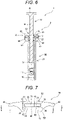
Fig. 6 is an explanatory view for explaining operation of the syringe illustrated inFig. 1 . -
Fig. 7 is a front view of a syringe barrel grip used in the syringe ofFig. 1 . -
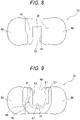
Fig. 8 is a plan view of the syringe barrel grip used in the syringe ofFig. 1 . -
Fig. 9 is a bottom view of the syringe barrel grip used in the syringe ofFig. 1 . -
Fig. 10 is a cross-sectional view taken along line E-E inFig. 7 . -
Fig. 11 is a cross-sectional view taken along line F-F inFig. 7 . -
Fig. 12 is a cross-sectional explanatory view corresponding toFig. 10 for explaining a process for manufacturing the syringe ofFig. 1 . -
Fig. 13 is a cross-sectional explanatory view corresponding toFig. 10 for explaining the process for manufacturing the syringe ofFig. 1 . -
Fig. 14 is a cross-sectional explanatory view corresponding toFig. 10 for explaining the process for manufacturing the syringe ofFig. 1 . -
Fig. 15 is a cross-sectional partial explanatory view corresponding toFig. 5 for explaining a syringe barrel grip according to another embodiment of the present invention. -
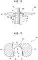
Fig. 16 is a cross-sectional partial explanatory view corresponding toFig. 5 for explaining a syringe barrel grip according to another embodiment of the present invention. -
Fig. 17 is a cross-sectional explanatory view corresponding toFig. 10 for explaining a syringe barrel grip according to another embodiment of the present invention. -
Fig. 18 is a cross-sectional explanatory view corresponding toFig. 10 for explaining a syringe barrel grip according to another embodiment of the present invention. - A syringe barrel grip of the present invention, and a barrel assembly and a syringe each including such a syringe barrel grip will be described with reference to an embodiment illustrated in the drawings.
- Note that the present embodiment will be described by defining an upper side in
Fig. 1 (the side on which aflange 22 of asyringe barrel 20 is formed) as a proximal end side or an upper side, defining a lower side inFig. 1 (the side on which anozzle portion 23 of thesyringe barrel 20 is disposed) as a distal end side or a lower side, and defining the vertical direction inFig. 1 as an axial direction (the axial direction of thesyringe barrel 20 or a cylindrical body 21). - As illustrated in
Figs. 1 to 6 , asyringe 1 of the present invention includes: abarrel assembly 2 including a syringe barrel 20 (hereinafter, also simply referred to as a barrel 20) and a syringe barrel grip 30 (hereinafter, also simply referred to as a grip 30) attached to thebarrel 20; agasket 11 slidably housed in thebarrel 20; and aplunger 12 for moving thegasket 11. - The
barrel 20 includes acylindrical body 21 and a flange 22 (thickness t) disposed in thecylindrical body 21, protruding outward (in a direction orthogonal to the axial direction of the barrel 20), and including a pair of flangestraight portions 24 and 24 (width w) facing each other in parallel. In the present embodiment, thecylindrical body 21 of thebarrel 20 has a circular (annular) outer shape and a circular (annular) inner shape in a cross section taken along a plane orthogonal to the axial direction thereof as a whole. A distal end opening portion (nozzle portion) 23 for discharging a drug is disposed at a distal end portion of thebarrel 20. - In addition, the
barrel 20 includes acollar 25 covering a proximal end side portion of thenozzle portion 23. A barrel side screwing portion (female screwing portion) is formed on an inner surface of thecollar 25. - The
nozzle portion 23 is sealed by aseal cap 13 to prevent leakage of adrug 60 stored in thebarrel 20 and to prevent the aseptically filleddrug 60 from coming into contact with outside air. - Examples of a constituent material of the
barrel 20 include various resins such as a polyolefin including polyethylene and polypropylene, polystyrene, polyamide, polycarbonate, polyvinyl chloride, poly-(4-methylpentene-1), an acrylic resin, an acrylonitrile-butadiene-styrene copolymer, a polyester including polyethylene terephthalate, a cyclic polyolefin polymer, and a cyclic olefin copolymer. Among these resins, resins such as polypropylene, a cyclic polyolefin polymer, and a cyclic olefin copolymer are preferable because the resins are easily molded and have heat resistance. Note that a cyclic olefin polymer or a cyclic olefin copolymer having high transparency such that a drug solution filled inside can be visually confirmed from the outside and having heat resistance capable of withstanding high-pressure steam sterilization is particularly preferable as a material for forming thebarrel 20. - The
seal cap 13 includes abody portion 18 having a proximal end side hollow portion that houses thenozzle portion 23 of thebarrel 20, and aseal member 19 housed in thebody portion 18 and disposed at a distal end portion of the proximal end side hollow portion. In addition, on an outer surface of the proximal end side hollow portion, a cap side screwing portion (male screwing portion) capable of being screwed with the barrel side screwing portion (female screwing portion) formed on an inner surface of thecollar 25 is formed. - Examples of a material for forming the seal cap include various resins such as polypropylene, polyethylene, polystyrene, polyamide, polycarbonate, polyvinyl chloride, poly-(4-methylpentene-1), an acrylic resin, an acrylonitrile-butadiene-styrene copolymer, a polyester including polyethylene terephthalate, and a cyclic polyolefin. Among these resins, resins such as polypropylene and a cyclic polyolefin are preferable because the resins are easily molded and have heat resistance.
- As a material for forming the
seal member 19, an elastic material such as a natural rubber, a synthetic rubber including an isoprene rubber, a butyl rubber, a butadiene rubber, a fluororubber, and a silicone rubber, or a thermoplastic elastomer including an olefin-based elastomer and a styrene-based elastomer is preferable. - The
gasket 11 housed in thebarrel 20 is made of an elastic rubber or a synthetic resin. Thegasket 11 includes a substantially cylindrical body portion extending with substantially the same outer diameter and a plurality of annular ribs disposed on an outer surface of the body portion. Outer surfaces of the annular ribs are in liquid-tight contact with an inner surface of thebarrel 20 and are slidable in a liquid-tight state. - As a material for forming the
gasket 11, it is preferable to use an elastic rubber (for example, a butyl rubber, a latex rubber, or a silicone rubber), a synthetic resin (for example, a styrene-based elastomer such as an SBS elastomer or an SEBS elastomer, or an olefin-based elastomer such as an ethylene-a olefin copolymer elastomer), or the like. - The
plunger 12 is made of a hard or semi-hard resin. In this embodiment, theplunger 12 includes a small disk-shapedgasket pressing portion 14 disposed at a distal end thereof, a disk-shapedpressing operation portion 15 disposed at a proximal end thereof, and ashaft portion 16 having a cross-shaped cross section and extending in the axial direction of thebarrel 20 between thegasket pressing portion 14 and thepressing operation portion 15. Note that theshaft portion 16 may be a columnar shaft. The columnar shaft may have a rod shape, a circular columnar shape, a polygonal columnar shape, a circular cylindrical shape, a polygonal cylindrical shape, or the like. - In this embodiment, the
plunger 12 is not connected to thegasket 11, and can abut on a proximal end portion of thegasket 11 at thegasket pressing portion 14. Thegasket 11 can be moved to a distal end side by pressing after abutment. - A distal end side portion (the
gasket pressing portion 14 and a part of a distal end side of the shaft portion 16) of theplunger 12 is housed in the barrel 20 (cylindrical body 21). Theplunger 12 includes astopper portion 17 that is disposed in a portion (shaft portion 16) housed in thebarrel 20, abuts on the grip 30 (stopper abutment portion 31) described in detail later, and restricts detachment of theplunger 12 from thebarrel 20. More specifically, thestopper portion 17 has a disk shape having an outer shape (outer diameter) smaller than the inner shape (inner diameter) of the barrel 20 (cylindrical body 21) and larger than the outer shape (maximum diameter portion) of theshaft portion 16 of theplunger 12. - As a constituent material of the
plunger 12, a hard or semi-hard resin such as high-density polyethylene, polypropylene, polystyrene, or polyethylene terephthalate is preferably used. - In the
syringe 1, the drug (drug solution) 60 is stored (filled) in the barrel 20 (in a space formed between theseal cap 13 and the gasket 11). - The
drug 60 to be stored is not particularly limited, and examples thereof include a vitamin, a sugar, an electrolyte, an organic acid, a mineral, a fat emulsion, an amino acid, a protein, and an organ preparation mainly as nutrients. Examples thereof further include a drug for a central nervous system, such as a general anesthetic, an antipyretic analgesic, or a general cold preparation, a drug for a peripheral nervous system, such as a local anesthetic or a muscle relaxant, a drug for a sensory organ, such as an ophthalmic agent, a metabolic drug such as a circulatory drug, a respiratory drug, a digestive drug, an urogenital anal drug, a hormonal agent, an antibiotic, or a diabetes drug, a biological preparation such as an antitumor drug, an allergic drug, an antibacterial agent, or an antiviral agent, and a prescription drug such as distilled water or physiological saline mainly as therapeutic agents. Examples thereof further include a vaccine mainly as a preventive agent and a contrast agent mainly as a diagnostic agent. - Many of the exemplified drugs each contain, as a main component, a synthetic low molecular weight compound, a synthetic middle molecular weight compound, a biopharmaceutical such as a polypeptide preparation or a protein preparation, or a biologically derived pharmaceutical such as a blood preparation, but these substances can be used as drugs regardless of the applications described above. In addition, a substance corresponding to a molecular target drug such as an antibody can also be used as a drug. A dosage form of each of these drugs is preferably a liquid even in a drug having a solid dosage form such as a powder or a granule in addition to a liquid from a viewpoint of usability.
- In addition, as the
drug 60, an ophthalmic drug that can be administered by puncture can be used. Examples of a specific target disease for which such an ophthalmic drug is used include choroidal neovascularization, age-related macular degeneration (both exudative and atrophic), macular edema secondary to retinal vein occlusion (RVO) (including both branch retinal vein occlusion (bRVO) and central retinal vein occlusion (cRVO)), choroidal neovascularization secondary to pathologic myopia (PM), diabetic macular edema (DME), diabetic retinopathy, and proliferative retinopathy. Examples of the drug to be used include ranibizumab [trade name: LUCENTIS (registered trademark)], bevacizumab [trade name: AVASTIN (registered trademark)], and aflibercept [trade name: EYLEA (registered trademark)], which are anti-VEGF antibodies used as therapeutic agents for age-related macular degeneration, and conbercept known as VEGF-TrapEye (aflibercept intravitreal injection solution). - The structure of the
syringe barrel grip 30 of the present invention will be described with reference to the embodiment illustrated inFigs. 1 to 14 . - The
syringe barrel grip 30 of this embodiment includes aflange housing portion 32 that houses theflange 22. As illustrated inFig. 2 , theflange housing portion 32 includes: a side surface opening 33 formed on a side surface of thegrip 30; aflange insertion portion 34 extending in an internal direction of thegrip 30 from the side surface opening 33; and a flangerotation restricting portion 35 that communicates with theflange insertion portion 34, extends into thegrip 30, and restricts relative rotation between thegrip 30 and theflange 22 that has entered the flangerotation restricting portion 35 by rotating thebarrel 20 by a predetermined angle in a state where theflange 22 is housed in theflange insertion portion 34. Theflange insertion portion 34 includes a first pair of gripstraight portions straight portions 24 and 24 (width w), and the flangerotation restricting portion 35 includes a second pair of gripstraight portions straight portions 24 and 24 (width w) and is inclined with respect to the first pair of gripstraight portions - In the present embodiment, as illustrated in
Figs. 2 ,10 , and12 to 14 , at an end portion of theflange insertion portion 34 on the flangerotation restricting portion 35 side, aprotrusion 38 that abuts on the flange 22 (flange straight portion 24) when thebarrel 20 is rotated and theflange 22 is caused to enter the flangerotation restricting portion 35 is formed. As illustrated inFig. 10 , in thegrip 30, at an end portion of the left first grip straight portion 36 (inFig. 10 ) of theflange insertion portion 34 on the flangerotation restricting portion 35 side (a connecting portion between the left first gripstraight portion 36 and the left second grip straight portion 37), theprotrusion 38 is formed. In addition, as illustrated inFig. 10 , between the right first grip straight portion 36 (inFig. 10 ) and the right second gripstraight portion 37, a steppedportion 39 which is continuous to the first gripstraight portion 36 at a right angle and connects the first gripstraight portion 36 and the second gripstraight portion 37 to each other is formed. - As illustrated in
Figs. 2 and14 , in thegrip 30, in a state where theflange 22 is housed in the flangerotation restricting portion 35, front sides of the pair of flangestraight portions straight portions 37 and 37 (between the second pair of gripstraight portions 37 and 37), and rear sides of the pair of flangestraight portions straight portions 36 and 36 (between the first pair of gripstraight portions 36 and 36). - Furthermore, in this embodiment, one rear end portion of the pair of flange
straight portions 24 and 24 (an end portion of theflange 22 on a rear side in an insertion direction into the grip 30) abuts on or approaches one of the first pair of gripstraight portions Figs. 2 and14 , inFigs. 2 and14 , a rear end portion of the right flangestraight portion 24 abuts on or approaches the right first gripstraight portion 36. As a result, theflange 22 housed in the flangerotation restricting portion 35 is prevented from moving (rattling) along the second pair of gripstraight portions rotation restricting portion 35. - As illustrated in
Figs. 3 and 4 , in thegrip 30, in a state where theflange 22 of thebarrel 20 is housed in the flangerotation restricting portion 35 of thegrip 30, a lower inner peripheral surface of thegrip 30 is not in contact with thebarrel 20, and there is agap 40 for allowing a sterilization gas to flow between the lower inner peripheral surface of thegrip 30 and thebarrel 20. - More specifically, as illustrated in
Fig. 7 , theflange housing portion 32 includes anupper plate portion 41 covering a proximal end side surface of theflange 22 and alower plate portion 42 covering a distal end side surface of theflange 22. As illustrated inFigs. 5 and7 , a distance T between theupper plate portion 41 and thelower plate portion 42 of theflange housing portion 32 is larger than the thickness t of theflange 22. As a result, a gap for allowing a sterilization gas to flow is formed between theupper plate portion 41 and the proximal end side surface of theflange 22 and/or between thelower plate portion 42 and the distal end side surface of theflange 22. - As illustrated in
Fig. 8 , an upper slit (opening) 43 is formed in theupper plate portion 41 of theflange housing portion 32. Theupper slit 43 communicates with the side surface opening 33, theflange insertion portion 34, and the flangerotation restricting portion 35 of theflange housing portion 32, and is formed such that theshaft portion 16 of theplunger 12 can enter theupper slit 43. A part of an inner edge portion of theupper slit 43 is astopper abutment portion 31 that protrudes inward and abuts on thestopper portion 17 of theplunger 12. - As a result, the
upper slit 43 allows theshaft portion 16 of theplunger 12 to pass therethrough, and abuts on thestopper portion 17 of theplunger 12 at thestopper abutment portion 31. Therefore, as illustrated inFig. 6 , theplunger 12 housed in thebarrel 20 abuts on thestopper abutment portion 31 of thegrip 30 at thestopper portion 17, whereby detachment of theplunger 12 from thebarrel 20 is restricted. - As illustrated in
Figs. 9 and10 , a lower slit (opening) 44 is formed in thelower plate portion 42 of theflange housing portion 32. Thelower slit 44 communicates with the side surface opening 33, theflange insertion portion 34, and the flangerotation restricting portion 35 of theflange housing portion 32, and is formed such that thecylindrical body 21 ofbarrel 20 can enter thelower slit 44. More specifically, the lower plate portion 42 (lower slit 44) includes abarrel insertion portion 46 including a pair of lowerstraight portions lower slit 44 and narrower than the width w of the pair of flangestraight portions straight portions - As illustrated in
Fig. 11 , the lower plate portion 42 (lower slit 44) includes abarrel housing portion 47 that communicates with thebarrel insertion portion 46, and partially surrounds the barrel 20 (cylindrical body 21) (houses the barrel 20) in a state where theflange 22 is housed in the flangerotation restricting portion 35. Thebarrel housing portion 47 has an inner shape (inner diameter, radius R illustrated inFig. 11 ) larger than the outer shape (outer diameter, radius r illustrated inFig. 3 ) of the barrel 20 (cylindrical body 21) housed therein. As a result, as illustrated inFig. 3 , in a state where theflange 22 is housed in the flangerotation restricting portion 35 of thegrip 30, an inner peripheral surface of thebarrel housing portion 47 is not in contact with thebarrel 20, and thegap 40 for allowing a sterilization gas to flow between the inner peripheral surface of thebarrel housing portion 47 and thebarrel 20 is formed. That is, in thegrip 30, on an inner peripheral surface of thelower plate portion 42 of the flange housing portion 32 (thebarrel housing portion 47 of the lower slit 44), at least a part of a lower inner peripheral surface of thegrip 30 is formed. - Note that, as illustrated in
Figs. 7 and10 , arecess 48 is formed in an upper inner edge portion of thelower plate portion 42. As a result, a sterilization gas can be brought into contact with a wider area of a distal end side surface of theflange 22 facing thelower plate portion 42. - In the
flange housing portion 32 of thegrip 30, a pair offinger hook portions grip 30 and to protrude outward (in a direction orthogonal to the axial direction of the barrel 20). The pair offinger hook portions barrel 20. The pair offinger hook portions flange 22 of thebarrel 20. The pair offinger hook portions syringe 1. - As illustrated in
Figs. 5 and7 , thegrip 30 of the present embodiment includes aside wall portion 50 extending to an axial distal end side from theflange housing portion 32. Theside wall portion 50 is integrated with (connected to) an inner edge portion of thelower slit 44 of thelower plate portion 42 of theflange housing portion 32 at a proximal end thereof. As illustrated inFig. 7 , the outer shape of theside wall portion 50 increases toward a proximal end side (flange housing portion 32 side), and is smoothly connected to thefinger hook portions flange housing portion 32. As a result, theside wall portion 50 contributes to improvement in operability of thesyringe 1. - An inner peripheral surface of the
side wall portion 50 is formed by extending an inner peripheral surface of thelower slit 44 in the axial direction over the entire length in the axial direction, and has a semi-cylindrical shape with a substantially U-shaped cross section as a whole. In theside wall portion 50, an opening for insertion extending over the entire length in the axial direction (for insertion of a proximal end portion of the cylindrical body 21) (insertion slit) 51 is formed. In a state where theflange 22 of thebarrel 20 is housed in the flangerotation restricting portion 35 of thegrip 30, an inner peripheral surface of theside wall portion 50 is not in contact with thebarrel 20, and a gap for allowing a sterilization gas to flow between the inner peripheral surface of theside wall portion 50 and the barrel 20 (thegap 40 and a gap continuous with the gap 40) is formed. In other words, theside wall portion 50 partially covers a proximal end portion of thecylindrical body 21 adjacent to theflange 22, and at least a part of the inner peripheral surface constitutes a lower inner peripheral surface of thegrip 30 that forms a gap for allowing a sterilization gas to flow between the inner peripheral surface and thebarrel 20. - Preferable examples of a constituent material of the
grip 30 include a hard or semi-hard resin such as a polyolefin including polyethylene and polypropylene, polystyrene, polyamide, polycarbonate, polyvinyl chloride, poly-(4-methylpentene-1), an acrylic resin, an acrylonitrile-butadiene-styrene copolymer, a polyester including polyethylene terephthalate, a cyclic polyolefin polymer, or a cyclic olefin copolymer. - Note that, as a constituent material of the
grip 30, a material having a thermal expansion coefficient (linear thermal expansion coefficient) larger than that of thebarrel 20 may be used. As a result, when thesyringe 1 is heated in a surface sterilization (gas sterilization) step described later, an inner surface (inner diameter) of thegrip 30 expands more than an outer surface (outer diameter) of the barrel 20 (cylindrical body 21), a gap is formed or expanded between the inner surface of thegrip 30 and the outer surface of thecylindrical body 21, and a sterilization gas enters the gap, whereby sterilizability of thesyringe 1 can be improved. - A method (process) for manufacturing such a
syringe 1 will be described. - First, the
barrel 20 is sterilized with theseal cap 13 attached to thenozzle portion 23 of thebarrel 20. Note that a sterilization method adopted at this time is not particularly limited, and for example, an autoclave sterilization method using an autoclave (high temperature steam sterilization method), a surface sterilization method using a sterilization gas such as hydrogen peroxide or EOG (gas sterilization method), or a radiation sterilization method by radiation irradiation using a y ray, an electron radiation, or the like can be used. Here, as an example, autoclave sterilization is performed. - Subsequently, under a sterile environment, the
drug 60 that has been previously subjected to sterilization treatment (for example, filtration sterilization) is aseptically filled in the sterilizedbarrel 20. In the present embodiment, thedrug 60 for ophthalmic use, which is relatively vulnerable to heat, is filled. After thedrug 60 is filled, thegasket 11 is inserted into thebarrel 20. Thegasket 11 can be inserted (capped) in a depressurized state. - Subsequently, a distal end side portion of the
plunger 12 is housed in thebarrel 20, and thegrip 30 is attached to thebarrel 20. Note that this operation can also be performed under an environment other than a sterile environment. - A step of attaching the
grip 30 to thebarrel 20 will be described in detail with reference toFigs. 12 to 14 . - First, as illustrated in
Fig. 12 , in a state where the pair of flangestraight portions barrel 20 and the first pair of gripstraight portions grip 30 are substantially parallel to each other, theflange 22 of thebarrel 20 is inserted into thegrip 30 from the side surface opening 33, and theflange 22 is housed in theflange insertion portion 34. - Subsequently, in a state where the
flange 22 is housed in theflange insertion portion 34, thebarrel 20 is biased in a rotational direction (here, counterclockwise) and rotated. During the rotation of thebarrel 20, as illustrated inFig. 13 , one (here, the left flangestraight portion 24 inFig. 13 ) of the pair of flangestraight portions protrusion 38, and a rear end portion of the other (here, the right flangestraight portion 24 inFig. 13 ) or a portion in the vicinity thereof abuts on the right first gripstraight portion 36 inFig. 13 [the grip 30 (flange housing portion 32) and barrel 20 (flange 22) are temporarily engaged with each other (first engagement state)]. - When the
barrel 20 is further biased in the rotational direction from the state where thegrip 30 and thebarrel 20 are engaged with each other, theupper slit 43, thelower slit 44, and the insertion slit 51 are formed in the grip 30 (theflange housing portion 32 and the side wall portion 50), and therefore theflange housing portion 32 of thegrip 30 is elastically deformed and pushed out. As a result, the rotation of thebarrel 20 is allowed, the engagement state between the barrel 20 (flange 22) and the grip 30 (flange housing portion 32) is released, and theflange 22 enters the flangerotation restricting portion 35. That is, thegrip 30 is temporarily engaged with thebarrel 20 when theflange 22 is caused to enter the flangerotation restricting portion 35 by rotating thebarrel 20 by a predetermined angle in a state where theflange 22 is housed in theflange insertion portion 34. - As illustrated in
Fig. 14 , when theflange 22 is housed in the flange rotation restricting portion 35 (thegrip 30 is attached to the barrel 20), thegrip 30 returns to the original state by an elastic restoring force. By causing theflange 22 to enter the flangerotation restricting portion 35, the attachment of thegrip 30 to thebarrel 20 is completed. In a state where theflange 22 is housed in the flangerotation restricting portion 35, the pair of flangestraight portions straight portions barrel 20 and thegrip 30 is restricted. - Note that, although not illustrated, when the
barrel 20 is biased in a rotational direction (here, clockwise) opposite to the rotational direction when theflange 22 is caused to enter the flangerotation restricting portion 35 in a state where thegrip 30 is attached, one (here, the left flangestraight portion 24 inFig. 14 ) of the pair of flangestraight portions protrusion 38, and a front end portion of the other (here, the right flangestraight portion 24 inFig. 14 ) or a portion in the vicinity thereof abuts on the right second gripstraight portion 37 inFig. 14 [the grip 30 (flange housing portion 32) and barrel 20 (flange 22) are temporarily engaged with each other (second engagement state)]. Therefore, it is possible to prevent thegrip 30 attached to thebarrel 20 from unintentionally falling off. In other words, since thegrip 30 is temporarily engaged with the barrel 20 (the first engagement state exists) when theflange 22 is caused to enter the flangerotation restricting portion 35 by rotating thebarrel 20 by a predetermined angle in a state where theflange 22 is housed in theflange insertion portion 34, the second engagement state occurs in theflange 22 once housed in the flangepivoting restriction portion 35, and detachment of thegrip 30 from thebarrel 20 after attachment can be prevented. - Subsequently, the
syringe 1 with thegrip 30 attached to thebarrel 20 is sterilized. In the present embodiment, since thedrug 60 stored in thebarrel 20 is a drug for ophthalmic use, which is relatively vulnerable to heat, surface sterilization (NO2 sterilization) using a sterilization gas (here, NO2 (nitrogen dioxide)) is performed. - As described above, the
syringe 1 can be aseptically manufactured. - The grip 30 (flange housing portion 32) of the present embodiment includes the flange
rotation restricting portion 35 including the second pair of gripstraight portions straight portions flange insertion portion 34, and in a state where theflange 22 is stored in the flangerotation restricting portion 35, a part of the pair of flangestraight portions straight portions grip 30 is restricted in a state where thegrip 30 is attached to thesyringe barrel 20, and therefore operability is good. - Furthermore, in the
grip 30 of the present embodiment, in a state where theflange 22 of thebarrel 20 is housed in the flangerotation restricting portion 35 of thegrip 30, a lower inner peripheral surface of the grip 30 (an inner peripheral surface of thelower slit 44 of thelower plate portion 42 and/or an inner peripheral surface of the side wall portion 50) is not in contact with thebarrel 20, and there is agap 40 for allowing a sterilization gas to flow between the lower inner peripheral surface of thegrip 30 and thebarrel 20. Therefore, the sterilization gas can be brought into contact with a wider area of surfaces of thegrip 30 and thebarrel 20, and thesyringe barrel grip 30 and thesyringe barrel 20 to which such agrip 30 is attached are more reliably sterilized. - Note that, in the present embodiment, the
cylindrical body 21 of thebarrel 20 has a circular cylindrical shape in which the cross sections of the outer shape and the inner shape are substantially circular, but the present invention is not limited thereto. It is possible to appropriately use those having various cylindrical shapes in which the cross sections are elliptical, polygonal, and the like, those having different cross-sectional shapes between the outer shape and the inner shape, and the like, and the shape of the grip 30 (flange housing portion 32) can also be appropriately changed accordingly. - In addition, as in a
grip 30a illustrated inFig. 15 , the side wall portion (50) does not have to be disposed. In thegrip 30a, alower plate portion 42a of aflange housing portion 32a constitutes a most distal end portion (lowest portion) of thegrip 30a. As a result, thegrip 30a can be further reduced in size and weight. - In a
grip 30b illustrated inFig. 16 , alower plate portion 42b of aflange housing portion 32b is thicker than thegrip 30a (lower plate portion 42a) described above. As a result, the strength of thegrip 30b can be increased. In thegrip 30b, as illustrated inFig. 16 , an inner peripheral surface (inner shape) of thelower plate portion 42b (abarrel housing portion 47b of alower slit 44b) expands downward. As a result, a flow of a sterilization gas between thegrip 30b and thebarrel 20 is further promoted while the strength of thegrip 30b is increased by thickening thelower plate portion 42b, and the sterilization is more reliably performed. - In addition, as in a
grip 30c illustrated inFig. 17 , a right first gripstraight portion 36c and a right second gripstraight portion 37c inFig. 17 in aflange housing portion 32c may be connected to each other as they are without forming the stepped portion (39). - In addition, as in a
grip 30d illustrated inFig. 18 , a right first gripstraight portion 36d and a right second gripstraight portion 37d inFig. 18 in aflange housing portion 32d may be connected to each other at a gentle angle with an inclined steppedportion 39d. - In addition, although not illustrated, the
protrusion 38 formed in theflange housing portion 32 is not limited to the exemplified one. For example, theprotrusion 38 may be formed so as to protrude from the first gripstraight portion 36 toward the inside of theflange housing portion 32, and as for a formation portion thereof, theprotrusion 38 may be formed at a middle portion of the first gripstraight portion 36 instead of the end portion of the first gripstraight portion 36 on the flangerotation restricting portion 35 side. - The syringe barrel grip of the present invention is as follows.
- (1) A syringe barrel grip attached to a syringe barrel including a cylindrical body and a flange disposed in the cylindrical body, protruding outward, and including a pair of flange straight portions facing each other in parallel,
- the grip including a flange housing portion that houses the flange, in which
- the flange housing portion includes: a side surface opening formed on a side surface of the grip; a flange insertion portion extending in an internal direction of the grip from the side surface opening; and a flange rotation restricting portion that communicates with the flange insertion portion, extends into the grip, and restricts relative rotation between the grip and the flange that has entered the flange rotation restricting portion by rotating the barrel by a predetermined angle in a state where the flange is housed in the flange insertion portion,
- the flange insertion portion includes a first pair of grip straight portions having a slightly wider width than the pair of flange straight portions, and the flange rotation restricting portion includes a second pair of grip straight portions having a slightly wider width than the pair of flange straight portions and is inclined with respect to the first pair of grip straight portions,
- in a state where the flange is housed in the flange rotation restricting portion, front sides of the pair of flange straight portions are located in the second pair of grip straight portions, and rear sides of the pair of flange straight portions are located in the first pair of grip straight portions, and
- in a state where the flange of the barrel is housed in the flange rotation restricting portion of the grip, a lower inner peripheral surface of the grip is not in contact with the barrel, and there is a gap for allowing a sterilization gas to flow between the lower inner peripheral surface of the grip and the barrel.
- The syringe barrel grip of the present invention is attached to a syringe barrel including a cylindrical body and a flange disposed in the cylindrical body, protruding outward, and including a pair of flange straight portions facing each other in parallel. The grip of the present invention includes a flange housing portion that houses a flange, and the flange housing portion includes: a side surface opening formed on a side surface of the grip; a flange insertion portion extending in an internal direction of the grip from the side surface opening; and a flange rotation restricting portion that communicates with the flange insertion portion, extends into the grip, and restricts relative rotation between the grip and the flange that has entered the flange rotation restricting portion by rotating the barrel by a predetermined angle in a state where the flange is housed in the flange insertion portion.
- Furthermore, the flange insertion portion of the grip of the present invention includes a first pair of grip straight portions having a slightly wider width than the pair of flange straight portions, the flange rotation restricting portion includes a second pair of grip straight portions having a slightly wider width than the pair of flange straight portions and is inclined with respect to the first pair of grip straight portions, and in a state where the flange is housed in the flange rotation restricting portion, front sides of the pair of flange straight portions are located in the second pair of grip straight portions, and rear sides of the pair of flange straight portions are located in the first pair of grip straight portions.
- Therefore, in the syringe barrel grip, the barrel assembly, and the syringe of the present invention, relative rotation between the flange and the grip is restricted in a state where the grip is attached to the syringe barrel, and therefore operability is good.
- Furthermore, in the grip of the present invention, in a state where the flange of the barrel is housed in the flange rotation restricting portion of the grip, a lower inner peripheral surface of the grip is not in contact with the barrel, and there is a gap for allowing a sterilization gas to flow between the lower inner peripheral surface of the grip and the barrel.
- Therefore, in the syringe barrel grip, the barrel assembly, and the syringe of the present invention, the sterilization gas can be brought into contact with a wider area of surfaces of the grip and the barrel, and the syringe barrel grip and a syringe barrel to which such a grip is attached are more reliably sterilized.
- In addition, the above embodiment may be as follows.
- (2) The syringe barrel grip according to (1), in which the grip includes a side wall portion partially covering a proximal end portion of the cylindrical body adjacent to the flange, and at least a part of an inner peripheral surface of the side wall portion is the lower inner peripheral surface.
- (3) The syringe barrel grip according to (1) or (2), in which the grip is temporarily engaged with the barrel when the flange is caused to enter the flange rotation restricting portion by rotating the barrel by a predetermined angle in a state where the flange is housed in the flange insertion portion.
- (4) The syringe barrel grip according to any one of (1) to (3), in which the flange housing portion includes an upper plate portion covering a proximal end side surface of the flange and a lower plate portion covering a distal end side surface of the flange, a distance between the upper plate portion and the lower plate portion is larger than the thickness of the flange, and a gap for allowing a sterilization gas to flow is formed between the upper plate portion and the proximal end side surface of the flange and/or between the lower plate portion and the distal end side surface of the flange.
- The barrel assembly of the present invention is as follows.
- (5) A barrel assembly including: a syringe barrel including a cylindrical body and a flange disposed at a proximal end of the cylindrical body, protruding outward, and including a pair of flange straight portions facing each other in parallel; and the syringe barrel grip according to any one of (1) to (4) attached to the barrel.
- The barrel assembly of the present invention includes a syringe barrel grip attached to a syringe barrel including a cylindrical body and a flange disposed in the cylindrical body, protruding outward, and including a pair of flange straight portions facing each other in parallel. The grip includes a flange housing portion that houses a flange, and the flange housing portion includes: a side surface opening formed on a side surface of the grip; a flange insertion portion extending in an internal direction of the grip from the side surface opening; and a flange rotation restricting portion that communicates with the flange insertion portion, extends into the grip, and restricts relative rotation between the grip and the flange that has entered the flange rotation restricting portion by rotating the barrel by a predetermined angle in a state where the flange is housed in the flange insertion portion.
- Furthermore, the flange insertion portion of the grip includes a first pair of grip straight portions having a slightly wider width than the pair of flange straight portions, the flange rotation restricting portion includes a second pair of grip straight portions having a slightly wider width than the pair of flange straight portions and is inclined with respect to the first pair of grip straight portions, and in a state where the flange is housed in the flange rotation restricting portion, front sides of the pair of flange straight portions are located in the second pair of grip straight portions, and rear sides of the pair of flange straight portions are located in the first pair of grip straight portions.
- Therefore, in the barrel assembly of the present invention, relative rotation between the flange and the grip is restricted in a state where the grip is attached to the syringe barrel, and therefore operability is good.
- Furthermore, in the barrel assembly of the present invention, in a state where the flange of the barrel is housed in the flange rotation restricting portion of the grip, a lower inner peripheral surface of the grip is not in contact with the barrel, and there is a gap for allowing a sterilization gas to flow between the lower inner peripheral surface of the grip and the barrel.
- Therefore, in the barrel assembly of the present invention, the sterilization gas can be brought into contact with a wider area of surfaces of the grip and the barrel, and the syringe barrel grip and a syringe barrel to which such a grip is attached are more reliably sterilized.
- The syringe of the present invention is as follows.
- (6) A syringe including: the barrel assembly according to (5); a gasket slidably housed in the barrel; and a plunger for moving the gasket.
- The syringe of the present invention includes a syringe barrel grip attached to a syringe barrel including a cylindrical body and a flange disposed in the cylindrical body, protruding outward, and including a pair of flange straight portions facing each other in parallel. The grip includes a flange housing portion that houses a flange, and the flange housing portion includes: a side surface opening formed on a side surface of the grip; a flange insertion portion extending in an internal direction of the grip from the side surface opening; and a flange rotation restricting portion that communicates with the flange insertion portion, extends into the grip, and restricts relative rotation between the grip and the flange that has entered the flange rotation restricting portion by rotating the barrel by a predetermined angle in a state where the flange is housed in the flange insertion portion.
- Furthermore, the flange insertion portion of the grip includes a first pair of grip straight portions having a slightly wider width than the pair of flange straight portions, the flange rotation restricting portion includes a second pair of grip straight portions having a slightly wider width than the pair of flange straight portions and is inclined with respect to the first pair of grip straight portions, and in a state where the flange is housed in the flange rotation restricting portion, front sides of the pair of flange straight portions are located in the second pair of grip straight portions, and rear sides of the pair of flange straight portions are located in the first pair of grip straight portions.
- Therefore, in the syringe of the present invention, relative rotation between the flange and the grip is restricted in a state where the grip is attached to the syringe barrel, and therefore operability is good.
- Furthermore, in the syringe of the present invention, in a state where the flange of the barrel is housed in the flange rotation restricting portion of the grip, a lower inner peripheral surface of the grip is not in contact with the barrel, and there is a gap for allowing a sterilization gas to flow between the lower inner peripheral surface of the grip and the barrel.
- Therefore, in the syringe of the present invention, the sterilization gas can be brought into contact with a wider area of surfaces of the grip and the barrel, and the syringe barrel grip and a syringe barrel to which such a grip is attached are more reliably sterilized.
- In addition, the above embodiment may be as follows.
- (7) The syringe according to (6), in which a distal end side portion of the plunger is housed in the barrel, and the plunger includes a stopper portion that is disposed in a portion housed in the barrel, abuts on the grip, and restricts detachment of the plunger from the barrel.
- (8) The syringe according to (6) or (7), in which the plunger is not connected to the gasket and includes a gasket pressing portion that abuts on a proximal end portion of the gasket at a distal end thereof.
- (9) The syringe according to any one of (6) to (8), in which a drug is stored in the barrel.
Claims (9)
- A syringe barrel grip attached to a syringe barrel including a cylindrical body and a flange disposed in the cylindrical body, protruding outward, and including a pair of flange straight portions facing each other in parallel,the grip comprising a flange housing portion that houses the flange, whereinthe flange housing portion includes: a side surface opening formed on a side surface of the grip; a flange insertion portion extending in an internal direction of the grip from the side surface opening; and a flange rotation restricting portion that communicates with the flange insertion portion, extends into the grip, and restricts relative rotation between the grip and the flange that has entered the flange rotation restricting portion by rotating the barrel by a predetermined angle in a state where the flange is housed in the flange insertion portion,the flange insertion portion includes a first pair of grip straight portions having a slightly wider width than the pair of flange straight portions, and the flange rotation restricting portion includes a second pair of grip straight portions having a slightly wider width than the pair of flange straight portions and is inclined with respect to the first pair of grip straight portions,in a state where the flange is housed in the flange rotation restricting portion, front sides of the pair of flange straight portions are located in the second pair of grip straight portions, and rear sides of the pair of flange straight portions are located in the first pair of grip straight portions, andin a state where the flange of the barrel is housed in the flange rotation restricting portion of the grip, a lower inner peripheral surface of the grip is not in contact with the barrel, and there is a gap for allowing a sterilization gas to flow between the lower inner peripheral surface of the grip and the barrel.
- The syringe barrel grip according to claim 1, wherein the grip includes a side wall portion partially covering a proximal end portion of the cylindrical body adjacent to the flange, and at least a part of an inner peripheral surface of the side wall portion is the lower inner peripheral surface.
- The syringe barrel grip according to claim 1 or 2, wherein the grip is temporarily engaged with the barrel when the flange is caused to enter the flange rotation restricting portion by rotating the barrel by a predetermined angle in a state where the flange is housed in the flange insertion portion.
- The syringe barrel grip according to any one of claims 1 to 3, wherein the flange housing portion includes an upper plate portion covering a proximal end side surface of the flange and a lower plate portion covering a distal end side surface of the flange, a distance between the upper plate portion and the lower plate portion is larger than a thickness of the flange, and a gap for allowing a sterilization gas to flow is formed between the upper plate portion and the proximal end side surface of the flange and/or between the lower plate portion and the distal end side surface of the flange.
- A barrel assembly comprising: a syringe barrel including a cylindrical body and a flange disposed at a proximal end of the cylindrical body, protruding outward, and including a pair of flange straight portions facing each other in parallel; and the syringe barrel grip according to any one of claims 1 to 4 attached to the barrel.
- A syringe comprising: the barrel assembly according to claim 5; a gasket slidably housed in the barrel; and a plunger for moving the gasket.
- The syringe according to claim 6, wherein a distal end side portion of the plunger is housed in the barrel, and the plunger includes a stopper portion that is disposed in a portion housed in the barrel, abuts on the grip, and restricts detachment of the plunger from the barrel.
- The syringe according to claim 6 or 7, wherein the plunger is not connected to the gasket and includes a gasket pressing portion that abuts on a proximal end portion of the gasket at a distal end thereof.
- The syringe according to any one of claims 6 to 8, wherein a drug is stored in the barrel.
Applications Claiming Priority (2)
| Application Number | Priority Date | Filing Date | Title |
|---|---|---|---|
| JP2020052233 | 2020-03-24 | ||
| PCT/JP2021/003898 WO2021192637A1 (en) | 2020-03-24 | 2021-02-03 | Syringe-barrel grip, barrel assembly, and syringe |
Publications (3)
| Publication Number | Publication Date |
|---|---|
| EP4098298A1 true EP4098298A1 (en) | 2022-12-07 |
| EP4098298A4 EP4098298A4 (en) | 2023-07-19 |
| EP4098298B1 EP4098298B1 (en) | 2025-08-27 |
Family
ID=77891383
Family Applications (1)
| Application Number | Title | Priority Date | Filing Date |
|---|---|---|---|
| EP21776305.1A Active EP4098298B1 (en) | 2020-03-24 | 2021-02-03 | Syringe-barrel grip, barrel assembly, and syringe |
Country Status (5)
| Country | Link |
|---|---|
| US (1) | US12502484B2 (en) |
| EP (1) | EP4098298B1 (en) |
| JP (1) | JP7488331B2 (en) |
| CN (1) | CN114929311B (en) |
| WO (1) | WO2021192637A1 (en) |
Families Citing this family (2)
| Publication number | Priority date | Publication date | Assignee | Title |
|---|---|---|---|---|
| CN119604320A (en) * | 2022-07-07 | 2025-03-11 | 泰尔茂欧洲有限公司 | Finger grip |
| JP7824616B1 (en) * | 2025-09-08 | 2026-03-05 | 慶太 古宮 | Syringe Adapter |
Family Cites Families (12)
| Publication number | Priority date | Publication date | Assignee | Title |
|---|---|---|---|---|
| JP2004097277A (en) * | 2002-09-05 | 2004-04-02 | Arute:Kk | Auxiliary grip for container / syringe |
| JP2004313369A (en) * | 2003-04-15 | 2004-11-11 | Menicon Co Ltd | Cartridge injector, cartridge and ophthalmic injector set equipped with the injector |
| WO2013038887A1 (en) * | 2011-09-14 | 2013-03-21 | テルモ株式会社 | Liquid injection device |
| PT3858405T (en) | 2012-06-01 | 2023-06-26 | Novartis Ag | Syringe |
| DE202013000688U1 (en) | 2012-07-03 | 2013-03-05 | Novartis Ag | Glass syringe |
| JP2015080688A (en) * | 2013-10-24 | 2015-04-27 | 大成化工株式会社 | Fitting tool for syringe |
| US10258502B2 (en) | 2014-09-18 | 2019-04-16 | Orbit Biomedical Limited | Therapeutic agent delivery device |
| JP7030411B2 (en) * | 2015-01-19 | 2022-03-07 | 株式会社ジェイ・エム・エス | Medical fluid sampling injector |
| CN107427639B (en) * | 2015-03-24 | 2020-10-02 | 泰尔茂株式会社 | Syringe Holders and Administration Assemblies |
| WO2017039786A1 (en) * | 2015-09-02 | 2017-03-09 | Amgen Inc. | Syringe assembly adapter for a syringe |
| WO2017073658A1 (en) | 2015-10-30 | 2017-05-04 | テルモ株式会社 | Grip and syringe assembly |
| US10596321B2 (en) * | 2016-04-08 | 2020-03-24 | Allergan, Inc. | Aspiration and injection device |
-
2021
- 2021-02-03 JP JP2022509347A patent/JP7488331B2/en active Active
- 2021-02-03 CN CN202180008185.9A patent/CN114929311B/en active Active
- 2021-02-03 EP EP21776305.1A patent/EP4098298B1/en active Active
- 2021-02-03 WO PCT/JP2021/003898 patent/WO2021192637A1/en not_active Ceased
-
2022
- 2022-07-22 US US17/871,334 patent/US12502484B2/en active Active
Also Published As
| Publication number | Publication date |
|---|---|
| JP7488331B2 (en) | 2024-05-21 |
| US20220355038A1 (en) | 2022-11-10 |
| CN114929311A (en) | 2022-08-19 |
| EP4098298B1 (en) | 2025-08-27 |
| US12502484B2 (en) | 2025-12-23 |
| CN114929311B (en) | 2023-07-28 |
| JPWO2021192637A1 (en) | 2021-09-30 |
| EP4098298A4 (en) | 2023-07-19 |
| WO2021192637A1 (en) | 2021-09-30 |
Similar Documents
| Publication | Publication Date | Title |
|---|---|---|
| US20220323681A1 (en) | Grip for syringe barrel, barrel assembly, and syringe | |
| US12311149B2 (en) | Flush syringe with flip cap | |
| KR102465054B1 (en) | Solution delivery device and method | |
| JP6700177B2 (en) | Tip cap assembly for closing injection system | |
| EP1563863A1 (en) | Method of producing syringe, cap, and prefilled syringe | |
| US20090270832A1 (en) | Needleless port assembly for a container | |
| CA2235940A1 (en) | Tamper evident syringe design | |
| US12502484B2 (en) | Syringe barrel grip, barrel assembly, and syringe | |
| JP2016528996A (en) | Luer connection adapter for syringe | |
| JP2023118957A (en) | drug transfer assembly | |
| JP2011212183A (en) | Prefilled syringe | |
| JPWO2002005877A1 (en) | liquid injection equipment | |
| JP6255163B2 (en) | Drug preparation tool | |
| AU2023458478B2 (en) | System and method for butterfly needle assembly | |
| JP2003260112A (en) | Medicine blending method | |
| HK1242178A1 (en) | Solution delivery device and method | |
| JPH0654907A (en) | Injection syringe | |
| JP2001104481A (en) | Injector for prefilled syringe, and prefilled syringe |
Legal Events
| Date | Code | Title | Description |
|---|---|---|---|
| STAA | Information on the status of an ep patent application or granted ep patent |
Free format text: STATUS: THE INTERNATIONAL PUBLICATION HAS BEEN MADE |
|
| PUAI | Public reference made under article 153(3) epc to a published international application that has entered the european phase |
Free format text: ORIGINAL CODE: 0009012 |
|
| STAA | Information on the status of an ep patent application or granted ep patent |
Free format text: STATUS: REQUEST FOR EXAMINATION WAS MADE |
|
| 17P | Request for examination filed |
Effective date: 20220831 |
|
| AK | Designated contracting states |
Kind code of ref document: A1 Designated state(s): AL AT BE BG CH CY CZ DE DK EE ES FI FR GB GR HR HU IE IS IT LI LT LU LV MC MK MT NL NO PL PT RO RS SE SI SK SM TR |
|
| DAV | Request for validation of the european patent (deleted) | ||
| DAX | Request for extension of the european patent (deleted) | ||
| A4 | Supplementary search report drawn up and despatched |
Effective date: 20230620 |
|
| RIC1 | Information provided on ipc code assigned before grant |
Ipc: A61M 5/00 20060101ALN20230614BHEP Ipc: A61M 5/31 20060101AFI20230614BHEP |
|
| GRAP | Despatch of communication of intention to grant a patent |
Free format text: ORIGINAL CODE: EPIDOSNIGR1 |
|
| STAA | Information on the status of an ep patent application or granted ep patent |
Free format text: STATUS: GRANT OF PATENT IS INTENDED |
|
| RIC1 | Information provided on ipc code assigned before grant |
Ipc: A61M 5/00 20060101ALN20250407BHEP Ipc: A61M 5/31 20060101AFI20250407BHEP |
|
| INTG | Intention to grant announced |
Effective date: 20250417 |
|
| GRAS | Grant fee paid |
Free format text: ORIGINAL CODE: EPIDOSNIGR3 |
|
| GRAA | (expected) grant |
Free format text: ORIGINAL CODE: 0009210 |
|
| STAA | Information on the status of an ep patent application or granted ep patent |
Free format text: STATUS: THE PATENT HAS BEEN GRANTED |
|
| AK | Designated contracting states |
Kind code of ref document: B1 Designated state(s): AL AT BE BG CH CY CZ DE DK EE ES FI FR GB GR HR HU IE IS IT LI LT LU LV MC MK MT NL NO PL PT RO RS SE SI SK SM TR |
|
| REG | Reference to a national code |
Ref country code: CH Ref legal event code: EP |
|
| REG | Reference to a national code |
Ref country code: DE Ref legal event code: R096 Ref document number: 602021037248 Country of ref document: DE |
|
| REG | Reference to a national code |
Ref country code: IE Ref legal event code: FG4D |
|
| REG | Reference to a national code |
Ref country code: NL Ref legal event code: MP Effective date: 20250827 |
|
| PG25 | Lapsed in a contracting state [announced via postgrant information from national office to epo] |
Ref country code: IS Free format text: LAPSE BECAUSE OF FAILURE TO SUBMIT A TRANSLATION OF THE DESCRIPTION OR TO PAY THE FEE WITHIN THE PRESCRIBED TIME-LIMIT Effective date: 20251227 |
|
| PG25 | Lapsed in a contracting state [announced via postgrant information from national office to epo] |
Ref country code: NO Free format text: LAPSE BECAUSE OF FAILURE TO SUBMIT A TRANSLATION OF THE DESCRIPTION OR TO PAY THE FEE WITHIN THE PRESCRIBED TIME-LIMIT Effective date: 20251127 |
|
| REG | Reference to a national code |
Ref country code: LT Ref legal event code: MG9D |
|
| PG25 | Lapsed in a contracting state [announced via postgrant information from national office to epo] |
Ref country code: PT Free format text: LAPSE BECAUSE OF FAILURE TO SUBMIT A TRANSLATION OF THE DESCRIPTION OR TO PAY THE FEE WITHIN THE PRESCRIBED TIME-LIMIT Effective date: 20251229 |
|
| PG25 | Lapsed in a contracting state [announced via postgrant information from national office to epo] |
Ref country code: FI Free format text: LAPSE BECAUSE OF FAILURE TO SUBMIT A TRANSLATION OF THE DESCRIPTION OR TO PAY THE FEE WITHIN THE PRESCRIBED TIME-LIMIT Effective date: 20250827 |
|
| PG25 | Lapsed in a contracting state [announced via postgrant information from national office to epo] |
Ref country code: NL Free format text: LAPSE BECAUSE OF FAILURE TO SUBMIT A TRANSLATION OF THE DESCRIPTION OR TO PAY THE FEE WITHIN THE PRESCRIBED TIME-LIMIT Effective date: 20250827 Ref country code: HR Free format text: LAPSE BECAUSE OF FAILURE TO SUBMIT A TRANSLATION OF THE DESCRIPTION OR TO PAY THE FEE WITHIN THE PRESCRIBED TIME-LIMIT Effective date: 20250827 |
|
| PGFP | Annual fee paid to national office [announced via postgrant information from national office to epo] |
Ref country code: FR Payment date: 20251231 Year of fee payment: 6 |
|
| PG25 | Lapsed in a contracting state [announced via postgrant information from national office to epo] |
Ref country code: GR Free format text: LAPSE BECAUSE OF FAILURE TO SUBMIT A TRANSLATION OF THE DESCRIPTION OR TO PAY THE FEE WITHIN THE PRESCRIBED TIME-LIMIT Effective date: 20251128 |
|
| PG25 | Lapsed in a contracting state [announced via postgrant information from national office to epo] |
Ref country code: SE Free format text: LAPSE BECAUSE OF FAILURE TO SUBMIT A TRANSLATION OF THE DESCRIPTION OR TO PAY THE FEE WITHIN THE PRESCRIBED TIME-LIMIT Effective date: 20250827 |
|
| PG25 | Lapsed in a contracting state [announced via postgrant information from national office to epo] |
Ref country code: LV Free format text: LAPSE BECAUSE OF FAILURE TO SUBMIT A TRANSLATION OF THE DESCRIPTION OR TO PAY THE FEE WITHIN THE PRESCRIBED TIME-LIMIT Effective date: 20250827 |
|
| PG25 | Lapsed in a contracting state [announced via postgrant information from national office to epo] |
Ref country code: BG Free format text: LAPSE BECAUSE OF FAILURE TO SUBMIT A TRANSLATION OF THE DESCRIPTION OR TO PAY THE FEE WITHIN THE PRESCRIBED TIME-LIMIT Effective date: 20250827 Ref country code: PL Free format text: LAPSE BECAUSE OF FAILURE TO SUBMIT A TRANSLATION OF THE DESCRIPTION OR TO PAY THE FEE WITHIN THE PRESCRIBED TIME-LIMIT Effective date: 20250827 |
|
| PG25 | Lapsed in a contracting state [announced via postgrant information from national office to epo] |
Ref country code: RS Free format text: LAPSE BECAUSE OF FAILURE TO SUBMIT A TRANSLATION OF THE DESCRIPTION OR TO PAY THE FEE WITHIN THE PRESCRIBED TIME-LIMIT Effective date: 20251127 |
|
| PG25 | Lapsed in a contracting state [announced via postgrant information from national office to epo] |
Ref country code: ES Free format text: LAPSE BECAUSE OF FAILURE TO SUBMIT A TRANSLATION OF THE DESCRIPTION OR TO PAY THE FEE WITHIN THE PRESCRIBED TIME-LIMIT Effective date: 20250827 |
|
| REG | Reference to a national code |
Ref country code: AT Ref legal event code: MK05 Ref document number: 1829277 Country of ref document: AT Kind code of ref document: T Effective date: 20250827 |
|
| PG25 | Lapsed in a contracting state [announced via postgrant information from national office to epo] |
Ref country code: SM Free format text: LAPSE BECAUSE OF FAILURE TO SUBMIT A TRANSLATION OF THE DESCRIPTION OR TO PAY THE FEE WITHIN THE PRESCRIBED TIME-LIMIT Effective date: 20250827 |
|
| PGFP | Annual fee paid to national office [announced via postgrant information from national office to epo] |
Ref country code: GB Payment date: 20260106 Year of fee payment: 6 |
|
| PG25 | Lapsed in a contracting state [announced via postgrant information from national office to epo] |
Ref country code: DK Free format text: LAPSE BECAUSE OF FAILURE TO SUBMIT A TRANSLATION OF THE DESCRIPTION OR TO PAY THE FEE WITHIN THE PRESCRIBED TIME-LIMIT Effective date: 20250827 |
|
| PGFP | Annual fee paid to national office [announced via postgrant information from national office to epo] |
Ref country code: DE Payment date: 20251230 Year of fee payment: 6 |
|
| PG25 | Lapsed in a contracting state [announced via postgrant information from national office to epo] |
Ref country code: AT Free format text: LAPSE BECAUSE OF FAILURE TO SUBMIT A TRANSLATION OF THE DESCRIPTION OR TO PAY THE FEE WITHIN THE PRESCRIBED TIME-LIMIT Effective date: 20250827 |
|
| PG25 | Lapsed in a contracting state [announced via postgrant information from national office to epo] |
Ref country code: IT Free format text: LAPSE BECAUSE OF FAILURE TO SUBMIT A TRANSLATION OF THE DESCRIPTION OR TO PAY THE FEE WITHIN THE PRESCRIBED TIME-LIMIT Effective date: 20250827 |
|
| PG25 | Lapsed in a contracting state [announced via postgrant information from national office to epo] |
Ref country code: CZ Free format text: LAPSE BECAUSE OF FAILURE TO SUBMIT A TRANSLATION OF THE DESCRIPTION OR TO PAY THE FEE WITHIN THE PRESCRIBED TIME-LIMIT Effective date: 20250827 |
|
| PG25 | Lapsed in a contracting state [announced via postgrant information from national office to epo] |
Ref country code: SK Free format text: LAPSE BECAUSE OF FAILURE TO SUBMIT A TRANSLATION OF THE DESCRIPTION OR TO PAY THE FEE WITHIN THE PRESCRIBED TIME-LIMIT Effective date: 20250827 Ref country code: EE Free format text: LAPSE BECAUSE OF FAILURE TO SUBMIT A TRANSLATION OF THE DESCRIPTION OR TO PAY THE FEE WITHIN THE PRESCRIBED TIME-LIMIT Effective date: 20250827 |