EP4096207B1 - Mobiles endgerät, verfahren zum detektieren des bildaufnahmemodus und speichermedium - Google Patents
Mobiles endgerät, verfahren zum detektieren des bildaufnahmemodus und speichermedium Download PDFInfo
- Publication number
- EP4096207B1 EP4096207B1 EP21744020.5A EP21744020A EP4096207B1 EP 4096207 B1 EP4096207 B1 EP 4096207B1 EP 21744020 A EP21744020 A EP 21744020A EP 4096207 B1 EP4096207 B1 EP 4096207B1
- Authority
- EP
- European Patent Office
- Prior art keywords
- magnetic field
- field strength
- camera module
- shooting mode
- level signal
- Prior art date
- Legal status (The legal status is an assumption and is not a legal conclusion. Google has not performed a legal analysis and makes no representation as to the accuracy of the status listed.)
- Active
Links
Images

Classifications
-
- G—PHYSICS
- G01—MEASURING; TESTING
- G01V—GEOPHYSICS; GRAVITATIONAL MEASUREMENTS; DETECTING MASSES OR OBJECTS; TAGS
- G01V3/00—Electric or magnetic prospecting or detecting; Measuring magnetic field characteristics of the earth, e.g. declination, deviation
- G01V3/08—Electric or magnetic prospecting or detecting; Measuring magnetic field characteristics of the earth, e.g. declination, deviation operating with magnetic or electric fields produced or modified by objects or geological structures or by detecting devices
- G01V3/081—Electric or magnetic prospecting or detecting; Measuring magnetic field characteristics of the earth, e.g. declination, deviation operating with magnetic or electric fields produced or modified by objects or geological structures or by detecting devices the magnetic field is produced by the objects or geological structures
-
- H—ELECTRICITY
- H04—ELECTRIC COMMUNICATION TECHNIQUE
- H04M—TELEPHONIC COMMUNICATION
- H04M1/00—Substation equipment, e.g. for use by subscribers
- H04M1/02—Constructional features of telephone sets
- H04M1/0202—Portable telephone sets, e.g. cordless phones, mobile phones or bar type handsets
- H04M1/026—Details of the structure or mounting of specific components
- H04M1/0264—Details of the structure or mounting of specific components for a camera module assembly
-
- H—ELECTRICITY
- H04—ELECTRIC COMMUNICATION TECHNIQUE
- H04N—PICTORIAL COMMUNICATION, e.g. TELEVISION
- H04N23/00—Cameras or camera modules comprising electronic image sensors; Control thereof
- H04N23/45—Cameras or camera modules comprising electronic image sensors; Control thereof for generating image signals from two or more image sensors being of different type or operating in different modes, e.g. with a CMOS sensor for moving images in combination with a charge-coupled device [CCD] for still images
-
- H—ELECTRICITY
- H04—ELECTRIC COMMUNICATION TECHNIQUE
- H04N—PICTORIAL COMMUNICATION, e.g. TELEVISION
- H04N23/00—Cameras or camera modules comprising electronic image sensors; Control thereof
- H04N23/50—Constructional details
-
- H—ELECTRICITY
- H04—ELECTRIC COMMUNICATION TECHNIQUE
- H04N—PICTORIAL COMMUNICATION, e.g. TELEVISION
- H04N23/00—Cameras or camera modules comprising electronic image sensors; Control thereof
- H04N23/50—Constructional details
- H04N23/54—Mounting of pick-up tubes, electronic image sensors, deviation or focusing coils
-
- H—ELECTRICITY
- H04—ELECTRIC COMMUNICATION TECHNIQUE
- H04N—PICTORIAL COMMUNICATION, e.g. TELEVISION
- H04N23/00—Cameras or camera modules comprising electronic image sensors; Control thereof
- H04N23/57—Mechanical or electrical details of cameras or camera modules specially adapted for being embedded in other devices
-
- H—ELECTRICITY
- H04—ELECTRIC COMMUNICATION TECHNIQUE
- H04N—PICTORIAL COMMUNICATION, e.g. TELEVISION
- H04N23/00—Cameras or camera modules comprising electronic image sensors; Control thereof
- H04N23/60—Control of cameras or camera modules
- H04N23/64—Computer-aided capture of images, e.g. transfer from script file into camera, check of taken image quality, advice or proposal for image composition or decision on when to take image
-
- H—ELECTRICITY
- H04—ELECTRIC COMMUNICATION TECHNIQUE
- H04N—PICTORIAL COMMUNICATION, e.g. TELEVISION
- H04N23/00—Cameras or camera modules comprising electronic image sensors; Control thereof
- H04N23/60—Control of cameras or camera modules
- H04N23/66—Remote control of cameras or camera parts, e.g. by remote control devices
- H04N23/663—Remote control of cameras or camera parts, e.g. by remote control devices for controlling interchangeable camera parts based on electronic image sensor signals
-
- H—ELECTRICITY
- H04—ELECTRIC COMMUNICATION TECHNIQUE
- H04N—PICTORIAL COMMUNICATION, e.g. TELEVISION
- H04N23/00—Cameras or camera modules comprising electronic image sensors; Control thereof
- H04N23/60—Control of cameras or camera modules
- H04N23/667—Camera operation mode switching, e.g. between still and video, sport and normal or high- and low-resolution modes
-
- G—PHYSICS
- G03—PHOTOGRAPHY; CINEMATOGRAPHY; ANALOGOUS TECHNIQUES USING WAVES OTHER THAN OPTICAL WAVES; ELECTROGRAPHY; HOLOGRAPHY
- G03B—APPARATUS OR ARRANGEMENTS FOR TAKING PHOTOGRAPHS OR FOR PROJECTING OR VIEWING THEM; APPARATUS OR ARRANGEMENTS EMPLOYING ANALOGOUS TECHNIQUES USING WAVES OTHER THAN OPTICAL WAVES; ACCESSORIES THEREFOR
- G03B17/00—Details of cameras or camera bodies; Accessories therefor
- G03B17/56—Accessories
- G03B17/561—Support related camera accessories
-
- G—PHYSICS
- G03—PHOTOGRAPHY; CINEMATOGRAPHY; ANALOGOUS TECHNIQUES USING WAVES OTHER THAN OPTICAL WAVES; ELECTROGRAPHY; HOLOGRAPHY
- G03B—APPARATUS OR ARRANGEMENTS FOR TAKING PHOTOGRAPHS OR FOR PROJECTING OR VIEWING THEM; APPARATUS OR ARRANGEMENTS EMPLOYING ANALOGOUS TECHNIQUES USING WAVES OTHER THAN OPTICAL WAVES; ACCESSORIES THEREFOR
- G03B17/00—Details of cameras or camera bodies; Accessories therefor
- G03B17/56—Accessories
- G03B17/566—Accessory clips, holders, shoes to attach accessories to camera
-
- H—ELECTRICITY
- H04—ELECTRIC COMMUNICATION TECHNIQUE
- H04M—TELEPHONIC COMMUNICATION
- H04M1/00—Substation equipment, e.g. for use by subscribers
- H04M1/02—Constructional features of telephone sets
- H04M1/0202—Portable telephone sets, e.g. cordless phones, mobile phones or bar type handsets
- H04M1/0254—Portable telephone sets, e.g. cordless phones, mobile phones or bar type handsets comprising one or a plurality of mechanically detachable modules
- H04M1/0256—Portable telephone sets, e.g. cordless phones, mobile phones or bar type handsets comprising one or a plurality of mechanically detachable modules wherein the modules are operable in the detached state, e.g. one module for the user interface and one module for the transceiver
-
- H—ELECTRICITY
- H04—ELECTRIC COMMUNICATION TECHNIQUE
- H04M—TELEPHONIC COMMUNICATION
- H04M1/00—Substation equipment, e.g. for use by subscribers
- H04M1/72—Mobile telephones; Cordless telephones, i.e. devices for establishing wireless links to base stations without route selection
- H04M1/724—User interfaces specially adapted for cordless or mobile telephones
- H04M1/72448—User interfaces specially adapted for cordless or mobile telephones with means for adapting the functionality of the device according to specific conditions
- H04M1/72454—User interfaces specially adapted for cordless or mobile telephones with means for adapting the functionality of the device according to specific conditions according to context-related or environment-related conditions
Definitions
- the present invention relates to the field of communication technologies, and in particular, to a mobile terminal, a shooting mode detection method, and a storage medium.
- a detachable camera means that a mobile terminal is only equipped with one detachable camera module that can work independently, to perform original camera rear-facing shooting and front-facing shooting functions.
- a special detection apparatus is usually added in a mobile terminal to identify a shooting mode of the camera module.
- this method usually requires additional modification (such as digging a hole or reserving a contact point) of the appearance of the mobile terminal, to install the detection apparatus.
- KR20160085553A discloses that one side of a rotation connection unit of a cylindrical shape is inserted into a first body and the other side thereof is inserted into a second body.
- the rotation connection unit comprises: n unit disks which are continuously arranged in the longitudinal direction of the rotation connection unit; a plurality of ball terminals, each of which protrudes from one surface of the unit disk; and arc terminals electrically connected to the ball terminals, wherein the other surfaces of the arc terminals are exposed.
- a mobile terminal comprises the rotation connection unit in contact with the arc terminals of the unit disks facing the ball terminals. The mobile terminal can photograph a front portion and a rear portion of the mobile terminal by using one camera.
- JP2006295838A provides a camera system in which a lens unit can be fixed easily to an arbitrary position of a camera body.
- the camera system comprises a lens unit incorporating a CCD, and a camera body.
- a magnet is buried in the protruding portion of the lens unit.
- a body section of the camera body is formed of a magnetic body. Consequently, the lens unit can be fixed to an arbitrary position of the camera body not impeding the function.
- a cable is employed for transmitting data and power between the lens unit and the camera body.
- Embodiments of the present invention provide a mobile terminal, a shooting mode detection method, and a storage medium, which can detect a shooting mode of a mobile terminal having a detachable camera module.
- a mobile terminal according to claim 1 is provided.
- a shooting mode detection method according to claim 5 is provided.
- a mobile terminal according to claim 9 is provided.
- a computer-readable storage medium according to claim 10 is provided.
- the magnetic structural element is disposed on the camera module that is detachable from the terminal body, and is opposite to only one of the Hall sensors when the camera module is placed on the placement portion, when the camera module is placed on the placement portion of the terminal body in different manners, Hall sensors opposite to the magnetic structural element are different. Therefore, magnetic field strengths of the magnetic structural element detected by the first Hall sensor and the second Hall sensor are different. Thus, in practical applications, the magnetic field strengths detected by the first Hall sensor and the second Hall sensor can be used to determine the Hall sensor opposite to the magnetic structural element.
- the processor built in the terminal body can determine the shooting mode of the camera module based on magnetic field strength signals output by the first Hall sensor and the second Hall sensor. That is, in the mobile terminal of the embodiments of the present invention, the shooting mode of the camera module can be determined only by disposing the Hall sensors and the magnetic structural element, the determining logic is simple, and costs are low. Besides, the appearance of the mobile terminal does not need to be additionally modified, and the appearance aesthetics of the mobile terminal can be preserved.
- an embodiment of the present invention provides a mobile terminal.
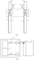
- the mobile terminal specifically includes: a terminal body 10, a camera module 20 detachably connected to the terminal body 10, a first Hall sensor 31, a second Hall sensor 32, and a magnetic structural element 40.
- the terminal body 10 has a placement portion 11 where the camera module 20 can be placed, and the terminal body 10 has a built-in processor 12.
- the first Hall sensor 31 and the second Hall sensor 32 are respectively electrically connected to the processor 12 built in the terminal body 10 and fixedly arranged on a side on which the placement portion 11 of the terminal body 10 is located.
- the magnetic structural element 40 is fixed on an end of the camera module 20 close to the placement portion 11, and when the camera module 20 is placed on the placement portion 11, the magnetic structural element 40 is opposite to the first Hall sensor 31 or the second Hall sensor 32.
- the magnetic structural element 40 may be a magnet.
- the magnetic structural element 40 is disposed on the camera module 20 that is detachable from the terminal body 10, and is opposite to only one of the Hall sensors when the camera module 20 is placed on the placement portion 11, when the camera module 20 is placed on the placement portion 11 of the terminal body 10 in different manners, Hall sensors opposite to the magnetic structural element 40 are different. Therefore, magnetic field strengths of the magnetic structural element detected by the first Hall sensor 31 and the second Hall sensor 32 are different.
- the magnetic field strengths detected by the first Hall sensor 31 and the second Hall sensor 32 can be used to determine the Hall sensor opposite to the magnetic structural element. Since the camera module 20 has a front-facing shooting mode and a rear-facing shooting mode, and the Hall sensors opposite to the magnetic structural element 40 are different in different shooting modes, the processor 12 built in the terminal body 10 can determine the shooting mode of the camera module 20 based on a magnetic field strength signal output by the first Hall sensor 31 and a magnetic field strength signal output by the second Hall sensor 32. That is, in the mobile terminal of the embodiments of the present invention, the shooting mode of the camera module can be determined only by disposing the Hall sensors and the magnetic structural element, the determining logic is simple, and costs are low. Besides, the appearance of the mobile terminal does not need to be additionally modified, and the appearance aesthetics of the mobile terminal can be preserved.
- the terminal body 10 further includes a display screen 13, and the camera module 20 includes a camera 21.
- the orientation of the camera 21 is contrary to the orientation of the display screen 13.
- the orientation of the camera 21 is the same as the orientation of the display screen 13.
- the camera module 20 is placed on the placement portion 11, and when the orientation of the camera 21 is contrary to the orientation of the display screen 13, the magnetic structural element 40 is opposite to the first Hall sensor 31.
- the orientation of the camera 21 is to the same as the orientation of the display screen 13, the magnetic structural element 40 is opposite to the second Hall sensor 32.
- the Hall sensor opposite to the magnetic structural element 40 detects a higher magnetic field strength, while the other Hall sensor detects a lower magnetic field strength.
- the first Hall sensor 31 and the second Hall sensor 32 output corresponding magnetic field strength signals to the processor 12 based on detected magnetic field strengths of the magnetic structural element 40.
- the processor 12 can acquire the first magnetic field strength signal output by the first Hall sensor 31 and the second magnetic field strength signal output by the second Hall sensor 32, and determine the shooting mode of the camera module 20 according to the first magnetic field strength signal and the second magnetic field strength signal.
- FIG. 1 to FIG. 3 are used as an example.
- the first Hall sensor 31 and the second Hall sensor 32 respectively detect that the magnetic field strength E of the magnetic structural element 40 is relatively small.
- the first magnetic field strength signal INT1 output by the first Hall sensor 31 and the second magnetic field strength signal INT2 output by the second Hall sensor 32 are both a first level signal.
- the first Hall sensor 31 detects that the magnetic field strength of the magnetic structural element 40 increases, and when the magnetic field strength E reaches a field strength triggering threshold E0 of the first Hall sensor 31, the first magnetic field strength signal INT1 output by the first Hall sensor 31 is a second level signal.
- the second Hall sensor 32 detects that the magnetic field strength E of the magnetic structural element 40 is small, and the outputted second magnetic field strength signal INT2 is still the first level signal.
- the second Hall sensor 32 detects that the magnetic field strength E of the magnetic structural element 40 increases, and when the magnetic field strength E reaches a field strength triggering threshold E0 of the second Hall sensor 32, the second magnetic field strength signal INT2 output by the second Hall sensor 32 is a second level signal.
- the first Hall sensor 31 detects that the magnetic field strength E of the magnetic structural element 40 is small, and the outputted first magnetic field strength signal INT1 is still the first level signal.
- the first level signal and the second level signal are different level signals, when the first level signal is a high level signal, the second level signal is a low level signal, and when the first level signal is a low level signal, the second level signal is a high level signal.
- the processor 12 can determine the shooting mode of the camera module 20 according to the first magnetic field strength signal output by the first Hall sensor 31 and the second magnetic field strength signal output by the second Hall sensor 32.
- the processor 12 is specifically configured to: in a case that the first magnetic field strength signal is a first level signal and the second magnetic field strength signal is a second level signal, determine that the shooting mode of the camera module 20 is the front-facing shooting mode; and in a case that the first magnetic field strength signal is a second level signal and the second magnetic field strength signal is a first level signal, determine that the shooting mode of the camera module 20 is the rear-facing shooting mode.
- the processor 12 determines the shooting mode of the camera module 20 only based on the first magnetic field strength signal output by the first Hall sensor 31 and the second magnetic field strength signal output by the second Hall sensor 32, the determining logic is simple, and costs are low. Besides, the appearance of the mobile terminal does not need to be additionally modified, and the appearance aesthetics of the mobile terminal can be preserved.
- the processor 12 may also be configured to disable the shooting function of the mobile terminal in a case that the first magnetic field strength signal output by the first Hall sensor 31 and the second magnetic field strength signal output by the second Hall sensor 32 are both the first level signal.
- the magnetic structural element 40 is farther and farther away from the first Hall sensor 31 and the second Hall sensor 32, and the first Hall sensor 31 and the second Hall sensor 32 both detect that the magnetic field strength of the magnetic structural element 40 decreases. Therefore, the first magnetic field strength signal output by the first Hall sensor 31 and the second magnetic field strength signal output by the second Hall sensor 32 are both the first level signal. Based on this, when the processor 12 obtains that the first magnetic field strength signal output by the first Hall sensor 31 and the second magnetic field strength signal output by the second Hall sensor 32 are both the first level signal, the processor 12 can determine that the camera module 20 is detached from the terminal body 10. In this case, by disabling the shooting function of the mobile terminal, power consumption and system resource occupation of the mobile terminal caused by the camera module can be reduced, and the battery life of the mobile terminal can be increased.
- the processor 12 may be further configured to adjust a shooting parameter of the camera module 20 according to the shooting mode.
- the shooting parameter may, for example, include but is not limited to at least one of the following: a shooting speed, a resolution, a focal length, an angle of view, and the like.
- the processor 12 of the mobile terminal adjusts the shooting parameter of the camera module 20 based on the shooting mode of the camera module 20, which can improve the shooting quality and shooting efficiency of the camera module in the corresponding shooting mode.
- the first Hall sensor 31 and the second Hall sensor 32 are symmetrically distributed on two sides relative to the center line of the terminal body 10. Therefore, by separating the first Hall sensor 31 from the second Hall sensor 32, it can be avoided that the difference between the magnetic field strength signals output by the first Hall sensor 31 and the second Hall sensor 32 is small because the first Hall sensor 31 and the second Hall sensor 32 are close to each other. Therefore, based on the first magnetic field strength signal output by the first Hall sensor 31 and the second magnetic field strength signal output by the second Hall sensor 32, it can be effectively and accurately identified whether the shooting mode of the camera module 20 is the front-facing shooting mode or the rear-facing shooting mode.
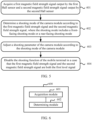
- an embodiment of the present invention provides a shooting mode detection method.
- the method can be applied to the mobile terminal described in the foregoing embodiments of the present invention. Specifically, the method includes:
- Step 401 Acquire a first magnetic field strength signal output by the first Hall sensor and a second magnetic field strength signal output by the second Hall sensor.
- Step 402 Determine a shooting mode of the camera module according to the first magnetic field strength signal and the second magnetic field strength signal, where the shooting mode includes a front-facing shooting mode or a rear-facing shooting mode.
- the magnetic structural element is disposed on the camera module that is detachable from the terminal body, and is opposite to only one of the Hall sensors when the camera module is placed on the placement portion, when the camera module is placed on the placement portion of the terminal body in different manners, Hall sensors opposite to the magnetic structural element are different. Therefore, magnetic field strengths of the magnetic structural element detected by the first Hall sensor and the second Hall sensor are different. Thus, in practical applications, the magnetic field strengths detected by the first Hall sensor and the second Hall sensor can be used to determine the Hall sensor opposite to the magnetic structural element.
- the processor built in the terminal body can determine the shooting mode of the camera module based on magnetic field strength signals output by the first Hall sensor and the second Hall sensor. That is, in the mobile terminal of the embodiments of the present invention, the shooting mode of the camera module can be determined only by disposing the Hall sensors and the magnetic structural element, the determining logic is simple, and costs are low. Besides, the appearance of the mobile terminal does not need to be additionally modified, and the appearance aesthetics of the mobile terminal can be preserved.
- the orientation of the camera in the rear-facing shooting mode, is contrary to the orientation of the display screen.
- the orientation of the camera In the front-facing shooting mode, the orientation of the camera is the same as the orientation of the display screen.
- the camera module is placed on the placement portion, when the orientation of the camera of the camera module is contrary to the orientation of the display screen of the terminal body, the magnetic structural element is opposite to the first Hall sensor, and when the orientation of the camera is the same as the orientation of the display screen, the magnetic structural element is opposite to the second Hall sensor.
- step 402 may include: in a case that the first magnetic field strength signal output by the first Hall sensor is a first level signal and the second magnetic field strength signal output by the second Hall sensor is a second level signal, determining that the shooting mode of the camera module is the front-facing shooting mode.
- the user can hold the camera module to approach the placement portion of the terminal body. If the orientation of the camera is the same as the orientation of the display screen, the magnetic structural element becomes closer to the second Hall sensor in the process in which the camera module approaches the terminal body, the second Hall sensor detects that the magnetic field strength of the magnetic structural element increases, and when the magnetic field strength reaches a field strength triggering threshold of the second Hall sensor, the second magnetic field strength signal INT2 output by the second Hall sensor changes from the first level signal to a second level signal. In this case, the first Hall sensor detects that the magnetic field strength of the magnetic structural element is small, and the outputted first magnetic field strength signal INT1 is still the first level signal.
- the shooting mode of the camera module is the rear-facing shooting mode
- the user can hold the camera module to approach the placement portion of the terminal body. If the orientation of the camera is contrary to the orientation of the display screen, the magnetic structural element becomes closer to the first Hall sensor in the process in which the camera module approaches the terminal body, the first Hall sensor detects that the magnetic field strength of the magnetic structural element increases, and when the magnetic field strength reaches a field strength triggering threshold of the first Hall sensor, the first magnetic field strength signal INT1 output by the first Hall sensor changes from the first level signal to a second level signal. In this case, the second Hall sensor detects that the magnetic field strength of the magnetic structural element is small, and the outputted second magnetic field strength signal INT2 is still the first level signal.
- the first level signal and the second level signal are different level signals, when the first level signal is a high level signal, the second level signal is a low level signal, or when the first level signal is a low level signal, the second level signal is a high level signal.
- the shooting mode of the camera module is determined only based on the first magnetic field strength signal output by the first Hall sensor and the second magnetic field strength signal output by the second Hall sensor, the determining logic is simple, and costs are low. Besides, the appearance of the mobile terminal does not need to be additionally modified, and the appearance aesthetics of the mobile terminal can be preserved.
- the method further includes:
- Step 403 Adjust a shooting parameter of the camera module according to the shooting mode of the camera module.
- the shooting parameter may, for example, include but is not limited to at least one of the following: a shooting speed, a resolution, a focal length, an angle of view, and the like.
- the shooting parameter of the camera module is adjusted based on the shooting mode of the camera module, which can improve the shooting quality and shooting efficiency of the camera module in the corresponding shooting mode.
- the method further includes:
- Step 404 Disable the shooting function of the mobile terminal in a case that the first magnetic field strength signal and the second magnetic field strength signal are both the first level signal.
- the camera module when obtaining that the first magnetic field strength signal output by the first Hall sensor and the second magnetic field strength signal output by the second Hall sensor are both the first level signal, it can be determined that the camera module is detached from the terminal body. In this case, by disabling the shooting function of the mobile terminal, power consumption and system resource occupation of the mobile terminal caused by the camera module can be reduced, and the battery life of the mobile terminal can be increased.
- an embodiment of the present invention further provides a mobile terminal.
- the mobile terminal may include, but is not limited to, any one of a mobile phone, a tablet computer, a smart wearable device, and a personal digital assistant (PDA).
- the mobile terminal 600 includes an acquisition module 601 and a determining module 602.
- the acquisition module 601 is configured to acquire a first magnetic field strength signal output by the first Hall sensor and a second magnetic field strength signal output by the second Hall sensor.
- the determining module 602 is configured to determine a shooting mode of the camera module according to the first magnetic field strength signal and the second magnetic field strength signal, where the shooting mode includes a front-facing shooting mode or a rear-facing shooting mode.
- the mobile terminal provided in the embodiments of the present invention can implement the processes implemented by the mobile terminal in the method embodiments in FIG. 4 and FIG. 5 . To avoid repetition, details are not described herein again.
- the magnetic structural element is disposed on the camera module that is detachable from the terminal body, and is opposite to only one of the Hall sensors when the camera module is placed on the placement portion, when the camera module is placed on the placement portion of the terminal body in different manners, Hall sensors opposite to the magnetic structural element are different. Therefore, magnetic field strengths of the magnetic structural element detected by the first Hall sensor and the second Hall sensor are different. Thus, in practical applications, the magnetic field strengths detected by the first Hall sensor and the second Hall sensor can be used to determine the Hall sensor opposite to the magnetic structural element.
- the processor built in the terminal body can determine the shooting mode of the camera module based on magnetic field strength signals output by the first Hall sensor and the second Hall sensor. That is, in the mobile terminal of the embodiments of the present invention, the shooting mode of the camera module can be determined only by disposing the Hall sensors and the magnetic structural element, the determining logic is simple, and costs are low. Besides, the appearance of the mobile terminal does not need to be additionally modified, and the appearance aesthetics of the mobile terminal can be preserved.
- the camera module is placed on the placement portion, when the orientation of the camera of the camera module is contrary to the orientation of the display screen of the terminal body, the magnetic structural element is opposite to the first Hall sensor, and when the orientation of the camera is the same as the orientation of the display screen, the magnetic structural element is opposite to the second Hall sensor;
- the determining module 602 is specifically configured to:
- the shooting mode of the camera module is determined only based on the first magnetic field strength signal output by the first Hall sensor and the second magnetic field strength signal output by the second Hall sensor, the determining logic is simple, and costs are low. Besides, the appearance of the mobile terminal does not need to be additionally modified, and the appearance aesthetics of the mobile terminal can be preserved.
- the apparatus 600 further includes: an adjustment module, configured to adjust a shooting parameter of the camera module according to the shooting mode of the camera module, where the shooting parameter includes at least one of the following: a shooting speed, a resolution, a focal length, and an angle of view.
- an adjustment module configured to adjust a shooting parameter of the camera module according to the shooting mode of the camera module, where the shooting parameter includes at least one of the following: a shooting speed, a resolution, a focal length, and an angle of view.
- the apparatus 600 further includes: a disabling module, configured to disable the shooting function of the mobile terminal in a case that the first magnetic field strength signal and the second magnetic field strength signal are both the first level signal.
- the camera module when obtaining that the first magnetic field strength signal output by the first Hall sensor and the second magnetic field strength signal output by the second Hall sensor are both the first level signal, it can be determined that the camera module is detached from the terminal body. In this case, by disabling the shooting function of the mobile terminal, power consumption and system resource occupation of the mobile terminal caused by the camera module can be reduced, and the battery life of the mobile terminal can be increased.
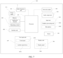
- FIG. 7 is a schematic diagram of a hardware structure of a mobile terminal implementing embodiments of the present invention.
- the mobile terminal 100 includes the terminal body, the camera module detachably connected to the terminal body, the first Hall sensor, the second Hall sensor, and the magnetic structural element according to any one of the above embodiments of the present invention.
- the mobile terminal 100 further includes but is not limited to components such as a radio frequency unit 101, a network module 102, an audio output unit 103, an input unit 104, a sensor 105, a display unit 106, a user input unit 107, an interface unit 108, a memory 109, a processor 110, and a power supply 111. These modules or units can be built in the terminal body.
- the mobile terminal shown in FIG. 7 does not constitute a limitation on the mobile terminal, and the mobile terminal may include more or fewer components than those shown in the figure, or combine some components, or have different component arrangements.
- the mobile terminal includes but is not limited to a mobile phone, a tablet computer, a laptop computer, a palmtop computer, an in-vehicle terminal, a wearable device, a pedometer, and the like.
- the processor 110 is configured to acquire a first magnetic field strength signal output by the first Hall sensor and a second magnetic field strength signal output by the second Hall sensor; and determine a shooting mode of the camera module according to the first magnetic field strength signal and the second magnetic field strength signal, where the shooting mode includes a front-facing shooting mode or a rear-facing shooting mode.
- the magnetic structural element is disposed on the camera module that is detachable from the terminal body, and is opposite to only one of the Hall sensors when the camera module is placed on the placement portion, when the camera module is placed on the placement portion of the terminal body in different manners, Hall sensors opposite to the magnetic structural element are different. Therefore, magnetic field strengths of the magnetic structural element detected by the first Hall sensor and the second Hall sensor are different. Thus, in practical applications, the magnetic field strengths detected by the first Hall sensor and the second Hall sensor can be used to determine the Hall sensor opposite to the magnetic structural element.
- the processor built in the terminal body can determine the shooting mode of the camera module based on magnetic field strength signals output by the first Hall sensor and the second Hall sensor. That is, in the mobile terminal of the embodiments of the present invention, the shooting mode of the camera module can be determined only by disposing the Hall sensors and the magnetic structural element, the determining logic is simple, and costs are low. Besides, the appearance of the mobile terminal does not need to be additionally modified, and the appearance aesthetics of the mobile terminal can be preserved.
- the radio frequency unit 101 may be configured to receive and transmit information, or receive and transmit signals during a call. Specifically, the radio frequency unit 101 receives downlink data from a base station, and transmits the downlink data to the processor 110 for processing; and in addition, transmits uplink data to the base station.
- the radio frequency unit 101 includes, but is not limited to, an antenna, at least one amplifier, a transceiver, a coupler, a low noise amplifier, a duplexer, and the like.
- the radio frequency unit 101 may also communicate with a network and other devices through a wireless communication system.
- the mobile terminal provides wireless broadband Internet access for a user by using a network module 102, for example, helping the user send and receive an email, browsing a web page, and accessing streaming media.
- the audio output unit 103 can convert audio data received by the radio frequency unit 101 or the network module 102 or stored in the memory 109 into an audio signal, and output the audio signal as sound.
- the audio output unit 103 may further provide audio output (for example, call signal receiving sound or message receiving sound) to a specific function performed by the mobile terminal 100.
- the audio output unit 103 includes a speaker, a buzzer, a telephone receiver, and the like.
- the input unit 104 is configured to receive audio or radio frequency signals.
- the input unit 104 may include a graphics processing unit (Graphics Processing Unit, GPU) 1041 and a microphone 1042.
- the graphics processing unit 1041 is configured to process image data of a static picture or a video obtained by an image capture apparatus (for example, a camera) in video capture mode or image capture mode. A processed image frame may be displayed on the display unit 106.
- the image frame processed by the graphics processing unit 1041 may be stored in the memory 109 (or another storage medium) or sent by using the radio frequency unit 101 or the network module 102.
- the microphone 1042 may receive sound and can process the sound into audio data. Processed audio data may be converted, in a call mode, into a format that can be sent to a mobile communication base station by using the radio frequency unit 101 for output.
- the mobile terminal 100 further includes at least one sensor 105, such as an optical sensor, a motion sensor, and another sensor.
- the optical sensor includes an ambient light sensor and a proximity sensor.
- the ambient light sensor may adjust luminance of the display panel 1061 based on brightness of ambient light
- the proximity sensor may disable the display panel 1061 and/or backlight when the mobile terminal 100 approaches an ear.
- an accelerometer sensor may detect magnitude of an acceleration in each direction (generally three axes), and may detect magnitude and a direction of gravity when being static.
- the accelerometer sensor may be used for recognizing a mobile terminal gesture (for example, horizontal and vertical screen switching, a game, or magnetometer posture calibration), a function to vibration recognition (for example, a pedometer or a strike), or the like.
- the sensor 105 may further include a fingerprint sensor, a pressure sensor, an iris sensor, a molecular sensor, a gyroscope, a barometer, a hygrometer, a thermometer, an infrared sensor, and the like. This is not described herein.
- the display unit 106 is configured to display information input by the user or information provided to the user.
- the display unit 106 may include the display panel 1061, and the display panel 1061 may be configured in a form of a liquid crystal display (LCD), an organic light-emitting diode (OLED), or the like.
- LCD liquid crystal display
- OLED organic light-emitting diode
- the user input unit 107 may be configured to receive input digit or character information and generate key signal input to user setting and function control of the mobile terminal.
- the user input unit 107 includes a touch panel 1071 and another input device 1072.
- the touch panel 1071 is also referred to as a touchscreen, and may collect a touch operation of the user on or near the touch panel 1071 (for example, an operation performed on or near the touch panel 1071 by the user by using any appropriate object or accessory such as a finger or a stylus).
- the touch panel 1071 may include two parts: a touch detection apparatus and a touch controller.
- the touch detection apparatus detects a touch location of the user, detects a signal brought by the touch operation, and sends the signal to the touch controller.
- the touch controller receives touch information from the touch detection apparatus, converts the touch information into touch point coordinates, and sends the touch point coordinates to the processor 110, and can receive and execute a command sent by the processor 110.
- the touch panel 1071 may be implemented as a resistive type, a capacitive type, an infrared type, a surface acoustic wave type, or the like.
- the user input unit 107 may further include another input device 1072.
- the another input device 1072 may include but is not limited to: a physical keyboard, a function button (such as a volume control button, a switch button), a trackball, a mouse, and a joystick, which is not described herein.
- the touch panel 1071 may cover the display panel 1061.
- the touch panel 1071 transmits the touch operation to the processor 110 to determine a type of a touch event.
- the processor 110 provides corresponding visual output on the display panel 1061 based on the type of the touch event.
- the touch panel 1071 and the display panel 1061 are used as two independent components to implement input and output functions of the mobile terminal.
- the touch panel 1071 and the display panel 1061 may be integrated to implement the input and output functions of the mobile terminal. This is not specifically limited herein.
- the interface unit 108 is an interface connecting an external apparatus to the mobile terminal 100.
- the external apparatus may include a wired or wireless headset port, an external power supply (or a battery charger) port, a wired or wireless data port, a memory card port, a port for connecting an apparatus having an identification module, an audio input/output (I/O) port, a video I/O port, an earphone port, and the like.
- the interface unit 108 may be configured to receive input (for example, data information and power) from the external apparatus and transmit the received input to one or more elements in the mobile terminal 100, or may be configured to transmit data between the mobile terminal 100 and the external apparatus.
- the memory 109 may be configured to store a software program and various pieces of data.
- the memory 109 may mainly include a program storage area and a data storage area.
- the program storage area may store an operating system, an application required by at least one function (for example, a sound play function or an image display function), and the like.
- the data storage area may store data (for example, audio data or an address book) or the like created based on use of the mobile phone.
- the memory 109 may include a high-speed random access memory or a nonvolatile memory, for example, at least one disk storage device, a flash memory, or other nonvolatile solid-state storage devices.
- the processor 110 is a control center of the mobile terminal, and is connected to all parts of the entire mobile terminal by using various interfaces and lines, and performs various functions of the mobile terminal and processes data by running or executing the software program and/or the module that are stored in the memory 109 and invoking the data stored in the memory 109, to implement overall monitoring on the mobile terminal.
- the processor 110 may include one or more processing units.
- the processor 110 may integrate an application processor and a modem processor.
- the application processor mainly deals with an operating system, a user interface, an application, and the like.
- the modem processor mainly deals with wireless communication. It can be understood that, alternatively, the modem processor may not be integrated into the processor 110.
- the terminal 100 may also include the power supply 111 (for example, a battery) that supplies power to various components.
- the power supply 111 may be logically connected to the processor 110 by using a power supply management system, to implement functions of managing charging, discharging, and power consumption by using the power supply management system.
- the mobile terminal 100 includes some function modules not shown, and details are not described herein.
- An embodiment of the present invention further provides a mobile terminal, including a processor 110, a memory 109, and a computer program stored in the memory 109 and executable on the processor 110.
- the computer program When executed by the processor 110, the computer program implements the foregoing processes of the embodiments of the shooting mode detection method, and a same technical effect can be achieved. To avoid repetition, details are not described herein again.
- Embodiments of the present invention further provide a computer readable storage medium.
- the computer readable storage medium stores a computer program.
- the computer program implements, when executed by a processor, the foregoing processes of the embodiments of the shooting mode detection method, and a same technical effect can be achieved. To avoid repetition, details are not described herein again.
- the computer readable storage medium is, for example, a read-only memory (ROM for short), a random access memory (RAM for short), a magnetic disk, or an optical disc.
- the method in the foregoing embodiments may be implemented by software in addition to a necessary universal hardware platform or by hardware only. In most circumstances, the former is a preferred implementation.
- the technical solutions of the present invention essentially or the part contributing to the related art may be implemented in a form of a software product.
- the computer software product is stored in a storage medium (such as a ROM/RAM, a hard disk, or an optical disc), and includes several instructions for instructing a terminal (which may be mobile phone, a computer, a server, an air conditioner, a network device, or the like) to perform the methods described in the embodiments of the present invention.
Landscapes
- Engineering & Computer Science (AREA)
- Signal Processing (AREA)
- Multimedia (AREA)
- Remote Sensing (AREA)
- Life Sciences & Earth Sciences (AREA)
- Physics & Mathematics (AREA)
- Environmental & Geological Engineering (AREA)
- Electromagnetism (AREA)
- Geology (AREA)
- General Life Sciences & Earth Sciences (AREA)
- General Physics & Mathematics (AREA)
- Geophysics (AREA)
- Human Computer Interaction (AREA)
- Studio Devices (AREA)
- Telephone Function (AREA)
- Structure And Mechanism Of Cameras (AREA)
Claims (9)
- Mobiles Endgerät, das ein Kameramodul (20) aufweist, umfassend:einen Anzeigebildschirm;einen Endgerätekörper (10), wobei der Endgerätekörper einen Platzierungsabschnitt aufweist, wo das Kameramodul (20) platziert werden kann;das Kameramodul (20), lösbar verbunden mit dem Endgerätekörper (10), wobei das Kameramodul (20) eine Kamera umfasst;einen ersten Hall-Sensor (31) und einen zweiten Hall-Sensor (32), wobei der erste Hall-Sensor (31) und der zweite Hall-Sensor (32) jeweils mit einem in den Endgerätekörper (10) eingebauten Prozessor (12) elektrisch verbunden und fest auf einer Seite angeordnet sind, auf der sich der Platzierungsabschnitt des Endgerätekörpers (10) befindet, wobei der erste Hall-Sensor (31) und der zweite Hall-Sensor (32) auf zwei Seiten relativ zur Mittellinie des Endgerätekörpers (10) symmetrisch verteilt sind; undein magnetisches Strukturelement (40), wobei das magnetische Strukturelement (40) an einem Ende des Kameramoduls (20) nahe dem Platzierungsabschnitt befestigt ist und das Kameramodul (20) an dem Platzierungsabschnitt platziert ist,wobei das Kameramodul (20) einen nach vorn gewandten Aufnahmemodus und einen nach hinten gewandten Aufnahmemodus aufweist, wobei in dem nach vorn gewandten Aufnahmemodus die Ausrichtung der Kamera die gleiche wie die Ausrichtung des Anzeigebildschirms ist und sich das magnetische Strukturelement gegenüber dem zweiten Hall-Sensor (32) befindet; und in dem nach hinten gewandten Aufnahmemodus die Ausrichtung der Kamera entgegengesetzt zur Ausrichtung des Anzeigebildschirms ist und sich das magnetische Strukturelement gegenüber dem ersten Hall-Sensor (31) befindet;wobei der Prozessor (12) dazu ausgestaltet ist:einen ersten Magnetfeldstärken-Signalausgang durch den ersten Hall-Sensor (31) und einen zweiten Magnetfeldstärken-Signalausgang durch den zweiten Hall-Sensor (32) zu erfassen; undeinen Aufnahmemodus des Kameramoduls (20) gemäß dem ersten Magnetfeldstärkensignal und dem zweiten Magnetfeldstärkensignal festzustellen.
- Mobiles Endgerät nach Anspruch 1, wobei der Prozessor (12) ferner dazu ausgelegt ist:in einem Fall, in dem das erste Magnetfeldstärkensignal ein Signal von einem ersten Pegel ist und das zweite Magnetfeldstärkensignal ein Signal von einem zweiten Pegel ist, festzustellen, dass der Aufnahmemodus des Kameramoduls (20) der nach vorn gewandte Aufnahmemodus ist; undin einem Fall, in dem das erste Magnetfeldstärkensignal ein Signal von einem zweiten Pegel ist und das zweite Magnetfeldstärkensignal ein Signal von einem ersten Pegel ist, festzustellen, dass der Aufnahmemodus des Kameramoduls (20) der nach hinten gewandte Aufnahmemodus ist,wobei dann, wenn das Signal von einem ersten Pegel ein Hochpegelsignal ist, das Signal von einem zweiten Pegel ein Tiefpegelsignal ist, oder wenn das Signal von einem ersten Pegel ein Tiefpegelsignal ist, das Signal von einem zweiten Pegel ein Hochpegelsignal ist.
- Mobiles Endgerät nach Anspruch 2, wobei
der Prozessor (12) ferner dazu ausgestaltet ist, die Aufnahmefunktion des mobilen Endgeräts in einem Fall, in dem das erste Magnetfeldstärkensignal und das zweite Magnetfeldstärkensignal beide das Signal von einem ersten Pegel sind, zu deaktivieren. - Mobiles Endgerät nach Anspruch 1, wobei
der Prozessor (12) ferner dazu ausgestaltet ist, einen Aufnahmeparameter des Kameramoduls (20) gemäß dem Aufnahmemodus anzupassen, wobei der Aufnahmeparameter mindestens eines von den Folgenden umfasst: eine Aufnahmegeschwindigkeit, eine Auflösung, eine Brennweite und einen Blickwinkel. - Verfahren zum Detektieren eines Aufnahmemodus, ausgeführt von dem mobilen Endgerät nach einem der Ansprüche 1 bis 4, dadurch gekennzeichnet, dass es Folgendes umfasst:Erfassen (401) eines ersten Magnetfeldstärken-Signalausgangs durch den ersten Hall-Sensor (31) und eines zweiten Magnetfeldstärken-Signalausgangs durch den zweiten Hall-Sensor (32); undFeststellen (402) eines Aufnahmemodus des Kameramoduls (20) gemäß dem ersten Magnetfeldstärkensignal und dem zweiten Magnetfeldstärkensignal, wobei der Aufnahmemodus einen nach vorn gewandten Aufnahmemodus oder einen nach hinten gewandten Aufnahmemodus umfasst.
- Verfahren nach Anspruch 5, wobei das Kameramodul (20) auf dem Platzierungsabschnitt platziert ist, wobei dann, wenn die Ausrichtung der Kamera des Kameramoduls (20) entgegengesetzt zur Ausrichtung des Anzeigebildschirms des Endgerätekörpers (10) ist, das magnetische Strukturelement (40) entgegengesetzt zum ersten Hall-Sensor (31) ist, und dann, wenn die Ausrichtung der Kamera die gleiche wie die Ausrichtung des Anzeigebildschirms ist, das magnetische Strukturelement entgegengesetzt zum zweiten Hall-Sensor (32) ist; und
das Feststellen (402) eines Aufnahmemodus des Kameramoduls (20) gemäß dem ersten Magnetfeldstärkensignal und dem zweiten Magnetfeldstärkensignal Folgendes umfasst:in einem Fall, in dem das erste Magnetfeldstärkensignal ein Signal von einem ersten Pegel ist und das zweite Magnetfeldstärkensignal ein Signal von einem zweiten Pegel ist, das Feststellen, dass der Aufnahmemodus des Kameramoduls (20) der nach vorn gewandte Aufnahmemodus ist; undin einem Fall, in dem das erste Magnetfeldstärkensignal ein Signal von einem zweiten Pegel ist und das zweite Magnetfeldstärkensignal ein Signal von einem ersten Pegel ist, das Feststellen, dass der Aufnahmemodus des Kameramoduls (20) der nach hinten gewandte Aufnahmemodus ist;wobei dann, wenn das Signal von einem ersten Pegel ein Hochpegelsignal ist, das Signal von einem zweiten Pegel ein Tiefpegelsignal ist, oder wenn das Signal von einem ersten Pegel ein Tiefpegelsignal ist, das Signal von einem zweiten Pegel ein Hochpegelsignal ist. - Verfahren nach Anspruch 6, wobei das Verfahren ferner umfasst:
Deaktivieren (404) der Aufnahmefunktion des mobilen Endgeräts in einem Fall, in dem das erste Magnetfeldstärkensignal und das zweite Magnetfeldstärkensignal beide das Signal von einem ersten Pegel sind. - Verfahren gemäß Anspruch 5, wobei das Verfahren ferner umfasst:Einstellen (403) eines Aufnahmeparameters des Kameramoduls (20) gemäß dem Aufnahmemodus des Kameramoduls (20) ;wobei der Aufnahmeparameter mindestens eines von den Folgenden umfasst: eine Aufnahmegeschwindigkeit, eine Auflösung, eine Brennweite und einen Blickwinkel.
- Computerlesbares Speichermedium, das ein Computerprogramm speichert, dadurch gekennzeichnet, dass das Computerprogramm, wenn es von einem Prozessor ausgeführt wird, den Prozessor veranlasst, die Schritte des Verfahrens nach einem der Ansprüche 5 bis 8 auszuführen.
Applications Claiming Priority (2)
| Application Number | Priority Date | Filing Date | Title |
|---|---|---|---|
| CN202010073817.7A CN111246061B (zh) | 2020-01-22 | 2020-01-22 | 移动终端、拍摄模式的检测方法及存储介质 |
| PCT/CN2021/072902 WO2021147911A1 (zh) | 2020-01-22 | 2021-01-20 | 移动终端、拍摄模式的检测方法及存储介质 |
Publications (3)
| Publication Number | Publication Date |
|---|---|
| EP4096207A1 EP4096207A1 (de) | 2022-11-30 |
| EP4096207A4 EP4096207A4 (de) | 2023-08-09 |
| EP4096207B1 true EP4096207B1 (de) | 2025-01-08 |
Family
ID=70876363
Family Applications (1)
| Application Number | Title | Priority Date | Filing Date |
|---|---|---|---|
| EP21744020.5A Active EP4096207B1 (de) | 2020-01-22 | 2021-01-20 | Mobiles endgerät, verfahren zum detektieren des bildaufnahmemodus und speichermedium |
Country Status (5)
| Country | Link |
|---|---|
| US (1) | US12279040B2 (de) |
| EP (1) | EP4096207B1 (de) |
| CN (1) | CN111246061B (de) |
| ES (1) | ES3014533T3 (de) |
| WO (1) | WO2021147911A1 (de) |
Families Citing this family (3)
| Publication number | Priority date | Publication date | Assignee | Title |
|---|---|---|---|---|
| CN111246061B (zh) * | 2020-01-22 | 2021-08-06 | 维沃移动通信有限公司 | 移动终端、拍摄模式的检测方法及存储介质 |
| CN114026879A (zh) * | 2020-10-20 | 2022-02-08 | 深圳市大疆创新科技有限公司 | 传声组件、传声器、防风件、传声设备以及传声方法 |
| CN113994653A (zh) * | 2020-10-20 | 2022-01-28 | 深圳市大疆创新科技有限公司 | 摄像组件、相机、滤镜模组、云台相机以及拍摄方法 |
Family Cites Families (21)
| Publication number | Priority date | Publication date | Assignee | Title |
|---|---|---|---|---|
| JP2006295838A (ja) * | 2005-04-14 | 2006-10-26 | Fuji Photo Film Co Ltd | カメラシステム |
| CN103475782B (zh) * | 2013-09-13 | 2015-09-30 | 广东欧珀移动通信有限公司 | 提供快捷控制功能的方法及移动终端 |
| CN104023105A (zh) * | 2014-06-13 | 2014-09-03 | 广东欧珀移动通信有限公司 | 一种移动终端摄像头角度旋转检测装置及其检测方法 |
| CN104320508A (zh) * | 2014-10-27 | 2015-01-28 | 广东欧珀移动通信有限公司 | 一种具有旋转摄像头的移动终端及其摄像头角度控制方法 |
| CN104320591B (zh) * | 2014-11-21 | 2018-07-03 | 广东欧珀移动通信有限公司 | 一种控制摄像头前后切换的方法、装置和一种智能终端 |
| KR20160085553A (ko) * | 2015-01-08 | 2016-07-18 | 엘지전자 주식회사 | 회전 접속부 및 이를 구비한 이동 단말기 |
| CN104618634B (zh) * | 2015-02-12 | 2017-08-29 | 广东欧珀移动通信有限公司 | 移动终端及校准摄像头旋转角度的方法 |
| CN104601895B (zh) * | 2015-02-12 | 2017-10-17 | 广东欧珀移动通信有限公司 | 应用于移动终端的跳闪控制方法及移动终端 |
| CN106453694B (zh) * | 2015-08-10 | 2019-06-21 | 华为终端有限公司 | 终端设备 |
| CN107948363A (zh) * | 2016-11-16 | 2018-04-20 | 广东欧珀移动通信有限公司 | 一种移动终端的摄像头安装结构及移动终端 |
| WO2018194557A1 (en) * | 2017-04-18 | 2018-10-25 | Hewlett-Packard Development Company, L.P. | Digital pens with cameras for videoconferencing |
| KR20190021550A (ko) * | 2017-08-23 | 2019-03-06 | 주식회사 하미코리아 | 나노 흡착패드를 이용한 이동단말기용 자석 거치대 |
| CN107613185B (zh) * | 2017-11-07 | 2021-01-26 | 广东天波信息技术股份有限公司 | 一种摄像头360°翻转装置 |
| CN107819907B (zh) * | 2017-11-14 | 2019-12-27 | 维沃移动通信有限公司 | 一种摄像头控制方法及移动终端 |
| CN108924282A (zh) * | 2018-06-08 | 2018-11-30 | Oppo广东移动通信有限公司 | 电子装置和跌落保护控制方法 |
| CN110620830A (zh) * | 2018-06-19 | 2019-12-27 | Oppo广东移动通信有限公司 | 电子装置和跌落保护控制方法 |
| CN109873949A (zh) * | 2019-01-31 | 2019-06-11 | 维沃移动通信有限公司 | 一种摄像头控制系统、摄像头控制方法及移动终端 |
| CN109951702B (zh) * | 2019-03-29 | 2024-04-05 | 荣耀终端有限公司 | 位置检测机构、移动终端及位置检测方法 |
| CN110581938B (zh) * | 2019-08-06 | 2024-05-03 | 深圳传音控股股份有限公司 | 移动终端及移动终端控制方法、计算机存储介质 |
| CN110581952A (zh) * | 2019-09-17 | 2019-12-17 | 深圳市万普拉斯科技有限公司 | 摄像头升降控制方法、装置和移动终端 |
| CN111246061B (zh) * | 2020-01-22 | 2021-08-06 | 维沃移动通信有限公司 | 移动终端、拍摄模式的检测方法及存储介质 |
-
2020
- 2020-01-22 CN CN202010073817.7A patent/CN111246061B/zh active Active
-
2021
- 2021-01-20 WO PCT/CN2021/072902 patent/WO2021147911A1/zh not_active Ceased
- 2021-01-20 ES ES21744020T patent/ES3014533T3/es active Active
- 2021-01-20 EP EP21744020.5A patent/EP4096207B1/de active Active
-
2022
- 2022-07-21 US US17/870,779 patent/US12279040B2/en active Active
Also Published As
| Publication number | Publication date |
|---|---|
| EP4096207A4 (de) | 2023-08-09 |
| ES3014533T3 (en) | 2025-04-23 |
| US12279040B2 (en) | 2025-04-15 |
| EP4096207A1 (de) | 2022-11-30 |
| WO2021147911A1 (zh) | 2021-07-29 |
| CN111246061B (zh) | 2021-08-06 |
| CN111246061A (zh) | 2020-06-05 |
| US20220360709A1 (en) | 2022-11-10 |
Similar Documents
| Publication | Publication Date | Title |
|---|---|---|
| EP3779738A1 (de) | Verfahren zur fingerabdruckidentifikation und mobiles endgerät | |
| CN109067418B (zh) | 一种天线控制方法及移动终端 | |
| CN108494030B (zh) | 一种无线充电方法、终端及发射端设备 | |
| US12238408B2 (en) | Display method performed by electronic device and electronic device | |
| US12279040B2 (en) | Mobile terminal having detachably connected camera module, hall sensor, and magnet, shooting mode detection method, and storage medium | |
| CN111049510B (zh) | 触控按键、控制方法及电子设备 | |
| CN110300267B (zh) | 拍照方法和终端设备 | |
| CN109739394B (zh) | 一种sar值的处理方法、移动终端 | |
| CN107895143A (zh) | 一种指纹信息处理方法、移动终端及计算机可读存储介质 | |
| CN108846663A (zh) | 一种二维码调整方法、装置及移动终端 | |
| CN110365853A (zh) | 一种提示方法及电子设备 | |
| CN111443815A (zh) | 一种振动提醒方法及电子设备 | |
| CN110457885A (zh) | 一种操作方法及电子设备 | |
| CN110442261B (zh) | 电子设备及其触控操作检测方法 | |
| CN108600557A (zh) | 一种屏幕亮灭控制方法和移动终端 | |
| CN109257489B (zh) | 一种显示方法及移动终端 | |
| CN108924319B (zh) | 一种接近检测方法和移动终端 | |
| CN107885566A (zh) | 显示控制方法、移动终端及计算机可读存储介质 | |
| CN111399792B (zh) | 一种内容共享方法及电子设备 | |
| CN110636225B (zh) | 拍照方法及电子设备 | |
| CN108225278A (zh) | 一种测距方法、移动终端 | |
| CN111356221A (zh) | 一种发射功率的调整方法及电子设备 | |
| CN107967202B (zh) | 一种折叠屏开合状态确定方法、移动终端 | |
| CN111328132B (zh) | 一种发射功率的调整方法及电子设备 | |
| CN108681429A (zh) | 一种亮屏控制方法及移动终端 |
Legal Events
| Date | Code | Title | Description |
|---|---|---|---|
| STAA | Information on the status of an ep patent application or granted ep patent |
Free format text: STATUS: THE INTERNATIONAL PUBLICATION HAS BEEN MADE |
|
| PUAI | Public reference made under article 153(3) epc to a published international application that has entered the european phase |
Free format text: ORIGINAL CODE: 0009012 |
|
| STAA | Information on the status of an ep patent application or granted ep patent |
Free format text: STATUS: REQUEST FOR EXAMINATION WAS MADE |
|
| 17P | Request for examination filed |
Effective date: 20220808 |
|
| AK | Designated contracting states |
Kind code of ref document: A1 Designated state(s): AL AT BE BG CH CY CZ DE DK EE ES FI FR GB GR HR HU IE IS IT LI LT LU LV MC MK MT NL NO PL PT RO RS SE SI SK SM TR |
|
| DAV | Request for validation of the european patent (deleted) | ||
| DAX | Request for extension of the european patent (deleted) | ||
| REG | Reference to a national code |
Ref country code: DE Ref legal event code: R079 Free format text: PREVIOUS MAIN CLASS: H04N0005225000 Ipc: H04N0023667000 Ref country code: DE Ref legal event code: R079 Ref document number: 602021024692 Country of ref document: DE Free format text: PREVIOUS MAIN CLASS: H04N0005225000 Ipc: H04N0023667000 |
|
| A4 | Supplementary search report drawn up and despatched |
Effective date: 20230707 |
|
| RIC1 | Information provided on ipc code assigned before grant |
Ipc: G01V 3/08 20060101ALI20230703BHEP Ipc: H04N 23/663 20230101ALI20230703BHEP Ipc: H04N 23/57 20230101ALI20230703BHEP Ipc: H04M 1/02 20060101ALI20230703BHEP Ipc: H04N 23/667 20230101AFI20230703BHEP |
|
| GRAP | Despatch of communication of intention to grant a patent |
Free format text: ORIGINAL CODE: EPIDOSNIGR1 |
|
| STAA | Information on the status of an ep patent application or granted ep patent |
Free format text: STATUS: GRANT OF PATENT IS INTENDED |
|
| RIC1 | Information provided on ipc code assigned before grant |
Ipc: G01V 3/08 20060101ALI20241004BHEP Ipc: H04N 23/663 20230101ALI20241004BHEP Ipc: H04N 23/57 20230101ALI20241004BHEP Ipc: H04M 1/02 20060101ALI20241004BHEP Ipc: H04N 23/667 20230101AFI20241004BHEP |
|
| GRAS | Grant fee paid |
Free format text: ORIGINAL CODE: EPIDOSNIGR3 |
|
| INTG | Intention to grant announced |
Effective date: 20241031 |
|
| GRAA | (expected) grant |
Free format text: ORIGINAL CODE: 0009210 |
|
| STAA | Information on the status of an ep patent application or granted ep patent |
Free format text: STATUS: THE PATENT HAS BEEN GRANTED |
|
| AK | Designated contracting states |
Kind code of ref document: B1 Designated state(s): AL AT BE BG CH CY CZ DE DK EE ES FI FR GB GR HR HU IE IS IT LI LT LU LV MC MK MT NL NO PL PT RO RS SE SI SK SM TR |
|
| REG | Reference to a national code |
Ref country code: GB Ref legal event code: FG4D |
|
| REG | Reference to a national code |
Ref country code: CH Ref legal event code: EP |
|
| REG | Reference to a national code |
Ref country code: DE Ref legal event code: R096 Ref document number: 602021024692 Country of ref document: DE |
|
| REG | Reference to a national code |
Ref country code: IE Ref legal event code: FG4D |
|
| REG | Reference to a national code |
Ref country code: NL Ref legal event code: FP |
|
| REG | Reference to a national code |
Ref country code: ES Ref legal event code: FG2A Ref document number: 3014533 Country of ref document: ES Kind code of ref document: T3 Effective date: 20250423 |
|
| PGFP | Annual fee paid to national office [announced via postgrant information from national office to epo] |
Ref country code: AT Payment date: 20250417 Year of fee payment: 5 |
|
| REG | Reference to a national code |
Ref country code: LT Ref legal event code: MG9D |
|
| REG | Reference to a national code |
Ref country code: AT Ref legal event code: MK05 Ref document number: 1759092 Country of ref document: AT Kind code of ref document: T Effective date: 20250108 |
|
| PG25 | Lapsed in a contracting state [announced via postgrant information from national office to epo] |
Ref country code: RS Free format text: LAPSE BECAUSE OF FAILURE TO SUBMIT A TRANSLATION OF THE DESCRIPTION OR TO PAY THE FEE WITHIN THE PRESCRIBED TIME-LIMIT Effective date: 20250408 |
|
| PG25 | Lapsed in a contracting state [announced via postgrant information from national office to epo] |
Ref country code: FI Free format text: LAPSE BECAUSE OF FAILURE TO SUBMIT A TRANSLATION OF THE DESCRIPTION OR TO PAY THE FEE WITHIN THE PRESCRIBED TIME-LIMIT Effective date: 20250108 |
|
| PG25 | Lapsed in a contracting state [announced via postgrant information from national office to epo] |
Ref country code: PL Free format text: LAPSE BECAUSE OF FAILURE TO SUBMIT A TRANSLATION OF THE DESCRIPTION OR TO PAY THE FEE WITHIN THE PRESCRIBED TIME-LIMIT Effective date: 20250108 |
|
| PG25 | Lapsed in a contracting state [announced via postgrant information from national office to epo] |
Ref country code: IS Free format text: LAPSE BECAUSE OF FAILURE TO SUBMIT A TRANSLATION OF THE DESCRIPTION OR TO PAY THE FEE WITHIN THE PRESCRIBED TIME-LIMIT Effective date: 20250508 Ref country code: NO Free format text: LAPSE BECAUSE OF FAILURE TO SUBMIT A TRANSLATION OF THE DESCRIPTION OR TO PAY THE FEE WITHIN THE PRESCRIBED TIME-LIMIT Effective date: 20250408 |
|
| PG25 | Lapsed in a contracting state [announced via postgrant information from national office to epo] |
Ref country code: HR Free format text: LAPSE BECAUSE OF FAILURE TO SUBMIT A TRANSLATION OF THE DESCRIPTION OR TO PAY THE FEE WITHIN THE PRESCRIBED TIME-LIMIT Effective date: 20250108 |
|
| PG25 | Lapsed in a contracting state [announced via postgrant information from national office to epo] |
Ref country code: PT Free format text: LAPSE BECAUSE OF FAILURE TO SUBMIT A TRANSLATION OF THE DESCRIPTION OR TO PAY THE FEE WITHIN THE PRESCRIBED TIME-LIMIT Effective date: 20250508 Ref country code: LV Free format text: LAPSE BECAUSE OF FAILURE TO SUBMIT A TRANSLATION OF THE DESCRIPTION OR TO PAY THE FEE WITHIN THE PRESCRIBED TIME-LIMIT Effective date: 20250108 |
|
| PG25 | Lapsed in a contracting state [announced via postgrant information from national office to epo] |
Ref country code: BG Free format text: LAPSE BECAUSE OF FAILURE TO SUBMIT A TRANSLATION OF THE DESCRIPTION OR TO PAY THE FEE WITHIN THE PRESCRIBED TIME-LIMIT Effective date: 20250108 Ref country code: GR Free format text: LAPSE BECAUSE OF FAILURE TO SUBMIT A TRANSLATION OF THE DESCRIPTION OR TO PAY THE FEE WITHIN THE PRESCRIBED TIME-LIMIT Effective date: 20250409 |
|
| PG25 | Lapsed in a contracting state [announced via postgrant information from national office to epo] |
Ref country code: AT Free format text: LAPSE BECAUSE OF FAILURE TO SUBMIT A TRANSLATION OF THE DESCRIPTION OR TO PAY THE FEE WITHIN THE PRESCRIBED TIME-LIMIT Effective date: 20250108 |
|
| REG | Reference to a national code |
Ref country code: CH Ref legal event code: PL |
|
| PG25 | Lapsed in a contracting state [announced via postgrant information from national office to epo] |
Ref country code: SE Free format text: LAPSE BECAUSE OF FAILURE TO SUBMIT A TRANSLATION OF THE DESCRIPTION OR TO PAY THE FEE WITHIN THE PRESCRIBED TIME-LIMIT Effective date: 20250108 |
|
| PG25 | Lapsed in a contracting state [announced via postgrant information from national office to epo] |
Ref country code: LU Free format text: LAPSE BECAUSE OF NON-PAYMENT OF DUE FEES Effective date: 20250120 |
|
| PG25 | Lapsed in a contracting state [announced via postgrant information from national office to epo] |
Ref country code: SM Free format text: LAPSE BECAUSE OF FAILURE TO SUBMIT A TRANSLATION OF THE DESCRIPTION OR TO PAY THE FEE WITHIN THE PRESCRIBED TIME-LIMIT Effective date: 20250108 |
|
| REG | Reference to a national code |
Ref country code: DE Ref legal event code: R097 Ref document number: 602021024692 Country of ref document: DE |
|
| PG25 | Lapsed in a contracting state [announced via postgrant information from national office to epo] |
Ref country code: DK Free format text: LAPSE BECAUSE OF FAILURE TO SUBMIT A TRANSLATION OF THE DESCRIPTION OR TO PAY THE FEE WITHIN THE PRESCRIBED TIME-LIMIT Effective date: 20250108 |
|
| PG25 | Lapsed in a contracting state [announced via postgrant information from national office to epo] |
Ref country code: MC Free format text: LAPSE BECAUSE OF FAILURE TO SUBMIT A TRANSLATION OF THE DESCRIPTION OR TO PAY THE FEE WITHIN THE PRESCRIBED TIME-LIMIT Effective date: 20250108 |
|
| PG25 | Lapsed in a contracting state [announced via postgrant information from national office to epo] |
Ref country code: BE Free format text: LAPSE BECAUSE OF NON-PAYMENT OF DUE FEES Effective date: 20250131 |
|
| PG25 | Lapsed in a contracting state [announced via postgrant information from national office to epo] |
Ref country code: CH Free format text: LAPSE BECAUSE OF NON-PAYMENT OF DUE FEES Effective date: 20250131 |
|
| PG25 | Lapsed in a contracting state [announced via postgrant information from national office to epo] |
Ref country code: EE Free format text: LAPSE BECAUSE OF FAILURE TO SUBMIT A TRANSLATION OF THE DESCRIPTION OR TO PAY THE FEE WITHIN THE PRESCRIBED TIME-LIMIT Effective date: 20250108 Ref country code: CZ Free format text: LAPSE BECAUSE OF FAILURE TO SUBMIT A TRANSLATION OF THE DESCRIPTION OR TO PAY THE FEE WITHIN THE PRESCRIBED TIME-LIMIT Effective date: 20250108 |
|
| REG | Reference to a national code |
Ref country code: BE Ref legal event code: MM Effective date: 20250131 |
|
| PG25 | Lapsed in a contracting state [announced via postgrant information from national office to epo] |
Ref country code: RO Free format text: LAPSE BECAUSE OF FAILURE TO SUBMIT A TRANSLATION OF THE DESCRIPTION OR TO PAY THE FEE WITHIN THE PRESCRIBED TIME-LIMIT Effective date: 20250108 |
|
| PG25 | Lapsed in a contracting state [announced via postgrant information from national office to epo] |
Ref country code: SK Free format text: LAPSE BECAUSE OF FAILURE TO SUBMIT A TRANSLATION OF THE DESCRIPTION OR TO PAY THE FEE WITHIN THE PRESCRIBED TIME-LIMIT Effective date: 20250108 |
|
| PLBE | No opposition filed within time limit |
Free format text: ORIGINAL CODE: 0009261 |
|
| STAA | Information on the status of an ep patent application or granted ep patent |
Free format text: STATUS: NO OPPOSITION FILED WITHIN TIME LIMIT |
|
| 26N | No opposition filed |
Effective date: 20251009 |
|
| PGFP | Annual fee paid to national office [announced via postgrant information from national office to epo] |
Ref country code: GB Payment date: 20251127 Year of fee payment: 6 |
|
| PG25 | Lapsed in a contracting state [announced via postgrant information from national office to epo] |
Ref country code: IT Free format text: LAPSE BECAUSE OF NON-PAYMENT OF DUE FEES Effective date: 20250120 |
|
| PGFP | Annual fee paid to national office [announced via postgrant information from national office to epo] |
Ref country code: NL Payment date: 20251215 Year of fee payment: 6 Ref country code: FR Payment date: 20251128 Year of fee payment: 6 |
|
| PG25 | Lapsed in a contracting state [announced via postgrant information from national office to epo] |
Ref country code: IE Free format text: LAPSE BECAUSE OF NON-PAYMENT OF DUE FEES Effective date: 20250120 |
|
| PGFP | Annual fee paid to national office [announced via postgrant information from national office to epo] |
Ref country code: ES Payment date: 20260213 Year of fee payment: 6 |
|
| PGFP | Annual fee paid to national office [announced via postgrant information from national office to epo] |
Ref country code: DE Payment date: 20251203 Year of fee payment: 6 |