EP4095510A1 - Welding defect inspection method - Google Patents
Welding defect inspection method Download PDFInfo
- Publication number
- EP4095510A1 EP4095510A1 EP21858448.0A EP21858448A EP4095510A1 EP 4095510 A1 EP4095510 A1 EP 4095510A1 EP 21858448 A EP21858448 A EP 21858448A EP 4095510 A1 EP4095510 A1 EP 4095510A1
- Authority
- EP
- European Patent Office
- Prior art keywords
- strength
- welding
- electrode
- welding defect
- tensile strength
- Prior art date
- Legal status (The legal status is an assumption and is not a legal conclusion. Google has not performed a legal analysis and makes no representation as to the accuracy of the status listed.)
- Pending
Links
- 238000003466 welding Methods 0.000 title claims abstract description 186
- 230000007547 defect Effects 0.000 title claims abstract description 114
- 238000000034 method Methods 0.000 title claims abstract description 98
- 238000007689 inspection Methods 0.000 title description 19
- 238000004519 manufacturing process Methods 0.000 claims abstract description 14
- 230000000712 assembly Effects 0.000 claims description 3
- 238000000429 assembly Methods 0.000 claims description 3
- OKTJSMMVPCPJKN-UHFFFAOYSA-N Carbon Chemical compound [C] OKTJSMMVPCPJKN-UHFFFAOYSA-N 0.000 description 13
- PXHVJJICTQNCMI-UHFFFAOYSA-N Nickel Chemical compound [Ni] PXHVJJICTQNCMI-UHFFFAOYSA-N 0.000 description 10
- 238000005259 measurement Methods 0.000 description 10
- 229910052782 aluminium Inorganic materials 0.000 description 9
- 230000008569 process Effects 0.000 description 9
- 229910052799 carbon Inorganic materials 0.000 description 7
- -1 aluminum-cadmium Chemical compound 0.000 description 6
- 238000010586 diagram Methods 0.000 description 6
- 239000011267 electrode slurry Substances 0.000 description 6
- 239000007774 positive electrode material Substances 0.000 description 6
- 239000004020 conductor Substances 0.000 description 5
- 229910052759 nickel Inorganic materials 0.000 description 5
- 238000003825 pressing Methods 0.000 description 5
- 239000010936 titanium Substances 0.000 description 5
- 229910052719 titanium Inorganic materials 0.000 description 5
- RTAQQCXQSZGOHL-UHFFFAOYSA-N Titanium Chemical compound [Ti] RTAQQCXQSZGOHL-UHFFFAOYSA-N 0.000 description 4
- 239000011149 active material Substances 0.000 description 4
- XAGFODPZIPBFFR-UHFFFAOYSA-N aluminium Chemical compound [Al] XAGFODPZIPBFFR-UHFFFAOYSA-N 0.000 description 4
- 239000011230 binding agent Substances 0.000 description 4
- 239000010408 film Substances 0.000 description 4
- 239000007773 negative electrode material Substances 0.000 description 4
- 229920000642 polymer Polymers 0.000 description 4
- 229910001220 stainless steel Inorganic materials 0.000 description 4
- 239000010935 stainless steel Substances 0.000 description 4
- 229910052723 transition metal Inorganic materials 0.000 description 4
- 150000003624 transition metals Chemical class 0.000 description 4
- HBBGRARXTFLTSG-UHFFFAOYSA-N Lithium ion Chemical compound [Li+] HBBGRARXTFLTSG-UHFFFAOYSA-N 0.000 description 3
- 230000008859 change Effects 0.000 description 3
- 229910052802 copper Inorganic materials 0.000 description 3
- 239000010949 copper Substances 0.000 description 3
- 239000007772 electrode material Substances 0.000 description 3
- 229910052731 fluorine Inorganic materials 0.000 description 3
- 229910052742 iron Inorganic materials 0.000 description 3
- 229910001416 lithium ion Inorganic materials 0.000 description 3
- 229910052749 magnesium Inorganic materials 0.000 description 3
- 229910052748 manganese Inorganic materials 0.000 description 3
- 239000011572 manganese Substances 0.000 description 3
- 239000000463 material Substances 0.000 description 3
- 229910052751 metal Inorganic materials 0.000 description 3
- 239000002184 metal Substances 0.000 description 3
- 239000000203 mixture Substances 0.000 description 3
- 239000004745 nonwoven fabric Substances 0.000 description 3
- 239000000126 substance Substances 0.000 description 3
- RYGMFSIKBFXOCR-UHFFFAOYSA-N Copper Chemical compound [Cu] RYGMFSIKBFXOCR-UHFFFAOYSA-N 0.000 description 2
- 229920002943 EPDM rubber Polymers 0.000 description 2
- 239000004698 Polyethylene Substances 0.000 description 2
- 239000004743 Polypropylene Substances 0.000 description 2
- BQCADISMDOOEFD-UHFFFAOYSA-N Silver Chemical compound [Ag] BQCADISMDOOEFD-UHFFFAOYSA-N 0.000 description 2
- XLOMVQKBTHCTTD-UHFFFAOYSA-N Zinc monoxide Chemical compound [Zn]=O XLOMVQKBTHCTTD-UHFFFAOYSA-N 0.000 description 2
- 230000008901 benefit Effects 0.000 description 2
- WMWLMWRWZQELOS-UHFFFAOYSA-N bismuth(iii) oxide Chemical compound O=[Bi]O[Bi]=O WMWLMWRWZQELOS-UHFFFAOYSA-N 0.000 description 2
- 229910052796 boron Inorganic materials 0.000 description 2
- 229910052804 chromium Inorganic materials 0.000 description 2
- 238000007599 discharging Methods 0.000 description 2
- 238000001035 drying Methods 0.000 description 2
- 229920001971 elastomer Polymers 0.000 description 2
- 239000003792 electrolyte Substances 0.000 description 2
- 239000000835 fiber Substances 0.000 description 2
- 239000006260 foam Substances 0.000 description 2
- 239000011888 foil Substances 0.000 description 2
- YBMRDBCBODYGJE-UHFFFAOYSA-N germanium dioxide Chemical compound O=[Ge]=O YBMRDBCBODYGJE-UHFFFAOYSA-N 0.000 description 2
- 229910002804 graphite Inorganic materials 0.000 description 2
- 239000010439 graphite Substances 0.000 description 2
- 229910052744 lithium Inorganic materials 0.000 description 2
- 229910000625 lithium cobalt oxide Inorganic materials 0.000 description 2
- BFZPBUKRYWOWDV-UHFFFAOYSA-N lithium;oxido(oxo)cobalt Chemical compound [Li+].[O-][Co]=O BFZPBUKRYWOWDV-UHFFFAOYSA-N 0.000 description 2
- 229910044991 metal oxide Inorganic materials 0.000 description 2
- 150000004706 metal oxides Chemical class 0.000 description 2
- 229910052698 phosphorus Inorganic materials 0.000 description 2
- 229920000573 polyethylene Polymers 0.000 description 2
- 229920001155 polypropylene Polymers 0.000 description 2
- 238000005096 rolling process Methods 0.000 description 2
- 229910052710 silicon Inorganic materials 0.000 description 2
- 229910052709 silver Inorganic materials 0.000 description 2
- 239000004332 silver Substances 0.000 description 2
- 239000000243 solution Substances 0.000 description 2
- 238000003860 storage Methods 0.000 description 2
- XOLBLPGZBRYERU-UHFFFAOYSA-N tin dioxide Chemical compound O=[Sn]=O XOLBLPGZBRYERU-UHFFFAOYSA-N 0.000 description 2
- 230000000007 visual effect Effects 0.000 description 2
- 229920000049 Carbon (fiber) Polymers 0.000 description 1
- 229920002134 Carboxymethyl cellulose Polymers 0.000 description 1
- 229910000925 Cd alloy Inorganic materials 0.000 description 1
- YCKRFDGAMUMZLT-UHFFFAOYSA-N Fluorine atom Chemical compound [F] YCKRFDGAMUMZLT-UHFFFAOYSA-N 0.000 description 1
- 229920002153 Hydroxypropyl cellulose Polymers 0.000 description 1
- 229910000733 Li alloy Inorganic materials 0.000 description 1
- 229910007969 Li-Co-Ni Inorganic materials 0.000 description 1
- 229910007177 Li1+zNi0.4Mn0.4Co0.2O2 Inorganic materials 0.000 description 1
- 229910007180 Li1+zNi1/3Co1/3Mn1/3O2 Inorganic materials 0.000 description 1
- 229910014383 LiNi1-yMyO2 Inorganic materials 0.000 description 1
- 229910014952 LiNi1−yMyO2 Inorganic materials 0.000 description 1
- WHXSMMKQMYFTQS-UHFFFAOYSA-N Lithium Chemical compound [Li] WHXSMMKQMYFTQS-UHFFFAOYSA-N 0.000 description 1
- 229910016622 LixFe2O3 Inorganic materials 0.000 description 1
- 229910015103 LixWO2 Inorganic materials 0.000 description 1
- 229910006555 Li—Co—Ni Inorganic materials 0.000 description 1
- 229910019142 PO4 Inorganic materials 0.000 description 1
- 239000002033 PVDF binder Substances 0.000 description 1
- 229920000265 Polyparaphenylene Polymers 0.000 description 1
- 239000004372 Polyvinyl alcohol Substances 0.000 description 1
- 229910000676 Si alloy Inorganic materials 0.000 description 1
- 229910001128 Sn alloy Inorganic materials 0.000 description 1
- 229920002472 Starch Polymers 0.000 description 1
- PPBRXRYQALVLMV-UHFFFAOYSA-N Styrene Natural products C=CC1=CC=CC=C1 PPBRXRYQALVLMV-UHFFFAOYSA-N 0.000 description 1
- GWEVSGVZZGPLCZ-UHFFFAOYSA-N Titan oxide Chemical compound O=[Ti]=O GWEVSGVZZGPLCZ-UHFFFAOYSA-N 0.000 description 1
- SOXUFMZTHZXOGC-UHFFFAOYSA-N [Li].[Mn].[Co].[Ni] Chemical compound [Li].[Mn].[Co].[Ni] SOXUFMZTHZXOGC-UHFFFAOYSA-N 0.000 description 1
- 239000006230 acetylene black Substances 0.000 description 1
- 238000003915 air pollution Methods 0.000 description 1
- 150000001336 alkenes Chemical class 0.000 description 1
- HSFWRNGVRCDJHI-UHFFFAOYSA-N alpha-acetylene Natural products C#C HSFWRNGVRCDJHI-UHFFFAOYSA-N 0.000 description 1
- AZDRQVAHHNSJOQ-UHFFFAOYSA-N alumane Chemical compound [AlH3] AZDRQVAHHNSJOQ-UHFFFAOYSA-N 0.000 description 1
- LJCFOYOSGPHIOO-UHFFFAOYSA-N antimony pentoxide Inorganic materials O=[Sb](=O)O[Sb](=O)=O LJCFOYOSGPHIOO-UHFFFAOYSA-N 0.000 description 1
- 229910000411 antimony tetroxide Inorganic materials 0.000 description 1
- GHPGOEFPKIHBNM-UHFFFAOYSA-N antimony(3+);oxygen(2-) Chemical compound [O-2].[O-2].[O-2].[Sb+3].[Sb+3] GHPGOEFPKIHBNM-UHFFFAOYSA-N 0.000 description 1
- 229910021383 artificial graphite Inorganic materials 0.000 description 1
- 230000015572 biosynthetic process Effects 0.000 description 1
- 229910000417 bismuth pentoxide Inorganic materials 0.000 description 1
- 239000006229 carbon black Substances 0.000 description 1
- 239000004917 carbon fiber Substances 0.000 description 1
- 239000006231 channel black Substances 0.000 description 1
- 229910052801 chlorine Inorganic materials 0.000 description 1
- 239000002131 composite material Substances 0.000 description 1
- 150000001875 compounds Chemical class 0.000 description 1
- 229920001940 conductive polymer Polymers 0.000 description 1
- 150000004696 coordination complex Chemical class 0.000 description 1
- 229920001577 copolymer Polymers 0.000 description 1
- NJLLQSBAHIKGKF-UHFFFAOYSA-N dipotassium dioxido(oxo)titanium Chemical compound [K+].[K+].[O-][Ti]([O-])=O NJLLQSBAHIKGKF-UHFFFAOYSA-N 0.000 description 1
- 230000000694 effects Effects 0.000 description 1
- 238000003487 electrochemical reaction Methods 0.000 description 1
- 239000008151 electrolyte solution Substances 0.000 description 1
- 238000011156 evaluation Methods 0.000 description 1
- 239000011737 fluorine Substances 0.000 description 1
- 239000002803 fossil fuel Substances 0.000 description 1
- 239000006232 furnace black Substances 0.000 description 1
- 229910052733 gallium Inorganic materials 0.000 description 1
- 229910052732 germanium Inorganic materials 0.000 description 1
- PVADDRMAFCOOPC-UHFFFAOYSA-N germanium monoxide Inorganic materials [Ge]=O PVADDRMAFCOOPC-UHFFFAOYSA-N 0.000 description 1
- 239000003365 glass fiber Substances 0.000 description 1
- 229910052736 halogen Inorganic materials 0.000 description 1
- 150000002367 halogens Chemical class 0.000 description 1
- 230000002209 hydrophobic effect Effects 0.000 description 1
- 239000001863 hydroxypropyl cellulose Substances 0.000 description 1
- 235000010977 hydroxypropyl cellulose Nutrition 0.000 description 1
- 230000010220 ion permeability Effects 0.000 description 1
- 239000003273 ketjen black Substances 0.000 description 1
- 239000006233 lamp black Substances 0.000 description 1
- 229910052745 lead Inorganic materials 0.000 description 1
- YADSGOSSYOOKMP-UHFFFAOYSA-N lead dioxide Inorganic materials O=[Pb]=O YADSGOSSYOOKMP-UHFFFAOYSA-N 0.000 description 1
- YEXPOXQUZXUXJW-UHFFFAOYSA-N lead(II) oxide Inorganic materials [Pb]=O YEXPOXQUZXUXJW-UHFFFAOYSA-N 0.000 description 1
- XMFOQHDPRMAJNU-UHFFFAOYSA-N lead(II,IV) oxide Inorganic materials O1[Pb]O[Pb]11O[Pb]O1 XMFOQHDPRMAJNU-UHFFFAOYSA-N 0.000 description 1
- 239000001989 lithium alloy Substances 0.000 description 1
- 229910002102 lithium manganese oxide Inorganic materials 0.000 description 1
- 229910021437 lithium-transition metal oxide Inorganic materials 0.000 description 1
- VROAXDSNYPAOBJ-UHFFFAOYSA-N lithium;oxido(oxo)nickel Chemical group [Li+].[O-][Ni]=O VROAXDSNYPAOBJ-UHFFFAOYSA-N 0.000 description 1
- VLXXBCXTUVRROQ-UHFFFAOYSA-N lithium;oxido-oxo-(oxomanganiooxy)manganese Chemical group [Li+].[O-][Mn](=O)O[Mn]=O VLXXBCXTUVRROQ-UHFFFAOYSA-N 0.000 description 1
- URIIGZKXFBNRAU-UHFFFAOYSA-N lithium;oxonickel Chemical group [Li].[Ni]=O URIIGZKXFBNRAU-UHFFFAOYSA-N 0.000 description 1
- VNWKTOKETHGBQD-UHFFFAOYSA-N methane Chemical compound C VNWKTOKETHGBQD-UHFFFAOYSA-N 0.000 description 1
- 238000012986 modification Methods 0.000 description 1
- 230000004048 modification Effects 0.000 description 1
- 229910021382 natural graphite Inorganic materials 0.000 description 1
- 229910052757 nitrogen Inorganic materials 0.000 description 1
- JRZJOMJEPLMPRA-UHFFFAOYSA-N olefin Natural products CCCCCCCC=C JRZJOMJEPLMPRA-UHFFFAOYSA-N 0.000 description 1
- 239000010450 olivine Substances 0.000 description 1
- 229910052609 olivine Inorganic materials 0.000 description 1
- 238000004806 packaging method and process Methods 0.000 description 1
- 230000000737 periodic effect Effects 0.000 description 1
- NBIIXXVUZAFLBC-UHFFFAOYSA-K phosphate Chemical compound [O-]P([O-])([O-])=O NBIIXXVUZAFLBC-UHFFFAOYSA-K 0.000 description 1
- 239000010452 phosphate Substances 0.000 description 1
- 229920001197 polyacetylene Polymers 0.000 description 1
- 229920002451 polyvinyl alcohol Polymers 0.000 description 1
- 229920002981 polyvinylidene fluoride Polymers 0.000 description 1
- 229920000036 polyvinylpyrrolidone Polymers 0.000 description 1
- 239000001267 polyvinylpyrrolidone Substances 0.000 description 1
- 235000013855 polyvinylpyrrolidone Nutrition 0.000 description 1
- 239000011148 porous material Substances 0.000 description 1
- 239000000843 powder Substances 0.000 description 1
- 238000002360 preparation method Methods 0.000 description 1
- 239000004627 regenerated cellulose Substances 0.000 description 1
- 239000008107 starch Substances 0.000 description 1
- 235000019698 starch Nutrition 0.000 description 1
- 229920005608 sulfonated EPDM Polymers 0.000 description 1
- 229910052717 sulfur Inorganic materials 0.000 description 1
- BFKJFAAPBSQJPD-UHFFFAOYSA-N tetrafluoroethene Chemical group FC(F)=C(F)F BFKJFAAPBSQJPD-UHFFFAOYSA-N 0.000 description 1
- TXEYQDLBPFQVAA-UHFFFAOYSA-N tetrafluoromethane Chemical compound FC(F)(F)F TXEYQDLBPFQVAA-UHFFFAOYSA-N 0.000 description 1
- 239000010409 thin film Substances 0.000 description 1
- QHGNHLZPVBIIPX-UHFFFAOYSA-N tin(II) oxide Inorganic materials [Sn]=O QHGNHLZPVBIIPX-UHFFFAOYSA-N 0.000 description 1
- OGIDPMRJRNCKJF-UHFFFAOYSA-N titanium oxide Inorganic materials [Ti]=O OGIDPMRJRNCKJF-UHFFFAOYSA-N 0.000 description 1
- 235000015041 whisky Nutrition 0.000 description 1
- 229910052727 yttrium Inorganic materials 0.000 description 1
- 229910052725 zinc Inorganic materials 0.000 description 1
- 239000011701 zinc Substances 0.000 description 1
- 239000011787 zinc oxide Substances 0.000 description 1
Images


Classifications
-
- G—PHYSICS
- G01—MEASURING; TESTING
- G01N—INVESTIGATING OR ANALYSING MATERIALS BY DETERMINING THEIR CHEMICAL OR PHYSICAL PROPERTIES
- G01N19/00—Investigating materials by mechanical methods
- G01N19/04—Measuring adhesive force between materials, e.g. of sealing tape, of coating
-
- G—PHYSICS
- G01—MEASURING; TESTING
- G01N—INVESTIGATING OR ANALYSING MATERIALS BY DETERMINING THEIR CHEMICAL OR PHYSICAL PROPERTIES
- G01N3/00—Investigating strength properties of solid materials by application of mechanical stress
- G01N3/08—Investigating strength properties of solid materials by application of mechanical stress by applying steady tensile or compressive forces
-
- G—PHYSICS
- G01—MEASURING; TESTING
- G01N—INVESTIGATING OR ANALYSING MATERIALS BY DETERMINING THEIR CHEMICAL OR PHYSICAL PROPERTIES
- G01N3/00—Investigating strength properties of solid materials by application of mechanical stress
- G01N3/02—Details
-
- B—PERFORMING OPERATIONS; TRANSPORTING
- B23—MACHINE TOOLS; METAL-WORKING NOT OTHERWISE PROVIDED FOR
- B23K—SOLDERING OR UNSOLDERING; WELDING; CLADDING OR PLATING BY SOLDERING OR WELDING; CUTTING BY APPLYING HEAT LOCALLY, e.g. FLAME CUTTING; WORKING BY LASER BEAM
- B23K31/00—Processes relevant to this subclass, specially adapted for particular articles or purposes, but not covered by only one of the preceding main groups
- B23K31/12—Processes relevant to this subclass, specially adapted for particular articles or purposes, but not covered by only one of the preceding main groups relating to investigating the properties, e.g. the weldability, of materials
- B23K31/125—Weld quality monitoring
-
- G—PHYSICS
- G01—MEASURING; TESTING
- G01N—INVESTIGATING OR ANALYSING MATERIALS BY DETERMINING THEIR CHEMICAL OR PHYSICAL PROPERTIES
- G01N3/00—Investigating strength properties of solid materials by application of mechanical stress
-
- G—PHYSICS
- G01—MEASURING; TESTING
- G01N—INVESTIGATING OR ANALYSING MATERIALS BY DETERMINING THEIR CHEMICAL OR PHYSICAL PROPERTIES
- G01N3/00—Investigating strength properties of solid materials by application of mechanical stress
- G01N3/22—Investigating strength properties of solid materials by application of mechanical stress by applying steady torsional forces
-
- G—PHYSICS
- G01—MEASURING; TESTING
- G01N—INVESTIGATING OR ANALYSING MATERIALS BY DETERMINING THEIR CHEMICAL OR PHYSICAL PROPERTIES
- G01N3/00—Investigating strength properties of solid materials by application of mechanical stress
- G01N3/40—Investigating hardness or rebound hardness
-
- G—PHYSICS
- G01—MEASURING; TESTING
- G01N—INVESTIGATING OR ANALYSING MATERIALS BY DETERMINING THEIR CHEMICAL OR PHYSICAL PROPERTIES
- G01N33/00—Investigating or analysing materials by specific methods not covered by groups G01N1/00 - G01N31/00
- G01N33/20—Metals
- G01N33/204—Structure thereof, e.g. crystal structure
- G01N33/2045—Defects
-
- G—PHYSICS
- G01—MEASURING; TESTING
- G01N—INVESTIGATING OR ANALYSING MATERIALS BY DETERMINING THEIR CHEMICAL OR PHYSICAL PROPERTIES
- G01N33/00—Investigating or analysing materials by specific methods not covered by groups G01N1/00 - G01N31/00
- G01N33/20—Metals
- G01N33/207—Welded or soldered joints; Solderability
-
- H—ELECTRICITY
- H01—ELECTRIC ELEMENTS
- H01M—PROCESSES OR MEANS, e.g. BATTERIES, FOR THE DIRECT CONVERSION OF CHEMICAL ENERGY INTO ELECTRICAL ENERGY
- H01M10/00—Secondary cells; Manufacture thereof
- H01M10/42—Methods or arrangements for servicing or maintenance of secondary cells or secondary half-cells
- H01M10/48—Accumulators combined with arrangements for measuring, testing or indicating the condition of cells, e.g. the level or density of the electrolyte
-
- H—ELECTRICITY
- H01—ELECTRIC ELEMENTS
- H01M—PROCESSES OR MEANS, e.g. BATTERIES, FOR THE DIRECT CONVERSION OF CHEMICAL ENERGY INTO ELECTRICAL ENERGY
- H01M50/00—Constructional details or processes of manufacture of the non-active parts of electrochemical cells other than fuel cells, e.g. hybrid cells
- H01M50/50—Current conducting connections for cells or batteries
- H01M50/531—Electrode connections inside a battery casing
- H01M50/536—Electrode connections inside a battery casing characterised by the method of fixing the leads to the electrodes, e.g. by welding
-
- B—PERFORMING OPERATIONS; TRANSPORTING
- B23—MACHINE TOOLS; METAL-WORKING NOT OTHERWISE PROVIDED FOR
- B23K—SOLDERING OR UNSOLDERING; WELDING; CLADDING OR PLATING BY SOLDERING OR WELDING; CUTTING BY APPLYING HEAT LOCALLY, e.g. FLAME CUTTING; WORKING BY LASER BEAM
- B23K31/00—Processes relevant to this subclass, specially adapted for particular articles or purposes, but not covered by only one of the preceding main groups
- B23K31/12—Processes relevant to this subclass, specially adapted for particular articles or purposes, but not covered by only one of the preceding main groups relating to investigating the properties, e.g. the weldability, of materials
-
- G—PHYSICS
- G01—MEASURING; TESTING
- G01N—INVESTIGATING OR ANALYSING MATERIALS BY DETERMINING THEIR CHEMICAL OR PHYSICAL PROPERTIES
- G01N2203/00—Investigating strength properties of solid materials by application of mechanical stress
- G01N2203/0014—Type of force applied
- G01N2203/0016—Tensile or compressive
- G01N2203/0017—Tensile
-
- G—PHYSICS
- G01—MEASURING; TESTING
- G01N—INVESTIGATING OR ANALYSING MATERIALS BY DETERMINING THEIR CHEMICAL OR PHYSICAL PROPERTIES
- G01N2203/00—Investigating strength properties of solid materials by application of mechanical stress
- G01N2203/0014—Type of force applied
- G01N2203/0021—Torsional
-
- G—PHYSICS
- G01—MEASURING; TESTING
- G01N—INVESTIGATING OR ANALYSING MATERIALS BY DETERMINING THEIR CHEMICAL OR PHYSICAL PROPERTIES
- G01N2203/00—Investigating strength properties of solid materials by application of mechanical stress
- G01N2203/0058—Kind of property studied
- G01N2203/006—Crack, flaws, fracture or rupture
- G01N2203/0067—Fracture or rupture
-
- G—PHYSICS
- G01—MEASURING; TESTING
- G01N—INVESTIGATING OR ANALYSING MATERIALS BY DETERMINING THEIR CHEMICAL OR PHYSICAL PROPERTIES
- G01N2203/00—Investigating strength properties of solid materials by application of mechanical stress
- G01N2203/0058—Kind of property studied
- G01N2203/0091—Peeling or tearing
-
- G—PHYSICS
- G01—MEASURING; TESTING
- G01N—INVESTIGATING OR ANALYSING MATERIALS BY DETERMINING THEIR CHEMICAL OR PHYSICAL PROPERTIES
- G01N2203/00—Investigating strength properties of solid materials by application of mechanical stress
- G01N2203/02—Details not specific for a particular testing method
- G01N2203/026—Specifications of the specimen
- G01N2203/0296—Welds
-
- G—PHYSICS
- G01—MEASURING; TESTING
- G01N—INVESTIGATING OR ANALYSING MATERIALS BY DETERMINING THEIR CHEMICAL OR PHYSICAL PROPERTIES
- G01N2203/00—Investigating strength properties of solid materials by application of mechanical stress
- G01N2203/02—Details not specific for a particular testing method
- G01N2203/04—Chucks, fixtures, jaws, holders or anvils
-
- Y—GENERAL TAGGING OF NEW TECHNOLOGICAL DEVELOPMENTS; GENERAL TAGGING OF CROSS-SECTIONAL TECHNOLOGIES SPANNING OVER SEVERAL SECTIONS OF THE IPC; TECHNICAL SUBJECTS COVERED BY FORMER USPC CROSS-REFERENCE ART COLLECTIONS [XRACs] AND DIGESTS
- Y02—TECHNOLOGIES OR APPLICATIONS FOR MITIGATION OR ADAPTATION AGAINST CLIMATE CHANGE
- Y02E—REDUCTION OF GREENHOUSE GAS [GHG] EMISSIONS, RELATED TO ENERGY GENERATION, TRANSMISSION OR DISTRIBUTION
- Y02E60/00—Enabling technologies; Technologies with a potential or indirect contribution to GHG emissions mitigation
- Y02E60/10—Energy storage using batteries
-
- Y—GENERAL TAGGING OF NEW TECHNOLOGICAL DEVELOPMENTS; GENERAL TAGGING OF CROSS-SECTIONAL TECHNOLOGIES SPANNING OVER SEVERAL SECTIONS OF THE IPC; TECHNICAL SUBJECTS COVERED BY FORMER USPC CROSS-REFERENCE ART COLLECTIONS [XRACs] AND DIGESTS
- Y02—TECHNOLOGIES OR APPLICATIONS FOR MITIGATION OR ADAPTATION AGAINST CLIMATE CHANGE
- Y02P—CLIMATE CHANGE MITIGATION TECHNOLOGIES IN THE PRODUCTION OR PROCESSING OF GOODS
- Y02P70/00—Climate change mitigation technologies in the production process for final industrial or consumer products
- Y02P70/50—Manufacturing or production processes characterised by the final manufactured product
Definitions
- the present invention relates to a method of inspecting a welding defect and a method of manufacturing a secondary battery including the method.
- secondary batteries capable of charging and discharging have been widely used as energy sources of wireless mobile devices.
- the secondary battery has attracted attention as an energy source of an electric vehicle, a hybrid electric vehicle, etc., which are proposed as a solution for air pollution of existing gasoline vehicles and diesel vehicles using fossil fuel. Therefore, the types of applications using the secondary battery are currently much diversified due to the advantages of the secondary battery, and it is expected that the secondary battery will be applied to many fields and products in the future.
- Such secondary batteries may be classified into lithium ion batteries, lithium ion polymer batteries, lithium polymer batteries, etc., depending on the composition of the electrode and the electrolyte, and among them, the amount of use of lithium-ion polymer batteries that are less likely to leak electrolyte and are easy to manufacture is on the increase.
- secondary batteries are classified into cylindrical batteries and prismatic batteries in which an electrode assembly is embedded in a cylindrical or rectangular metal can, depending on the shape of a battery case, and pouch-type batteries in which the electrode assembly is embedded in a pouch-type case of an aluminum laminate sheet.
- the electrode assembly built into the battery case is composed of a positive electrode, a negative electrode, and a separator interposed between the positive electrode and the negative electrode, and is a power generating element capable of charging and discharging.
- the electrode assembly is classified into a jelly-roll type wound with a separator interposed between the positive electrode and the negative electrode which are long sheet-shaped and are coated with active materials, and a stack type in which a plurality of positive electrodes and negative electrodes of a predetermined size are sequentially stacked while a separator is interposed therebetween.
- the positive electrode and the negative electrode are formed by applying a positive electrode slurry containing a positive electrode active material and a negative electrode slurry containing a negative electrode active material to a positive electrode current collector and a negative electrode current collector, followed by drying and rolling them. At this time, a little amount of binder is added to the positive electrode slurry and the negative electrode slurry to prevent the active material from being deintercalated from the current collector.
- a positive electrode tab and a negative electrode tab are formed at the positive electrode and the negative electrode for electric connection, and a positive electrode lead and a negative electrode lead are formed at the positive electrode tab and the negative electrode tab, respectively.
- the positive electrode tab and the positive electrode lead may be joined by welding, and the negative electrode tab and the negative electrode lead may also be joined by welding.
- welding defect inspection is performed to detect the welding defect.
- a welding strength of a welded portion between a tab and lead is generally measured.
- the tensile strength of the welded portion between the tab and the lead is mainly measured. Specifically, the tensile strength, which is generated as the tab and the lead are tensed in an opposite direction, is measured.
- the present invention has been made to solve the above problems, and an object of the present invention is to provide a method of inspecting a welding defect having improved welding reliability and accuracy by detecting all small welding defects.
- a method of inspecting a welding defect includes: manufacturing an electrode assembly sample by welding an electrode lead on an electrode tab formed on an electrode assembly; measuring a tensile strength, a torsional strength and a peeling strength of a welded portion between the electrode tab and the electrode lead for the electrode assembly sample; deriving correlation between whether there is a welding defect and each of the tensile strength, the torsional strength, and the peeling strength; and deriving a reference value for determining whether there is a welding defect for the tensile strength, the torsional strength, and the peeling strength, respectively.
- the measuring of the tensile strength, the torsional strength and the peeling strength includes: preparing three sets of electrode assembly samples; and measuring any one of the tensile strength, the torsional strength and the peeling strength per set.
- the tensile strength, the tensile strength and the peeling strength are measured using a measuring apparatus including: a first gripper configured to fix an end of the electrode lead; and a second gripper configured to fix the electrode assembly.
- the first gripper applies force to the electrode lead in a predetermined direction to thereby break the welded portion.
- the deriving of the correlation includes making a database about the correlation between the tensile strength, the torsional strength and the peeling strength of the welded portion between the electrode tab and the electrode lead and whether there is a welding defect.
- the reference value is derived from the database.
- the method of inspecting a welding defect further includes measuring the tensile strength, the torsional strength and the peeling strength of the welded portion between the electrode tab and the electrode lead by using different welding methods, and deriving correlation between whether there is a welding defect and each of the tensile strength, the torsional strength, and the peeling strength for each of the welding methods.
- the method of inspecting a welding defect according to the present invention further includes deriving a reference value for determining whether there is a welding defect for each of the welding methods.
- the welding methods include a ultrasonic welding or a laser welding.
- the method of inspecting a welding defect according to the present invention further includes determining a cause of generation of a welding defect from the correlation and making a database based thereon.
- the method of inspecting a welding defect according to the present invention further includes determining a welding defect of the electrode assembly.
- the determining of the welding defect includes: preparing three sets of electrode assemblies to be inspected by welding electrode leads on electrode tabs; measuring any one of a tensile strength, a torsional strength, and a peeling strength for each set; and determining whether there is a welding defect by comparing a measured value obtained by the measuring with a reference value.
- the determining of whether is a welding defect includes comparing the measured value with the reference value for two of the tensile strength, the torsional strength and the peeling strength.
- the determining of whether is a welding defect includes comparing the measured value with the reference value for the tensile strength, the torsional strength and the peeling strength.
- the present invention provides a method of manufacturing a secondary battery including the method of inspecting a welding defect as described above.
- the inspection method can be applied all welding processes by checking the correlation between whether there is a welding defect and each of the tensile strength, the torsional strength, and the peeling strength and standardizing the correlation.
- the welding strength by measuring other strength values in addition to the tensile strength and deriving the reference value therefrom, it is possible to detect small welding defects, and the reliability and accuracy of the welding may be improved.
- FIG. 1 is a flowchart illustrating the order of a method of inspecting a welding defect according to an embodiment of the present invention.
- a method of inspecting a welding defect includes: manufacturing an electrode assembly sample by welding an electrode lead on an electrode tab formed on an electrode assembly (S10); measuring a tensile strength, a torsional strength and a peeling strength of a welded portion between the electrode tab and the electrode lead for the electrode assembly sample (S20); deriving correlation between whether there is a welding defect and each of the tensile strength, the torsional strength, and the peeling strength (S30); and deriving a reference value for determining whether there is a welding defect for the tensile strength, the torsional strength, and the peeling strength, respectively (S40).
- the tensile strength of the welded portion between the tab and the lead was measured for a general welding defect inspection.
- the welding strength for only one direction can be recognized by such a tensile strength inspection, it is difficult to detect welding defects of all cases and intermittently generated small welding defects.
- the inspection method can be applied all welding processes by checking the correlation between the tensile strength, the torsional strength and the peeling strength as the welding strength and whether there is a welding defect and standardizing the correlation.
- the welding strength by measuring other strength values in addition to the tensile strength and deriving the reference value therefrom, it is possible to detect small welding defects, and the reliability and accuracy of the welding may be improved.
- the welding strength includes a tensile strength, a torsional strength, and a peeling strength as the strength at a welded portion between an electrode tab and an electrode lead.
- an electrode assembly sample is manufactured by welding an electrode lead on an electrode tab formed on an electrode assembly.
- the electrode assembly has a structure in which a positive electrode, a separator and a negative electrode are alternately stacked, and the positive electrode and the negative electrode may respectively have a structure in which an active material layer is formed through the drying and rolling process after an electrode slurry containing an electrode active material is applied on a current collector.
- the current collector may be a positive electrode current collector or a negative electrode current collector
- the electrode active material may be a positive electrode active material or a negative electrode active material
- the electrode slurry may further include a conductive material and a binder in addition to the electrode active material.
- the positive electrode collector generally has a thickness of 3 to 500 micrometers.
- the positive electrode current collector is not particularly limited as long as it has high conductivity without causing a chemical change in the battery.
- Examples of the positive electrode current collector include stainless steel, aluminum, nickel, titanium, sintered carbon or aluminum or stainless steel of which the surface has been treated with carbon, nickel, titanium, silver, or the like.
- the current collector may have fine irregularities on the surface thereof to increase the adhesion of the positive electrode active material, and various forms such as a film, a sheet, a foil, a net, a porous body, a foam, and a nonwoven fabric are possible.
- the sheet for the negative electrode collector generally has a thickness of 3 to 500 micrometers.
- the negative electrode current collector is not particularly limited as long as it has electrical conductivity without causing chemical changes in the battery, and examples thereof include copper, stainless steel, aluminum, nickel, titanium, sintered carbon, copper or stainless steel of which the surface has been treated with carbon, nickel, titanium, silver or the like, aluminum-cadmium alloy, or the like.
- fine unevenness can be formed on the surface to enhance the bonding force of the negative electrode active material, and it can be used in various forms such as a film, a sheet, a foil, a net, a porous body, a foam, and a nonwoven fabric.
- the positive electrode active material is a material capable of causing an electrochemical reaction and a lithium transition metal oxide, and contains two or more transition metals.
- the negative electrode active material examples include carbon such as non-graphitized carbon and graphite carbon; metal complex oxide such as Li x Fe 2 O 3 (0 ⁇ x ⁇ 1), Li x WO 2 (0 ⁇ x ⁇ 1), Sn x Me 1-x Me' y O z (Me: Mn, Fe, Pb, Ge; Me': Al, B, P, Si, groups 1, 2, and 3 of the periodic table, halogen; 0 ⁇ x ⁇ 1; 1 ⁇ y ⁇ 3; 1 ⁇ z ⁇ 8); lithium alloy; silicon alloy; tin alloy; metal oxides such as SnO, SnO 2 , PbO, PbO 2 , Pb 2 O 3 , Pb 3 O 4 , Sb 2 O 3 , Sb 2 O 4 , Sb 2 O 5 , GeO, GeO 2 , Bi 2 O 3 , Bi 2 O 4 , and Bi 2 O 5 ; conductive polymers such as polyacetylene; and Li-Co-Ni-based materials.
- metal complex oxide such as Li
- the conductive material is usually added in an amount of 1 to 30% by weight based on the total weight of the mixture including the positive electrode active material.
- a conductive material is not particularly limited as long as it has electrical conductivity without causing a chemical change in the battery, and examples thereof include graphite such as natural graphite and artificial graphite; carbon black such as carbon black, acetylene black, Ketjen black, channel black, furnace black, lamp black, and summer black; conductive fibers such as carbon fiber and metal fiber; metal powders such as carbon fluoride, aluminum and nickel powder; conductive whiskey such as zinc oxide and potassium titanate; conductive metal oxides such as titanium oxide; and conductive materials such as polyphenylene derivatives and the like.
- the binder is added in an amount of 1 to 30% by weight, on the basis of the total weight of the mixture containing the positive electrode active material, as a component that assists in bonding between the active material and the conductive material and bonding to the current collector.
- binders include polyvinylidene fluoride, polyvinyl alcohol, carboxymethylcellulose (CMC), starch, hydroxypropylcellulose, regenerated cellulose, polyvinylpyrrolidone, tetrafluoroethylene, polyethylene, polypropylene, ethylenepropylene-diene terpolymer (EPDM), sulfonated EPDM, styrene butylene rubber, fluorine rubber, various copolymers and the like.
- the separator is interposed between the positive electrode and the negative electrode, and an insulating thin film having high ion permeability and mechanical strength is used.
- the pore diameter of the separator is generally 0.01 to 10 micrometers, and the thickness is generally 5 to 300 micrometers.
- Examples of such a separator include olefin-based polymers such as polypropylene which is chemically resistant and hydrophobic; a sheet or a nonwoven fabric made of glass fiber, polyethylene or the like.
- an electrode tab is formed at one side of an electrode, and the electrode tab may be a positive electrode tab or a negative electrode tab.
- a positive electrode lead and a negative electrode lead are connected to the positive electrode tab and the negative electrode tab, respectively.
- the positive electrode lead and the negative electrode lead are drawn to the outside to thereby play a role of a terminal which is electrically connected to the outside.
- the positive electrode lead and the negative electrode lead may be joined to the positive electrode tab and the negative electrode tab, respectively, by welding.
- Known welding methods may be used. For example, a ultrasonic welding or a laser welding may be used.
- the welding strength that is, the tensile strength, the torsional strength and the peeling strength, of the welded portion is measured for the electrode assembly sample.
- two or more kinds of welding strength may be measured according to the direction of the external force.
- the welding defect inspection method of the present invention it is possible to detect all small welding defects by adding the torsional strength and the peeling strength, which are measured as external force in a direction that is different from that of the tensile strength is applied, in addition to the tensile strength, as the evaluation standard for determining the welding defect, thereby improving reliability and accuracy of welding.
- the measuring of the tensile strength, the torsional strength and the peeling strength includes: preparing three sets of electrode assembly samples; and measuring any one of the tensile strength, the torsional strength and the peeling strength per set.
- the tensile strength, the torsional strength and the peeling strength are measured by breaking a welded portion between an electrode tab and an electrode lead by applying external force to the electrode tab in a constant direction.
- the electrode assembly sample which has already been measured for one kind of welding strength.
- three sets are prepared, and one of the tensile strength, the torsional strength and the peeling strength is measured for each set.
- one set includes at least one electrode assembly sample, and one set may include two or more electrode assembly samples. At this time, if one set includes two or more electrode assembly samples, the average of welding strengths of two electrode assembly samples may be determined as the welding strength of the set.
- the tensile strength, the torsional strength and the peeling strength may be measured using the same form of measuring apparatus.
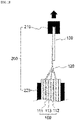
- FIG. 2 is a schematic diagram illustrating a method of measuring a tensile strength in a method of inspecting a welding defect according to the present invention
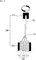
- FIG. 3 is a schematic diagram illustrating a method of measuring a torsional strength in a method of inspecting a welding defect according to the present invention
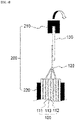
- FIG. 4 is a schematic diagram illustrating a method of measuring a peeling strength in a method of inspecting a welding defect according to the present invention.
- an electrode assembly 100 has a structure in which a positive electrode 111, a negative electrode 112 and a separator 113 are alternately stacked.
- an electrode tab 120 which is one of a positive electrode tab and a negative electrode tab, is formed at one side of the electrode assembly 100, and an electrode lead 130 is joined to the electrode tab by welding.
- the measuring apparatus 200 includes a first gripper 210 configured to fix the end of the electrode lead; and a second gripper 220 configured to fix the electrode assembly.
- the second gripper 220 fixes the electrode assembly 100.
- the second gripper 220 may have a structure that one pair of pressing plates are formed on surfaces contacting the electrode assembly 100 to press the electrode assembly 110 from two surfaces.
- the one pair of pressing plates may be fixed by appropriately pressing the electrode assembly through interval adjustment.
- the first gripper 210 may have a structure in which a space for accommodating the electrode lead 130 is formed to fix the end of the electrode lead 130, for example, a structure in which one pair of pressing plates are formed on the surface contacting the electrode lead. In this case, the pressing plate may appropriately adjust the interval to thereby fix the electrode lead.
- the first gripper 210 and the second gripper 220 may fix the electrode assembly and the electrode lead and there is no specific limitation on their form.
- the first gripper 210 applies force to the electrode lead in a predetermined direction to thereby break the welded portion.
- the first gripper 210 may apply tensile force to the welded portion between the electrode lead 130 and the electrode tab 120 by pulling the electrode lead 130 to be parallel to the drawn direction.
- the first gripper 210 may pull the electrode lead 130 until the welded portion is broken, and the force, which is applied to the welded portion at the time of breakage, may be defined as the tensile strength of the welded portion.
- the force, which is applied to the welded portion at the time of breakage may be measured using a known measuring device, etc.
- the first gripper 210 may apply torsional force to the welded portion between the electrode lead 130 and the electrode tab 120 by rotating by using the central portion in the width direction of the electrode lead as the rotation shaft.
- the first gripper 210 rotate until the welded portion is broken, and the force, which is applied to the welded portion at the time of breakage, may be defined as the torsional strength of the welded portion.
- the force, which is applied to the welded portion at the time of breakage may be measured using a known measuring device, etc.
- the first gripper 210 may apply force to peel off the electrode lead 130 from the electrode tab 120 while applying force in a direction perpendicular to a direction in which the electrode tab 120 or the electrode lead 130 are drawn.
- the first gripper 210 may apply force until the welded portion is broken, and the force, which is applied to the welded portion at the time of breakage, may be defined as the peeling strength of the welded portion.
- the force, which is applied to the welded portion at the time of breakage may be measured using a known measuring device, etc.
- the welding strength may be measured for each of a plurality of electrode assembly samples, and as will be described later, the welding strength may be measured for electrode assembly samples by different welding methods.
- the correlation between whether there is a welding defect and each of the tensile strength, the torsional strength, and the peeling strength is derived.
- the correlation refers to a tendency indicated by whether there is a welding defect according to the numerical value of the tensile strength, the torsional strength and the peeling strength.
- the deriving of the correlation includes making a database about the correlation between the tensile strength, the torsional strength and the peeling strength of the welded portion between the electrode tab and the electrode lead and whether there is a welding defect. This is to recognize the tendency of whether there is a welding defect for the tensile strength, the torsional strength and the peeling strength.
- the tensile strength, the torsional strength and the peeling strength are respectively measured after manufacturing a plurality of electrode assembly samples, and the measured information may be saved in a storage system such as a memory. Further, such a database may be recorded in visual data such as tables or graphs. At this time, it is preferable to measure the tensile strength, the torsional strength and the peeling strength for a large number of electrode assembly samples for the accuracy of the measurement.
- whether there is a welding defect indicates whether there has actually been a defect at a welded portion between an electrode lead and an electrode tab. For example, it may be determined by observing the external appearance of the welded portion or the surface state of the welded portion.
- reference values for determining whether there is a welding defect are derived therefrom.
- the reference value is derived from the database.
- the reference value is derived for each of the tensile strength, the torsional strength and the peeling strength.
- the measurement value information for the tensile strength, the torsional strength and the peeling strength of electrode assembly samples determined as having a welding defect, and the measurement value information for the tensile strength, the torsional strength and the peeling strength of electrode assembly samples determined as having no welding defect are saved in the database.
- the minimum value among the measurement values for the tensile strength, the torsional strength and the peeling strength of the electrode assembly samples determined as having no welding defect may be determined as the reference value.
- the inspection method can be applied all welding processes by checking the correlation between whether there is a welding defect and each of the tensile strength, the torsional strength, and the peeling strength and standardizing the correlation.
- the welding strength by measuring other strength values in addition to the tensile strength and deriving the reference value therefrom, it is possible to detect small welding defects, and the reliability and accuracy of the welding may be improved.
- the method of inspecting a welding defect includes measuring the tensile strength, the torsional strength and the peeling strength of the welded portion between the electrode tab and the electrode lead by using different welding methods, and deriving correlation between whether there is a welding defect and each of the tensile strength, the torsional strength, and the peeling strength for each of the welding methods. Further, the welding defect inspection method further includes deriving a reference value for determining whether there is a welding defect for each of the welding methods.
- FIG. 5 is a flowchart illustrating the order of a method of inspecting a welding defect according to another embodiment of the present invention.
- a method of inspecting a welding defect includes: manufacturing an electrode assembly sample by welding an electrode lead on an electrode tab formed on an electrode assembly (S20); measuring a tensile strength, a torsional strength and a peeling strength of a welded portion between the electrode tab and the electrode lead for the electrode assembly sample by using different welding methods (S21); deriving correlation between whether there is a welding defect and each of the tensile strength, the torsional strength, and the peeling strength (S22); and deriving a reference value for determining whether there is a welding defect for each of the welding methods (S23).
- the welding methods may include laser welding and ultrasonic welding.
- the present invention may reflect deviation of the welding strength which may vary according to the welding method by differentiating the reference value according to the welding method in the process of deriving the reference value for determining whether there is a welding defect.
- each step in the welding defect inspection method is the same as described above. Specifically, three sets of electrode assembly samples are prepared using one welding method, and then one of the tensile strength, the torsional strength and the peeling strength is measured for each set. Further, the same process is repeated using different welding methods.
- the measuring apparatus may include a first gripper configured to fix the end of the electrode lead, and a second gripper configured to fix the electrode assembly.
- the correlation between whether there is a welding defect and each of the tensile strength, the torsional strength, and the peeling strength for each welding method is derived from the measured welding strength.
- the tensile strength, the torsional strength and the peeling strength are respectively measured after manufacturing a plurality of electrode assembly samples using different welding methods, and the measured information may be saved in a storage system such as a memory. Further, such a database may be recorded in visual data such as tables or graphs. Further, the reference value may be derived from such a database. The specific process for deriving the reference value may be the same as described above.
- the method of inspecting a welding defect according to the present invention further includes determining a cause of generation of a welding defect from the correlation and making a database based thereon.
- causes of welding defects are also different.
- the tensile strength, the torsional strength and the peeling strength according to the welding method and the cause of the welding defect may be made as a database, and the database may be utilized as reference data for finding out the cause of the welding defect when such a welding defect occurs.
- the step of determining whether there is a welding defect in the electrode assembly is performed based thereon.
- the step of determining whether there is a welding defect includes preparing three sets of electrode assemblies to be inspected by welding an electrode lead on an electrode tab, measuring one of the tensile strength, the torsional strength and the peeling strength for each set, and comparing the measurement value with the reference value to determine whether there is a welding defect.
- the method of manufacturing the electrode assembly and the method of measuring the tensile strength, the torsional strength and the peeling strength are the same as described above.
- the tensile strength, the torsional strength and the peeling strength may be measured by a measuring apparatus described above, and a different welding strength may be measured per set.
- the determining of whether is a welding defect includes comparing the measured value with the reference value for two of the tensile strength, the torsional strength and the peeling strength.
- the measurement value is compared with the reference value for any two of the tensile strength, the torsional strength and the peeling strength, and if the measurement value satisfies the reference value requirement for the two, the electrode assembly may be determined as a good product.
- the electrode assembly determined as a good product may be an electrode assembly manufactured in the same process line.
- the determining of whether is a welding defect includes comparing the measured value with the reference value for the tensile strength, the torsional strength and the peeling strength.
- the measurement value is compared with the reference value for all of the tensile strength, the torsional strength and the peeling strength, and if the measurement value satisfies the reference value requirement for all of the tensile strength, the torsional strength and the peeling strength, the electrode assembly may be determined as a good product.
- the electrode assembly determined as a good product may be an electrode assembly manufactured in the same process line.
- the present invention provides a method of manufacturing a secondary battery including the method of inspecting a welding defect as described above.
- the secondary battery is manufactured as an electrode assembly having a structure, in which a positive electrode, a separator and a negative electrode are alternately stacked, is accommodated in a battery case.
- the same as the above-described electrode assembly sample may be used as the positive electrode, the negative electrode and the separator.
- what was determined as a good product when performing inspection according to the welding defect inspection method as described above may be used as the electrode assembly.
- the battery case is not particularly limited as long as it is used as an exterior material for packaging the battery, and a cylindrical, square, or pouch type may be used and specifically a pouch-type battery case may be used. Likewise, details about the battery case are known to those of ordinary skill in the art, and thus the detailed description thereof is omitted here.
- an electrolyte solution is injected and the battery case is sealed, and then a formation process is performed, to thereby manufacture a secondary battery.
Landscapes
- Chemical & Material Sciences (AREA)
- Health & Medical Sciences (AREA)
- Life Sciences & Earth Sciences (AREA)
- Analytical Chemistry (AREA)
- Pathology (AREA)
- Physics & Mathematics (AREA)
- Immunology (AREA)
- Biochemistry (AREA)
- General Health & Medical Sciences (AREA)
- General Physics & Mathematics (AREA)
- Engineering & Computer Science (AREA)
- Food Science & Technology (AREA)
- Medicinal Chemistry (AREA)
- General Chemical & Material Sciences (AREA)
- Electrochemistry (AREA)
- Chemical Kinetics & Catalysis (AREA)
- Crystallography & Structural Chemistry (AREA)
- Manufacturing & Machinery (AREA)
- Quality & Reliability (AREA)
- Mechanical Engineering (AREA)
- Connection Of Batteries Or Terminals (AREA)
- Secondary Cells (AREA)
Abstract
Description
- This application claims the benefit of priority based on
Korean Patent Application No. 10-2020-0105340, filed on August 21, 2020 - The present invention relates to a method of inspecting a welding defect and a method of manufacturing a secondary battery including the method.
- Recently, secondary batteries capable of charging and discharging have been widely used as energy sources of wireless mobile devices. In addition, the secondary battery has attracted attention as an energy source of an electric vehicle, a hybrid electric vehicle, etc., which are proposed as a solution for air pollution of existing gasoline vehicles and diesel vehicles using fossil fuel. Therefore, the types of applications using the secondary battery are currently much diversified due to the advantages of the secondary battery, and it is expected that the secondary battery will be applied to many fields and products in the future.
- Such secondary batteries may be classified into lithium ion batteries, lithium ion polymer batteries, lithium polymer batteries, etc., depending on the composition of the electrode and the electrolyte, and among them, the amount of use of lithium-ion polymer batteries that are less likely to leak electrolyte and are easy to manufacture is on the increase. In general, secondary batteries are classified into cylindrical batteries and prismatic batteries in which an electrode assembly is embedded in a cylindrical or rectangular metal can, depending on the shape of a battery case, and pouch-type batteries in which the electrode assembly is embedded in a pouch-type case of an aluminum laminate sheet. The electrode assembly built into the battery case is composed of a positive electrode, a negative electrode, and a separator interposed between the positive electrode and the negative electrode, and is a power generating element capable of charging and discharging. The electrode assembly is classified into a jelly-roll type wound with a separator interposed between the positive electrode and the negative electrode which are long sheet-shaped and are coated with active materials, and a stack type in which a plurality of positive electrodes and negative electrodes of a predetermined size are sequentially stacked while a separator is interposed therebetween.
- The positive electrode and the negative electrode are formed by applying a positive electrode slurry containing a positive electrode active material and a negative electrode slurry containing a negative electrode active material to a positive electrode current collector and a negative electrode current collector, followed by drying and rolling them. At this time, a little amount of binder is added to the positive electrode slurry and the negative electrode slurry to prevent the active material from being deintercalated from the current collector.
- Further, a positive electrode tab and a negative electrode tab are formed at the positive electrode and the negative electrode for electric connection, and a positive electrode lead and a negative electrode lead are formed at the positive electrode tab and the negative electrode tab, respectively. At this time, the positive electrode tab and the positive electrode lead may be joined by welding, and the negative electrode tab and the negative electrode lead may also be joined by welding. At this time, since a welding defect may occur between the tab and the lead, welding defect inspection is performed to detect the welding defect.
- When the welding defect inspection is performed, a welding strength of a welded portion between a tab and lead is generally measured. To this end, the tensile strength of the welded portion between the tab and the lead is mainly measured. Specifically, the tensile strength, which is generated as the tab and the lead are tensed in an opposite direction, is measured.
- However, it is difficult to detect welding defects of all cases and intermittently generated small welding defects using only the tensile strength.
- Hence, it is necessary to develop a method of inspecting a welding defect capable of detecting all small welding defects.
- The present invention has been made to solve the above problems, and an object of the present invention is to provide a method of inspecting a welding defect having improved welding reliability and accuracy by detecting all small welding defects.
- A method of inspecting a welding defect according to an embodiment of the present invention includes: manufacturing an electrode assembly sample by welding an electrode lead on an electrode tab formed on an electrode assembly; measuring a tensile strength, a torsional strength and a peeling strength of a welded portion between the electrode tab and the electrode lead for the electrode assembly sample; deriving correlation between whether there is a welding defect and each of the tensile strength, the torsional strength, and the peeling strength; and deriving a reference value for determining whether there is a welding defect for the tensile strength, the torsional strength, and the peeling strength, respectively.
- In a specific example, the measuring of the tensile strength, the torsional strength and the peeling strength includes: preparing three sets of electrode assembly samples; and measuring any one of the tensile strength, the torsional strength and the peeling strength per set.
- The tensile strength, the tensile strength and the peeling strength are measured using a measuring apparatus including: a first gripper configured to fix an end of the electrode lead; and a second gripper configured to fix the electrode assembly.
- At this time, the first gripper applies force to the electrode lead in a predetermined direction to thereby break the welded portion.
- Further, in an embodiment of the present invention, the deriving of the correlation includes making a database about the correlation between the tensile strength, the torsional strength and the peeling strength of the welded portion between the electrode tab and the electrode lead and whether there is a welding defect.
- At this time, the reference value is derived from the database.
- In another embodiment of the present invention, the method of inspecting a welding defect further includes measuring the tensile strength, the torsional strength and the peeling strength of the welded portion between the electrode tab and the electrode lead by using different welding methods, and deriving correlation between whether there is a welding defect and each of the tensile strength, the torsional strength, and the peeling strength for each of the welding methods.
- At this time, the method of inspecting a welding defect according to the present invention further includes deriving a reference value for determining whether there is a welding defect for each of the welding methods.
- The welding methods include a ultrasonic welding or a laser welding.
- The method of inspecting a welding defect according to the present invention further includes determining a cause of generation of a welding defect from the correlation and making a database based thereon.
- Further, the method of inspecting a welding defect according to the present invention further includes determining a welding defect of the electrode assembly.
- At this time, the determining of the welding defect includes: preparing three sets of electrode assemblies to be inspected by welding electrode leads on electrode tabs; measuring any one of a tensile strength, a torsional strength, and a peeling strength for each set; and determining whether there is a welding defect by comparing a measured value obtained by the measuring with a reference value.
- At this time, the determining of whether is a welding defect includes comparing the measured value with the reference value for two of the tensile strength, the torsional strength and the peeling strength.
- Further, the determining of whether is a welding defect includes comparing the measured value with the reference value for the tensile strength, the torsional strength and the peeling strength.
- Further, the present invention provides a method of manufacturing a secondary battery including the method of inspecting a welding defect as described above.
- According to the welding defect inspection method of the present invention, the inspection method can be applied all welding processes by checking the correlation between whether there is a welding defect and each of the tensile strength, the torsional strength, and the peeling strength and standardizing the correlation.
- Further, with respect to the welding strength, by measuring other strength values in addition to the tensile strength and deriving the reference value therefrom, it is possible to detect small welding defects, and the reliability and accuracy of the welding may be improved.
-
-
FIG. 1 is a flowchart illustrating the order of a method of inspecting a welding defect according to an embodiment of the present invention. -
FIG. 2 is a schematic diagram illustrating a method of measuring a tensile strength in a method of inspecting a welding defect according to the present invention. -
FIG. 3 is a schematic diagram illustrating a method of measuring a torsional strength in a method of inspecting a welding defect according to the present invention. -
FIG. 4 is a schematic diagram illustrating a method of measuring a peeling strength in a method of inspecting a welding defect according to the present invention. -
FIG. 5 is a flowchart illustrating the order of a method of inspecting a welding defect according to another embodiment of the present invention. - Hereinafter, the present invention will be described in detail with reference to the drawings. The terms and words used in the present specification and claims should not be construed as limited to ordinary or dictionary terms and the inventor may properly define the concept of the terms in order to best describe its invention. The terms and words should be construed as meaning and concept consistent with the technical idea of the present invention.
- In this application, it should be understood that terms such as "include" or "have" are intended to indicate that there is a feature, number, step, operation, component, part, or a combination thereof described on the specification, and they do not exclude in advance the possibility of the presence or addition of one or more other features or numbers, steps, operations, components, parts or combinations thereof. Also, when a portion such as a layer, a film, an area, a plate, etc. is referred to as being "on" another portion, this includes not only the case where the portion is "directly on" the another portion but also the case where further another portion is interposed therebetween. On the other hand, when a portion such as a layer, a film, an area, a plate, etc. is referred to as being "under" another portion, this includes not only the case where the portion is "directly under" the another portion but also the case where further another portion is interposed therebetween. In addition, to be disposed "on" in the present application may include the case disposed at the bottom as well as the top.
- Hereinafter, the present invention will be described in detail with reference to the drawings.
-
FIG. 1 is a flowchart illustrating the order of a method of inspecting a welding defect according to an embodiment of the present invention. - Referring to
FIG. 1 , a method of inspecting a welding defect according to an embodiment of the present invention includes: manufacturing an electrode assembly sample by welding an electrode lead on an electrode tab formed on an electrode assembly (S10); measuring a tensile strength, a torsional strength and a peeling strength of a welded portion between the electrode tab and the electrode lead for the electrode assembly sample (S20); deriving correlation between whether there is a welding defect and each of the tensile strength, the torsional strength, and the peeling strength (S30); and deriving a reference value for determining whether there is a welding defect for the tensile strength, the torsional strength, and the peeling strength, respectively (S40). - As described above, the tensile strength of the welded portion between the tab and the lead was measured for a general welding defect inspection. However, since the welding strength for only one direction can be recognized by such a tensile strength inspection, it is difficult to detect welding defects of all cases and intermittently generated small welding defects.
- According to the welding defect inspection method of the present invention, the inspection method can be applied all welding processes by checking the correlation between the tensile strength, the torsional strength and the peeling strength as the welding strength and whether there is a welding defect and standardizing the correlation.
- Further, with respect to the welding strength, by measuring other strength values in addition to the tensile strength and deriving the reference value therefrom, it is possible to detect small welding defects, and the reliability and accuracy of the welding may be improved.
- Hereinafter, each step of the welded defect inspection method according to the present invention will be described in detail.
- In the specification of the present invention, the welding strength includes a tensile strength, a torsional strength, and a peeling strength as the strength at a welded portion between an electrode tab and an electrode lead.
- In the welding defect inspection method according to the present invention, an electrode assembly sample is manufactured by welding an electrode lead on an electrode tab formed on an electrode assembly.
- At this time, the electrode assembly has a structure in which a positive electrode, a separator and a negative electrode are alternately stacked, and the positive electrode and the negative electrode may respectively have a structure in which an active material layer is formed through the drying and rolling process after an electrode slurry containing an electrode active material is applied on a current collector.
- The current collector may be a positive electrode current collector or a negative electrode current collector, and the electrode active material may be a positive electrode active material or a negative electrode active material. In addition, the electrode slurry may further include a conductive material and a binder in addition to the electrode active material.
- In the present invention, the positive electrode collector generally has a thickness of 3 to 500 micrometers. The positive electrode current collector is not particularly limited as long as it has high conductivity without causing a chemical change in the battery. Examples of the positive electrode current collector include stainless steel, aluminum, nickel, titanium, sintered carbon or aluminum or stainless steel of which the surface has been treated with carbon, nickel, titanium, silver, or the like. The current collector may have fine irregularities on the surface thereof to increase the adhesion of the positive electrode active material, and various forms such as a film, a sheet, a foil, a net, a porous body, a foam, and a nonwoven fabric are possible.
- The sheet for the negative electrode collector generally has a thickness of 3 to 500 micrometers. The negative electrode current collector is not particularly limited as long as it has electrical conductivity without causing chemical changes in the battery, and examples thereof include copper, stainless steel, aluminum, nickel, titanium, sintered carbon, copper or stainless steel of which the surface has been treated with carbon, nickel, titanium, silver or the like, aluminum-cadmium alloy, or the like. In addition, like the positive electrode current collector, fine unevenness can be formed on the surface to enhance the bonding force of the negative electrode active material, and it can be used in various forms such as a film, a sheet, a foil, a net, a porous body, a foam, and a nonwoven fabric.
- In the present invention, the positive electrode active material is a material capable of causing an electrochemical reaction and a lithium transition metal oxide, and contains two or more transition metals. Examples thereof include: layered compounds such as lithium cobalt oxide (LiCoO2) and lithium nickel oxide (LiNiO2) substituted with one or more transition metals; lithium manganese oxide substituted with one or more transition metals; lithium nickel oxide represented by the formula LiNi1-yMyO2 (wherein M = Co, Mn, Al, Cu, Fe, Mg, B, Cr, Zn or Ga and contains at least one of the above elements, 0.01 ≦ y ≦ 0.7); lithium nickel cobalt manganese composite oxide represented by the formula Li1+zNibMncCo1-(b+c+d)MdO(2-e)Ae such as Li1+zNi1/3Co1/3Mn1/3O2, Li1+zNi0.4Mn0.4Co0.2O2 etc. (wherein - 0.5≤z≤0.5, 0.1≤b≤0.8, 0.1≤c≤0.8, 0≤d≤0.2, 0≤e≤0.2, b+c+d<1, M = Al, Mg, Cr, Ti, Si or Y, and A = F, P or Cl); olivine-based lithium metal phosphate represented by the formula Li1+xM1-yM'yPO4-zXz (wherein M = transition metal, preferably Fe, Mn, Co or Ni, M'= Al, Mg or Ti, X = F, S or N, and -0.5≤x≤0.5, 0≤y≤0.5, 0≤z≤0.1).
- Examples of the negative electrode active material include carbon such as non-graphitized carbon and graphite carbon; metal complex oxide such as LixFe2O3(0≤x≤1), LixWO2(0≤x≤1), SnxMe1-xMe'yOz (Me: Mn, Fe, Pb, Ge; Me': Al, B, P, Si, groups 1, 2, and 3 of the periodic table, halogen; 0<x≤1; 1≤y≤3; 1≤z≤8); lithium alloy; silicon alloy; tin alloy; metal oxides such as SnO, SnO2, PbO, PbO2, Pb2O3, Pb3O4, Sb2O3, Sb2O4, Sb2O5, GeO, GeO2, Bi2O3, Bi2O4, and Bi2O5; conductive polymers such as polyacetylene; and Li-Co-Ni-based materials.
- The conductive material is usually added in an amount of 1 to 30% by weight based on the total weight of the mixture including the positive electrode active material. Such a conductive material is not particularly limited as long as it has electrical conductivity without causing a chemical change in the battery, and examples thereof include graphite such as natural graphite and artificial graphite; carbon black such as carbon black, acetylene black, Ketjen black, channel black, furnace black, lamp black, and summer black; conductive fibers such as carbon fiber and metal fiber; metal powders such as carbon fluoride, aluminum and nickel powder; conductive whiskey such as zinc oxide and potassium titanate; conductive metal oxides such as titanium oxide; and conductive materials such as polyphenylene derivatives and the like.
- The binder is added in an amount of 1 to 30% by weight, on the basis of the total weight of the mixture containing the positive electrode active material, as a component that assists in bonding between the active material and the conductive material and bonding to the current collector. Examples of such binders include polyvinylidene fluoride, polyvinyl alcohol, carboxymethylcellulose (CMC), starch, hydroxypropylcellulose, regenerated cellulose, polyvinylpyrrolidone, tetrafluoroethylene, polyethylene, polypropylene, ethylenepropylene-diene terpolymer (EPDM), sulfonated EPDM, styrene butylene rubber, fluorine rubber, various copolymers and the like.
- Further, the separator is interposed between the positive electrode and the negative electrode, and an insulating thin film having high ion permeability and mechanical strength is used. The pore diameter of the separator is generally 0.01 to 10 micrometers, and the thickness is generally 5 to 300 micrometers. Examples of such a separator include olefin-based polymers such as polypropylene which is chemically resistant and hydrophobic; a sheet or a nonwoven fabric made of glass fiber, polyethylene or the like.
- In an electrode assembly, an electrode tab is formed at one side of an electrode, and the electrode tab may be a positive electrode tab or a negative electrode tab. A positive electrode lead and a negative electrode lead are connected to the positive electrode tab and the negative electrode tab, respectively. The positive electrode lead and the negative electrode lead are drawn to the outside to thereby play a role of a terminal which is electrically connected to the outside. At this time, the positive electrode lead and the negative electrode lead may be joined to the positive electrode tab and the negative electrode tab, respectively, by welding. Known welding methods may be used. For example, a ultrasonic welding or a laser welding may be used.
- When an electrode assembly sample is manufactured, the welding strength, that is, the tensile strength, the torsional strength and the peeling strength, of the welded portion is measured for the electrode assembly sample. In the welding defect inspection method according to the present invention, two or more kinds of welding strength may be measured according to the direction of the external force.
- Namely, according to the welding defect inspection method of the present invention, it is possible to detect all small welding defects by adding the torsional strength and the peeling strength, which are measured as external force in a direction that is different from that of the tensile strength is applied, in addition to the tensile strength, as the evaluation standard for determining the welding defect, thereby improving reliability and accuracy of welding.
- The measuring of the tensile strength, the torsional strength and the peeling strength includes: preparing three sets of electrode assembly samples; and measuring any one of the tensile strength, the torsional strength and the peeling strength per set.
- As will be described later, the tensile strength, the torsional strength and the peeling strength are measured by breaking a welded portion between an electrode tab and an electrode lead by applying external force to the electrode tab in a constant direction. As such, it is not possible to measure a different kind of welding strength with the electrode assembly sample which has already been measured for one kind of welding strength. Hence, three sets are prepared, and one of the tensile strength, the torsional strength and the peeling strength is measured for each set. Herein, one set includes at least one electrode assembly sample, and one set may include two or more electrode assembly samples. At this time, if one set includes two or more electrode assembly samples, the average of welding strengths of two electrode assembly samples may be determined as the welding strength of the set.
- Further, the tensile strength, the torsional strength and the peeling strength may be measured using the same form of measuring apparatus.
-
FIG. 2 is a schematic diagram illustrating a method of measuring a tensile strength in a method of inspecting a welding defect according to the present invention, andFIG. 3 is a schematic diagram illustrating a method of measuring a torsional strength in a method of inspecting a welding defect according to the present invention.FIG. 4 is a schematic diagram illustrating a method of measuring a peeling strength in a method of inspecting a welding defect according to the present invention. - Referring to
FIGS. 2 to 4 , anelectrode assembly 100 has a structure in which apositive electrode 111, anegative electrode 112 and aseparator 113 are alternately stacked. Herein, anelectrode tab 120, which is one of a positive electrode tab and a negative electrode tab, is formed at one side of theelectrode assembly 100, and anelectrode lead 130 is joined to the electrode tab by welding. - Further, the measuring
apparatus 200 includes afirst gripper 210 configured to fix the end of the electrode lead; and asecond gripper 220 configured to fix the electrode assembly. - Specifically, the
second gripper 220 fixes theelectrode assembly 100. Thesecond gripper 220 may have a structure that one pair of pressing plates are formed on surfaces contacting theelectrode assembly 100 to press the electrode assembly 110 from two surfaces. The one pair of pressing plates may be fixed by appropriately pressing the electrode assembly through interval adjustment. - The
first gripper 210 may have a structure in which a space for accommodating theelectrode lead 130 is formed to fix the end of theelectrode lead 130, for example, a structure in which one pair of pressing plates are formed on the surface contacting the electrode lead. In this case, the pressing plate may appropriately adjust the interval to thereby fix the electrode lead. In the present invention, thefirst gripper 210 and thesecond gripper 220 may fix the electrode assembly and the electrode lead and there is no specific limitation on their form. - At this time, the
first gripper 210 applies force to the electrode lead in a predetermined direction to thereby break the welded portion. - Referring to
FIG. 2 , thefirst gripper 210 may apply tensile force to the welded portion between theelectrode lead 130 and theelectrode tab 120 by pulling theelectrode lead 130 to be parallel to the drawn direction. Thefirst gripper 210 may pull theelectrode lead 130 until the welded portion is broken, and the force, which is applied to the welded portion at the time of breakage, may be defined as the tensile strength of the welded portion. The force, which is applied to the welded portion at the time of breakage, may be measured using a known measuring device, etc. - Referring to
FIG. 3 , thefirst gripper 210 may apply torsional force to the welded portion between theelectrode lead 130 and theelectrode tab 120 by rotating by using the central portion in the width direction of the electrode lead as the rotation shaft. Thefirst gripper 210 rotate until the welded portion is broken, and the force, which is applied to the welded portion at the time of breakage, may be defined as the torsional strength of the welded portion. Likewise, the force, which is applied to the welded portion at the time of breakage, may be measured using a known measuring device, etc. - Referring to
FIG. 4 , thefirst gripper 210 may apply force to peel off theelectrode lead 130 from theelectrode tab 120 while applying force in a direction perpendicular to a direction in which theelectrode tab 120 or theelectrode lead 130 are drawn. Thefirst gripper 210 may apply force until the welded portion is broken, and the force, which is applied to the welded portion at the time of breakage, may be defined as the peeling strength of the welded portion. Likewise, the force, which is applied to the welded portion at the time of breakage, may be measured using a known measuring device, etc. - The welding strength may be measured for each of a plurality of electrode assembly samples, and as will be described later, the welding strength may be measured for electrode assembly samples by different welding methods.
- When the a tensile strength, a torsional strength and a peeling strength are measured for an electrode assembly sample, the correlation between whether there is a welding defect and each of the tensile strength, the torsional strength, and the peeling strength is derived. Herein, the correlation refers to a tendency indicated by whether there is a welding defect according to the numerical value of the tensile strength, the torsional strength and the peeling strength.
- Specifically, the deriving of the correlation includes making a database about the correlation between the tensile strength, the torsional strength and the peeling strength of the welded portion between the electrode tab and the electrode lead and whether there is a welding defect. This is to recognize the tendency of whether there is a welding defect for the tensile strength, the torsional strength and the peeling strength. To this end, the tensile strength, the torsional strength and the peeling strength are respectively measured after manufacturing a plurality of electrode assembly samples, and the measured information may be saved in a storage system such as a memory. Further, such a database may be recorded in visual data such as tables or graphs. At this time, it is preferable to measure the tensile strength, the torsional strength and the peeling strength for a large number of electrode assembly samples for the accuracy of the measurement.
- Herein, whether there is a welding defect indicates whether there has actually been a defect at a welded portion between an electrode lead and an electrode tab. For example, it may be determined by observing the external appearance of the welded portion or the surface state of the welded portion.
- After deriving the correlation between whether there is a welding defect and each of the tensile strength, the torsional strength, and the peeling strength, reference values for determining whether there is a welding defect are derived therefrom. The reference value is derived from the database. Herein, the reference value is derived for each of the tensile strength, the torsional strength and the peeling strength.
- Specifically, the measurement value information for the tensile strength, the torsional strength and the peeling strength of electrode assembly samples determined as having a welding defect, and the measurement value information for the tensile strength, the torsional strength and the peeling strength of electrode assembly samples determined as having no welding defect, are saved in the database. Herein, for example, the minimum value among the measurement values for the tensile strength, the torsional strength and the peeling strength of the electrode assembly samples determined as having no welding defect may be determined as the reference value.
- Namely, according to the welding defect inspection method of the present invention, the inspection method can be applied all welding processes by checking the correlation between whether there is a welding defect and each of the tensile strength, the torsional strength, and the peeling strength and standardizing the correlation.
- Further, with respect to the welding strength, by measuring other strength values in addition to the tensile strength and deriving the reference value therefrom, it is possible to detect small welding defects, and the reliability and accuracy of the welding may be improved.
- Further, in another embodiment of the present invention, the method of inspecting a welding defect includes measuring the tensile strength, the torsional strength and the peeling strength of the welded portion between the electrode tab and the electrode lead by using different welding methods, and deriving correlation between whether there is a welding defect and each of the tensile strength, the torsional strength, and the peeling strength for each of the welding methods. Further, the welding defect inspection method further includes deriving a reference value for determining whether there is a welding defect for each of the welding methods.
-
FIG. 5 is a flowchart illustrating the order of a method of inspecting a welding defect according to another embodiment of the present invention. - Namely, referring to
FIG. 5 , a method of inspecting a welding defect includes:
manufacturing an electrode assembly sample by welding an electrode lead on an electrode tab formed on an electrode assembly (S20); measuring a tensile strength, a torsional strength and a peeling strength of a welded portion between the electrode tab and the electrode lead for the electrode assembly sample by using different welding methods (S21); deriving correlation between whether there is a welding defect and each of the tensile strength, the torsional strength, and the peeling strength (S22); and deriving a reference value for determining whether there is a welding defect for each of the welding methods (S23). - Herein, the welding methods may include laser welding and ultrasonic welding.
- Namely, the present invention may reflect deviation of the welding strength which may vary according to the welding method by differentiating the reference value according to the welding method in the process of deriving the reference value for determining whether there is a welding defect.
- Herein, each step in the welding defect inspection method is the same as described above. Specifically, three sets of electrode assembly samples are prepared using one welding method, and then one of the tensile strength, the torsional strength and the peeling strength is measured for each set. Further, the same process is repeated using different welding methods.
- At this time, the measuring apparatus may include a first gripper configured to fix the end of the electrode lead, and a second gripper configured to fix the electrode assembly.
- Meanwhile, when the welding strength is measured, the correlation between whether there is a welding defect and each of the tensile strength, the torsional strength, and the peeling strength for each welding method is derived from the measured welding strength. At this time, a step of determining the cause of generation of a welding defect from the tensile strength, the torsional strength and the peeling strength according to the welding method and making a database based thereon. To this end, the tensile strength, the torsional strength and the peeling strength are respectively measured after manufacturing a plurality of electrode assembly samples using different welding methods, and the measured information may be saved in a storage system such as a memory. Further, such a database may be recorded in visual data such as tables or graphs. Further, the reference value may be derived from such a database. The specific process for deriving the reference value may be the same as described above.
- Further, the method of inspecting a welding defect according to the present invention further includes determining a cause of generation of a welding defect from the correlation and making a database based thereon. When different welding methods are used, causes of welding defects are also different. Hence, in the present invention, the tensile strength, the torsional strength and the peeling strength according to the welding method and the cause of the welding defect may be made as a database, and the database may be utilized as reference data for finding out the cause of the welding defect when such a welding defect occurs.
- Likewise, when the reference value for whether there is a welding defect is secured, the step of determining whether there is a welding defect in the electrode assembly is performed based thereon.
- The step of determining whether there is a welding defect includes preparing three sets of electrode assemblies to be inspected by welding an electrode lead on an electrode tab, measuring one of the tensile strength, the torsional strength and the peeling strength for each set, and comparing the measurement value with the reference value to determine whether there is a welding defect.
- Specifically, the method of manufacturing the electrode assembly and the method of measuring the tensile strength, the torsional strength and the peeling strength are the same as described above. The tensile strength, the torsional strength and the peeling strength may be measured by a measuring apparatus described above, and a different welding strength may be measured per set.
- When the tensile strength, the torsional strength and the peeling strength are measured, they are compared with the reference value to determine whether there is a welding defect. At this time, the determining of whether is a welding defect includes comparing the measured value with the reference value for two of the tensile strength, the torsional strength and the peeling strength. In this case, for example, the measurement value is compared with the reference value for any two of the tensile strength, the torsional strength and the peeling strength, and if the measurement value satisfies the reference value requirement for the two, the electrode assembly may be determined as a good product. In this case, the electrode assembly determined as a good product may be an electrode assembly manufactured in the same process line.
- Further, in another example, the determining of whether is a welding defect includes comparing the measured value with the reference value for the tensile strength, the torsional strength and the peeling strength. In this case, for example, the measurement value is compared with the reference value for all of the tensile strength, the torsional strength and the peeling strength, and if the measurement value satisfies the reference value requirement for all of the tensile strength, the torsional strength and the peeling strength, the electrode assembly may be determined as a good product. As described above, the electrode assembly determined as a good product may be an electrode assembly manufactured in the same process line.
- Further, the present invention provides a method of manufacturing a secondary battery including the method of inspecting a welding defect as described above.
- Specifically, the secondary battery is manufactured as an electrode assembly having a structure, in which a positive electrode, a separator and a negative electrode are alternately stacked, is accommodated in a battery case. At this time, the same as the above-described electrode assembly sample may be used as the positive electrode, the negative electrode and the separator. Further, what was determined as a good product when performing inspection according to the welding defect inspection method as described above may be used as the electrode assembly.
- Further, the battery case is not particularly limited as long as it is used as an exterior material for packaging the battery, and a cylindrical, square, or pouch type may be used and specifically a pouch-type battery case may be used. Likewise, details about the battery case are known to those of ordinary skill in the art, and thus the detailed description thereof is omitted here.
- When an electrode assembly is accommodated in a battery case, an electrolyte solution is injected and the battery case is sealed, and then a formation process is performed, to thereby manufacture a secondary battery.
- The above description is merely illustrative of the technical idea of the present invention, and those skilled in the art to which the present invention pertains may make various modifications and variations without departing from the essential characteristics of the present invention. Therefore, the drawings disclosed in the present invention are not intended to limit the technical idea of the present invention but to describe the present invention, and the scope of the technical idea of the present invention is not limited by these drawings. The scope of protection of the present invention should be interpreted by the following claims, and all technical ideas within the scope equivalent thereto should be construed as being included in the scope of the present invention.
- On the other hand, in this specification, terms indicating directions such as up, down, left, right, before, and after are used, but it is obvious that these terms are for convenience of description only and may change depending on the location of the object or the location of the observer.
-
- 100: electrode assembly
- 111: positive electrode
- 112: negative electrode
- 113: separator
- 120: electrode tab
- 130: electrode lead
- 200: measuring apparatus
- 210: first gripper
- 220: second gripper
Claims (15)
- A method of inspecting a welding defect, the method comprising:manufacturing an electrode assembly sample by welding an electrode lead on an electrode tab formed on an electrode assembly;measuring a tensile strength, a torsional strength and a peeling strength of a welded portion between the electrode tab and the electrode lead for the electrode assembly sample;deriving correlation between whether there is a welding defect and each of the tensile strength, the torsional strength, and the peeling strength; andderiving a reference value for determining whether there is a welding defect for the tensile strength, the torsional strength, and the peeling strength, respectively.
- The method of claim 1, wherein the measuring of the tensile strength, the torsional strength and the peeling strength includes:preparing three sets of electrode assembly samples; andmeasuring any one of the tensile strength, the torsional strength and the peeling strength per set.
- The method of claim 1, wherein the tensile strength, the torsional strength and the peeling strength are measured using a measuring apparatus including:a first gripper configured to fix an end of the electrode lead; anda second gripper configured to fix the electrode assembly.
- The method of claim 3, wherein the first gripper applies force to the electrode lead in a predetermined direction to thereby break the welded portion.
- The method of claim 1, wherein the deriving of the correlation includes making a database about the correlation between the tensile strength, the torsional strength and the peeling strength of the welded portion between the electrode tab and the electrode lead and whether there is a welding defect.
- The method of claim 5, wherein the reference value is derived from the database.
- The method of claim 1, further comprising measuring the tensile strength, the torsional strength and the peeling strength of the welded portion between the electrode tab and the electrode lead by using different welding methods, and deriving correlation between whether there is a welding defect and each of the tensile strength, the torsional strength, and the peeling strength for each of the welding methods.
- The method of claim 7, further comprising deriving a reference value for determining whether there is a welding defect for each of the welding methods.
- The method of claim 8, wherein the welding methods include an ultrasonic welding or a laser welding.
- The method of claim 7, further comprising determining a cause of generation of a welding defect from the correlation and making a database based thereon.
- The method of claim 1, further comprising determining a welding defect of the electrode assembly.
- The method of claim 11, wherein the determining of the welding defect comprises:preparing three sets of electrode assemblies to be inspected by welding electrode leads on electrode tabs;measuring any one of a tensile strength, a torsional strength, and a peeling strength for each set; anddetermining whether there is a welding defect by comparing a measured value obtained by the measuring with a reference value.
- The method of claim 12, wherein the determining of whether is a welding defect includes comparing the measured value with the reference value for two of the tensile strength, the torsional strength and the peeling strength.
- The method of claim 12, wherein the determining of whether is a welding defect includes comparing the measured value with the reference value for the tensile strength, the torsional strength and the peeling strength.
- A method of manufacturing a secondary battery including the method of inspecting a welding defect according to claim 1.
Applications Claiming Priority (2)
| Application Number | Priority Date | Filing Date | Title |
|---|---|---|---|
| KR1020200105340A KR20220023513A (en) | 2020-08-21 | 2020-08-21 | Method of inspecting welding defects |
| PCT/KR2021/007545 WO2022039360A1 (en) | 2020-08-21 | 2021-06-16 | Welding defect inspection method |
Publications (2)
| Publication Number | Publication Date |
|---|---|
| EP4095510A1 true EP4095510A1 (en) | 2022-11-30 |
| EP4095510A4 EP4095510A4 (en) | 2023-12-06 |
Family
ID=80322958
Family Applications (1)
| Application Number | Title | Priority Date | Filing Date |
|---|---|---|---|
| EP21858448.0A Pending EP4095510A4 (en) | 2020-08-21 | 2021-06-16 | Welding defect inspection method |
Country Status (6)
| Country | Link |
|---|---|
| US (1) | US20230134729A1 (en) |
| EP (1) | EP4095510A4 (en) |
| JP (1) | JP7551207B2 (en) |
| KR (1) | KR20220023513A (en) |
| CN (1) | CN115210553A (en) |
| WO (1) | WO2022039360A1 (en) |
Cited By (1)
| Publication number | Priority date | Publication date | Assignee | Title |
|---|---|---|---|---|
| DE102023200567A1 (en) | 2023-01-25 | 2024-07-25 | Zf Friedrichshafen Ag | Test device for torsion testing of a wire joint arrangement and test method with test device |
Family Cites Families (15)
| Publication number | Priority date | Publication date | Assignee | Title |
|---|---|---|---|---|
| US6186011B1 (en) * | 1999-07-06 | 2001-02-13 | Ford Global Technologies, Inc. | Method of analyzing spot welded structures |
| KR101227243B1 (en) * | 2010-04-07 | 2013-02-07 | 신닛테츠스미킨 카부시키카이샤 | Method, device, program, and computer readable recording medium for failure analysis of spot welded section |
| WO2012066637A1 (en) | 2010-11-16 | 2012-05-24 | 株式会社 日立製作所 | Cylindrical secondary battery |
| US9015173B2 (en) * | 2011-02-01 | 2015-04-21 | Honda Motor Co., Ltd. | Spot weld data management and monitoring system |
| JP5574542B2 (en) | 2011-10-11 | 2014-08-20 | アオイ電子株式会社 | Method for joining a plurality of electrode plate components |
| KR20150049985A (en) | 2013-10-31 | 2015-05-08 | 주식회사 엘지화학 | Welding strength measuring device |
| KR20140112466A (en) * | 2014-09-02 | 2014-09-23 | 주식회사 엘지화학 | Welding Test Device of Novel Structure |
| US10189118B2 (en) * | 2016-06-06 | 2019-01-29 | GM Global Technology Operations LLC | Method and apparatus for evaluating an ultrasonic weld junction |
| JP2018111120A (en) | 2017-01-13 | 2018-07-19 | トヨタ自動車株式会社 | Success/failure determination method of laser welding |
| US10746641B2 (en) * | 2017-03-24 | 2020-08-18 | Honda Motor Co., Ltd. | Peel bending moment calculation |
| KR102242248B1 (en) * | 2017-05-02 | 2021-04-20 | 주식회사 엘지화학 | Welding inspection device and inspection method for secondary battery |
| KR102366429B1 (en) | 2017-09-08 | 2022-02-23 | 주식회사 엘지에너지솔루션 | Electrodes with Improved Welding Characteristics of Electrode Tabs and Secondary Battery Using the same |
| JP2019060769A (en) | 2017-09-27 | 2019-04-18 | 株式会社豊田自動織機 | Weld zone resistance measuring method and weld zone resistance measuring device |
| JP7461101B2 (en) * | 2018-08-03 | 2024-04-03 | 株式会社Aescジャパン | Lithium ion secondary battery |
| KR102237528B1 (en) | 2019-02-28 | 2021-04-07 | 김자연 | Manufacturing method of epoxy resin coverd steel reinforcing bar and Manufacturing apparatus of epoxy resin coverd steel reinforcing bar |
-
2020
- 2020-08-21 KR KR1020200105340A patent/KR20220023513A/en not_active Application Discontinuation
-
2021
- 2021-06-16 WO PCT/KR2021/007545 patent/WO2022039360A1/en unknown
- 2021-06-16 US US17/908,719 patent/US20230134729A1/en active Pending
- 2021-06-16 JP JP2022552350A patent/JP7551207B2/en active Active
- 2021-06-16 CN CN202180019270.5A patent/CN115210553A/en active Pending
- 2021-06-16 EP EP21858448.0A patent/EP4095510A4/en active Pending
Cited By (1)
| Publication number | Priority date | Publication date | Assignee | Title |
|---|---|---|---|---|
| DE102023200567A1 (en) | 2023-01-25 | 2024-07-25 | Zf Friedrichshafen Ag | Test device for torsion testing of a wire joint arrangement and test method with test device |
Also Published As
| Publication number | Publication date |
|---|---|
| WO2022039360A1 (en) | 2022-02-24 |
| US20230134729A1 (en) | 2023-05-04 |
| JP7551207B2 (en) | 2024-09-17 |
| JP2023515855A (en) | 2023-04-14 |
| EP4095510A4 (en) | 2023-12-06 |
| KR20220023513A (en) | 2022-03-02 |
| CN115210553A (en) | 2022-10-18 |
Similar Documents
| Publication | Publication Date | Title |
|---|---|---|
| US8917095B2 (en) | Vehicle system and method for detecting hydrogen sulfide | |
| KR102290736B1 (en) | Pressure short testing device for detecting a low voltage battery cell | |
| EP4089402A1 (en) | Method for inspecting welding quality of welded portion between electrode tab and lead | |
| KR20220020506A (en) | A system for inspecting a defect in a battery cell and a method for inspecting a defect in a battery cell | |
| US20220140401A1 (en) | Electrochemical element for inducing internal short circuit, and method for evaluating safety using same | |
| KR102408132B1 (en) | Method for testing pressure short defect by jig pressing | |
| KR20220118250A (en) | Device and method for detecting damage to monocell type separator | |
| JP5729609B2 (en) | Electrode evaluation method | |
| EP4095510A1 (en) | Welding defect inspection method | |
| JP5716979B2 (en) | Secondary battery inspection method | |
| EP3937289A1 (en) | Electrochemical device comprising short circuit inducing member, and safety evaluation method using same | |
| KR20220050451A (en) | Method of evaluating the degree of secession of electrode active material | |
| KR20220036067A (en) | 3-electrode battery cell capable of in-situ X-ray analysis | |
| KR20220093922A (en) | Battery cell manufacturing apparatus comprising rework automation equipment and rework quantity counting method using the same | |
| US20230076153A1 (en) | Degenerate cell manufacturing method and degenerate cell evaluation method | |
| KR20220053192A (en) | Method of evaluating the degree of secession of electrode active material | |
| EP4033635A1 (en) | Jig for charging/discharging battery cell | |
| KR20220011318A (en) | Method of evaluating the degree of secession of electrode active material | |
| KR20220050449A (en) | Method of evaluating the degree of secession of electrode active material | |
| KR20220060837A (en) | Method of evaluating the degree of secession of electrode active material | |
| KR20230054102A (en) | Electrode State Analysis Device And Analysis Method Using It | |
| KR20230057592A (en) | Welding inspection system and methods of welding inspection using eddy current | |
| KR20220051503A (en) | Method of evaluating the degree of secession of electrode active material | |
| KR20220045437A (en) | Secondary battery and device including the same | |
| KR20220023514A (en) | Method for rolling electrode |
Legal Events
| Date | Code | Title | Description |
|---|---|---|---|
| STAA | Information on the status of an ep patent application or granted ep patent |
Free format text: STATUS: THE INTERNATIONAL PUBLICATION HAS BEEN MADE |
|
| PUAI | Public reference made under article 153(3) epc to a published international application that has entered the european phase |
Free format text: ORIGINAL CODE: 0009012 |
|
| STAA | Information on the status of an ep patent application or granted ep patent |
Free format text: STATUS: REQUEST FOR EXAMINATION WAS MADE |
|
| 17P | Request for examination filed |
Effective date: 20220823 |
|
| AK | Designated contracting states |
Kind code of ref document: A1 Designated state(s): AL AT BE BG CH CY CZ DE DK EE ES FI FR GB GR HR HU IE IS IT LI LT LU LV MC MK MT NL NO PL PT RO RS SE SI SK SM TR |
|
| REG | Reference to a national code |
Ref country code: DE Ref legal event code: R079 Free format text: PREVIOUS MAIN CLASS: G01N0003080000 Ipc: B23K0031120000 |
|
| DAV | Request for validation of the european patent (deleted) | ||
| DAX | Request for extension of the european patent (deleted) | ||
| A4 | Supplementary search report drawn up and despatched |
Effective date: 20231106 |
|
| RIC1 | Information provided on ipc code assigned before grant |
Ipc: G01N 19/04 20060101ALI20231030BHEP Ipc: G01N 3/00 20060101ALI20231030BHEP Ipc: G01N 33/207 20190101ALI20231030BHEP Ipc: B23K 31/12 20060101AFI20231030BHEP |