EP4095339A1 - Stulphebelgetriebe - Google Patents
Stulphebelgetriebe Download PDFInfo
- Publication number
- EP4095339A1 EP4095339A1 EP22174230.7A EP22174230A EP4095339A1 EP 4095339 A1 EP4095339 A1 EP 4095339A1 EP 22174230 A EP22174230 A EP 22174230A EP 4095339 A1 EP4095339 A1 EP 4095339A1
- Authority
- EP
- European Patent Office
- Prior art keywords
- lever
- forend
- drive
- links
- lever mechanism
- Prior art date
- Legal status (The legal status is an assumption and is not a legal conclusion. Google has not performed a legal analysis and makes no representation as to the accuracy of the status listed.)
- Granted
Links
Images

Classifications
-
- E—FIXED CONSTRUCTIONS
- E05—LOCKS; KEYS; WINDOW OR DOOR FITTINGS; SAFES
- E05C—BOLTS OR FASTENING DEVICES FOR WINGS, SPECIALLY FOR DOORS OR WINDOWS
- E05C9/00—Arrangements of simultaneously actuated bolts or other securing devices at well-separated positions on the same wing
- E05C9/04—Arrangements of simultaneously actuated bolts or other securing devices at well-separated positions on the same wing with two sliding bars moved in opposite directions when fastening or unfastening
- E05C9/046—Arrangements of simultaneously actuated bolts or other securing devices at well-separated positions on the same wing with two sliding bars moved in opposite directions when fastening or unfastening with two interconnected mechanisms each driving one rod
-
- E—FIXED CONSTRUCTIONS
- E05—LOCKS; KEYS; WINDOW OR DOOR FITTINGS; SAFES
- E05C—BOLTS OR FASTENING DEVICES FOR WINGS, SPECIALLY FOR DOORS OR WINDOWS
- E05C7/00—Fastening devices specially adapted for two wings
- E05C7/04—Fastening devices specially adapted for two wings for wings which abut when closed
- E05C7/045—Sliding bolts mounted on or in the edge of a normally closed wing of a double-door or -window
Definitions
- the invention relates to a forend lever mechanism for selectively locking or unlocking a sash of double-sashed windows, balcony doors or the like, with two connecting rod sections that are longitudinally displaceable and guided in opposite directions to one another on a fixed component, with a pivoted drive lever and with a link for connecting the connecting rod sections to the drive lever. Furthermore, the invention relates to a double-leaf window, balcony door or the like with a locking lever mechanism.
- Such a forend lever mechanism is, for example, from DE 10 2009 005 342 B4 known.
- the drive lever is mounted on one of the connecting rod sections and is articulated via a link on the other connecting rod section. By pivoting the drive lever, the distance between the drive rod sections is reduced or increased.
- a mounting of the drive lever on one of the drive rod sections has a longitudinal guide in a stationary component. As a result, both drive rod sections can also be moved in the same direction with the drive lever in the same position. This makes the operation of the forend lever mechanism particularly uncomfortable.
- a precisely positioned control of closures via the connecting rod sections is also only possible with difficulty as a result.
- a faceplate mechanism has become known in which the drive lever can be pivoted on a faceplate section is mounted and drives a single connecting rod via a handlebar.
- the faceplate section usually covers a fitting groove of the connecting rod, mounting the drive lever on the faceplate section results in very large dimensions. Therefore, such forend lever gears are not arranged at the same height as a drive gear on the other wing.
- the invention is based on the problem of developing a forend lever mechanism of the type mentioned at the outset in such a way that it is particularly easy to use and has a particularly compact design. Furthermore, a double-leaf window, balcony door or the like, which is particularly easy to operate and has a compact structure, is to be created with such a locking lever mechanism.
- the first problem mentioned is solved according to the invention in that the drive lever is pivotably mounted on the fixed component and that the drive rod sections are each connected to the drive lever via a link.
- This design allows the drive lever to be connected to the stationary component via a very compact bearing. Projecting guides or the like are not required thanks to the invention. As a result, the mounting of the drive lever is particularly compact.
- the positions of the two drive rod sections are also precisely defined relative to one another by the two links, depending on the pivoting angle of the drive lever. This makes the operation of the forend lever gear particularly convenient.
- the power transmission from the drive lever to the two links could take place, for example, by mounting the links directly on the drive lever.
- one of the handlebars is closer to the Storage of the drive lever arranged on the fixed component than the other link.
- a largely uniform driving of both drive rod sections can, however, be easily achieved according to an advantageous development of the invention if a central link is arranged between the drive lever and the two links.
- the drive of the two connecting rod sections is formed by a three-part link system.
- the drive of the connecting rod sections is further evened out if the distance between a bearing of the drive lever on the fixed component and a bearing of the central link is greater than the length of the central link.
- unauthorized unlocking of the locking lever mechanism by attempting to manipulate the connecting rod sections can be easily avoided if the two links are arranged in a row in the closed position of the locking lever mechanism.
- the forend lever mechanism is designed to be self-locking.
- uncomfortable friction when driving the forend lever mechanism can be kept particularly low if the length of the link is greater than the length of the central link.
- the handlebars which are particularly long as a result, enable an almost straight introduction of force in the direction of movement of the connecting rod sections. Furthermore, this allows the central link to be designed to be particularly short, as a result of which the forend lever mechanism has particularly small dimensions.
- tilting moments when pivoting the drive lever can be kept particularly low if two central links are arranged parallel to one another and if the drive lever and the two links are arranged between the parallel central links.
- the forend lever mechanism is particularly compact and also has high stability if the drive lever and the connecting rod sections are made of flat material and if the planes of the drive lever are aligned transversely to the planes of the connecting rod sections.
- tolerances between the fixed component and the connecting rod sections can be easily compensated for if the links are pivotably mounted on bearing blocks and if the bearing blocks are rotatably mounted on the connecting rod sections, with their axes of rotation being arranged perpendicular to one another.
- the dimensions of the forend lever mechanism are further reduced if the stationary component is designed as a housing frame that encloses the drive lever in the locked position and if the housing frame is flush with a fitting groove that guides the drive rod sections.
- the sash lever gears are usually arranged at a particularly low point on the sash and are therefore uncomfortable to operate.
- the second problem mentioned namely the creation of a particularly easy-to-use and compact double-leaf window, French door or the like is achieved according to the invention in that the forend lever mechanism and a drive mechanism of the other wing are arranged at the same height.
- This design means that both of the gears required to lock the sashes are located at the same height, making them particularly easy to operate.
- the prerequisite for the arrangement of the two gears is the particularly compact design of the forend lever gear.
- figure 1 shows a two-wing window without a mullion with two wings 2, 3 hinged to a frame 1 via vertical axes.
- the wings 2, 3 each have an espagnolette fitting 4, 5 with locks not shown in detail, via which they are locked to the frame 1.
- One of the espagnolette fittings 4 can be driven via a drive gear 6 by means of a handle 7 .
- the other of the connecting rod fittings 5 has a faceplate mechanism 8 arranged in a concealed manner in a rebate space located between the wings 2, 3.
- FIG. 2 shows the drive mechanism 6 and the locking lever mechanism 8 in an enlarged representation with adjacent areas of the wings 2, 3. Wing overlaps for mutual overlapping of the wings 2, 3 are not shown to simplify the drawing.
- the drive gear 6 drives out via a handle 7 figure 1 connected pinion 9 two connecting rod sections 10, 11 in the same direction.
- the forend lever mechanism 8 drives two drive rod sections 16, 17 in opposite directions via a central link 13 connected to a drive lever 12 and two links 14, 15.
- the drive lever 12 is located in a housing frame 18 which is flush with the one wing 3 and is accessible after the wing 2 which can be locked with the drive mechanism 6 has been opened.
- the housing frame 18 is firmly connected to one wing 3 . Furthermore, the housing frame 18 closes off a fitting groove (not shown) of the wing 3 .
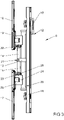
- figure 3 shows an enlarged perspective view of the forend lever mechanism 8 in a position that locks a connecting rod fitting 5 .
- the housing frame 18 encloses the drive lever 12 in the closed position. In this position, the drive lever 12 is only accessible with a gripping element 28 provided for gripping.
- the two links 14, 15 are pivotally mounted on a bearing block 19, 20 and on the central link 13 via bearings 21-23.
- the bearing blocks 19, 20 are mounted on the connecting rod sections 16, 17, the axes of rotation 24, 25 of the bearing blocks 19, 20 on the connecting rod sections 16, 17 and on the links 14, 15 being arranged perpendicular to one another.
- the bearings 22, 23 of the links 14, 15 on the bearing blocks 19, 20 are in line with the bearing 21 of the links 14, 15 on the central link 13, so that the links 14, 15 are arranged in a row in the locking position are. That's it Forend lever mechanism 8 designed to be self-locking and the connecting rod sections 16, 17 cannot be moved without the central link 13 being driven.
- the central link 13 is driven by the drive lever 12 being pivoted about a bearing 26 in the housing frame 18 and taking the central link 13 with it.
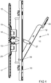
- figure 4 shows the forend lever mechanism 8 figure 3 in the unlocked position.
- the drive lever 12 is opposite the off position figure 3 deflected and pulls the links 14, 15 via the central link 13 in the direction of the housing frame 18.
- the coupling of the drive lever 12 to the central link 13 takes place via a bearing 27.
- the bearing blocks 19, 20 and thus the connecting rod sections 16, 17 are pulled together until they collide.
- the unlocking position of the forend lever mechanism 8 is fixed.
- the drive lever 12, like the links 14, 15 and the central link 13, is made of flat steel.
- the material thickness of the drive lever 12 corresponds to twice the material thickness of the individual links 14, 15.
- a central link 13 is arranged on both sides of the drive lever 12 and the two links 14, 15 in each case
Landscapes
- Engineering & Computer Science (AREA)
- Mechanical Engineering (AREA)
- Lock And Its Accessories (AREA)
- Hinges (AREA)
Abstract
Description
- Die Erfindung betrifft ein Stulphebelgetriebe zur wahlweisen Verriegelung oder Entriegelung eines unterschlagenen Flügels von zweiflügeligen Fenstern, Fenstertüren oder dergleichen mit zwei an einem feststehenden Bauteil längsverschieblich und gegensinnig zueinander geführten Treibstangenabschnitten, mit einem schwenkbar gelagerten Antriebshebel und mit einem Lenker zur Verbindung der Treibstangenabschnitte mit dem Antriebshebel. Weiterhin betrifft die Erfindung ein zweiflügeliges Fenster, Fenstertür oder dergleichen mit einem Stulphebelgetriebe.
- Ein solches Stulphebelgetriebe ist beispielsweise aus der
DE 10 2009 005 342 B4 bekannt. Bei diesem Stulphebelgetriebe ist der Antriebshebel an einem der Treibstangenabschnitte gelagert und über einen Lenker an dem anderen Treibstangenabschnitt angelenkt. Durch das Verschwenken des Antriebshebels wird der Abstand der Treibstangenabschnitte zueinander verkleinert oder vergrößert. Eine Lagerung des Antriebshebels an dem einen der Treibstangenabschnitte hat eine Längsführung in einem feststehenden Bauteil. Hierdurch können auch beide Treibstangenabschnitte bei der gleichen Stellung des Antriebshebels in die gleiche Richtung verschoben werden. Hierdurch gestaltet sich die Bedienung des Stulphebelgetriebes besonders unkomfortabel. Eine positionsgenaue Ansteuerung von Verschlüssen über die Treibstangenabschnitte ist hierdurch zudem nur schwer möglich. - Aus der
EP 3 708 743 A1 ist ein Stulphebelgetriebe bekannt geworden, bei dem der Antriebshebel schwenkbar auf einem Stulpschienenabschnitt gelagert ist und über einen Lenker eine einzige Treibstange antreibt. Da der Stulpschienenabschnitt jedoch meist eine Beschlagnut der Treibstange abdeckt, führt die Lagerung des Antriebshebels auf dem Stulpschienenabschnitt zu sehr großen Abmessungen. Daher werden solche Stulphebelgetriebe nicht in der gleichen Höhe angeordnet, wie ein Antriebsgetriebe am anderen Flügel. - Der Erfindung liegt das Problem zugrunde, ein Stulphebelgetriebe der eingangs genannten Art so weiterzubilden, dass es besonders komfortabel zu bedienen ist und besonders kompakt aufgebaut ist. Weiterhin soll ein besonders komfortabel zu bedienendes und kompakt aufgebautes zweiflügeliges Fenster, Fenstertür oder dergleichen mit einem solchen Stulphebelgetriebe geschaffen werden.
- Das erstgenannte Problem wird erfindungsgemäß dadurch gelöst, dass der Antriebshebel an dem feststehenden Bauteil schwenkbar gelagert ist und dass die Treibstangenabschnitte jeweils über einen Lenker mit dem Antriebshebel verbunden sind.
- Durch diese Gestaltung lässt sich der Antriebshebel über eine sehr kompakte Lagerung mit dem feststehenden Bauteil verbinden. Ausladende Führungen oder dergleichen sind dank der Erfindung nicht erforderlich. Hierdurch gestaltet sich die Lagerung des Antriebshebels besonders kompakt. Durch die beiden Lenker sind die Positionen der beiden Treibstangenabschnitte in Abhängigkeit von dem Schwenkwinkel des Antriebshebels zudem zueinander genau festgelegt. Die Bedienung des Stulphebelgetriebes gestaltet sich hierdurch besonders komfortabel.
- Die Kraftübertragung von dem Antriebshebel auf die beiden Lenker könnte beispielsweise durch eine direkte Lagerung der Lenker auf dem Antriebshebel erfolgen. Hierdurch ist jedoch einer der Lenker näher an der Lagerung des Antriebshebels an dem feststehenden Bauteil angeordnet als der andere Lenker. Dies führt zu einem ungleichmäßigen Antrieb der Treibstangenabschnitte. Ein weitgehend gleichmäßiges Antreiben beider Treibstangenabschnitte lässt sich jedoch gemäß einer vorteilhaften Weiterbildung der Erfindung einfach erreichen, wenn zwischen dem Antriebshebel und den beiden Lenkern ein Zentrallenker angeordnet ist. Durch diese Gestaltung wird der Antrieb der beiden Treibstangenabschnitte durch ein dreiteiliges Lenkersystem gebildet.
- Zur weiteren Vergleichmäßigung des Antriebs der Treibstangenabschnitte trägt es gemäß einer anderen vorteilhaften Weiterbildung der Erfindung bei, wenn der Abstand einer Lagerung des Antriebshebels am feststehenden Bauteil von einer Lagerung des Zentrallenkers größer ist als die Länge des Zentrallenkers.
- Ein unberechtigtes Entriegeln des Stulphebelgetriebes durch eine versuchte Manipulation an den Treibstangenabschnitten lässt sich gemäß einer anderen vorteilhaften Weiterbildung der Erfindung einfach vermeiden, wenn die beiden Lenker in geschlossener Stellung des Stulphebelgetriebes in einer Reihe angeordnet sind. Durch diese Gestaltung ist das Stulphebelgetriebe selbsthemmend gestaltet.
- Eine unkomfortable Reibung beim Antrieb des Stulphebelgetriebes lässt sich gemäß einer anderen vorteilhaften Weiterbildung der Erfindung besonders gering halten, wenn die Länge der Lenker größer ist als die Länge des Zentrallenkers. Die hierdurch besonders lang gestalteten Lenker ermöglichen eine nahezu gerade Krafteinleitung in Bewegungsrichtung der Treibstangenabschnitte. Weiterhin kann hierdurch der Zentrallenker besonders kurz gestaltet sein, wodurch das Stulphebelgetriebe besonders geringe Abmessungen aufweist.
- Kippmomente beim Verschwenken des Antriebshebels lassen sich gemäß einer anderen vorteilhaften Weiterbildung der Erfindung besonders gering halten, wenn zwei Zentrallenker parallel zueinander angeordnet sind und wenn der Antriebshebel und die beiden Lenker zwischen den parallelen Zentrallenkern angeordnet sind.
- Das Stulphebelgetriebe ist gemäß einer anderen vorteilhaften Weiterbildung der Erfindung besonders kompakt und weist zudem eine hohe Stabilität auf, wenn der Antriebshebel und die Treibstangenabschnitte aus Flachmaterial gefertigt sind und wenn die Ebenen des Antriebshebels quer zu den Ebenen der Treibstangenabschnitte ausgerichtet sind.
- Toleranzen zwischen dem feststehenden Bauteil und den Treibstangenabschnitten lassen sich gemäß einer anderen vorteilhaften Weiterbildung der Erfindung einfach ausgleichen, wenn die Lenker schwenkbar an Lagerböcken gelagert sind und wenn die Lagerböcke drehbar auf den Treibstangenabschnitten gelagert sind, wobei deren Drehachsen senkrecht zueinander angeordnet sind.
- Zur weiteren Verringerung der Abmessungen des Stulphebelgetriebes trägt es gemäß einer anderen vorteilhaften Weiterbildung der Erfindung bei, wenn das feststehende Bauteil als den Antriebshebel in verriegelnder Stellung umschließender Gehäuserahmen ausgebildet ist und wenn der Gehäuserahmen bündig mit einer die Treibstangenabschnitte führenden Beschlagnut abschließt.
- Bei bekannten zweiflügeligen Fenstern, Fenstertüren oder dergleichen sind die Stulphebelgetriebe meist an einer besonders tiefen Stelle des Flügels angeordnet und damit unkomfortabel zu betätigen. Das zweitgenannte Problem, nämlich die Schaffung eines besonders komfortabel zu bedienenden und kompakt aufgebauten zweiflügeligen Fensters, Fenstertür oder dergleichen wird erfindungsgemäß dadurch gelöst, dass das Stulphebelgetriebe und ein Antriebsgetriebe des anderen Flügels auf der gleichen Höhe angeordnet sind. Durch diese Gestaltung sind beide für die Verriegelung der Flügel erforderlichen Getriebe auf der gleichen Höhe angeordnet, wodurch deren Betätigung besonders komfortabel ist. Die Voraussetzung für die Anordnung der beiden Getriebe ist die besonders kompakte Gestaltung des Stulphebelgetriebes.
- Die Erfindung lässt zahlreiche Ausführungsformen zu. Zur weiteren Verdeutlichung ihres Grundprinzips ist eine davon in der Zeichnung dargestellt und wird nachfolgend beschrieben. Diese zeigt in
- Fig.1
- ein zweiflügeliges Fenster mit zwei Treibstangenantrieben,
- Fig.2
- vergrößert ein Antriebsgetriebe und ein Stulphebelgetriebe der Treibstangenantriebe aus
Figur 1 , - Fig.3
- stark vergrößert das Stulphebelgetriebe aus
Figur 2 in einer perspektivischen verriegelnden Darstellung, - Fig.4
- stark vergrößert das Stulphebelgetriebe aus
Figur 2 in einer perspektivischen entriegelnden Darstellung. -
Figur 1 zeigt ein zweiflügeliges Fenster ohne Mittelpfosten mit zwei an einem Rahmen 1 über vertikale Achsen angelenkten Flügeln 2, 3. Die Flügel 2, 3 haben jeweils einen Treibstangenbeschlag 4, 5 mit nicht näher dargestellten Verschlüssen, über den sie mit dem Rahmen 1 verriegelt werden. Einer der Treibstangenbeschläge 4 lässt sich über ein Antriebsgetriebe 6 mittels einer Handhabe 7 antreiben. Der andere der Treibstangenbeschläge 5 hat ein verdeckt in einer zwischen den Flügeln 2, 3 befindlichen Falzluft angeordnetes Stulphebelgetriebe 8. -
Figur 2 zeigt das Antriebsgetriebe 6 und das Stulphebelgetriebe 8 in einer vergrößerten Darstellung mit angrenzenden Bereichen der Flügel 2, 3. Flügelüberschläge zur gegenseitigen Überlappung der Flügel 2, 3 sind zur Vereinfachung der Zeichnung nicht dargestellt. Hierbei ist zu erkennen, dass das Antriebsgetriebe 6 und das Stulphebelgetriebe 8 auf der gleichen Höhe angeordnet sind. Das Antriebsgetriebe 6 treibt über ein mit der Handhabe 7 ausFigur 1 verbundenes Ritzel 9 zwei Treibstangenabschnitte 10, 11 gleichsinnig an. Das Stulphebelgetriebe 8 treibt über einen mit einem Antriebshebel 12 verbundenen Zentrallenker 13 und zwei Lenker 14, 15 zwei Treibstangenabschnitte 16, 17 gegensinnig an. Der Antriebshebel 12 liegt in einem bündig mit dem einen Flügel 3 abschließenden Gehäuserahmen 18 und ist nach dem Öffnen des mit dem Antriebsgetriebe 6 verriegelbaren Flügels 2 zugänglich. Der Gehäuserahmen 18 ist fest mit dem einen Flügel 3 verbunden. Weiterhin schließt der Gehäuserahmen 18 eine nicht dargestellte Beschlagnut des Flügels 3 ab. -
Figur 3 zeigt vergrößert das Stulphebelgetriebe 8 in einer den einen Treibstangenbeschlag 5 verriegelnden Stellung in perspektivischer Darstellung. Der Gehäuserahmen 18 umschließt den Antriebshebel 12 in geschlossener Stellung. Der Antriebshebel 12 ist in dieser Stellung ausschließlich mit einem zum Greifen vorgesehenen Griffelement 28 zugänglich. Die beiden Lenker 14, 15 sind an einem Lagerbock 19, 20 und an dem Zentrallenker 13 über Lagerungen 21 - 23 schwenkbar gelagert. Die Lagerböcke 19, 20 sind an den Treibstangenabschnitten 16, 17 gelagert, wobei die Drehachsen 24, 25 der Lagerböcke 19, 20 an den Treibstangenabschnitten 16, 17 und an den Lenkern 14, 15 senkrecht zueinander angeordnet sind. Die Lagerungen 22, 23 der Lenker 14, 15 an den Lagerböcken 19, 20 befinden sich in einer Linie mit der Lagerung 21 der Lenker 14, 15 an dem Zentrallenker 13, so dass die Lenker 14, 15 in der verriegelnden Stellung in einer Reihe angeordnet sind. Damit ist das Stulphebelgetriebe 8 selbsthemmend gestaltet und die Treibstangenabschnitte 16, 17 können nicht ohne Antrieb des Zentrallenkers 13 bewegt werden. Der Antrieb des Zentrallenkers 13 erfolgt, indem der Antriebshebel 12 um eine Lagerung 26 im Gehäuserahmen 18 verschwenkt wird und dabei den Zentrallenker 13 mitnimmt. -
Figur 4 zeigt das Stulphebelgetriebe 8 ausFigur 3 in der entriegelnden Stellung. Der Antriebshebel 12 ist gegenüber der Stellung ausFigur 3 ausgelenkt und zieht die Lenker 14, 15 über den Zentrallenker 13 in Richtung des Gehäuserahmens 18. Die Koppelung des Antriebshebels 12 mit dem Zentrallenker 13 erfolgt über eine Lagerung 27. Dabei werden die Lagerböcke 19, 20 und damit die Treibstangenabschnitte 16, 17 zusammengezogen, bis sie aneinanderstoßen. Hierdurch ist die entriegelnde Position des Stulphebelgetriebes 8 festgelegt. Der Antriebshebel 12 ist wie die Lenker 14, 15 und der Zentrallenker 13 aus Flachstahl gefertigt. Die Materialstärke des Antriebshebels 12 entspricht der der doppelten Materialstärke der einzelnen Lenker 14, 15. Auf beiden Seiten des Antriebshebels 12 und der beiden Lenker 14, 15 ist jeweils ein Zentrallenker 13 angeordnet
Claims (10)
- Stulphebelgetriebe (8) zur wahlweisen Verriegelung oder Entriegelung eines unterschlagenen Flügels (3) von zweiflügeligen Fenstern, Fenstertüren oder dergleichen mit zwei an einem feststehenden Bauteil längsverschieblich und gegensinnig zueinander geführten Treibstangenabschnitten (16, 17), mit einem schwenkbar gelagerten Antriebshebel (12) und mit einem Lenker (14, 15) zur Verbindung der Treibstangenabschnitte (16, 17) mit dem Antriebshebel (12), dadurch gekennzeichnet, dass der Antriebshebel (12) an dem feststehenden Bauteil schwenkbar gelagert ist und dass die Treibstangenabschnitte (16, 17) jeweils über einen Lenker (14, 15) mit dem Antriebshebel (12) verbunden sind.
- Stulphebelgetriebe nach Anspruch 1, dadurch gekennzeichnet, dass zwischen dem Antriebshebel (12) und den beiden Lenkern (14, 15) ein Zentrallenker (13) angeordnet ist.
- Stulphebelgetriebe nach Anspruch 1 oder 2, dadurch gekennzeichnet, dass der Abstand einer Lagerung (26) des Antriebshebels (12) am feststehenden Bauteil von einer Lagerung (27) des Zentrallenkers (13) größer ist als die Länge des Zentrallenkers (13).
- Stulphebelgetriebe nach Anspruch 2 oder 3, dadurch gekennzeichnet, dass die Länge der Lenker (14, 15) größer ist als die Länge des Zentrallenkers (13).
- Stulphebelgetriebe nach zumindest einem der vorhergehenden Ansprüche, dadurch gekennzeichnet, dass die beiden Lenker (14, 15) in geschlossener Stellung des Stulphebelgetriebes (8) in einer Reihe angeordnet sind.
- Stulphebelgetriebe nach zumindest einem der Ansprüche 2 bis 5, dadurch gekennzeichnet, dass zwei Zentrallenker (13) parallel zueinander angeordnet sind und dass der Antriebshebel (12) und die beiden Lenker (14, 15) zwischen den parallelen Zentrallenkern (13) angeordnet sind.
- Stulphebelgetriebe nach zumindest einem der vorhergehenden Ansprüche, dadurch gekennzeichnet, dass der Antriebshebel (12) und die Treibstangenabschnitte (16, 17) aus Flachmaterial gefertigt sind und dass die Ebenen des Antriebshebels (12) quer zu den Ebenen der Treibstangenabschnitte (16, 17) ausgerichtet sind.
- Stulphebelgetriebe nach zumindest einem der vorhergehenden Ansprüche, dadurch gekennzeichnet, dass die Lenker (14, 15) schwenkbar an Lagerböcken (19, 20) gelagert sind und dass die Lagerböcke (19, 20) drehbar auf den Treibstangenabschnitten (16, 17) gelagert sind, wobei deren Drehachsen (24, 25) senkrecht zueinander angeordnet sind.
- Stulphebelgetriebe nach zumindest einem der vorhergehenden Ansprüche, dadurch gekennzeichnet, dass das feststehende Bauteil als den Antriebshebel (12) in verriegelnder Stellung umschließender Gehäuserahmen (18) ausgebildet ist und dass der Gehäuserahmen (18) bündig mit einer die Treibstangenabschnitte (16, 17) führenden Beschlagnut abschließt.
- Zweiflügeliges Fenster, Fenstertür oder dergleichen mit einem Stulphebelgetriebe nach zumindest einem der vorhergehenden Ansprüche, dadurch gekennzeichnet, dass das Stulphebelgetriebe (8) und ein Antriebsgetriebe (6) des anderen Flügels (2) auf der gleichen Höhe angeordnet sind.
Applications Claiming Priority (1)
| Application Number | Priority Date | Filing Date | Title |
|---|---|---|---|
| DE102021205345.9A DE102021205345A1 (de) | 2021-05-26 | 2021-05-26 | Stulphebelgetriebe zur wahlweisen Verriegelung oder Entriegelung eines unterschlagenen Flügels von zweiflügeligen Fenstern und zweiflügeliges Fenster, Fenstertür oder dergleichen mit einem Stulphebelgetriebe |
Publications (2)
| Publication Number | Publication Date |
|---|---|
| EP4095339A1 true EP4095339A1 (de) | 2022-11-30 |
| EP4095339B1 EP4095339B1 (de) | 2024-01-31 |
Family
ID=81749391
Family Applications (1)
| Application Number | Title | Priority Date | Filing Date |
|---|---|---|---|
| EP22174230.7A Active EP4095339B1 (de) | 2021-05-26 | 2022-05-19 | Stulphebelgetriebe |
Country Status (3)
| Country | Link |
|---|---|
| EP (1) | EP4095339B1 (de) |
| DE (1) | DE102021205345A1 (de) |
| ES (1) | ES2975665T3 (de) |
Cited By (1)
| Publication number | Priority date | Publication date | Assignee | Title |
|---|---|---|---|---|
| US20230003053A1 (en) * | 2017-06-01 | 2023-01-05 | Interlock Usa, Inc. | Lever action automatic shootbolt operator with magnetically-triggered locking mechanism |
Citations (7)
| Publication number | Priority date | Publication date | Assignee | Title |
|---|---|---|---|---|
| FR1059193A (fr) * | 1952-06-17 | 1954-03-23 | Manuf Forezienne De Quincaille | Crémone pour portes et fenêtres du type lardé dans l'épaisseur du battant |
| FR1310327A (fr) * | 1962-01-12 | 1962-11-23 | Quincaillerie Daffi De | Crémone |
| FR1544855A (fr) * | 1967-09-28 | 1968-11-08 | Massard Jean Ets | Mécanisme de commande de crémone |
| DE19825417A1 (de) * | 1998-06-06 | 1999-12-09 | Roto Frank Ag | Verriegelungsbeschlag mit Hebelgetriebe im schließseitigen Falz eines von zwei schwenkbaren Flügeln eines mehrflügeligen Fensters, einer mehrflügeligen Tür oder dergleichen |
| DE102009005342B4 (de) | 2009-01-16 | 2012-10-18 | Roto Frank Ag | Verschlussvorrichtung für den Standflügel eines zweiflügeligen Fensters |
| EP3708743A1 (de) | 2019-03-13 | 2020-09-16 | Aug. Winkhaus GmbH & Co. KG | Stulphebelgetriebe zur wahlweisen verriegelung oder entriegelung eines unterschlagenen flügels von zweiflügeligen fenstern |
| US20200291697A1 (en) * | 2017-11-22 | 2020-09-17 | Rittal Gmbh & Co. Kg | Closing device for an electrical enclosure, and a corresponding electrical enclosure |
-
2021
- 2021-05-26 DE DE102021205345.9A patent/DE102021205345A1/de not_active Withdrawn
-
2022
- 2022-05-19 ES ES22174230T patent/ES2975665T3/es active Active
- 2022-05-19 EP EP22174230.7A patent/EP4095339B1/de active Active
Patent Citations (7)
| Publication number | Priority date | Publication date | Assignee | Title |
|---|---|---|---|---|
| FR1059193A (fr) * | 1952-06-17 | 1954-03-23 | Manuf Forezienne De Quincaille | Crémone pour portes et fenêtres du type lardé dans l'épaisseur du battant |
| FR1310327A (fr) * | 1962-01-12 | 1962-11-23 | Quincaillerie Daffi De | Crémone |
| FR1544855A (fr) * | 1967-09-28 | 1968-11-08 | Massard Jean Ets | Mécanisme de commande de crémone |
| DE19825417A1 (de) * | 1998-06-06 | 1999-12-09 | Roto Frank Ag | Verriegelungsbeschlag mit Hebelgetriebe im schließseitigen Falz eines von zwei schwenkbaren Flügeln eines mehrflügeligen Fensters, einer mehrflügeligen Tür oder dergleichen |
| DE102009005342B4 (de) | 2009-01-16 | 2012-10-18 | Roto Frank Ag | Verschlussvorrichtung für den Standflügel eines zweiflügeligen Fensters |
| US20200291697A1 (en) * | 2017-11-22 | 2020-09-17 | Rittal Gmbh & Co. Kg | Closing device for an electrical enclosure, and a corresponding electrical enclosure |
| EP3708743A1 (de) | 2019-03-13 | 2020-09-16 | Aug. Winkhaus GmbH & Co. KG | Stulphebelgetriebe zur wahlweisen verriegelung oder entriegelung eines unterschlagenen flügels von zweiflügeligen fenstern |
Cited By (2)
| Publication number | Priority date | Publication date | Assignee | Title |
|---|---|---|---|---|
| US20230003053A1 (en) * | 2017-06-01 | 2023-01-05 | Interlock Usa, Inc. | Lever action automatic shootbolt operator with magnetically-triggered locking mechanism |
| US11959307B2 (en) * | 2017-06-01 | 2024-04-16 | Interlock Usa, Inc. | Lever action automatic shootbolt operator with magnetically-triggered locking mechanism |
Also Published As
| Publication number | Publication date |
|---|---|
| DE102021205345A1 (de) | 2022-12-01 |
| ES2975665T3 (es) | 2024-07-11 |
| EP4095339B1 (de) | 2024-01-31 |
Similar Documents
| Publication | Publication Date | Title |
|---|---|---|
| EP0492341B1 (de) | Verschlussgetriebe für ein zweiflügeliges Fenster, od. dgl. | |
| DE4321099A1 (de) | Belüftungseinrichtung für Fenster oder Türen | |
| EP4095339B1 (de) | Stulphebelgetriebe | |
| DE19652599C2 (de) | Ent- und Verriegelung für eine einen Standflügel und einen Gangflügel aufweisende Tür | |
| EP1867819B1 (de) | Verschluss für einen Treibstangenbeschlag und Treibstangenbeschlag mit einem solchen Verschluss | |
| DE8711496U1 (de) | Verschluß für zweiflügelige Fenster, Türen od. dgl. | |
| EP4336006A1 (de) | Beschlag für einen gegen einen rahmen schwenkbaren flügel | |
| EP4116529B1 (de) | Verriegelungseinheit | |
| EP0667435A1 (de) | Zusatzverriegelungsvorrichtung für ein Fenster, eine Tür o.dgl. mit wenigstens einem drehbarem Flügel | |
| EP1288418B1 (de) | Beschlagseinheit für ein Kipp- oder Drehkippfenster | |
| EP3371397B1 (de) | Beschlaganordnung | |
| DE10038867B4 (de) | Türanlage mit Verriegelungsvorrichtung | |
| EP4146888B1 (de) | Scharnierbaugruppe mit gemeinsamer betätigung | |
| DE19745553A1 (de) | Schließvorrichtung | |
| EP0845566A2 (de) | Flügeleinheit | |
| DE8816638U1 (de) | Verriegelungsgetriebe für Flügel von Fenstern, Türen o.dgl. | |
| EP0844356B1 (de) | Vorrichtung zur Betätigung eines Fensters | |
| EP1393420A1 (de) | Schaltschrank für eine elektrische schaltanlage mit einer tür | |
| EP1533454B1 (de) | Treibstangenbeschlag | |
| EP4174266A1 (de) | Flügelanordnung | |
| DE3715044A1 (de) | Stangenschloss fuer tueren od. dgl. | |
| EP3744929A1 (de) | Stangenverschluss | |
| DE19603415C1 (de) | Vorrichtung zur Verriegelung eines zwischen zwei Endstellungen um eine Achse schwenkbaren, in Verschlußstellung befindlichen Bauteils zum Verschließen einer Zugangsöffnung zu einem von Wänden umschlossenen Raum | |
| EP4230828A1 (de) | Treibstangenbeschlag mit mehreren verschlüssen | |
| EP4041974B1 (de) | Ausstellvorrichtung für einen dreh-kipp-flügel eines fensters oder einer tür |
Legal Events
| Date | Code | Title | Description |
|---|---|---|---|
| PUAI | Public reference made under article 153(3) epc to a published international application that has entered the european phase |
Free format text: ORIGINAL CODE: 0009012 |
|
| STAA | Information on the status of an ep patent application or granted ep patent |
Free format text: STATUS: THE APPLICATION HAS BEEN PUBLISHED |
|
| AK | Designated contracting states |
Kind code of ref document: A1 Designated state(s): AL AT BE BG CH CY CZ DE DK EE ES FI FR GB GR HR HU IE IS IT LI LT LU LV MC MK MT NL NO PL PT RO RS SE SI SK SM TR |
|
| P01 | Opt-out of the competence of the unified patent court (upc) registered |
Effective date: 20230516 |
|
| STAA | Information on the status of an ep patent application or granted ep patent |
Free format text: STATUS: REQUEST FOR EXAMINATION WAS MADE |
|
| 17P | Request for examination filed |
Effective date: 20230627 |
|
| RBV | Designated contracting states (corrected) |
Designated state(s): AL AT BE BG CH CY CZ DE DK EE ES FI FR GB GR HR HU IE IS IT LI LT LU LV MC MK MT NL NO PL PT RO RS SE SI SK SM TR |
|
| GRAP | Despatch of communication of intention to grant a patent |
Free format text: ORIGINAL CODE: EPIDOSNIGR1 |
|
| STAA | Information on the status of an ep patent application or granted ep patent |
Free format text: STATUS: GRANT OF PATENT IS INTENDED |
|
| INTG | Intention to grant announced |
Effective date: 20230921 |
|
| GRAS | Grant fee paid |
Free format text: ORIGINAL CODE: EPIDOSNIGR3 |
|
| GRAA | (expected) grant |
Free format text: ORIGINAL CODE: 0009210 |
|
| STAA | Information on the status of an ep patent application or granted ep patent |
Free format text: STATUS: THE PATENT HAS BEEN GRANTED |
|
| AK | Designated contracting states |
Kind code of ref document: B1 Designated state(s): AL AT BE BG CH CY CZ DE DK EE ES FI FR GB GR HR HU IE IS IT LI LT LU LV MC MK MT NL NO PL PT RO RS SE SI SK SM TR |
|
| REG | Reference to a national code |
Ref country code: GB Ref legal event code: FG4D Free format text: NOT ENGLISH Ref country code: CH Ref legal event code: EP |
|
| REG | Reference to a national code |
Ref country code: DE Ref legal event code: R096 Ref document number: 502022000454 Country of ref document: DE |
|
| REG | Reference to a national code |
Ref country code: IE Ref legal event code: FG4D Free format text: LANGUAGE OF EP DOCUMENT: GERMAN |
|
| REG | Reference to a national code |
Ref country code: LT Ref legal event code: MG9D |
|
| REG | Reference to a national code |
Ref country code: NL Ref legal event code: MP Effective date: 20240131 |
|
| PG25 | Lapsed in a contracting state [announced via postgrant information from national office to epo] |
Ref country code: IS Free format text: LAPSE BECAUSE OF FAILURE TO SUBMIT A TRANSLATION OF THE DESCRIPTION OR TO PAY THE FEE WITHIN THE PRESCRIBED TIME-LIMIT Effective date: 20240531 |
|
| PG25 | Lapsed in a contracting state [announced via postgrant information from national office to epo] |
Ref country code: LT Free format text: LAPSE BECAUSE OF FAILURE TO SUBMIT A TRANSLATION OF THE DESCRIPTION OR TO PAY THE FEE WITHIN THE PRESCRIBED TIME-LIMIT Effective date: 20240131 |
|
| REG | Reference to a national code |
Ref country code: ES Ref legal event code: FG2A Ref document number: 2975665 Country of ref document: ES Kind code of ref document: T3 Effective date: 20240711 |
|
| PG25 | Lapsed in a contracting state [announced via postgrant information from national office to epo] |
Ref country code: GR Free format text: LAPSE BECAUSE OF FAILURE TO SUBMIT A TRANSLATION OF THE DESCRIPTION OR TO PAY THE FEE WITHIN THE PRESCRIBED TIME-LIMIT Effective date: 20240501 |
|
| PG25 | Lapsed in a contracting state [announced via postgrant information from national office to epo] |
Ref country code: NL Free format text: LAPSE BECAUSE OF FAILURE TO SUBMIT A TRANSLATION OF THE DESCRIPTION OR TO PAY THE FEE WITHIN THE PRESCRIBED TIME-LIMIT Effective date: 20240131 Ref country code: RS Free format text: LAPSE BECAUSE OF FAILURE TO SUBMIT A TRANSLATION OF THE DESCRIPTION OR TO PAY THE FEE WITHIN THE PRESCRIBED TIME-LIMIT Effective date: 20240430 Ref country code: HR Free format text: LAPSE BECAUSE OF FAILURE TO SUBMIT A TRANSLATION OF THE DESCRIPTION OR TO PAY THE FEE WITHIN THE PRESCRIBED TIME-LIMIT Effective date: 20240131 |
|
| PG25 | Lapsed in a contracting state [announced via postgrant information from national office to epo] |
Ref country code: RS Free format text: LAPSE BECAUSE OF FAILURE TO SUBMIT A TRANSLATION OF THE DESCRIPTION OR TO PAY THE FEE WITHIN THE PRESCRIBED TIME-LIMIT Effective date: 20240430 Ref country code: NO Free format text: LAPSE BECAUSE OF FAILURE TO SUBMIT A TRANSLATION OF THE DESCRIPTION OR TO PAY THE FEE WITHIN THE PRESCRIBED TIME-LIMIT Effective date: 20240430 Ref country code: NL Free format text: LAPSE BECAUSE OF FAILURE TO SUBMIT A TRANSLATION OF THE DESCRIPTION OR TO PAY THE FEE WITHIN THE PRESCRIBED TIME-LIMIT Effective date: 20240131 Ref country code: LT Free format text: LAPSE BECAUSE OF FAILURE TO SUBMIT A TRANSLATION OF THE DESCRIPTION OR TO PAY THE FEE WITHIN THE PRESCRIBED TIME-LIMIT Effective date: 20240131 Ref country code: IS Free format text: LAPSE BECAUSE OF FAILURE TO SUBMIT A TRANSLATION OF THE DESCRIPTION OR TO PAY THE FEE WITHIN THE PRESCRIBED TIME-LIMIT Effective date: 20240531 Ref country code: HR Free format text: LAPSE BECAUSE OF FAILURE TO SUBMIT A TRANSLATION OF THE DESCRIPTION OR TO PAY THE FEE WITHIN THE PRESCRIBED TIME-LIMIT Effective date: 20240131 Ref country code: GR Free format text: LAPSE BECAUSE OF FAILURE TO SUBMIT A TRANSLATION OF THE DESCRIPTION OR TO PAY THE FEE WITHIN THE PRESCRIBED TIME-LIMIT Effective date: 20240501 Ref country code: FI Free format text: LAPSE BECAUSE OF FAILURE TO SUBMIT A TRANSLATION OF THE DESCRIPTION OR TO PAY THE FEE WITHIN THE PRESCRIBED TIME-LIMIT Effective date: 20240131 Ref country code: BG Free format text: LAPSE BECAUSE OF FAILURE TO SUBMIT A TRANSLATION OF THE DESCRIPTION OR TO PAY THE FEE WITHIN THE PRESCRIBED TIME-LIMIT Effective date: 20240131 |
|
| PG25 | Lapsed in a contracting state [announced via postgrant information from national office to epo] |
Ref country code: PL Free format text: LAPSE BECAUSE OF FAILURE TO SUBMIT A TRANSLATION OF THE DESCRIPTION OR TO PAY THE FEE WITHIN THE PRESCRIBED TIME-LIMIT Effective date: 20240131 Ref country code: PT Free format text: LAPSE BECAUSE OF FAILURE TO SUBMIT A TRANSLATION OF THE DESCRIPTION OR TO PAY THE FEE WITHIN THE PRESCRIBED TIME-LIMIT Effective date: 20240531 |
|
| PG25 | Lapsed in a contracting state [announced via postgrant information from national office to epo] |
Ref country code: SE Free format text: LAPSE BECAUSE OF FAILURE TO SUBMIT A TRANSLATION OF THE DESCRIPTION OR TO PAY THE FEE WITHIN THE PRESCRIBED TIME-LIMIT Effective date: 20240131 Ref country code: PT Free format text: LAPSE BECAUSE OF FAILURE TO SUBMIT A TRANSLATION OF THE DESCRIPTION OR TO PAY THE FEE WITHIN THE PRESCRIBED TIME-LIMIT Effective date: 20240531 Ref country code: PL Free format text: LAPSE BECAUSE OF FAILURE TO SUBMIT A TRANSLATION OF THE DESCRIPTION OR TO PAY THE FEE WITHIN THE PRESCRIBED TIME-LIMIT Effective date: 20240131 Ref country code: LV Free format text: LAPSE BECAUSE OF FAILURE TO SUBMIT A TRANSLATION OF THE DESCRIPTION OR TO PAY THE FEE WITHIN THE PRESCRIBED TIME-LIMIT Effective date: 20240131 |
|
| PG25 | Lapsed in a contracting state [announced via postgrant information from national office to epo] |
Ref country code: DK Free format text: LAPSE BECAUSE OF FAILURE TO SUBMIT A TRANSLATION OF THE DESCRIPTION OR TO PAY THE FEE WITHIN THE PRESCRIBED TIME-LIMIT Effective date: 20240131 |
|
| PG25 | Lapsed in a contracting state [announced via postgrant information from national office to epo] |
Ref country code: SM Free format text: LAPSE BECAUSE OF FAILURE TO SUBMIT A TRANSLATION OF THE DESCRIPTION OR TO PAY THE FEE WITHIN THE PRESCRIBED TIME-LIMIT Effective date: 20240131 |
|
| PG25 | Lapsed in a contracting state [announced via postgrant information from national office to epo] |
Ref country code: EE Free format text: LAPSE BECAUSE OF FAILURE TO SUBMIT A TRANSLATION OF THE DESCRIPTION OR TO PAY THE FEE WITHIN THE PRESCRIBED TIME-LIMIT Effective date: 20240131 Ref country code: CZ Free format text: LAPSE BECAUSE OF FAILURE TO SUBMIT A TRANSLATION OF THE DESCRIPTION OR TO PAY THE FEE WITHIN THE PRESCRIBED TIME-LIMIT Effective date: 20240131 |
|
| PG25 | Lapsed in a contracting state [announced via postgrant information from national office to epo] |
Ref country code: SK Free format text: LAPSE BECAUSE OF FAILURE TO SUBMIT A TRANSLATION OF THE DESCRIPTION OR TO PAY THE FEE WITHIN THE PRESCRIBED TIME-LIMIT Effective date: 20240131 |
|
| PG25 | Lapsed in a contracting state [announced via postgrant information from national office to epo] |
Ref country code: SM Free format text: LAPSE BECAUSE OF FAILURE TO SUBMIT A TRANSLATION OF THE DESCRIPTION OR TO PAY THE FEE WITHIN THE PRESCRIBED TIME-LIMIT Effective date: 20240131 Ref country code: SK Free format text: LAPSE BECAUSE OF FAILURE TO SUBMIT A TRANSLATION OF THE DESCRIPTION OR TO PAY THE FEE WITHIN THE PRESCRIBED TIME-LIMIT Effective date: 20240131 Ref country code: RO Free format text: LAPSE BECAUSE OF FAILURE TO SUBMIT A TRANSLATION OF THE DESCRIPTION OR TO PAY THE FEE WITHIN THE PRESCRIBED TIME-LIMIT Effective date: 20240131 Ref country code: EE Free format text: LAPSE BECAUSE OF FAILURE TO SUBMIT A TRANSLATION OF THE DESCRIPTION OR TO PAY THE FEE WITHIN THE PRESCRIBED TIME-LIMIT Effective date: 20240131 Ref country code: DK Free format text: LAPSE BECAUSE OF FAILURE TO SUBMIT A TRANSLATION OF THE DESCRIPTION OR TO PAY THE FEE WITHIN THE PRESCRIBED TIME-LIMIT Effective date: 20240131 Ref country code: CZ Free format text: LAPSE BECAUSE OF FAILURE TO SUBMIT A TRANSLATION OF THE DESCRIPTION OR TO PAY THE FEE WITHIN THE PRESCRIBED TIME-LIMIT Effective date: 20240131 |
|
| REG | Reference to a national code |
Ref country code: DE Ref legal event code: R097 Ref document number: 502022000454 Country of ref document: DE |
|
| REG | Reference to a national code |
Ref country code: DE Ref legal event code: R081 Ref document number: 502022000454 Country of ref document: DE Owner name: AUG. WINKHAUS SE & CO. KG, DE Free format text: FORMER OWNER: AUG. WINKHAUS GMBH & CO. KG, 48291 TELGTE, DE |
|
| PLBE | No opposition filed within time limit |
Free format text: ORIGINAL CODE: 0009261 |
|
| STAA | Information on the status of an ep patent application or granted ep patent |
Free format text: STATUS: NO OPPOSITION FILED WITHIN TIME LIMIT |
|
| 26N | No opposition filed |
Effective date: 20241101 |
|
| PG25 | Lapsed in a contracting state [announced via postgrant information from national office to epo] |
Ref country code: MC Free format text: LAPSE BECAUSE OF FAILURE TO SUBMIT A TRANSLATION OF THE DESCRIPTION OR TO PAY THE FEE WITHIN THE PRESCRIBED TIME-LIMIT Effective date: 20240131 |
|
| PG25 | Lapsed in a contracting state [announced via postgrant information from national office to epo] |
Ref country code: LU Free format text: LAPSE BECAUSE OF NON-PAYMENT OF DUE FEES Effective date: 20240519 |
|
| PG25 | Lapsed in a contracting state [announced via postgrant information from national office to epo] |
Ref country code: MC Free format text: LAPSE BECAUSE OF FAILURE TO SUBMIT A TRANSLATION OF THE DESCRIPTION OR TO PAY THE FEE WITHIN THE PRESCRIBED TIME-LIMIT Effective date: 20240131 Ref country code: LU Free format text: LAPSE BECAUSE OF NON-PAYMENT OF DUE FEES Effective date: 20240519 |
|
| PG25 | Lapsed in a contracting state [announced via postgrant information from national office to epo] |
Ref country code: IE Free format text: LAPSE BECAUSE OF NON-PAYMENT OF DUE FEES Effective date: 20240519 |
|
| PG25 | Lapsed in a contracting state [announced via postgrant information from national office to epo] |
Ref country code: SI Free format text: LAPSE BECAUSE OF FAILURE TO SUBMIT A TRANSLATION OF THE DESCRIPTION OR TO PAY THE FEE WITHIN THE PRESCRIBED TIME-LIMIT Effective date: 20240131 |
|
| PG25 | Lapsed in a contracting state [announced via postgrant information from national office to epo] |
Ref country code: FR Free format text: LAPSE BECAUSE OF NON-PAYMENT OF DUE FEES Effective date: 20240531 |
|
| PG25 | Lapsed in a contracting state [announced via postgrant information from national office to epo] |
Ref country code: CY Free format text: LAPSE BECAUSE OF FAILURE TO SUBMIT A TRANSLATION OF THE DESCRIPTION OR TO PAY THE FEE WITHIN THE PRESCRIBED TIME-LIMIT; INVALID AB INITIO Effective date: 20220519 |
|
| PG25 | Lapsed in a contracting state [announced via postgrant information from national office to epo] |
Ref country code: HU Free format text: LAPSE BECAUSE OF FAILURE TO SUBMIT A TRANSLATION OF THE DESCRIPTION OR TO PAY THE FEE WITHIN THE PRESCRIBED TIME-LIMIT; INVALID AB INITIO Effective date: 20220519 |
|
| REG | Reference to a national code |
Ref country code: CH Ref legal event code: H13 Free format text: ST27 STATUS EVENT CODE: U-0-0-H10-H13 (AS PROVIDED BY THE NATIONAL OFFICE) Effective date: 20251223 |
|
| PG25 | Lapsed in a contracting state [announced via postgrant information from national office to epo] |
Ref country code: CH Free format text: LAPSE BECAUSE OF NON-PAYMENT OF DUE FEES Effective date: 20250531 |
|
| PG25 | Lapsed in a contracting state [announced via postgrant information from national office to epo] |
Ref country code: TR Free format text: LAPSE BECAUSE OF FAILURE TO SUBMIT A TRANSLATION OF THE DESCRIPTION OR TO PAY THE FEE WITHIN THE PRESCRIBED TIME-LIMIT Effective date: 20240131 |
|
| PG25 | Lapsed in a contracting state [announced via postgrant information from national office to epo] |
Ref country code: CH Free format text: THE PATENT HAS BEEN ANNULLED BY A DECISION OF A NATIONAL AUTHORITY Effective date: 20250531 |
|
| PGFP | Annual fee paid to national office [announced via postgrant information from national office to epo] |
Ref country code: ES Payment date: 20260618 Year of fee payment: 5 |
|
| PGFP | Annual fee paid to national office [announced via postgrant information from national office to epo] |
Ref country code: IT Payment date: 20260529 Year of fee payment: 5 |
|
| PGFP | Annual fee paid to national office [announced via postgrant information from national office to epo] |
Ref country code: DE Payment date: 20260520 Year of fee payment: 5 |
|
| PGFP | Annual fee paid to national office [announced via postgrant information from national office to epo] |
Ref country code: AT Payment date: 20260714 Year of fee payment: 5 |
|
| PGFP | Annual fee paid to national office [announced via postgrant information from national office to epo] |
Ref country code: BE Payment date: 20260521 Year of fee payment: 5 |