EP4095312B1 - Etikett zur bereitstellung von informationen einer schiene - Google Patents
Etikett zur bereitstellung von informationen einer schiene Download PDFInfo
- Publication number
- EP4095312B1 EP4095312B1 EP21176103.6A EP21176103A EP4095312B1 EP 4095312 B1 EP4095312 B1 EP 4095312B1 EP 21176103 A EP21176103 A EP 21176103A EP 4095312 B1 EP4095312 B1 EP 4095312B1
- Authority
- EP
- European Patent Office
- Prior art keywords
- tag
- rail
- base body
- lip
- label
- Prior art date
- Legal status (The legal status is an assumption and is not a legal conclusion. Google has not performed a legal analysis and makes no representation as to the accuracy of the status listed.)
- Active
Links
Images


Classifications
-
- G—PHYSICS
- G09—EDUCATION; CRYPTOGRAPHY; DISPLAY; ADVERTISING; SEALS
- G09F—DISPLAYING; ADVERTISING; SIGNS; LABELS OR NAME-PLATES; SEALS
- G09F3/00—Labels, tag tickets, or similar identification or indication means; Seals; Postage or like stamps
- G09F3/08—Fastening or securing by means not forming part of the material of the label itself
- G09F3/10—Fastening or securing by means not forming part of the material of the label itself by an adhesive layer
-
- E—FIXED CONSTRUCTIONS
- E01—CONSTRUCTION OF ROADS, RAILWAYS, OR BRIDGES
- E01B—PERMANENT WAY; PERMANENT-WAY TOOLS; MACHINES FOR MAKING RAILWAYS OF ALL KINDS
- E01B26/00—Tracks or track components not covered by any one of the preceding groups
-
- G—PHYSICS
- G09—EDUCATION; CRYPTOGRAPHY; DISPLAY; ADVERTISING; SEALS
- G09F—DISPLAYING; ADVERTISING; SIGNS; LABELS OR NAME-PLATES; SEALS
- G09F3/00—Labels, tag tickets, or similar identification or indication means; Seals; Postage or like stamps
- G09F3/02—Forms or constructions
- G09F3/0297—Forms or constructions including a machine-readable marking, e.g. a bar code
-
- G—PHYSICS
- G09—EDUCATION; CRYPTOGRAPHY; DISPLAY; ADVERTISING; SEALS
- G09F—DISPLAYING; ADVERTISING; SIGNS; LABELS OR NAME-PLATES; SEALS
- G09F3/00—Labels, tag tickets, or similar identification or indication means; Seals; Postage or like stamps
- G09F3/02—Forms or constructions
- G09F2003/0202—Forms or constructions printed before use
Definitions
- the present invention relates to a tag for providing the information of a rail and/or a weld joint of a rail.
- aluminothermic welding was invented to weld rail tracks with the development of the metallurgical and chemical industries.
- a worker should understand the characteristics of a rail.
- a worker should also understand the characteristics and the history of the weld joint. Therefore, the information of a rail or a weld joint of a rail becomes crucial for workers to prepare the welding or future repair and maintenance of a rail. Namely, before/during/after welding, workers need to obtain information of the rail or of the weld joint of the rail.
- a conventional rail clamp does not provide a fast-marking, non-destructive and stable-fastening tag for providing the information of a rail.
- the objective of the present invention is to provide a fast-marking, non-destructive and stable-fastening tag for providing the information of a rail.
- a first aspect of the present invention provides a tag for providing the information of a rail, the rail comprising a rail head, a rail web and a rail foot, the tag configured to be attached to the rail foot in the transverse direction of the rail, comprising: a base body which partially encloses the rail foot, and a label which contains information of the rail.
- the base body includes an upper lip and a lower lip, the label located on the upper side of the upper lip.
- a fastener that attaches the base body to the rail, the fastener located on the upper side of the lower lip.
- the fastener is made of magnet or adhesive material including adhesive glues, an adhesive tape, or an adhesive strip.
- the base body includes another upper lip, the lower lip extending along the bottom of the rail foot and integrally connecting the two upper lips, the two upper lips respectively holding the two sides of the rail foot.
- the upper lip includes an engaging tip for holding the tag onto the rail foot.
- the base body includes a groove on the upper side of the lower tip and the engaging tip includes a slope feature.
- the label is designed as an adhesive sticker or as an imprint which is made by printing, laser engraving or cutting, or as electronic data identification, the label including a two-dimensional code (e.g., QR code or data matrix).
- a two-dimensional code e.g., QR code or data matrix
- the base body is made of rubber, plastic, metal, wood, or polymer composite.
- the information includes the used process and material, date of execution, ingredient, quality, characteristic, function, feature, purpose, history, or use of the rail or of a weld joint of the rail.
- the present invention aims to provide a fast-marking, non-destructive and stable-fastening tag for providing the information of a rail.
- Fig. 1 is a perspective view of a tag for providing the information of a rail in accordance with the first embodiment of the present invention.
- Fig. 2 is a perspective view of a tag of Fig. 1 which is to be applied to a rail.
- Fig. 3 is a perspective view of a tag of Fig. 1 which is applied to a rail.
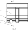
- Fig. 4 is a side view of Fig. 3 .
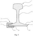
- Fig. 5 is a cross-section view taken along the line A-A of Fig. 4 .
- Fig. 6 is a perspective view of a tag for providing the information of a rail in accordance with the second embodiment of the present invention.
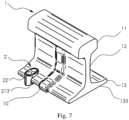
- Fig. 7 is a perspective view of a tag of Fig. 6 which is applied to a rail.
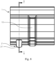
- Fig. 8 is a side view of Fig. 7 .
- Fig. 9 is a cross-section view taken along the line B-B of Fig. 8 .
- Fig. 10 is an illustrated view
- a rail 1 comprises a rail head 11, a rail web 12, and a rail foot 13.
- the rail 1 can also include a weld joint 10, such as an aluminothermic welding joint.
- the present invention can be applied to all types and all lengths of rails.
- the rail 1 shown in the drawings is illustrated just as a simplified section of rails for the purpose of the explanation.
- the first embodiment and the second embodiment provide a tag 2, 2' for providing the information of a rail 1.
- the tag 2, 2' is configured to be attached to the rail foot 13 in the transverse direction T of the rail 1. For example, after the repair of a specific section of a rail 1, a rail worker can efficiently apply the tag 2, 2' to the rail foot 13 of a rail 1.
- the worker can simply check the information shown on the tag 2, 2' that is attached to the specific section of the rail 1. Namely, if a worker wants to obtain the information of the rail 1, a worker does not need to inspect or test the rail 1 itself again.
- the information includes the used process and material, date of execution, ingredient, quality, characteristic, function, feature, purpose, history, or use of the rail 1 or of a weld joint 10 of the rail 1.
- the tag 2, 2' comprises a base body 21, 21' and a label 22, 22'.
- the base body 21, 21' partially encloses the rail foot 13, holding onto the top 132 of the rail foot 13 and the bottom 133 of the rail foot 13 so that the tag 2, 2' is stably attached to the rail 1.
- the base body 21, 21' is made of rubber, plastic, metal, wood, or polymer composite.
- the base body 21, 21' includes an upper lip 211, 211' and a lower lip 213, 213'.
- the label 22, 22' is located on the upper side 2111, 2111' of the upper lip 211,211'.
- a label 22, 22' contains information of the rail 1.
- the label 22, 22' is mounted on upper side 2111, 2111' of the upper lip 211, 211'.
- the upper lip 211, 211' is disposed horizontally or at an angle to allow the label 22, 22' to be read.
- the label 22, 22' is designed as an adhesive sticker or as an imprint which is made by printing, laser engraving or cutting, the label 22, 22' including a two-dimensional code (e.g., QR code or data matrix), a mark, a trademark, a logo, or a company name.
- the upper side 2111, 2111' of the upper lip 211, 211' includes a grooved platform for receiving the label 22, 22'.
- the upper side 2111, 2111' of the upper lip 211, 211' is a flatten plane.
- the present invention can be categorized into two main embodiments in respect of the attachment to the rail foot 13.
- the tag 2 of the first embodiment further comprises a fastener 23.
- the fastener 23 is made of magnet or adhesive material.
- the magnet can attach to the rail 1 in a non-destructive and efficient manner.
- the adhesive material can be adhesive glues, an adhesive tape, or an adhesive strip.
- the adhesive tape or the adhesive strip can be two sided so that they can stick to the base body 21 and the rail foot 13.
- the fastener 23 is located on the upper side 2131 of the lower lip 213 and attaches the base body 21 to the rail 1 in a substantially non-detachable manner. Particularly, the fastener 23 is used for attaching the tag 2 to the bottom 133 of the rail foot 13. In this way, the fastener 23 achieves a stable attachment between the tag 2 and the rail 1. In a preferred embodiment, the tag 2 attaches only to the bottom 133 of the rail foot 13 by the fastener 23.
- the base body 21' includes another upper lip 211'.
- the two upper lips 211', 212' respectively holding the two sides of the rail foot 13.
- the lower lip 213' extends along the bottom 133 of the rail foot 13 and integrally connecting the two upper lips 211', 212'.
- the base body 21' of the second embodiment may be made of flexible materials, such as rubber, plastics, fibres, metal materials, wood, or polymer composite.
- the label 22' is disposed on one of the two upper lips 211', 212' on either side of the rail 1.
- the label 22' can be provided on both the two upper lips 211', 212'.
- a fastener including magnet or adhesive materials can also be provided on the lower lip 213' of the second embodiment, increasing the stabilization of the tag 2'.
- the upper lip 211' includes an engaging tip 2113' for holding the tag 2' onto the rail foot 13.
- the base body 21' includes a groove 215' on the upper side of the lower tip so that a worker can easily install the tag 2' onto the rail foot 13 without hugely bending the tag 2'.
- the engaging tip 2113' includes a slope feature, which also realizes the easier installation of the tag 2' onto the rail foot 13.
- a slope feature which also realizes the easier installation of the tag 2' onto the rail foot 13.
- a worker can first take advantage of the groove 215' to apply the tag 2' partially to one side of the rail foot 13; and then can sightly rotate the tag 2' in relative to the groove 215' in the direction R and take advantage of the slope feature of the engaging tip 2113' so that the upper tip 212' slides onto the top 132 of the rail foot 13 from the bottom 133 of the rail foot 13. In this way, the tag 2' can firmly attach to the rail foot 13.
- the underside 2112, 2112' of the upper lip 211, 211' is configured to be compatible with the profile of the rail foot 13, preferably an inclining shape of the underside 2112, 2112' of the upper lip 211, 211' which also helps the attachment of the tag 2, 2' and the rail foot 13, whereby the maximum static friction applied by the fastener 23 may prevent subsequent removal of the tag 2, 2' from the rail 1.
- the upper side 2132, 2132' of the lower lip 213, 213' includes a reinforcing protrusion 2133, 2133'.
- the back 214, 214' of the base body 21, 21' is rounded to make unintentional removal of the tag 2, 2' from the rail 1 more difficult.
- the present invention creates a non-destructive and firm connection between the tag 2, 2' and the rail 1.
Landscapes
- Engineering & Computer Science (AREA)
- Physics & Mathematics (AREA)
- General Physics & Mathematics (AREA)
- Theoretical Computer Science (AREA)
- Architecture (AREA)
- Civil Engineering (AREA)
- Structural Engineering (AREA)
- Accommodation For Nursing Or Treatment Tables (AREA)
- Machines For Laying And Maintaining Railways (AREA)
- Devices For Checking Fares Or Tickets At Control Points (AREA)
- Credit Cards Or The Like (AREA)
Claims (25)
- Kennzeichnung zum Bereitstellen von Informationen einer Schiene, wobei die Schiene (1) einen Schienenkopf (11), einen Schienensteg (12) und einen Schienenfuß (13) umfasst, wobei die Kennzeichnung (2, 2') so konfiguriert ist, dass sie am Schienenfuß (13) in der Querrichtung (T) der Schiene (1) befestigt werden kann, wobei die Kennzeichnung (2, 2') Folgendes umfasst:einen Grundkörper (21, 21'), der den Schienenfuß (13) teilweise umschließt, undein Etikett (22, 22'), das Informationen der Schiene (1) enthält,wobei der Grundkörper (21, 21') eine Oberlippe (211, 211') und eine Unterlippe (213, 213') beinhaltet und das Etikett (22, 22') auf der Oberseite (2111, 2111') der Oberlippe (211, 211') angeordnet ist,wobei die Kennzeichnung ferner einen Verschluss (23) umfasst, der den Grundkörper (21) an der Schiene (1) befestigt, dadurch gekennzeichnet, dass der Verschluss (23) aus Klebematerial gebildet ist und an der Oberseite (2131) der Unterlippe (213) angeordnet ist.
- Kennzeichnung nach Anspruch 1, wobei das Klebematerial Klebstoffe, ein Klebeband oder einen Klebestreifen beinhaltet.
- Kennzeichnung nach Anspruch 1 oder 2, wobei der Verschluss (23) zum Befestigen der Kennzeichnung (2) an der Unterseite (133) des Schienenfußes (13) verwendet wird.
- Kennzeichnung nach Anspruch 1, wobei der Grundkörper (21') eine andere Oberlippe (212') beinhaltet, wobei sich die Unterlippe (213') entlang der Unterseite (133) des Schienenfußes (13) erstreckt und die zwei Oberlippen (211', 212') einstückig verbindet, wobei die zwei Oberlippen (211', 212') jeweils die zwei Seiten des Schienenfußes (13) festhalten.
- Kennzeichnung nach Anspruch 4, wobei die Oberlippe (212') eine Eingriffsspitze (2113') zum Festhalten der Kennzeichnung (2') auf dem Schienenfuß (13) beinhaltet.
- Kennzeichnung nach Anspruch 5, wobei der Grundkörper (21') eine Rille (215') auf der Oberseite der unteren Spitze beinhaltet und die Eingriffsspitze (2113') ein Neigungsmerkmal beinhaltet.
- Kennzeichnung nach einem der Ansprüche 1-6, wobei die Unterseite (2112, 2112') der Oberlippe (211, 211') so konfiguriert ist, dass sie mit dem Profil des Schienenfußes (13) kompatibel ist.
- Kennzeichnung nach einem der Ansprüche 1-7, wobei die Unterseite (2132, 2132') der Unterlippe (213, 213') einen verstärkenden Vorsprung (2133, 2133') beinhaltet.
- Kennzeichnung nach einem der Ansprüche 1-8, wobei das Etikett (22, 22') als Aufkleber oder als Aufdruck konzipiert ist, das durch Bedrucken, Lasergravieren oder Schneiden oder als elektronische Datenidentifikation gebildet ist, wobei das Etikett einen zweidimensionalen Code (z. B. QR-Code oder Data-Matrix) beinhaltet.
- Kennzeichnung nach einem der Ansprüche 1-9, wobei die Oberlippe (211, 211') horizontal oder angewinkelt angeordnet ist, um das Lesen des Etiketts (22, 22') zu ermöglichen.
- Kennzeichnung nach einem der Ansprüche 1-10, wobei die Schiene (1) eine Schweißverbindung (10) beinhaltet.
- Kennzeichnung nach einem der Ansprüche 1-11, wobei der Grundkörper (21, 21') aus Gummi, Kunststoff, Metall, Holz oder einem Polymerverbundstoff gebildet ist.
- Kennzeichnung nach einem der Ansprüche 1-12, wobei die Informationen den verwendeten Prozess und das Material, das Datum der Ausführung, den Bestandteil, die Qualität, die Eigenschaft, die Funktion, das Merkmal, den Zweck, die Geschichte oder die Verwendung der Schiene oder einer Schweißverbindung der Schiene beinhalten.
- Kennzeichnung zum Bereitstellen von Informationen einer Schiene, wobei die Schiene (1) einen Schienenkopf (11), einen Schienensteg (12) und einen Schienenfuß (13) umfasst, wobei die Kennzeichnung (2, 2') so konfiguriert ist, dass sie am Schienenfuß (13) in der Querrichtung (T) der Schiene (1) befestigt werden kann, wobei die Kennzeichnung (2, 2') Folgendes umfasst:einen Grundkörper (21, 21'), der den Schienenfuß (13) teilweise umschließt, undein Etikett (22, 22'), das Informationen der Schiene (1) enthält,wobei der Grundkörper (21, 21') eine Oberlippe (211, 211') und eine Unterlippe (213, 213') beinhaltet und das Etikett (22, 22') auf der Oberseite (2111, 2111') der Oberlippe (211, 211') angeordnet ist,wobei die Kennzeichnung ferner einen Verschluss (23) umfasst, der den Grundkörper (21) an der Schiene (1) befestigt, dadurch gekennzeichnet, dass der Verschluss (23) aus einem Magnet gebildet ist und an der Oberseite (2131) der Unterlippe (213) angeordnet ist.
- Kennzeichnung nach Anspruch 14, wobei der Verschluss (23) zum Befestigen der Kennzeichnung (2) an der Unterseite (133) des Schienenfußes (13) verwendet wird.
- Kennzeichnung nach Anspruch 14, wobei der Grundkörper (21') eine andere Oberlippe (212') beinhaltet, wobei sich die Unterlippe (213') entlang der Unterseite (133) des Schienenfußes (13) erstreckt und die zwei Oberlippen (211', 212') einstückig verbindet, wobei die zwei Oberlippen (211', 212') jeweils die zwei Seiten des Schienenfußes (13) festhalten.
- Kennzeichnung nach Anspruch 16, wobei die Oberlippe (212') eine Eingriffsspitze (2113') zum Festhalten der Kennzeichnung (2') auf dem Schienenfuß (13) beinhaltet.
- Kennzeichnung nach Anspruch 17, wobei der Grundkörper (21') eine Rille (215') auf der Oberseite der unteren Spitze beinhaltet und die Eingriffsspitze (2113') ein Neigungsmerkmal beinhaltet.
- Kennzeichnung nach einem der Ansprüche 14-18, wobei die Unterseite (2112, 2112') der Oberlippe (211, 211') so konfiguriert ist, dass sie mit dem Profil des Schienenfußes (13) kompatibel ist.
- Kennzeichnung nach einem der Ansprüche 14-19, wobei die Unterseite (2132, 2132') der Unterlippe (213, 213') einen verstärkenden Vorsprung (2133, 2133') beinhaltet.
- Kennzeichnung nach einem der Ansprüche 14-20, wobei das Etikett als Aufkleber oder als Aufdruck konzipiert ist, das durch Bedrucken, Lasergravieren oder Schneiden oder als elektronische Datenidentifikation gebildet ist, wobei das Etikett einen zweidimensionalen Code (z. B. QR-Code oder Data-Matrix) beinhaltet.
- Kennzeichnung nach einem der Ansprüche 14-21, wobei die Oberlippe (211, 211') horizontal oder angewinkelt angeordnet ist, um das Lesen des Etiketts (22, 22') zu ermöglichen.
- Kennzeichnung nach einem der Ansprüche 14-22, wobei die Schiene (1) eine Schweißverbindung (10) beinhaltet.
- Kennzeichnung nach einem der Ansprüche 14-23, wobei der Grundkörper (21, 21') aus Gummi, Kunststoff, Metall, Holz oder einem Polymerverbundstoff gebildet ist.
- Kennzeichnung nach einem der Ansprüche 14-24, wobei die Informationen den verwendeten Prozess und das Material, das Datum der Ausführung, den Bestandteil, die Qualität, die Eigenschaft, die Funktion, das Merkmal, den Zweck, die Geschichte oder die Verwendung der Schiene oder einer Schweißverbindung der Schiene beinhalten.
Priority Applications (5)
| Application Number | Priority Date | Filing Date | Title |
|---|---|---|---|
| EP21176103.6A EP4095312B1 (de) | 2021-05-27 | 2021-05-27 | Etikett zur bereitstellung von informationen einer schiene |
| AU2022283501A AU2022283501A1 (en) | 2021-05-27 | 2022-05-12 | Tag for providing the information of a rail |
| CN202280037230.8A CN117441048A (zh) | 2021-05-27 | 2022-05-12 | 提供铁路信息的标签 |
| PCT/EP2022/062916 WO2022248239A1 (en) | 2021-05-27 | 2022-05-12 | Tag for providing the information of a rail |
| US18/289,980 US20240265832A1 (en) | 2021-05-27 | 2022-05-12 | Tag for providing the information of a rail |
Applications Claiming Priority (1)
| Application Number | Priority Date | Filing Date | Title |
|---|---|---|---|
| EP21176103.6A EP4095312B1 (de) | 2021-05-27 | 2021-05-27 | Etikett zur bereitstellung von informationen einer schiene |
Publications (3)
| Publication Number | Publication Date |
|---|---|
| EP4095312A1 EP4095312A1 (de) | 2022-11-30 |
| EP4095312B1 true EP4095312B1 (de) | 2024-09-18 |
| EP4095312C0 EP4095312C0 (de) | 2024-09-18 |
Family
ID=76522746
Family Applications (1)
| Application Number | Title | Priority Date | Filing Date |
|---|---|---|---|
| EP21176103.6A Active EP4095312B1 (de) | 2021-05-27 | 2021-05-27 | Etikett zur bereitstellung von informationen einer schiene |
Country Status (5)
| Country | Link |
|---|---|
| US (1) | US20240265832A1 (de) |
| EP (1) | EP4095312B1 (de) |
| CN (1) | CN117441048A (de) |
| AU (1) | AU2022283501A1 (de) |
| WO (1) | WO2022248239A1 (de) |
Families Citing this family (1)
| Publication number | Priority date | Publication date | Assignee | Title |
|---|---|---|---|---|
| EP4575090B1 (de) * | 2023-12-18 | 2026-02-11 | Voestalpine Rail Technology Gmbh | Rillenschiene für die bildung von verkehrswegen für schienenfahrzeuge und verfahren zur identifikation von rillenschienen in einem gleis |
Family Cites Families (10)
| Publication number | Priority date | Publication date | Assignee | Title |
|---|---|---|---|---|
| US1222575A (en) * | 1916-08-08 | 1917-04-10 | C L Crooks | Railroad-stake. |
| US4826078A (en) * | 1987-11-13 | 1989-05-02 | Imo Delaval Inc. | Wire-to-track-base retainer clip and keeper |
| DE19914662A1 (de) * | 1999-03-31 | 2000-10-12 | Thyssen Krupp Materials & Serv | Markierungsplatte |
| JP2001195001A (ja) * | 1999-10-28 | 2001-07-19 | Nippon Hoan Kizai Seizo Kk | 表示板 |
| JP3151921U (ja) * | 2009-04-28 | 2009-07-09 | 有限会社岡田製作所 | 鉄道用標示装置 |
| US9074327B2 (en) * | 2012-08-24 | 2015-07-07 | David L. Reichle | Railroad attachment clamp |
| US9045151B2 (en) * | 2013-06-18 | 2015-06-02 | Tech4U Dynamics Inc. | Track barcode systems for railroad management |
| WO2015124834A1 (en) * | 2014-02-21 | 2015-08-27 | Miika Kavonius | Railmark |
| DK3384482T3 (da) * | 2015-09-18 | 2022-01-10 | Brand Lane Aps | Metoder og enheder til reklame på jernbaneskinner |
| US20210054574A1 (en) * | 2018-12-19 | 2021-02-25 | Randall Graham | Magnetic Railroad Clip |
-
2021
- 2021-05-27 EP EP21176103.6A patent/EP4095312B1/de active Active
-
2022
- 2022-05-12 AU AU2022283501A patent/AU2022283501A1/en active Pending
- 2022-05-12 CN CN202280037230.8A patent/CN117441048A/zh active Pending
- 2022-05-12 WO PCT/EP2022/062916 patent/WO2022248239A1/en not_active Ceased
- 2022-05-12 US US18/289,980 patent/US20240265832A1/en active Pending
Also Published As
| Publication number | Publication date |
|---|---|
| WO2022248239A1 (en) | 2022-12-01 |
| US20240265832A1 (en) | 2024-08-08 |
| AU2022283501A1 (en) | 2023-11-02 |
| CN117441048A (zh) | 2024-01-23 |
| EP4095312C0 (de) | 2024-09-18 |
| EP4095312A1 (de) | 2022-11-30 |
Similar Documents
| Publication | Publication Date | Title |
|---|---|---|
| EP4095312B1 (de) | Etikett zur bereitstellung von informationen einer schiene | |
| KR101782563B1 (ko) | 다층 접착 테이프를 가지는 밸런스 웨이트 | |
| JP3045774U (ja) | 金属線条体巻装用リール | |
| US20020170213A1 (en) | Marking element for marking timber, especially tree trunks | |
| US12008928B2 (en) | Labelling material for marking electrical installations and method for producing a labelling strip | |
| JPS59167921A (ja) | ケ−ブルの標識付与装置 | |
| CN102537001A (zh) | 附接至塑料构件的功能元件及构件组件 | |
| JPH01502416A (ja) | 自己装填バインダ | |
| US20220399690A1 (en) | Method for producing an electrical connection arrangement, and electrical connection arrangement | |
| EP1944631A1 (de) | Halter für eine optische faser | |
| US6520223B1 (en) | Indicia carrying element for marking timber and more particularly logs | |
| US20090175581A1 (en) | Connectored optical fiber sheet and manufacturing method thereof | |
| JP2008246973A (ja) | スタンプマーカー | |
| EP1588609A3 (de) | Verfahren und Satz zum Identifizieren von Tieren | |
| US20100307209A1 (en) | Key ring with tamper-evident closure member, kit for assembling a key ring, and method of using same | |
| JPH11167347A (ja) | 封緘具 | |
| KR20240082073A (ko) | 배터리용 라벨 부착 장치 및 이를 이용하는 방법 | |
| CN214164894U (zh) | 一种定位工装及车辆 | |
| US20240384778A1 (en) | Adhesive based cable tie mount | |
| JPH1123436A (ja) | 引張強度測定用補助治具及び引張強度測定方法 | |
| KR0138392Y1 (ko) | 물류관리 시스템용 자석 부착 바코드 | |
| CN1494755A (zh) | 缆线带 | |
| US20090183400A1 (en) | Name Badge | |
| US20250287493A1 (en) | Heat sink device with defined insertion point, heat sink system, headlamp, vehicle, and method for releasing a printed circuit board glued to a heat sink | |
| US20170253375A1 (en) | Cluster pack comprising labelled containers |
Legal Events
| Date | Code | Title | Description |
|---|---|---|---|
| PUAI | Public reference made under article 153(3) epc to a published international application that has entered the european phase |
Free format text: ORIGINAL CODE: 0009012 |
|
| STAA | Information on the status of an ep patent application or granted ep patent |
Free format text: STATUS: THE APPLICATION HAS BEEN PUBLISHED |
|
| AK | Designated contracting states |
Kind code of ref document: A1 Designated state(s): AL AT BE BG CH CY CZ DE DK EE ES FI FR GB GR HR HU IE IS IT LI LT LU LV MC MK MT NL NO PL PT RO RS SE SI SK SM TR |
|
| STAA | Information on the status of an ep patent application or granted ep patent |
Free format text: STATUS: REQUEST FOR EXAMINATION WAS MADE |
|
| 17P | Request for examination filed |
Effective date: 20221215 |
|
| RBV | Designated contracting states (corrected) |
Designated state(s): AL AT BE BG CH CY CZ DE DK EE ES FI FR GB GR HR HU IE IS IT LI LT LU LV MC MK MT NL NO PL PT RO RS SE SI SK SM TR |
|
| STAA | Information on the status of an ep patent application or granted ep patent |
Free format text: STATUS: EXAMINATION IS IN PROGRESS |
|
| 17Q | First examination report despatched |
Effective date: 20230712 |
|
| GRAP | Despatch of communication of intention to grant a patent |
Free format text: ORIGINAL CODE: EPIDOSNIGR1 |
|
| STAA | Information on the status of an ep patent application or granted ep patent |
Free format text: STATUS: GRANT OF PATENT IS INTENDED |
|
| GRAS | Grant fee paid |
Free format text: ORIGINAL CODE: EPIDOSNIGR3 |
|
| INTG | Intention to grant announced |
Effective date: 20240531 |
|
| GRAA | (expected) grant |
Free format text: ORIGINAL CODE: 0009210 |
|
| STAA | Information on the status of an ep patent application or granted ep patent |
Free format text: STATUS: THE PATENT HAS BEEN GRANTED |
|
| AK | Designated contracting states |
Kind code of ref document: B1 Designated state(s): AL AT BE BG CH CY CZ DE DK EE ES FI FR GB GR HR HU IE IS IT LI LT LU LV MC MK MT NL NO PL PT RO RS SE SI SK SM TR |
|
| REG | Reference to a national code |
Ref country code: GB Ref legal event code: FG4D |
|
| REG | Reference to a national code |
Ref country code: CH Ref legal event code: EP |
|
| REG | Reference to a national code |
Ref country code: DE Ref legal event code: R096 Ref document number: 602021018860 Country of ref document: DE |
|
| REG | Reference to a national code |
Ref country code: IE Ref legal event code: FG4D |
|
| U01 | Request for unitary effect filed |
Effective date: 20240918 |
|
| U07 | Unitary effect registered |
Designated state(s): AT BE BG DE DK EE FI FR IT LT LU LV MT NL PT RO SE SI Effective date: 20240925 |
|
| PG25 | Lapsed in a contracting state [announced via postgrant information from national office to epo] |
Ref country code: NO Free format text: LAPSE BECAUSE OF FAILURE TO SUBMIT A TRANSLATION OF THE DESCRIPTION OR TO PAY THE FEE WITHIN THE PRESCRIBED TIME-LIMIT Effective date: 20241218 |
|
| PG25 | Lapsed in a contracting state [announced via postgrant information from national office to epo] |
Ref country code: GR Free format text: LAPSE BECAUSE OF FAILURE TO SUBMIT A TRANSLATION OF THE DESCRIPTION OR TO PAY THE FEE WITHIN THE PRESCRIBED TIME-LIMIT Effective date: 20241219 |
|
| PG25 | Lapsed in a contracting state [announced via postgrant information from national office to epo] |
Ref country code: HR Free format text: LAPSE BECAUSE OF FAILURE TO SUBMIT A TRANSLATION OF THE DESCRIPTION OR TO PAY THE FEE WITHIN THE PRESCRIBED TIME-LIMIT Effective date: 20240918 |
|
| PG25 | Lapsed in a contracting state [announced via postgrant information from national office to epo] |
Ref country code: RS Free format text: LAPSE BECAUSE OF FAILURE TO SUBMIT A TRANSLATION OF THE DESCRIPTION OR TO PAY THE FEE WITHIN THE PRESCRIBED TIME-LIMIT Effective date: 20241218 |
|
| PG25 | Lapsed in a contracting state [announced via postgrant information from national office to epo] |
Ref country code: RS Free format text: LAPSE BECAUSE OF FAILURE TO SUBMIT A TRANSLATION OF THE DESCRIPTION OR TO PAY THE FEE WITHIN THE PRESCRIBED TIME-LIMIT Effective date: 20241218 Ref country code: NO Free format text: LAPSE BECAUSE OF FAILURE TO SUBMIT A TRANSLATION OF THE DESCRIPTION OR TO PAY THE FEE WITHIN THE PRESCRIBED TIME-LIMIT Effective date: 20241218 Ref country code: HR Free format text: LAPSE BECAUSE OF FAILURE TO SUBMIT A TRANSLATION OF THE DESCRIPTION OR TO PAY THE FEE WITHIN THE PRESCRIBED TIME-LIMIT Effective date: 20240918 Ref country code: GR Free format text: LAPSE BECAUSE OF FAILURE TO SUBMIT A TRANSLATION OF THE DESCRIPTION OR TO PAY THE FEE WITHIN THE PRESCRIBED TIME-LIMIT Effective date: 20241219 |
|
| PG25 | Lapsed in a contracting state [announced via postgrant information from national office to epo] |
Ref country code: IS Free format text: LAPSE BECAUSE OF FAILURE TO SUBMIT A TRANSLATION OF THE DESCRIPTION OR TO PAY THE FEE WITHIN THE PRESCRIBED TIME-LIMIT Effective date: 20250118 |
|
| PG25 | Lapsed in a contracting state [announced via postgrant information from national office to epo] |
Ref country code: SM Free format text: LAPSE BECAUSE OF FAILURE TO SUBMIT A TRANSLATION OF THE DESCRIPTION OR TO PAY THE FEE WITHIN THE PRESCRIBED TIME-LIMIT Effective date: 20240918 |
|
| PG25 | Lapsed in a contracting state [announced via postgrant information from national office to epo] |
Ref country code: ES Free format text: LAPSE BECAUSE OF FAILURE TO SUBMIT A TRANSLATION OF THE DESCRIPTION OR TO PAY THE FEE WITHIN THE PRESCRIBED TIME-LIMIT Effective date: 20240918 |
|
| PG25 | Lapsed in a contracting state [announced via postgrant information from national office to epo] |
Ref country code: PL Free format text: LAPSE BECAUSE OF FAILURE TO SUBMIT A TRANSLATION OF THE DESCRIPTION OR TO PAY THE FEE WITHIN THE PRESCRIBED TIME-LIMIT Effective date: 20240918 Ref country code: CZ Free format text: LAPSE BECAUSE OF FAILURE TO SUBMIT A TRANSLATION OF THE DESCRIPTION OR TO PAY THE FEE WITHIN THE PRESCRIBED TIME-LIMIT Effective date: 20240918 |
|
| PG25 | Lapsed in a contracting state [announced via postgrant information from national office to epo] |
Ref country code: SK Free format text: LAPSE BECAUSE OF FAILURE TO SUBMIT A TRANSLATION OF THE DESCRIPTION OR TO PAY THE FEE WITHIN THE PRESCRIBED TIME-LIMIT Effective date: 20240918 |
|
| U20 | Renewal fee for the european patent with unitary effect paid |
Year of fee payment: 5 Effective date: 20250417 |
|
| PGFP | Annual fee paid to national office [announced via postgrant information from national office to epo] |
Ref country code: GB Payment date: 20250401 Year of fee payment: 5 |
|
| PLBE | No opposition filed within time limit |
Free format text: ORIGINAL CODE: 0009261 |
|
| STAA | Information on the status of an ep patent application or granted ep patent |
Free format text: STATUS: NO OPPOSITION FILED WITHIN TIME LIMIT |
|
| 26N | No opposition filed |
Effective date: 20250619 |
|
| REG | Reference to a national code |
Ref country code: CH Ref legal event code: H13 Free format text: ST27 STATUS EVENT CODE: U-0-0-H10-H13 (AS PROVIDED BY THE NATIONAL OFFICE) Effective date: 20251223 |
|
| PG25 | Lapsed in a contracting state [announced via postgrant information from national office to epo] |
Ref country code: CH Free format text: LAPSE BECAUSE OF NON-PAYMENT OF DUE FEES Effective date: 20250531 |
|
| PG25 | Lapsed in a contracting state [announced via postgrant information from national office to epo] |
Ref country code: MC Free format text: LAPSE BECAUSE OF FAILURE TO SUBMIT A TRANSLATION OF THE DESCRIPTION OR TO PAY THE FEE WITHIN THE PRESCRIBED TIME-LIMIT Effective date: 20240918 |