EP4095309A2 - Wäschereigerät mit wäschereizubehör - Google Patents
Wäschereigerät mit wäschereizubehör Download PDFInfo
- Publication number
- EP4095309A2 EP4095309A2 EP22170986.8A EP22170986A EP4095309A2 EP 4095309 A2 EP4095309 A2 EP 4095309A2 EP 22170986 A EP22170986 A EP 22170986A EP 4095309 A2 EP4095309 A2 EP 4095309A2
- Authority
- EP
- European Patent Office
- Prior art keywords
- accessory
- bar assembly
- cabinet
- air
- lid
- Prior art date
- Legal status (The legal status is an assumption and is not a legal conclusion. Google has not performed a legal analysis and makes no representation as to the accuracy of the status listed.)
- Withdrawn
Links
Images









Classifications
-
- D—TEXTILES; PAPER
- D06—TREATMENT OF TEXTILES OR THE LIKE; LAUNDERING; FLEXIBLE MATERIALS NOT OTHERWISE PROVIDED FOR
- D06F—LAUNDERING, DRYING, IRONING, PRESSING OR FOLDING TEXTILE ARTICLES
- D06F39/00—Details of washing machines not specific to a single type of machines covered by groups D06F9/00 - D06F27/00
-
- D—TEXTILES; PAPER
- D06—TREATMENT OF TEXTILES OR THE LIKE; LAUNDERING; FLEXIBLE MATERIALS NOT OTHERWISE PROVIDED FOR
- D06F—LAUNDERING, DRYING, IRONING, PRESSING OR FOLDING TEXTILE ARTICLES
- D06F58/00—Domestic laundry dryers
- D06F58/20—General details of domestic laundry dryers
- D06F58/203—Laundry conditioning arrangements
-
- D—TEXTILES; PAPER
- D06—TREATMENT OF TEXTILES OR THE LIKE; LAUNDERING; FLEXIBLE MATERIALS NOT OTHERWISE PROVIDED FOR
- D06F—LAUNDERING, DRYING, IRONING, PRESSING OR FOLDING TEXTILE ARTICLES
- D06F58/00—Domestic laundry dryers
- D06F58/20—General details of domestic laundry dryers
-
- D—TEXTILES; PAPER
- D06—TREATMENT OF TEXTILES OR THE LIKE; LAUNDERING; FLEXIBLE MATERIALS NOT OTHERWISE PROVIDED FOR
- D06F—LAUNDERING, DRYING, IRONING, PRESSING OR FOLDING TEXTILE ARTICLES
- D06F25/00—Washing machines with receptacles, e.g. perforated, having a rotary movement, e.g. oscillatory movement, the receptacle serving both for washing and for centrifugally separating water from the laundry and having further drying means, e.g. using hot air
-
- D—TEXTILES; PAPER
- D06—TREATMENT OF TEXTILES OR THE LIKE; LAUNDERING; FLEXIBLE MATERIALS NOT OTHERWISE PROVIDED FOR
- D06F—LAUNDERING, DRYING, IRONING, PRESSING OR FOLDING TEXTILE ARTICLES
- D06F37/00—Details specific to washing machines covered by groups D06F21/00 - D06F25/00
-
- D—TEXTILES; PAPER
- D06—TREATMENT OF TEXTILES OR THE LIKE; LAUNDERING; FLEXIBLE MATERIALS NOT OTHERWISE PROVIDED FOR
- D06F—LAUNDERING, DRYING, IRONING, PRESSING OR FOLDING TEXTILE ARTICLES
- D06F37/00—Details specific to washing machines covered by groups D06F21/00 - D06F25/00
- D06F37/02—Rotary receptacles, e.g. drums
-
- D—TEXTILES; PAPER
- D06—TREATMENT OF TEXTILES OR THE LIKE; LAUNDERING; FLEXIBLE MATERIALS NOT OTHERWISE PROVIDED FOR
- D06F—LAUNDERING, DRYING, IRONING, PRESSING OR FOLDING TEXTILE ARTICLES
- D06F37/00—Details specific to washing machines covered by groups D06F21/00 - D06F25/00
- D06F37/02—Rotary receptacles, e.g. drums
- D06F37/04—Rotary receptacles, e.g. drums adapted for rotation or oscillation about a horizontal or inclined axis
- D06F37/06—Ribs, lifters, or rubbing means forming part of the receptacle
-
- D—TEXTILES; PAPER
- D06—TREATMENT OF TEXTILES OR THE LIKE; LAUNDERING; FLEXIBLE MATERIALS NOT OTHERWISE PROVIDED FOR
- D06F—LAUNDERING, DRYING, IRONING, PRESSING OR FOLDING TEXTILE ARTICLES
- D06F57/00—Supporting means, other than simple clothes-lines, for linen or garments to be dried or aired
-
- D—TEXTILES; PAPER
- D06—TREATMENT OF TEXTILES OR THE LIKE; LAUNDERING; FLEXIBLE MATERIALS NOT OTHERWISE PROVIDED FOR
- D06F—LAUNDERING, DRYING, IRONING, PRESSING OR FOLDING TEXTILE ARTICLES
- D06F58/00—Domestic laundry dryers
- D06F58/02—Domestic laundry dryers having dryer drums rotating about a horizontal axis
-
- D—TEXTILES; PAPER
- D06—TREATMENT OF TEXTILES OR THE LIKE; LAUNDERING; FLEXIBLE MATERIALS NOT OTHERWISE PROVIDED FOR
- D06F—LAUNDERING, DRYING, IRONING, PRESSING OR FOLDING TEXTILE ARTICLES
- D06F58/00—Domestic laundry dryers
- D06F58/10—Drying cabinets or drying chambers having heating or ventilating means
-
- D—TEXTILES; PAPER
- D06—TREATMENT OF TEXTILES OR THE LIKE; LAUNDERING; FLEXIBLE MATERIALS NOT OTHERWISE PROVIDED FOR
- D06F—LAUNDERING, DRYING, IRONING, PRESSING OR FOLDING TEXTILE ARTICLES
- D06F39/00—Details of washing machines not specific to a single type of machines covered by groups D06F9/00 - D06F27/00
- D06F39/12—Casings; Tubs
-
- D—TEXTILES; PAPER
- D06—TREATMENT OF TEXTILES OR THE LIKE; LAUNDERING; FLEXIBLE MATERIALS NOT OTHERWISE PROVIDED FOR
- D06F—LAUNDERING, DRYING, IRONING, PRESSING OR FOLDING TEXTILE ARTICLES
- D06F57/00—Supporting means, other than simple clothes-lines, for linen or garments to be dried or aired
- D06F57/12—Supporting means, other than simple clothes-lines, for linen or garments to be dried or aired specially adapted for attachment to walls, ceilings, stoves, or other structures or objects
Definitions
- the present disclosure generally relates to a laundry appliance, and more specifically, to a laundry appliance having various laundry accessories.
- a laundry appliance includes a cabinet.
- a blower is disposed within the cabinet that delivers accessory air through an accessory airflow path.
- An accessory bar assembly is in fluid communication with the accessory airflow path. The accessory bar assembly is configured to suspend articles therefrom and to provide the accessory air for conditioning the articles.
- a vertical axis laundry machine includes a cabinet having a top panel that defines an access opening.
- a lid is coupled with the top panel and having a lower surface. The lid is operable between a raised position above the access opening and a lowered position that covers the access opening.
- a removable panel is selectively positioned on the top panel and over the access opening to define a processing state.
- a heating element is positioned proximate at least one of the lid and the top panel. The heating element is configured to heat at least one of the lower surface of the lid and an upper surface of the removable panel.
- a vertical axis laundry machine includes a cabinet that includes a base positioned proximate a lower portion of the cabinet.
- a drawer is disposed within the base and operable between a stowed position within the base and a supporting position forward of the base.
- a step is disposed within the drawer. The step is attached to the drawer via a scissor linkage. The step is configured to be operable between a flat position and a step position when the drawer is in the supporting position.
- the present illustrated embodiments reside primarily in combinations of method steps and apparatus components related to a cooking appliance door push button assembly. Accordingly, the apparatus components and method steps have been represented, where appropriate, by conventional symbols in the drawings, showing only those specific details that are pertinent to understanding the embodiments of the present disclosure so as not to obscure the disclosure with details that will be readily apparent to those of ordinary skill in the art having the benefit of the description herein. Further, like numerals in the description and drawings represent like elements.
- the terms “upper,” “lower,” “right,” “left,” “rear,” “front,” “vertical,” “horizontal,” and derivatives thereof shall relate to the disclosure as oriented in FIGS. 1A-13B .
- the term “front” shall refer to the surface of the element closer to an intended viewer, and the term “rear” shall refer to the surface of the element further from the intended viewer.
- the disclosure may assume various alternative orientations, except where expressly specified to the contrary.
- the specific devices and processes illustrated in the attached drawings, and described in the following specification are simply exemplary embodiments of the inventive concepts defined in the appended claims. Hence, specific dimensions and other physical characteristics relating to the embodiments disclosed herein are not to be considered as limiting, unless the claims expressly state otherwise.
- reference numeral 10 generally refers to an accessory bar assembly that is incorporated within a laundry appliance 12, where the accessory bar assembly 10 can be used for supporting and suspending articles 13 in a hanging position.
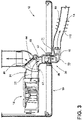
- a blower 14 is disposed within a cabinet 16 of the laundry appliance 12. According to various aspects of the device, the blower 14 delivers accessory air 18 through an accessory airflow path 20 in fluid communication with the accessory bar assembly 10.
- the accessory bar assembly 10 can provide the accessory air 18 for conditioning the articles 13.
- the laundry appliance 12 may be in the form of a dryer, a combination washer and dryer, a washer or other laundry processing appliance. Further, the laundry appliance 12 may be in the form of a vertical axis appliance or a horizontal axis appliance. In some examples, the laundry appliance 12 is in the form of a front-loading dryer.
- the blower 14 delivers process air 22 through a process airflow path 24.
- the process airflow path 24 typically moves the process air 22 from the blower 14, through a primary airflow path that includes a rotating drum 26, then through one or more filtration devices and back to the blower 14 or an outlet 27.
- the process air 22 can be diverted from the outlet 27, or the process airflow path 24, and redirected to the accessory airflow path 20.
- the blower 14 can be an independent blower that provides the accessory air 18 to the accessory bar assembly 10.
- the blower 14 is not typically in fluid communication with the process airflow path 24 and a separate primary blower operates to deliver the process air 22 through the primary airflow path.
- One or more temperature control mechanisms 28 can be incorporated within the process airflow path 24 and/or the accessory airflow path 20 for providing temperature variation within the process air 22 and/or the accessory air 18.
- the temperature control mechanisms 28 can be in the form of various heating and cooling devices.
- one or more humidity, or moisture, control mechanisms can be incorporated within the process airflow path 24 and/or the accessory airflow path 20 for providing water vapor within, and extracting condensate fluid from, the process air 22 and/or the accessory air 18.
- the blower 14 can be configured to provide varying temperatures and humidity of accessory air 18 as needed.
- the accessory bar assembly 10 may include controls to operate at various temperature settings that can include low, medium and high temperature settings and intermediate temperature variations there between.
- the accessory bar assembly 10 may provide water vapor within the accessory air 18 in order to steam the articles 13 and can include low, medium, and high steam control settings.
- the laundry appliance 12 can include a user interface 29, such as a human machine interface (HMI) configured to accept user input regarding various functionalities of the accessory bar assembly 10 (i.e. speed, heat, and moisture controls).
- HMI human machine interface
- humid air can be captured during operation of the appliance, such as during a drying cycle, and delivered to the accessory airflow path 20 for directing steam through the accessory bar assembly 10.
- An accessory port 30 is coupled with the accessory airflow path 20.
- the accessory port 30 and its corresponding mechanisms may be integral with the cabinet 16, which can include being positioned entirely within an interior of the cabinet 16, or positioned such that the accessory port 30 is in fluid communication with an exterior of the cabinet 16.
- the accessory port 30 selectively redirects the process air 22 through the accessory airflow path 20.
- the accessory bar assembly 10 is configured to selectively engage the accessory port 30 to define the accessory airflow path 20. In this manner, when the accessory bar assembly 10 is coupled with the accessory port 30, the accessory air 18 delivered by the blower 14 moves through the accessory port 30 for providing functionality at a particular point, referred to herein as a processing space, using the accessory bar assembly 10.
- the accessory bar assembly 10 can utilize the movement of the accessory air 18 for accomplishing certain tasks within and around the laundry appliance 12, such as drying or otherwise conditioning the articles 13 (i.e. refreshing, de-wrinkling, warming) .
- the accessory bar assembly 10 can produce a drying airflow in the processing space that is typically an area external to the cabinet 16 of the appliance 12.
- the accessory bar assembly 10 utilizes the accessory air 18 in the form of a positive airflow, (i.e., blowing air), but it is within the scope of the disclosure for the accessory bar assembly 10 to utilize negative airflow (i.e., vacuum).
- the accessory bar assembly 10 may include any suitable configuration, including combinations and permutations of configurations disclosed herein.
- the accessory bar assembly 10 may be in the form of a rail 15 ( FIG. 1C ) configured in the form of a hanging-clothes dryer 17. This hanging-clothes dryer 17 can receive a hanger 32 for hanging the articles 13.
- the shape of the rail 15 as will be described further herein can be any one of various extruded shapes, such as a cylinder, a rectangular prism or other similar polygonal prism, arcuate, angled, irregular, and other similar shapes.
- the accessory bar assembly 10 is in the form of a rail 15 including pegs 34 configured as a footwear dryer to receive the articles 13, which may be shoes, boots, slippers and the like.
- the accessory port 30 can include an internal baffle 40 that can be operated to convert the process airflow path 24 from a standard state 42 to an accessory state 44.
- the recirculating dryer operates according to typical operating conditions where clothes, or articles 13, are dried within the rotating drum 26.
- the process air 22 is redirected from the accessory port 30 and through the accessory bar assembly 10 for providing the accessory air 18.
- the baffle 40 can be selectively biased toward the standard state 42, indicative of a standard or conventional operation condition. Insertion of an aspect of the accessory bar assembly 10 operates to overcome this biasing force and move the baffle 40 to an accessory state 44.
- the accessory state 44 is indicative of the accessory port 30 receiving the accessory bar assembly 10 through rotation, extension, insertion or other manipulation of the accessory bar assembly 10 with respect to the accessory port 30.
- the accessory bar assembly 10 is manipulated with respect to the accessory port 30 and the baffle 40 is operated from the standard state 42 to the accessory state 44.
- the process airflow path 24 extends from the blower 14, through the rotating drum 26, past the accessory port 30, which is in the standard state 42, and back to the blower 14.
- various temperature control mechanisms 28 can be disposed within and around the accessory airflow path 20 and the process airflow path 24.
- an interface 46 engages a baffle actuator 48 that biases the baffle 40 to the accessory state 44.
- the baffle 40 can be slidably operable within the accessory port 30 and biased by a biasing mechanism toward the standard state 42. Accordingly, the baffle 40 automatically returns to the standard state 42 when accessory bar assembly 10 is removed from the accessory port 30.
- the baffle actuator 48 can be a linkage that is physically moved by the insertion or other manipulation of the accessory bar assembly 10 with respect to the accessory port 30.
- the baffle actuator 48 can also be a motorized or automatically operated member, such as diverter valve 50.
- the accessory bar assembly 10 is configured to attach to or deploy from accessory port 30 on the cabinet 16.
- the accessory bar assembly 10 is configured to slide in and out of the accessory port 30 to define a storage position 73a and a use position 73b, respectively.
- the accessory bar assembly 10 can be positioned to attach to the cabinet 16 at various locations and positions. Accordingly, the accessory bar assembly 10 can attach to a front portion 19 of the cabinet 16.
- the front portion 19 of the cabinet 16 can include one or more of a front panel 21, a top panel 23, a side panel 25, seams or junctions therebetween, as well as other similar locations relative to the front portion 19 of the cabinet 16.
- the accessory port 30 can be positioned at other locations of the cabinet 16 that are within, or distal from, the front portion 19 of the cabinet 16.
- the accessory state 44 can be indicative of the accessory bar assembly 10 extending from the accessory port 30 in the use position 73b, which is generally shown in FIGS. 1A-11B .
- the motion of the accessory bar assembly 10 to the accessory state 44, as described herein, can be in a linear motion 31, a rotational motion 33 as well as a combination of linear and rotational movements.
- FIGS. 5A and 5B an exemplary accessory bar assembly 10 in the form of a rail 15 is illustrated.
- the accessory bar assembly 10 can slide through a linear motion 31 in and out of the accessory port 30 on the cabinet 16 to define the storage and use positions 73a, 73b, respectively.
- FIGS. 5A and 5B illustrate the accessory bar assembly 10 in various use positions 73b, which may include variable distances that the accessory bar assembly 10 is extended from the accessory port 30 of the cabinet 16.
- the user can pull the accessory bar assembly 10 to extend it from the cabinet 16 to any one of a plurality of use positions 73b.
- a user can manipulate the accessory bar assembly 10 to eject, or extend, the accessory bar assembly 10 from the cabinet 16.
- a push-latch mechanism may be provided to extend the accessory bar assembly 10 upon pushing by the user.
- the accessory bar assembly 10 can include an end portion 56 to facilitate manipulation, by pushing, pulling and rotating, by the user.
- the end portion 56 can be sized larger than a body 58 of the accessory bar assembly 10, which can prevent the articles 13 from sliding off.
- the user can input a control signal that the laundry appliance 12 can process as a use position request. This control signal can result in the laundry appliance 12 controlling the accessory bar assembly 10 to extend, or eject, from the accessory port 30 using a motor or other actuator.
- a user can input a control signal that the laundry appliance 12 can process as a storage position request. This control signal can result in the laundry appliance 12 controlling the motor or actuator of the accessory bar assembly 10 to retract the accessory bar assembly 10 into the accessory port 30.
- the accessory bar assembly 10 can include a plurality of outlets 60 configured to provide the accessory air 18.
- the outlets 60 can be in the form of vents 62, such as a plurality of perforations or micro-perforations of various sizes and configurations, slots, channels, combinations thereof and other openings through which accessory air 18 can be directed.
- the vents 62 are disposed throughout the body 58 of the accessory bar assembly 10 such that the body 58 is covered with the vents 62. Accordingly, articles 13 draped over the accessory bar assembly 10, or suspended therefrom, can be dried with the accessory air 18.
- vents 62 can have a wide range of shapes, sizes and configurations.
- outlets 60 or vents 62 are described, it should be understood that the outlets 60 and the vents 62 are interchangeable and also can be intermingled with one another in any one or more of the various aspects of the device described herein. The presence or absence of the outlets 60 or the vents 62 is not intended to foreclose the use of one or the other.
- FIGS. 6A and 6B another exemplary accessory bar assembly 10 in the form of a rail 15 is illustrated.
- the accessory bar assembly 10 can slide in and out of the accessory port 30 on the cabinet 16 for storage and use positions 73a, 73b, respectively.
- FIGS. 6A and 6B illustrate the accessory bar assembly 10 in use positions 73b, which can include variable lengths extending from the cabinet 16.
- the user can push the accessory bar assembly 10 to eject, or extend, the accessory bar assembly 10 from the cabinet 16, which may include a push-latch mechanism.
- the accessory bar assembly 10 can be pulled to extend it from the cabinet 16.
- various indicia 65 can be included on the surface of the end portion 56 to inform the user as to the presence or status of the accessory bar assembly 10.
- This indicia 65 can be a surface indication as well as an illuminated indicia 65. Changes in the accessory air 18 moving through the accessory bar assembly 10 can also be reflected in this indicia 65.
- the accessory bar assembly 10 can include a plurality of the outlets 60, or vents 62, configured to provide the accessory air 18. As illustrated, the vents 62 are disposed throughout a lower portion 59 of the body 58 of the accessory bar assembly 10 such that the lower portion 59 of the body 58 is covered with the vents 62. In some implementations, an upper portion 61 of the body 58 may not include the vents 62.
- a flow rate of the accessory air 18 is a function of a size, interior dimensions, or interior diameter, of the accessory bar assembly 10 and the corresponding number and size of the outlets 60.
- larger accessory bar assemblies 10 may include a lesser amount of outlets 60, while smaller, or narrower accessory bar assemblies 10 may include a greater amount of outlets 60 and include similar flow rates of the accessory air 18.
- the blower 14 can be configured to operate at a variety of speeds, or levels, to increase or decrease the flow rate of accessory air 18 as needed.
- the accessory bar assembly 10 can include controls to operate at low, medium, and high speed settings, as well as gradual flow rate variations therebetween.
- the flow rate of the accessory air 18 through the outlets 60 or vents 62 can vary depending on how far the accessory bar assembly 10 is extracted from the cabinet. For example, as the accessory bar assembly 10 is extracted from the port 30, more outlets and vents 60, 62 are revealed. The amount of accessory air 18 delivered to the accessory bar assembly 10 can increase to maintain a consistent pressure and velocity of accessory air 18 leaving the outlets and vents 60, 62.
- the accessory port 30 can include an interior sleeve 67 that engages the exterior surface 69 or this interior surface 71 of the accessory bar assembly 10.
- the interior sleeve 67 can close off those outlets 60 and vents 62 that are within the interior sleeve 67.
- greater numbers of the outlets 60 and ports 62 are extracted from the interior sleeve 67 and opened to allow for the movement of accessory air 18 to move therethrough.
- the interior sleeve 67 of the accessory port 30 and the accessory bar assembly 10 cooperate to vary the pressure of accessory air 18 and increase or decrease the air flow through those outlets 60 and ports 62 that are exposed in the particular use position 73b that is being utilized.
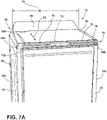
- FIGS. 7A-7C illustrate yet another exemplary accessory bar assembly 10 in the form of a rail 15 that extends in a transverse direction across the front portion 19 of the cabinet 16.
- the accessory bar assembly 10 extends along a width 70 of the cabinet 16 at an upper end 72 thereof.
- the accessory bar assembly 10 is configured to telescope, or slide fore and aft for storage and use positions 73a, 73b, respectively.
- FIG. 7A illustrates the accessory bar assembly 10 in the storage position 73a
- FIGS. 7B and 7C illustrate the accessory bar assembly 10 in the use position 73b, which may include various lengths extending from the cabinet 16.
- the accessory bar assembly 10 may include a generally planar front surface 74 and a back surface 76 configured to be received within a receptacle 78 that forms a receptacle 78 for the accessory bar assembly.
- This receptacle 78 extends transversely along the upper end 72.
- the front surface 74 can also accommodate the surrounding contours of the outer cabinet so that the accessory bar assembly 10 is in a flush configuration within a receptacle 78 of the cabinet.
- the accessory bar assembly 10 can be disposed within the cabinet 16 such that the accessory bar assembly 10 is substantially flush with an outer surface 16a of the cabinet 16.
- the accessory bar assembly 10 can be configured to project from the outer surface 16a of the cabinet 16 such that the accessory bar assembly 10 is not substantially flush with the outer surface 16a.
- the laundry appliance 12 may not include the receptacle 78.
- a transverse body 80 of the accessory bar assembly 10 includes ends 82a, 82b.
- the ends 82a, 82b can be coupled with first and second supports 84, 86, respectively.
- the first and second supports 84, 86 can be slidingly engaged with the cabinet 16 to support the accessory bar assembly 10.
- the first and second supports 84, 86 are disposed along sides 16b, 16c of the cabinet 16, which is illustrated in FIG. 7B .
- the first and second supports 84, 86 are disposed within the cabinet 16, which is illustrated in FIG. 7C .
- the outlets 60, or vents 62 are disposed on the transverse body 80.
- the outlets 60 can be disposed on the front surface 74 and/or the back surface 76 of the accessory bar assembly 10.
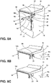
- FIGS. 8A-8C illustrate yet another exemplary accessory bar assembly 10 in the form of a removable bar 91, such as an extension or a wand.
- the accessory bar assembly 10 can include a body 90 having an end 92 configured to selectively couple the accessory port 30.
- FIG. 8A illustrates the accessory bar assembly 10 coupled with the accessory port 30.
- the body 90 may include the outlets 60 in any suitable configuration.
- the accessory bar assembly 10 can be coupled at various positions around the accessory port 30 such that the accessory bar assembly 10 includes a variety of use positions 73b than can define various lengths and angles of operation with respect to the cabinet 16. While illustrated as positioned substantially parallel with a top 16d of the cabinet 16, the accessory bar assembly 10 can be positioned generally perpendicular with the top 16d, or at angles between perpendicular and parallel with the top 16d.
- FIGS. 8B and 8C illustrate the accessory bar assembly 10 removed from the accessory port 30.
- the laundry appliance 12 can include a cover 94, or cap, configured to conceal the accessory port 30 when the accessory bar assembly 10 is not in use.
- the side 16c of the cabinet 16 may include a depression 96 configured to receive the cover 94.
- the accessory bar assembly 10 operates in a similar fashion to that of other aspects of the accessory bar assembly 10, as described herein. It is also contemplated that the accessory bar assembly 10 can be received within a receptacle 78 defined within or otherwise incorporated in the cabinet 16 for the appliance 12.
- the accessory bar assembly 10 can include a body 100 having an end 102 coupled with the accessory port 30.
- the end 102 can be rotatably engaged with the accessory port 30 such that the accessory bar assembly 10 can extend from the cabinet 16 at a variety of positions.
- the end 102 can be fixed in position with respect to the accessory port 30. It is within the scope of the disclosure for the laundry appliance 12 to include more than one accessory port 30.
- the accessory bar assembly 10 can be fixed in position at two ends 102, each of which can be coupled with an accessory port 30.
- the accessory bar assembly 10 can be fixed in position at a single end 102, which can optionally couple a first accessory port 30a or a second accessory port 30b. Therefore, the accessory bar assembly 10 can be reversible, in order to be repositioned into a desired orientation. Further, the outlets 60 can be disposed on any suitable location, including the body 100 of the accessory bar assembly 10. It is contemplated that the accessory bar assembly 10 can be operable in both a linear motion 31 and a rotational motion 33 to manipulate the accessory bar assembly 10 between the storage position 73a and the use position 73b.
- this can be characterized as a linear motion 31 that lifts the accessory bar assembly 10 from the storage position 73a within the receptacle 78, and a rotational motion 33 that rotates the accessory bar assembly 10 to one of the use positions 73b.
- a user can push the accessory bar assembly 10 to pop-up, lift, or project, the accessory bar assembly 10 from the cabinet 16.
- a push-latch mechanism e.g. a push-push mechanism
- the accessory bar assembly 10 can be rotated about the end 102 once raised from the storage position 73a.
- the top 16d of the cabinet 16 can include a receptacle 78 that can also include an air delivery channel 104.
- the receptacle 78 can extend along the width 70 of the cabinet 16 that is configured to receive the body 100.
- the accessory bar assembly 10 is configured to slide along the air delivery channel 104 that extends between the first and second accessory ports 30a, 30b. In such an aspect of the device, the accessory bar assembly 10 can extend from any portion of the air delivery channel 104.
- the air delivery channel 104 can include a series of operable members or operable conduits that allow for the movement of the accessory bar assembly 10 within the air delivery channel 104 without releasing accessory air 18 away from the accessory bar assembly 10. Accordingly, the accessory bar assembly 10 can be stored within the air delivery channel 104 that is defined within the cabinet 16 when not in use.
- FIGS. 10A-10D illustrate yet another exemplary accessory bar assembly 10 in the form of a pair of bars.
- the accessory bar assembly 10 can include a first air bar 110 and a second air bar 112 that are configured to rotate about a first attaching end 114 and a second attaching end 116, respectively, to and from storage and use positions 73a, 73b relative to the cabinet 16.
- the first air bar 110 and the second air bar 112 can be vertically aligned to define an upper first air bar 110 and a lower second air bar 112.
- the first and second air bars 110, 112 can be configured in a lateral alignment.
- the first and second attaching ends 114, 116 can be rotatably coupled with the cabinet 16.
- a housing 118 is disposed on a side (e.g. side 16c) of the cabinet 16.
- the housing 118 is configured to receive, or store, the first air bar 110 and the second air bar 112 when not in use, which is shown generally in FIG. 10B .
- the housing 118 can be in fluid communication with one or more of the accessory ports 30.
- the first air bar 110 and the second air bar 112 are each directly coupled with the accessory ports 30.
- the first and second air bars 110, 112 can be slidably operable with respect to the cabinet 16 to extend and retract therefrom.
- first and second attaching ends 114, 116 of the first and second air bars 110, 112 are attached, or coupled with, the cabinet 16.
- the accessory bar assembly 10 is configured to form an air curtain 120 that extends within a processing space that is defined between the first and second air bars 110, 112.
- the first air bar 110 includes a first body 122 and the second air bar 112 includes a second body 124.
- the first and second bodies 122, 124 include the outlets 60.
- the accessory air 18 flows from the outlets 60, thereby forming the air curtain 120 between the first air bar 110 and the second air bar 112.
- the accessory bar assembly 10 can further include the pegs 34.
- the pegs 34 can accommodate garments such as footwear.
- the second air bar 112 can be disposed lower than the first air bar 110 and include a plurality of the pegs 34, which can be spaced apart and extending upward. Any suitable number of pegs 34 can be included on the accessory bar assembly 10.
- the accessory bar assembly 10 may not include the pegs 34, which is illustrated in FIG. 10C .
- the accessory bar assembly 10 can define apertures 130 configured to receive hangers and the like for suspending the articles 13 therefrom. Additionally, articles 13 can be draped over either or both of the first and second air bars 110, 112 for drying with the accessory air 18.
- the flow of the accessory air 18 relative to the first and second air bars 110, 112 can be configured and adjusted for different functions.
- the accessory air 18 can be directed to flow in an outward direction from the first and second bodies 122, 124. In this configuration, the accessory air 18 is used to dry articles 13 that are positioned on each of the first and second air bars 110, 112. It is also contemplated that the accessory air 18 can be configured to flow in an outward direction (positive flow 113) with respect to one of the first and second air bars 110, 112 and directed inward (suction 111) with respect to the other of the first and second air bars 110, 112.
- the accessory air 18 forms a continuous air curtain 120 that flows in an upward direction or in a downward direction between the first and second air bars 110, 112.
- the air curtain 120 can be used to direct the air curtain 120 through and around hanging articles.
- the air curtain 120 can be adapted to periodically reverse direction between an upward flow and a downward flow.
- the first and second air bars 110, 112 can also direct separate air curtains 120 toward one another and within the processing space.
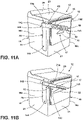
- FIGS. 11A-11B illustrate yet another exemplary accessory bar assembly 10 in the form of a rotatable bar.
- the accessory bar assembly 10 can be similar to the accessory bar assembly 10 and the accessory bar assembly 10.
- the accessory bar assembly 10 includes a single air bar 140 that is configured to swing about an attached, or upper end 142, which can be rotatably coupled with a side (e.g. side 16b) of the cabinet 16.
- the accessory bar assembly 10 can be moved from a vertically-oriented storage position 73a to a horizontally-oriented use position 73b.
- a free end 143 extends away from the cabinet 16.
- the side 16b of the cabinet 16 can include a depression 144 configured to receive and retain the accessory bar assembly 10.
- the air bar 140 includes the outlets 60.
- the air bar 140 defines an opening 146, or an aperture, configured to receive hangers and the like for suspending the articles 13 therefrom.
- the opening 146 can extend along at least a portion of the length of the air bar 140 at the free end 143.
- the accessory bar assembly 10 can be placed within the storage position 73a within a receptacle 78 that is defined within the surface of the cabinet 16.
- the accessory bar assembly 10 is typically externally visible.
- the accessory bar assembly 10 can also be visually camouflaged or otherwise obfuscated to blend in to the surrounding area of the cabinet 16.
- the receptacle 78 can also be defined within an interior portion of the cabinet 16.
- the accessory bar assembly 10 can retract, at least partially to an area within the cabinet 16.
- the accessory bar assembly 10, in this configuration can have an end piece that is externally visible, while the remainder of the accessory bar assembly 10 is stowed within the cabinet 16, until extracted from the receptacle 78.
- the laundry appliance 212 is a vertical axis laundry machine including a lid 214 rotatable between a raised position 211 to a lowered position 213, where the lid 214 selectively covers an access opening 216.
- the lid 214 can include a substantially flat, or planar, lower surface 218.
- the laundry appliance 212 can further include a panel 220 configured to be situated upon, or over, the access opening 216 to define a processing state that forms a wrinkle processing space 240.
- the panel 220 is typically removable or operable to be moved over the access opening 216 and away from the access opening 216.
- the panel 220 can include a substantially flat upper surface 222.
- the panel 220 is selectively attachable to the laundry appliance 212 and can include a tray configuration. Also, in certain aspects of the device, the panel 220 can be integral with the outer frame 215 of the lid 214 such that the outer frame 215 and the panel 220 defines the wrinkle processing space 240 between the lower surface 218 and the upper surface 222. In this manner, the lid 214 having the outer frame 215 the panel 220 forms a hinged configuration that allows for rotational separation of the lower surface 218 and the upper surface 222 to define the wrinkle processing space 240.
- the lower surface 218 and the upper surface 222 can be separated from each other to insert the article 13 therebetween and within the wrinkle processing space 240.
- the panel 220 can be removable from a storage space 217 defined by the lid 214 such that the panel 220 can be slid out from the storage space 217 of the lid 214 and placed over the access opening 216.
- the lower surface 218 and the upper surface 222 can be made of any suitable material, including, but not limited to, glass, ceramic, metals, various polymers, combinations thereof and other similar materials.
- a rail docking system 223 is provided, which can be located near a lid hinge area.
- the rail docking system 223 can selectively dock, or connect, the panel 220 to the laundry appliance 212.
- the rail docking system 223 can include a spring mechanism configured to couple the panel 220 to the laundry appliance 212. It is also contemplated that the panel 220 is electrically coupled to the laundry appliance 212 when docked. In this manner, the panel 220 can utilize electromagnetic induction that may not require a wired connection between the panel 220 and an assembly for delivering electrical power to heat the panel 220.
- a heating element 224 is configured to heat at least one of the lower surface 218 of the lid 214 and the upper surface 222 of the panel 220. In some aspects, both of the lower surface 218 of the lid 214 and the upper surface 222 of the panel 220 are heated. In some implementations, the heating element 224 includes hot water, typically in the form of steam. In such an aspect of the device, at least one of the lid 214 and the top panel 23 can include one or more steam nozzles that can be used to selectively direct one or more jets of steam onto the wrinkle processing space 240 to assist in the processing of laundry articles 13.
- the heating element 224 includes a plurality of electrically inductive or electrically resistive wires 226 integrated within the lid 214 and/or the panel 220. Additionally, the heating element 224 can provide a variable amount of heat. The heat used within the wrinkle processing space 240 can be produced by the heating element 224. It is also contemplated that at least a portion of the heat for the wrinkle processing space 240 can be delivered into the wrinkle processing space 240 from within the cabinet 16 of the laundry appliance 212, orfrom an external source, such as a drying appliance positioned near the laundry appliance 212 having the wrinkle processing space 240.
- the lower surface 218 of the lid 214 and the upper surface 222 of the panel 220 are pressed together upon closing of the lid 214.
- the lid 214 and the panel 220 work similar to an iron or clothing press to dry and smooth wrinkles from the article 13.
- the upper surface 222 and the lower surface 218 are generally parallel with one another.
- at least one of the upper surface 222 and the lower surface 218 can be able to conform to the general shape of the article 13 positioned within the wrinkle processing space 240.
- the lower surface 218 and/or the upper surface 222 can be attached to the panel 220 and the lid 214, respectively, via an operable connection, such as a ball joint that allows for some operable movement to define the wrinkle processing space 240.
- the use of the lid 214 and the panel 220 of the laundry appliance 212 can reduce or eliminate the need for an additional drying process, such as separate drying, ironing, refreshing or steaming.
- the laundry appliance 212 can include a runoff channel 230 configured to direct water removed from the article 13 into a drain or recirculation line of the laundry appliance 212.
- the laundry appliance 312 is a vertical axis laundry machine including a base that is incorporated within the cabinet 16.
- the cabinet 16 can also rest on a riser 314, or pedestal.
- the riser 314 is configured to lift the laundry appliance 312 off the floor surface.
- a drawer, or tray 316 can be disposed within the base and can be extendable from the cabinet 16 between a stowed position 315, within the base or within the riser 314, and a supporting position 317 in front of the cabinet 16.
- the tray 316 can also be configured to be disposed within the riser 314 and be extendable from the riser 314 and within an area below the cabinet 16.
- a step 320 is disposed within the tray 316.
- the step 320 can include a planar upper surface 322 that bears weight of a user.
- a user can pull the step 320 upwards to raise the step 320 from the flat position 319 to the step position 321.
- the laundry appliance 312 can include scissor hinge assemblies 324 on sides of the tray 316 that are configured to move the step 320 up to the step position 321 and down to the flat position 319. In the flat position 319, the tray 316 is nested within the tray 316 and is able to be operated between the stowed position 315 and the supporting position 317.
- the scissor hinge assemblies 324 such as a scissor linkage can include a first rod 330 and a second rod 332 crossed over each other in the shape of an "X.” The first rod 330 and the second rod 332 can be rotatably coupled at middle portions 333 thereof.
- a lower end 334 of each of the first and second rods 330, 332 can be fixed in positon relative to the tray 316.
- Upper ends 336 of each of the first and second rods 330, 332 can be slidably coupled to the step 320.
- the first and second rods 330, 332 can extend upwards to the step position 321 and lower to the flat position 319.
- the scissor hinge assemblies 324 can include a locking mechanism 340 configured to fix the step 320 in the step position 321 such that the step 320 can be configured to bear weight of a user.
- Benefits of various aspects described herein may include a variety of assemblies configured to dry articles 13 without using a conventional tumble dry process while also consolidating space utilized in a laundry area. Thus, air drying time may be decreased or eliminated. Additionally, a raised platform in the form of a step 320 integrated into a laundry appliance 12 may provide a user easier access to laundry items within the laundry appliance 12.
- a laundry appliance includes a cabinet.
- a blower is disposed within the cabinet that delivers accessory air through an accessory airflow path.
- An accessory bar assembly is in fluid communication with the accessory airflow path. The accessory bar assembly is configured to suspend articles therefrom and to provide the accessory air for conditioning the articles.
- the accessory bar assembly is in the form of a footwear dryer or a hanging-clothes dryer.
- the accessory airflow path includes a diverter valve that selectively delivers process air to the accessory airflow path.
- the blower also directs process air through a primary airflow path that includes a rotating drum.
- the accessory bar assembly extends from a front portion of the cabinet.
- the accessory air is directed within a processing space that is outside of the cabinet and proximate the front portion.
- the accessory bar assembly includes a plurality of perforations that direct the accessory air from the accessory airflow path and into the processing space.
- the accessory bar assembly includes an upper first air bar and a lower second air bar that are each connected to the accessory airflow path.
- the upper first air bar directs the accessory air in a downward direction and into a processing space.
- the lower second air bar directs the accessory air in an upward direction and into a processing space.
- the accessory bar assembly slidably extends from a receptacle defined within the cabinet.
- the receptacle is defined within an outer surface of the cabinet.
- the receptacle is defined within an interior of the cabinet.
- a vertical axis laundry machine includes a cabinet having a top panel that defines an access opening.
- a lid is coupled with the top panel and having a lower surface. The lid is operable between a raised position above the access opening and a lowered position that covers the access opening.
- a removable panel is selectively positioned on the top panel and over the access opening to define a processing state.
- a heating element is positioned proximate at least one of the lid and the top panel. The heating element is configured to heat at least one of the lower surface of the lid and an upper surface of the removable panel.
- one of the lid and the top panel includes a steam nozzle that selectively directs a jet of steam into the wrinkle processing space.
- the lid includes a planar lower surface and the removable panel includes a planar upper surface.
- the planar lower surface and the planar upper surface are parallel when the removable panel is in the processing state and the lid in the lowered position.
- the lower surface of the lid is operable relative to an outer frame of the lid.
- the lower surface of the lid is configured to conform to the upper surface of the removable panel in the processing state.
- the heating element is positioned within the lid and between the lower surface of the lid and the outer frame of the lid.
- a vertical axis laundry machine includes a cabinet that includes a base positioned proximate a lower portion of the cabinet.
- a drawer is disposed within the base and operable between a stowed position within the base and a supporting position forward of the base.
- a step is disposed within the drawer. The step is attached to the drawer via a scissor linkage. The step is configured to be operable between a flat position and a step position when the drawer is in the supporting position.
- the base is a pedestal that is separate from the cabinet.
- the pedestal supports the cabinet from below.
Landscapes
- Engineering & Computer Science (AREA)
- Textile Engineering (AREA)
- Accessory Of Washing/Drying Machine, Commercial Washing/Drying Machine, Other Washing/Drying Machine (AREA)
Applications Claiming Priority (2)
| Application Number | Priority Date | Filing Date | Title |
|---|---|---|---|
| US202163183205P | 2021-05-03 | 2021-05-03 | |
| US17/723,612 US12534846B2 (en) | 2021-05-03 | 2022-04-19 | Laundry appliance having laundry accessories |
Publications (2)
| Publication Number | Publication Date |
|---|---|
| EP4095309A2 true EP4095309A2 (de) | 2022-11-30 |
| EP4095309A3 EP4095309A3 (de) | 2023-03-01 |
Family
ID=81448502
Family Applications (1)
| Application Number | Title | Priority Date | Filing Date |
|---|---|---|---|
| EP22170986.8A Withdrawn EP4095309A3 (de) | 2021-05-03 | 2022-04-29 | Wäschereigerät mit wäschereizubehör |
Country Status (3)
| Country | Link |
|---|---|
| US (2) | US12534846B2 (de) |
| EP (1) | EP4095309A3 (de) |
| CN (1) | CN115369619A (de) |
Family Cites Families (38)
| Publication number | Priority date | Publication date | Assignee | Title |
|---|---|---|---|---|
| US3926315A (en) | 1975-01-10 | 1975-12-16 | Gen Motors Corp | Add-on clothes hanger for appliance |
| US4003138A (en) | 1975-09-23 | 1977-01-18 | Wicks Wayne M | Air curtain for clothes dryer |
| DE3211316A1 (de) | 1982-03-26 | 1983-09-29 | August Lepper GmbH, 5340 Bad Honnef | Haushaltsmaschine, insbesondere waschmaschine oder waschtrockner |
| JPH01145099A (ja) | 1987-11-30 | 1989-06-07 | Toshiba Corp | 洗濯機 |
| KR920008257A (ko) | 1990-10-23 | 1992-05-27 | 강진구 | 다림판 내장형 세탁기 |
| US5181685A (en) | 1991-10-09 | 1993-01-26 | Vladimir Ostapowicz | Collapsible hanger bar |
| JPH07213792A (ja) | 1994-02-04 | 1995-08-15 | Inax Corp | 仮物干し具 |
| JP3600106B2 (ja) | 2000-03-01 | 2004-12-08 | 株式会社日立製作所 | 衣類乾燥機 |
| US20070266740A9 (en) * | 2000-07-25 | 2007-11-22 | Kendall James W | Vertical laundry module |
| DE10259346A1 (de) | 2002-12-18 | 2004-07-08 | BSH Bosch und Siemens Hausgeräte GmbH | Vorrichtung zum Trocknen von Wäschestücken in Verbindung mit einem Kondensations-Haushaltswäschetrockner |
| CA2475811A1 (en) | 2003-08-18 | 2005-02-18 | Jean-Pierre Deblois | Handwear and footwear dryer rack with removable portable heater |
| US20070151304A1 (en) | 2005-12-30 | 2007-07-05 | Kendall James W | Modular laundry system with work surface having a functional insert |
| KR100662369B1 (ko) * | 2004-11-30 | 2007-01-02 | 엘지전자 주식회사 | 열풍공급용 옷걸이가 구비된 복합식 건조장치 |
| US7954914B2 (en) | 2005-12-30 | 2011-06-07 | Whirlpool Corporation | Retractable hanging element |
| DE602006002107D1 (de) | 2006-03-17 | 2008-09-18 | Electrolux Home Prod Corp | Haushaltmaschine für das Waschen oder Trocknen von Wäsche. |
| ES2327669T3 (es) | 2006-05-09 | 2009-11-02 | Electrolux Home Products Corporation N.V. | Electrodomestico. |
| KR20090102416A (ko) | 2008-03-26 | 2009-09-30 | 엘지전자 주식회사 | 세탁장치 |
| EP2194184A1 (de) | 2008-12-04 | 2010-06-09 | Electrolux Home Products Corporation N.V. | Vorrichtung zum Trocknen von Schuhen unter Verwendung eines Haushaltswäschetrockners |
| EP3425108B1 (de) | 2009-06-29 | 2020-12-16 | Electrolux Home Products Corporation N.V. | Vorrichtung zum wäschetrocknen |
| US8595952B2 (en) | 2010-06-30 | 2013-12-03 | Whirlpool Corporation | Integrated hanging solution |
| DE102011002330B3 (de) | 2011-04-29 | 2012-01-26 | Miele & Cie. Kg | Vorrichtung zur Vorhaltung von Wäschestücken an einer Wäschebehandlungsmaschine |
| US20120293052A1 (en) | 2011-05-16 | 2012-11-22 | Bsh Home Appliances Corporation | Work top and household appliance having a laundry hanging device |
| US8578639B2 (en) | 2011-06-27 | 2013-11-12 | Andrew C. Hurd | Fabric press |
| CN102677418A (zh) | 2012-05-09 | 2012-09-19 | 南京乐金熊猫电器有限公司 | 洗衣机 |
| KR102146019B1 (ko) | 2013-08-01 | 2020-08-20 | 삼성전자주식회사 | 건조장치를 구비한 세탁기 |
| KR102196313B1 (ko) * | 2014-08-12 | 2020-12-29 | 엘지전자 주식회사 | 의류처리장치 |
| KR102611054B1 (ko) | 2016-07-07 | 2023-12-07 | 엘지전자 주식회사 | 의류처리장치 |
| CN105970564A (zh) | 2016-07-26 | 2016-09-28 | 赵忠华 | 一种具备衣架卡位和温控功能的晾衣杆 |
| KR102747180B1 (ko) | 2016-12-08 | 2024-12-27 | 삼성전자주식회사 | 의류 건조기 |
| CN106835606A (zh) | 2016-12-30 | 2017-06-13 | 惠而浦(中国)股份有限公司 | 聚能顶盖烘干洗衣机 |
| US10100459B2 (en) | 2017-01-06 | 2018-10-16 | Whirlpool Corporation | Flexible drying solution for delivering clothing care externally of a drying appliance |
| EP3284856A1 (de) | 2017-12-01 | 2018-02-21 | V-Zug AG | Trommel- und raumlufttrockner mit einer anordnungsvorrichtung |
| CN110820263B (zh) * | 2018-08-13 | 2021-09-21 | 无锡小天鹅电器有限公司 | 衣物处理装置 |
| CN110878468B (zh) | 2018-09-05 | 2022-03-01 | 广东美的白色家电技术创新中心有限公司 | 衣物护理设备、衣物护理设备的控制方法 |
| US10774464B2 (en) | 2018-09-12 | 2020-09-15 | Haier Us Appliance Solutions, Inc. | Laundry appliance having an ironing assembly |
| US11767633B2 (en) | 2019-07-01 | 2023-09-26 | Whirlpool Corporation | Drying appliance having an accessory port for providing external airflow for powered accessories |
| CN112609403A (zh) * | 2020-12-24 | 2021-04-06 | 珠海格力电器股份有限公司 | 洗衣机盖、洗衣机及利用洗衣机盖熨烫的控制方法 |
| CN112609421A (zh) * | 2020-12-25 | 2021-04-06 | 珠海格力电器股份有限公司 | 熨烫装置、洗衣机及熨烫装置控制方法 |
-
2022
- 2022-04-19 US US17/723,612 patent/US12534846B2/en active Active
- 2022-04-28 CN CN202210470948.8A patent/CN115369619A/zh active Pending
- 2022-04-29 EP EP22170986.8A patent/EP4095309A3/de not_active Withdrawn
-
2025
- 2025-12-30 US US19/436,610 patent/US20260125844A1/en active Pending
Also Published As
| Publication number | Publication date |
|---|---|
| US12534846B2 (en) | 2026-01-27 |
| EP4095309A3 (de) | 2023-03-01 |
| US20220349111A1 (en) | 2022-11-03 |
| CN115369619A (zh) | 2022-11-22 |
| US20260125844A1 (en) | 2026-05-07 |
Similar Documents
| Publication | Publication Date | Title |
|---|---|---|
| RU2401348C2 (ru) | Гладильная доска с наклоняемой платформой | |
| US20080222909A1 (en) | Drying apparatus | |
| US20020133969A1 (en) | Air-flow dryer and method | |
| US7856743B2 (en) | Ironing board having an extendable and rectractable base | |
| WO2007128358A1 (en) | Household appliance | |
| US20210345839A1 (en) | Towel maintenance device | |
| WO2012129752A1 (zh) | 烘挂衣一体机 | |
| EP3933098A1 (de) | Wäschepflegevorrichtung und steuerungsverfahren dafür | |
| US12534846B2 (en) | Laundry appliance having laundry accessories | |
| CN101213337B (zh) | 可调节高度的烫衣板 | |
| CN109790676B (zh) | 干衣机 | |
| KR200463981Y1 (ko) | 상의 다림장치 | |
| KR20110021167A (ko) | 의류 처리 장치 및 의류 처리 장치 시스템 | |
| KR100595240B1 (ko) | 세탁물접이수단이 구비된 복합식 건조장치 | |
| EP3415678B1 (de) | Sekundärtrocknungskammer für einen wäschetrockner | |
| KR101822379B1 (ko) | 수납식 세탁물 건조대 | |
| JP2021058357A (ja) | 衣類処理装置 | |
| US20230146409A1 (en) | Automatic ironing apparatus | |
| JP2019030354A (ja) | 衣服仕上げ機 | |
| KR200307611Y1 (ko) | 의류 건조기용 빨래걸이구 | |
| KR20240138212A (ko) | 의류 관리기 |
Legal Events
| Date | Code | Title | Description |
|---|---|---|---|
| PUAI | Public reference made under article 153(3) epc to a published international application that has entered the european phase |
Free format text: ORIGINAL CODE: 0009012 |
|
| STAA | Information on the status of an ep patent application or granted ep patent |
Free format text: STATUS: THE APPLICATION HAS BEEN PUBLISHED |
|
| AK | Designated contracting states |
Kind code of ref document: A2 Designated state(s): AL AT BE BG CH CY CZ DE DK EE ES FI FR GB GR HR HU IE IS IT LI LT LU LV MC MK MT NL NO PL PT RO RS SE SI SK SM TR |
|
| PUAL | Search report despatched |
Free format text: ORIGINAL CODE: 0009013 |
|
| AK | Designated contracting states |
Kind code of ref document: A3 Designated state(s): AL AT BE BG CH CY CZ DE DK EE ES FI FR GB GR HR HU IE IS IT LI LT LU LV MC MK MT NL NO PL PT RO RS SE SI SK SM TR |
|
| RIC1 | Information provided on ipc code assigned before grant |
Ipc: D06F 57/12 20060101ALN20230123BHEP Ipc: D06F 39/12 20060101ALN20230123BHEP Ipc: D06F 58/20 20060101AFI20230123BHEP |
|
| RAP3 | Party data changed (applicant data changed or rights of an application transferred) |
Owner name: WHIRLPOOL CORPORATION |
|
| P01 | Opt-out of the competence of the unified patent court (upc) registered |
Effective date: 20230821 |
|
| STAA | Information on the status of an ep patent application or granted ep patent |
Free format text: STATUS: THE APPLICATION IS DEEMED TO BE WITHDRAWN |
|
| 18D | Application deemed to be withdrawn |
Effective date: 20230902 |