EP4094652B1 - Selbstverriegelnde struktur für toilettenstossdämpfer - Google Patents
Selbstverriegelnde struktur für toilettenstossdämpfer Download PDFInfo
- Publication number
- EP4094652B1 EP4094652B1 EP22164468.5A EP22164468A EP4094652B1 EP 4094652 B1 EP4094652 B1 EP 4094652B1 EP 22164468 A EP22164468 A EP 22164468A EP 4094652 B1 EP4094652 B1 EP 4094652B1
- Authority
- EP
- European Patent Office
- Prior art keywords
- elastic
- hole
- toilet
- accommodation
- hinge shaft
- Prior art date
- Legal status (The legal status is an assumption and is not a legal conclusion. Google has not performed a legal analysis and makes no representation as to the accuracy of the status listed.)
- Active
Links
Images



Classifications
-
- A—HUMAN NECESSITIES
- A47—FURNITURE; DOMESTIC ARTICLES OR APPLIANCES; COFFEE MILLS; SPICE MILLS; SUCTION CLEANERS IN GENERAL
- A47K—SANITARY EQUIPMENT; ACCESSORIES THEREFOR, e.g. TOILET ACCESSORIES
- A47K13/00—Seats or covers for all kinds of closets
- A47K13/12—Hinges
-
- A—HUMAN NECESSITIES
- A47—FURNITURE; DOMESTIC ARTICLES OR APPLIANCES; COFFEE MILLS; SPICE MILLS; SUCTION CLEANERS IN GENERAL
- A47K—SANITARY EQUIPMENT; ACCESSORIES THEREFOR, e.g. TOILET ACCESSORIES
- A47K13/00—Seats or covers for all kinds of closets
- A47K13/24—Parts or details not covered in, or of interest apart from, groups A47K13/02 - A47K13/22
Definitions
- the present disclosure relates to the technical field of toilet, in particular to a self-locking structure for toilet bumper.
- Document CN 107 348 892 A discloses a self-locking structure for a toilet bumper.
- the bumper of toilet seat in the market needs to be fixed by additional assembly of decorative ring, snap ring, snap nails and other parts.
- the installation way is to provide corresponding holding slots on the cover plate for the installation of snap nails and decorative rings, or install snap rings between the seat ring and the cover plate, but the structure has the following disadvantages: 1.
- the gap between the cover plate and the seat ring is too large and the flip stability is poor; 2. It is not only troublesome to assemble, but also increases the operating hours. At the same time, it is difficult to disassemble.
- the cover plate or seat ring is often scratched, which leads to the scrapping of parts and the increase of production cost.
- the present disclosure provides a self-locking structure for a toilet bumper.
- a self-locking structure for a toilet bumper including a fixed seat fixedly arranged on a toilet and a cover plate rotatably arranged on the fixed seat, a mounting hole is arranged on the cover plate, and a seat hinge assembly configured for hinged connection between the fixed seat and the cover plate is installed in the mounting hole, wherein the seat hinge assembly includes a hinge shaft, a first accommodation slot is provided on a peripheral surface of the hinge shaft, an elastic buckle partially protruding out of the first accommodation slot is provided in the first accommodation slot, the mounting hole is provided with an annular flange inwardly protruding at an opening of the mounting hole; the elastic buckle includes a base part, an elastic part and an guide part; one side of the base part is fixedly connected with the elastic part, and the other side of the base part is fixedly connected with the guide part; during assembly, the guide part of the elastic buckle is guided into the mounting hole from outside to inside along an axial direction of the mounting hole, so that
- one side of the guide part is a guide inclined plane .
- the elastic buckle includes a disassembly part fixedly arranged on a side of the base part, an outer circumference of the hinge shaft is fixedly sleeved with a sleeve; and the disassembly part abuts against an inner side wall of the sleeve under an elastic action of the elastic part after assembly.
- the elastic part is divided into a first elastic part and a second elastic part, and the first elastic part and the second elastic part bend towards each other to form a rhombus shape; and the first elastic part and the second elastic part are separated from each other, so that the elastic part forms a first opening.
- the fixed seat is fixedly provided with a connection column
- the circumference of the hinge shaft is provided with an accommodation hole for an insertion of the connection column
- an end surface of the hinge shaft is provided with a second accommodation slot communicated with the accommodation hole; after the connection column is inserted into the accommodation hole, the connection column is clamped with the hinge shaft through a fastener.
- the fastener is provided with an annular insertion block inserted into the second accommodation slot, and an insertion end of the annular insertion block is provided with a second opening; an inner side of the annular insertion block close to the second opening is provided with an inwardly protruding rib, a circumference of the connection column is recessed inwardly to form a clamping groove for the insertion of the rib, and the sleeve is provided with a through hole for the connection column to pass through and through hole is opposite to the accommodation hole; one end of the connection column is inserted into the annular insertion block through the through hole and the accommodation hole in sequence, and is clamped with the rib through the clamping groove.
- strip-shaped insertion blocks are symmetrically arranged on the fastener, a third accommodation slot for the corresponding insertion of the strip-shaped insertion blocks is arranged on an end face of the hinge shaft, and a first hook is arranged at an insertion end of the strip-shaped insertion block; a second hook is arranged in the third accommodation slot, and the strip-shaped insertion block is engaged with the second hook in the third accommodation slot through the first hook.
- the present disclosure improves some parts of the hinge shaft in the bumper, and an elastic buckle is placed in the hinge shaft, which can quickly complete the disassembly and assembly of the bumper.
- the elastic buckle has the advantages in light weight, small occupied space and little impact on the strength of the hinge shaft.
- the present disclosure can complete the fixed installation of the bumper without using snap nails, snap rings, decorative rings and other parts on the cover plate, further shorten the length of the bumper and increase the distance between the mounting holes on both sides of the cover plate, so as to improve the swing stability of the whole toilet.
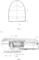
- a self-locking structure for a toilet bumper includes a fixed seat 1 fixedly arranged on the toilet and a cover plate 2 rotatably arranged on the fixed seat 1, the cover plate 2 is provided with a mounting hole 21, and the mounting hole 21 is provided with a seat hinge assembly 3 for the hinge between the fixed seat 1 and the cover plate 2.
- the seat hinge assembly 3 includes a hinge shaft 31.
- the peripheral surface of the hinge shaft 31 is provided with a first accommodation slot 311, and the first accommodation slot 311 contains an elastic buckle 32 which partially extends out of the first accommodation slot 311.
- the opening of the mounting hole 21 is provided with an inward protruding annular flange 211.
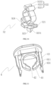
- the elastic buckle 32 includes a base part 321, an elastic part 322 and an guide part 323. One side of the base part 321 is fixedly connected with the elastic part 322, and the other side of the base part 321 is fixedly connected with the guide part 323.
- the guide part 323 of the elastic buckle 32 is guided into the mounting hole 21 from outside to inside along the axis direction of the mounting hole 21, so that the guide part 323 can be against the annular flange 211 in the axis direction of the mounting hole 21, thereby limiting the axial movement of the seat hinge assembly 3.
- the present disclosure improves some parts of the hinge shaft 31 in the bumper.
- the elastic buckle 32 is placed in the hinge shaft 31, which can quickly complete the disassembly and assembly of the bumper.
- the elastic buckle 32 has the advantages in light weight, small occupied space and little impact on the strength of the hinge shaft 31.
- the present disclosure can complete the fixed installation of the bumper without using snap nails, snap rings, decorative rings and other parts on the cover plate 2, further shorten the length of the bumper, and increase the distance between the mounting holes 21 on both sides of the cover plate 2, so as to improve the swing stability of the whole toilet.
- one side of the guide part 323 is a guide inclined plane 3231, which is convenient for the guide part 323 to be clamped into the mounting hole 21, while the other side of the guide part 323 is configured for butting the annular flange 211, so as to fix the axial direction of the whole seat hinge assembly 3.
- the length of the base part 321 is equivalent to the radial width of the first accommodation slot 311 to limit the left and right shaking of the elastic buckle 32, so as to facilitate the smooth up and down compression of the elastic buckle 32.
- the elastic buckle 32 includes a disassembly part 324 fixedly arranged on the side of the base part 321, and the outer circumference of the hinge shaft 31 is fixedly sleeved with a sleeve 33. And the disassembly part 324 abuts against the inner side wall of the sleeve 33 under an elastic action of the elastic part 322 after assembly. After the elastic part 322 of the elastic buckle 32 is compressed, the disassembly part 324 abuts against the inner wall of the sleeve 33.
- the sleeve 33 mainly plays a limiting role to prevent the elastic buckle 32 from falling out, so that the user can complete the fixation of the bumper without adding snap nails, decorative rings, snap rings and other parts.
- the connection column 11 When the connection column 11 is not inserted, the user can press the disassembly part 324 through the through hole 331 of the sleeve 33, so that the guide part 323 is separated from the annular flange 211.
- the elastic buckle 32 is separated from the axial fixation, so that the whole seat hinge assembly 3 can be disassembled.
- the elastic buckle 32 makes the installation and disassembly of the bumper more convenient.
- the elastic part 322 is divided into a first elastic part 3221 and a second elastic part 3222.
- the first elastic part 3221 and the second elastic part 3222 bend towards each other to form a rhombus shape.
- the first elastic part 3221 and the second elastic part 3222 are separated from each other, so that the elastic part 322 forms a first opening 3223, which facilitates the insertion and elastic deformation of the elastic buckle 32.
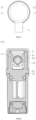
- the fixed seat 1 is fixedly provided with a connection column 11, the circumference of the hinge shaft 31 is provided with an accommodation hole 312 for the insertion of the connection column 11, and the end surface of the hinge shaft 31 is provided with a second accommodation slot 313 communicated with the accommodation hole 312.
- the connection column 11 is clamped with the hinge shaft 31 through a fastener 4.
- the fastener 4 is provided with an annular insertion block 41 inserted into the second accommodation slot 313, and the insertion end of the annular insertion block 41 is provided with a second opening 42.
- the inner side of the annular insertion block 41 close to the second opening 42 is provided with an inwardly protruding rib 411, and the circumference of the connection column 11 is recessed inwardly to form a clamping groove 111 for the insertion of the rib 411.
- the sleeve 33 is provided with a through hole 331 for the connection column 11 to pass through and through hole 331 is opposite to the accommodation hole 312.
- One end of the connection column 11 is inserted into the annular opening of the annular insertion block 41 through the through hole 331 and the accommodation hole 312 in sequence, and is clamped with the rib 411 through the clamping groove 111, so as to reach a clamping action.
- connection column 11 can support the buckle position of the annular insertion block 41 during insertion.
- the user can forcefully pull out the cover plate 2.
- the buckle position of the fastener 4 is extended outward to a certain extent, and then the connection column 11 can be pulled out.
- the upper and lower ends of the rib 411 have a certain inclination for the insertion or extraction of the connection column 11, which also improves the deformation difficulty, thus realizing that the connection column 11 can be repeatedly forced to insertion and extract, and still maintain the buckling stability.
- it also eliminates the need for spring assembly, thus effectively improving the assembly efficiency of the assembly.
- strip-shaped insertion blocks 43 are symmetrically arranged on the fastener 4, a third accommodation slot 314 for the corresponding insertion of the strip-shaped insertion block 43 is arranged on the end face of the hinge shaft 31.
- a first hook 431 is arranged at the insertion end of the strip-shaped insertion block 43, and a second hook 3141 is arranged in the third accommodation slot 314.
- the strip-shaped insertion block 43 is engaged with the second hook 3141 in the third accommodation slot 314 through the first hook 431, and is clamped in a snap way to facilitate assembly and fixation.
Landscapes
- Health & Medical Sciences (AREA)
- Public Health (AREA)
- Toilet Supplies (AREA)
- Insertion Pins And Rivets (AREA)
- Vehicle Waterproofing, Decoration, And Sanitation Devices (AREA)
- Vibration Dampers (AREA)
Claims (6)
- Selbstverriegelungsstruktur für einen Toilettenstoßfänger, umfassend einen festen Sitz (1), der fest an einer Toilette angeordnet ist und eine Abdeckplatte (2), die drehbar an dem festen Sitz (1) angeordnet ist, wobei eine Montageloch (21) an der Abdeckplatte (2) angeordnet ist und eine Sitzgelenkbaugruppe (3), die für eine Gelenkverbindung zwischen dem festen Sitz (1) und der Abdeckplatte (2) konfiguriert ist, in dem Montageloch (21) installiert ist, wobei die Sitzgelenkbaugruppe (3) eine Gelenkwelle (31) umfasst, wobei ein erster Aufnahmeschlitz (311) an einer Umfangsfläche der Gelenkwelle (31) bereitgestellt ist und eine elastische Halterung (32), die teilweise aus dem ersten Aufnahmeschlitz (311) ragt, in dem ersten Aufnahmeschlitz (311) bereitgestellt ist;
wobei die elastische Halterung (32) einen Sockelteil (321), einen elastischen Teil (322) und einen Führungsteil (323) umfasst, wobei eine Seite des Sockelteils (321) fest mit dem elastischen Teil (322) verbunden ist und die andere Seite des Sockelteils (321) fest mit dem Führungsteil (323) verbunden ist; dadurch gekennzeichnet, dass das Montageloch (21) mit einem ringförmigen Flansch (211) versehen ist, der an einer Öffnung des Montagelochs (21) nach innen vorspringt; und dass während der Montage der Führungsteil (323) der elastischen Halterung (32) von außen entlang einer Axialrichtung des Montagelochs (21) in das Montageloch (21) hinein geführt wird, sodass der Führungsteil (323) in der Axialrichtung des Montagelochs (21) am ringförmigen Flansch (211) anliegt, wodurch eine axiale Bewegung der Sitzgelenkbaugruppe (3) begrenzt wird, wobei eine Seite des Führungsteils (323) eine geneigte Führungsebene (3231) ist. - Selbstverriegelungsstruktur für einen Toilettenstoßfänger nach Anspruch 1, dadurch gekennzeichnet, dass die elastische Halterung (32) einen Demontageteil (324) umfasst, der fest an einer Seite des Sockelteils (321) angeordnet ist, eine Hülse (33) fest auf einen Außenumfang der Gelenkwelle (31) gesetzt ist; und der Demontageteil (324) nach der Montage unter Einwirkung des elastischen Teils (322) an einer Innenwand der Hülse (33) anliegt.
- Selbstverriegelungsstruktur für einen Toilettenstoßfänger nach Anspruch 1, dadurch gekennzeichnet, dass der elastische Teil (322) in einen ersten elastischen Teil (3221) und einen zweiten elastische Teil (3222) unterteilt ist und der erste elastische Teil (3221) und der zweite elastische Teil (3222) zueinander hin gebogen sind, um eine Rhombenform zu bilden, und der erste elastische Teil (3221) und der zweite elastische Teil (3222) voneinander getrennt sind, sodass der elastische Teil (322) eine erste Aussparung (3223) bildet.
- Selbstverriegelungsstruktur für einen Toilettenstoßfänger nach Anspruch 3, dadurch gekennzeichnet, dass der feste Sitz (1) mit einer fest angeordneten Verbindungssäule (11) versehen ist, der Umfang der Gelenkwelle (31) mit einem Aufnahmeloch (312) zum Einführen der Verbindungssäule (11) versehen ist und eine Endfläche der Gelenkwelle (31) mit einem zweiten Aufnahmeschlitz (313) versehen ist, der mit dem Aufnahmeloch (312) in Verbindung steht; wobei nach dem Einführen der Verbindungssäule (11) in das Aufnahmeloch (312) die Verbindungssäule (11) durch ein Befestigungselement (4) mit der Gelenkwelle (31) festgeklemmt ist.
- Selbstverriegelungsstruktur für einen Toilettenstoßfänger nach Anspruch 4, dadurch gekennzeichnet, dass das Befestigungselement (4) mit einem ringförmigen Einführblock (41) versehen ist, der in den zweiten Aufnahmeschlitz (313) eingeführt ist, und ein Einführende des ringförmigen Einführblocks (41) mit einer zweiten Öffnung (42) versehen ist; wobei eine Innenseite des ringförmigen Einführblocks (41) nah an der zweiten Öffnung (42) mit einer nach innen vorspringenden Rippe (411) versehen ist, ein Umfang der Verbindungssäule (11) nach innen vertieft ist, um eine Klemmnut (111) zum Einführen der Rippe (411) zu bilden, und die Hülse (33) mit einem Durchgangsloch (331) für die Verbindungssäule (11) versehen ist und das Durchgangsloch (331) dem Aufnahmeloch (312) gegenüberliegt; wobei ein Ende der Verbindungssäule (11) nacheinander durch das Durchgangsloch (331) und das Aufnahmeloch (312) in den ringförmigen Einführblock (41) eingeführt ist und durch die Klemmnut (111) mit der Rippe festgeklemmt ist.
- Selbstverriegelungsstruktur für einen Toilettenstoßfänger nach Anspruch 5, dadurch gekennzeichnet, dass streifenförmige Einführblöcke (43) symmetrisch an dem Befestigungselement (4) angeordnet sind, ein dritter Aufnahmeschlitz (314) zum entsprechenden Einführen der streifenförmigen Einführblöcke (43) an einer Endfläche der Gelenkwelle (31) angeordnet sind und ein erster Haken (431) an einem Einführende des streifenförmige Einführblocks (43) angeordnet ist; wobei ein zweiter Haken (3141) in dem dritten Aufnahmeschlitz (314) angeordnet ist und der streifenförmige Einführblock (43) mit dem zweiten Haken (3141) in dem dritten Aufnahmeschlitz (314) durch den ersten Haken (431) in Eingriff steht.
Applications Claiming Priority (1)
| Application Number | Priority Date | Filing Date | Title |
|---|---|---|---|
| CN202121150107.6U CN215424371U (zh) | 2021-05-26 | 2021-05-26 | 一种用于马桶缓冲器的自锁结构 |
Publications (3)
| Publication Number | Publication Date |
|---|---|
| EP4094652A1 EP4094652A1 (de) | 2022-11-30 |
| EP4094652B1 true EP4094652B1 (de) | 2023-07-05 |
| EP4094652C0 EP4094652C0 (de) | 2023-07-05 |
Family
ID=79708477
Family Applications (1)
| Application Number | Title | Priority Date | Filing Date |
|---|---|---|---|
| EP22164468.5A Active EP4094652B1 (de) | 2021-05-26 | 2022-03-25 | Selbstverriegelnde struktur für toilettenstossdämpfer |
Country Status (3)
| Country | Link |
|---|---|
| EP (1) | EP4094652B1 (de) |
| CN (1) | CN215424371U (de) |
| ES (1) | ES2952707T3 (de) |
Family Cites Families (1)
| Publication number | Priority date | Publication date | Assignee | Title |
|---|---|---|---|---|
| CN107348892B (zh) * | 2017-07-26 | 2020-06-02 | 厦门倍杰特科技股份公司 | 一种无按键快速拆装盖板 |
-
2021
- 2021-05-26 CN CN202121150107.6U patent/CN215424371U/zh active Active
-
2022
- 2022-03-25 ES ES22164468T patent/ES2952707T3/es active Active
- 2022-03-25 EP EP22164468.5A patent/EP4094652B1/de active Active
Also Published As
| Publication number | Publication date |
|---|---|
| ES2952707T3 (es) | 2023-11-03 |
| EP4094652A1 (de) | 2022-11-30 |
| CN215424371U (zh) | 2022-01-07 |
| EP4094652C0 (de) | 2023-07-05 |
Similar Documents
| Publication | Publication Date | Title |
|---|---|---|
| US20050263655A1 (en) | Bathroom Accessory Mounting Assembly and Method of Mounting | |
| KR20040025005A (ko) | 착탈성이 우수한 이동식 막사의 결합부재 | |
| CN216641796U (zh) | 一种柜门反弹器 | |
| EP4094652A1 (de) | Selbstverriegelnde struktur für toilettenstossdämpfer | |
| CN203263271U (zh) | 一种马桶盖板与马桶座体的连接机构 | |
| CN210370292U (zh) | 一种马桶盖板铰接组件 | |
| CN219544423U (zh) | 箱包避震轮架组件 | |
| EP4094654B1 (de) | Scharnierstruktur für toilettendeckelplatte | |
| CN109017177B (zh) | 一种拖钩盖板结构 | |
| EP4094653B1 (de) | Scharnierstruktur für toilettendeckelplatte | |
| CN210807848U (zh) | 电子设备的壳体组件及电子设备 | |
| CN208580351U (zh) | 一种用于家用电器的旋钮结构 | |
| CN209996186U (zh) | 一种马桶盖板装配结构 | |
| CN214265454U (zh) | 通用型安装手柄 | |
| CN223577340U (zh) | 一种折叠房屋用板材锁定件、框架以及底板 | |
| CN215000449U (zh) | 一种具有旋钮开关的按压式快拆底座及显示器组件 | |
| CN215216514U (zh) | 冷风扇 | |
| CN218514522U (zh) | 一种便于安装的无线ap设备 | |
| CN213129098U (zh) | 底盖快速安装的电饭煲 | |
| CN214659407U (zh) | 一种锁扣盒 | |
| CN218063008U (zh) | 一种易于拆卸的汽车铆钉 | |
| CN220309048U (zh) | 马桶盖板上使用的传动轴组件 | |
| CN219888427U (zh) | 伸缩套管的定位结构 | |
| CN214034483U (zh) | 一种叶状柱板材及其安装结构 | |
| CN223682455U (zh) | 马桶盖快拆结构 |
Legal Events
| Date | Code | Title | Description |
|---|---|---|---|
| PUAI | Public reference made under article 153(3) epc to a published international application that has entered the european phase |
Free format text: ORIGINAL CODE: 0009012 |
|
| STAA | Information on the status of an ep patent application or granted ep patent |
Free format text: STATUS: REQUEST FOR EXAMINATION WAS MADE |
|
| 17P | Request for examination filed |
Effective date: 20220325 |
|
| AK | Designated contracting states |
Kind code of ref document: A1 Designated state(s): AL AT BE BG CH CY CZ DE DK EE ES FI FR GB GR HR HU IE IS IT LI LT LU LV MC MK MT NL NO PL PT RO RS SE SI SK SM TR |
|
| GRAP | Despatch of communication of intention to grant a patent |
Free format text: ORIGINAL CODE: EPIDOSNIGR1 |
|
| STAA | Information on the status of an ep patent application or granted ep patent |
Free format text: STATUS: GRANT OF PATENT IS INTENDED |
|
| RIC1 | Information provided on ipc code assigned before grant |
Ipc: A47K 13/26 20060101ALI20230119BHEP Ipc: A47K 13/24 20060101ALI20230119BHEP Ipc: A47K 13/12 20060101AFI20230119BHEP |
|
| INTG | Intention to grant announced |
Effective date: 20230213 |
|
| GRAS | Grant fee paid |
Free format text: ORIGINAL CODE: EPIDOSNIGR3 |
|
| GRAA | (expected) grant |
Free format text: ORIGINAL CODE: 0009210 |
|
| STAA | Information on the status of an ep patent application or granted ep patent |
Free format text: STATUS: THE PATENT HAS BEEN GRANTED |
|
| AK | Designated contracting states |
Kind code of ref document: B1 Designated state(s): AL AT BE BG CH CY CZ DE DK EE ES FI FR GB GR HR HU IE IS IT LI LT LU LV MC MK MT NL NO PL PT RO RS SE SI SK SM TR |
|
| REG | Reference to a national code |
Ref country code: CH Ref legal event code: EP |
|
| REG | Reference to a national code |
Ref country code: AT Ref legal event code: REF Ref document number: 1584014 Country of ref document: AT Kind code of ref document: T Effective date: 20230715 |
|
| REG | Reference to a national code |
Ref country code: DE Ref legal event code: R096 Ref document number: 602022000170 Country of ref document: DE |
|
| REG | Reference to a national code |
Ref country code: IE Ref legal event code: FG4D |
|
| U01 | Request for unitary effect filed |
Effective date: 20230717 |
|
| U07 | Unitary effect registered |
Designated state(s): AT BE BG DE DK EE FI FR IT LT LU LV MT NL PT SE SI Effective date: 20230725 |
|
| REG | Reference to a national code |
Ref country code: LT Ref legal event code: MG9D |
|
| REG | Reference to a national code |
Ref country code: ES Ref legal event code: FG2A Ref document number: 2952707 Country of ref document: ES Kind code of ref document: T3 Effective date: 20231103 |
|
| PG25 | Lapsed in a contracting state [announced via postgrant information from national office to epo] |
Ref country code: GR Free format text: LAPSE BECAUSE OF FAILURE TO SUBMIT A TRANSLATION OF THE DESCRIPTION OR TO PAY THE FEE WITHIN THE PRESCRIBED TIME-LIMIT Effective date: 20231006 |
|
| PG25 | Lapsed in a contracting state [announced via postgrant information from national office to epo] |
Ref country code: IS Free format text: LAPSE BECAUSE OF FAILURE TO SUBMIT A TRANSLATION OF THE DESCRIPTION OR TO PAY THE FEE WITHIN THE PRESCRIBED TIME-LIMIT Effective date: 20231105 |
|
| PG25 | Lapsed in a contracting state [announced via postgrant information from national office to epo] |
Ref country code: RS Free format text: LAPSE BECAUSE OF FAILURE TO SUBMIT A TRANSLATION OF THE DESCRIPTION OR TO PAY THE FEE WITHIN THE PRESCRIBED TIME-LIMIT Effective date: 20230705 Ref country code: NO Free format text: LAPSE BECAUSE OF FAILURE TO SUBMIT A TRANSLATION OF THE DESCRIPTION OR TO PAY THE FEE WITHIN THE PRESCRIBED TIME-LIMIT Effective date: 20231005 Ref country code: IS Free format text: LAPSE BECAUSE OF FAILURE TO SUBMIT A TRANSLATION OF THE DESCRIPTION OR TO PAY THE FEE WITHIN THE PRESCRIBED TIME-LIMIT Effective date: 20231105 Ref country code: HR Free format text: LAPSE BECAUSE OF FAILURE TO SUBMIT A TRANSLATION OF THE DESCRIPTION OR TO PAY THE FEE WITHIN THE PRESCRIBED TIME-LIMIT Effective date: 20230705 Ref country code: GR Free format text: LAPSE BECAUSE OF FAILURE TO SUBMIT A TRANSLATION OF THE DESCRIPTION OR TO PAY THE FEE WITHIN THE PRESCRIBED TIME-LIMIT Effective date: 20231006 |
|
| PG25 | Lapsed in a contracting state [announced via postgrant information from national office to epo] |
Ref country code: PL Free format text: LAPSE BECAUSE OF FAILURE TO SUBMIT A TRANSLATION OF THE DESCRIPTION OR TO PAY THE FEE WITHIN THE PRESCRIBED TIME-LIMIT Effective date: 20230705 |
|
| REG | Reference to a national code |
Ref country code: DE Ref legal event code: R097 Ref document number: 602022000170 Country of ref document: DE |
|
| U20 | Renewal fee for the european patent with unitary effect paid |
Year of fee payment: 3 Effective date: 20240318 |
|
| PG25 | Lapsed in a contracting state [announced via postgrant information from national office to epo] |
Ref country code: SM Free format text: LAPSE BECAUSE OF FAILURE TO SUBMIT A TRANSLATION OF THE DESCRIPTION OR TO PAY THE FEE WITHIN THE PRESCRIBED TIME-LIMIT Effective date: 20230705 Ref country code: RO Free format text: LAPSE BECAUSE OF FAILURE TO SUBMIT A TRANSLATION OF THE DESCRIPTION OR TO PAY THE FEE WITHIN THE PRESCRIBED TIME-LIMIT Effective date: 20230705 Ref country code: CZ Free format text: LAPSE BECAUSE OF FAILURE TO SUBMIT A TRANSLATION OF THE DESCRIPTION OR TO PAY THE FEE WITHIN THE PRESCRIBED TIME-LIMIT Effective date: 20230705 Ref country code: SK Free format text: LAPSE BECAUSE OF FAILURE TO SUBMIT A TRANSLATION OF THE DESCRIPTION OR TO PAY THE FEE WITHIN THE PRESCRIBED TIME-LIMIT Effective date: 20230705 |
|
| PLBE | No opposition filed within time limit |
Free format text: ORIGINAL CODE: 0009261 |
|
| STAA | Information on the status of an ep patent application or granted ep patent |
Free format text: STATUS: NO OPPOSITION FILED WITHIN TIME LIMIT |
|
| 26N | No opposition filed |
Effective date: 20240408 |
|
| PG25 | Lapsed in a contracting state [announced via postgrant information from national office to epo] |
Ref country code: MC Free format text: LAPSE BECAUSE OF FAILURE TO SUBMIT A TRANSLATION OF THE DESCRIPTION OR TO PAY THE FEE WITHIN THE PRESCRIBED TIME-LIMIT Effective date: 20230705 |
|
| PG25 | Lapsed in a contracting state [announced via postgrant information from national office to epo] |
Ref country code: MC Free format text: LAPSE BECAUSE OF FAILURE TO SUBMIT A TRANSLATION OF THE DESCRIPTION OR TO PAY THE FEE WITHIN THE PRESCRIBED TIME-LIMIT Effective date: 20230705 |
|
| PG25 | Lapsed in a contracting state [announced via postgrant information from national office to epo] |
Ref country code: IE Free format text: LAPSE BECAUSE OF NON-PAYMENT OF DUE FEES Effective date: 20240325 |
|
| PG25 | Lapsed in a contracting state [announced via postgrant information from national office to epo] |
Ref country code: IE Free format text: LAPSE BECAUSE OF NON-PAYMENT OF DUE FEES Effective date: 20240325 |
|
| U20 | Renewal fee for the european patent with unitary effect paid |
Year of fee payment: 4 Effective date: 20250226 |
|
| PGFP | Annual fee paid to national office [announced via postgrant information from national office to epo] |
Ref country code: ES Payment date: 20250404 Year of fee payment: 4 |
|
| PG25 | Lapsed in a contracting state [announced via postgrant information from national office to epo] |
Ref country code: CY Free format text: LAPSE BECAUSE OF FAILURE TO SUBMIT A TRANSLATION OF THE DESCRIPTION OR TO PAY THE FEE WITHIN THE PRESCRIBED TIME-LIMIT; INVALID AB INITIO Effective date: 20220325 |
|
| REG | Reference to a national code |
Ref country code: CH Ref legal event code: H13 Free format text: ST27 STATUS EVENT CODE: U-0-0-H10-H13 (AS PROVIDED BY THE NATIONAL OFFICE) Effective date: 20251023 |
|
| PG25 | Lapsed in a contracting state [announced via postgrant information from national office to epo] |
Ref country code: TR Free format text: LAPSE BECAUSE OF FAILURE TO SUBMIT A TRANSLATION OF THE DESCRIPTION OR TO PAY THE FEE WITHIN THE PRESCRIBED TIME-LIMIT Effective date: 20230705 |
|
| PG25 | Lapsed in a contracting state [announced via postgrant information from national office to epo] |
Ref country code: CH Free format text: LAPSE BECAUSE OF NON-PAYMENT OF DUE FEES Effective date: 20250331 |
|
| U20 | Renewal fee for the european patent with unitary effect paid |
Year of fee payment: 5 Effective date: 20260214 |
|
| PGFP | Annual fee paid to national office [announced via postgrant information from national office to epo] |
Ref country code: GB Payment date: 20260226 Year of fee payment: 5 |