EP4092709B1 - Elektromagnetisches schütz - Google Patents
Elektromagnetisches schütz Download PDFInfo
- Publication number
- EP4092709B1 EP4092709B1 EP20914456.7A EP20914456A EP4092709B1 EP 4092709 B1 EP4092709 B1 EP 4092709B1 EP 20914456 A EP20914456 A EP 20914456A EP 4092709 B1 EP4092709 B1 EP 4092709B1
- Authority
- EP
- European Patent Office
- Prior art keywords
- coupling part
- fastening hole
- coupled
- cover
- lower frame
- Prior art date
- Legal status (The legal status is an assumption and is not a legal conclusion. Google has not performed a legal analysis and makes no representation as to the accuracy of the status listed.)
- Active
Links
Images



Classifications
-
- H—ELECTRICITY
- H01—ELECTRIC ELEMENTS
- H01H—ELECTRIC SWITCHES; RELAYS; SELECTORS; EMERGENCY PROTECTIVE DEVICES
- H01H50/00—Details of electromagnetic relays
- H01H50/02—Bases; Casings; Covers
- H01H50/04—Mounting complete relay or separate parts of relay on a base or inside a case
- H01H50/041—Details concerning assembly of relays
-
- H—ELECTRICITY
- H01—ELECTRIC ELEMENTS
- H01H—ELECTRIC SWITCHES; RELAYS; SELECTORS; EMERGENCY PROTECTIVE DEVICES
- H01H50/00—Details of electromagnetic relays
- H01H50/02—Bases; Casings; Covers
- H01H50/04—Mounting complete relay or separate parts of relay on a base or inside a case
- H01H50/047—Details concerning mounting a relays
-
- H—ELECTRICITY
- H01—ELECTRIC ELEMENTS
- H01H—ELECTRIC SWITCHES; RELAYS; SELECTORS; EMERGENCY PROTECTIVE DEVICES
- H01H50/00—Details of electromagnetic relays
- H01H50/54—Contact arrangements
-
- H—ELECTRICITY
- H01—ELECTRIC ELEMENTS
- H01H—ELECTRIC SWITCHES; RELAYS; SELECTORS; EMERGENCY PROTECTIVE DEVICES
- H01H50/00—Details of electromagnetic relays
- H01H50/02—Bases; Casings; Covers
- H01H50/04—Mounting complete relay or separate parts of relay on a base or inside a case
- H01H50/041—Details concerning assembly of relays
- H01H50/045—Details particular to contactors
Definitions
- the present disclosure relates to a frame of an electromagnetic contactor, and more particularly, to an electromagnetic contactor capable of applying excellent coupling force between an arc box and a frame.
- an electromagnetic contactor is a kind of electrical circuit switchgear that transmits a mechanical driving signal and a current signal using the principle of an electromagnet, and is installed in various industrial facilities, machines, and vehicles.
- An electromagnetic contactor is for instance known from US 3 099 730 A .
- a magnetic contactor includes a fixed contact tip and a moving contact tip that open and close an electric circuit for supplying electricity to a load such as a motor, a coil and a core (fixed core and movable core) that constitute an electromagnet for performing an opening operation of the moving contact tip, and a crossbar that is a connecting mechanism for transferring movement of the electromagnet to the contact tip.
- FIG. 1 is a cutoff perspective view illustrating an electromagnetic contactor according to the related art.
- the configuration of the electromagnetic contactor includes a case (arc box) 9, a frame 1, a fixed contact tip 7, and a moving contact tip 8, and also typically includes an electric actuator for driving the moving contact tip 8 such that opening and closing between contact tips can be controlled by an electric signal.
- the fixed contact tip 7 is connected to a power supply source or a load, and the moving contact tip serves as a switch that is brought into contact with or separated from the fixed contact tip 7.
- the frame 1 is divided into a lower frame 1a and an upper frame 1b to accommodate the fixed contact tip 7, a moving contact tip 8, and the electric actuator therein.
- the electric actuator is a kind of electromagnet that forms an electromagnetic field, in response to power-on of a power supply source, so as to generate an electric attraction, and includes a fixed core 2, a movable core 5, a coil 3, a bobbin 4, and a crossbar 6.
- a coil assembly in which the coil 3 and the bobbin 4 fixing the coil 3 are coupled is inserted into the lower frame 1a.
- a current flows in the coil 3, and the fixed core 2 is excited to attract the movable core 5.
- the crossbar 6 and the moving contact tip 8 move together, and the moving contact tip 8 comes into contact with the fixed contact tip 7, such that the circuit is electrically connected.
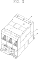
- FIG. 2 is a view illustrating an electromagnetic contactor according to another implementation of the related art
- FIG. 3 is a lateral cross-sectional view of the electromagnetic contactor.
- the frame that protects and fixes all parts of the electromagnetic contactor roughly includes a lower frame 1a, an upper frame 1b, and an arc box 1c.
- the lower frame 1a and the upper frame 1b are fastened with nuts 12 and screws 11, and the arc box 1c is fixed to the upper frame 1b with a fastening member 10 such as a rivet assembly, etc.
- the fastening member 10 used when assembling the arc box 1c has weak fixing force, and thereby damaged or disassembled due to a fault current when a short-circuit accident occurs.
- the present disclosure has been devised to solve the above-described problems, and one aspect of the present disclosure is to provide an electromagnetic contactor capable of preventing an arc box from being separated from a frame.
- An electromagnetic contactor in accordance with one implementation of the present disclosure includes a lower frame, an upper frame coupled to an upper portion of the lower frame, and an arc cover coupled to an upper portion of the upper frame.
- a first coupling part protrudes from one surface of the lower frame such that a fastening member is coupled
- a second coupling part protrudes from one surface of the upper frame and is connected to the first coupling part, such that the fastening member is fastened
- a third coupling part protrudes from one surface of the arc cover and is connected to the second coupling part, such that the fastening member is fastened.
- the fastening member is coupled through the first coupling part, the second coupling part, and the third coupling part.
- the first coupling part has a predetermined length from an upper end portion of the lower frame, and is shorter than a length (height) of the lower frame.
- the second coupling part has a length from an upper end portion to a lower end portion of the upper frame.
- the third coupling part has a predetermined length from a lower end portion of the arc cover, and may be shorter than a length (height) of the arc cover.
- a first fastening hole may be formed vertically through the first coupling part such that the fastening member is coupled, a second fastening hole may be formed vertically through the second coupling part such that the fastening member is coupled, and a third fastening hole may be formed vertically through the third coupling part such that the fastening member is coupled.
- a first auxiliary fastening hole is formed through the first coupling part to be adjacent to the first fastening hole
- a second auxiliary fastening hole is formed through the second coupling part to be adjacent to the second fastening hole
- an auxiliary fastening member is provided to be coupled through the first auxiliary fastening hole and the second auxiliary fastening hole.
- the first coupling part, the second coupling part, and the third coupling part may be formed respectively at the lower frame, the upper frame, and the arc cover, on each of both side portions of one surface thereof.
- the first coupling part, the second coupling part, and the third coupling part may be formed respectively at the lower frame, one surface of the upper frame, and one surface of the arc cover, on each of both opposite surfaces thereof.
- the first coupling part, the second coupling part, and the third coupling part may be formed on a surface where a fixed contact arm is not exposed based on the upper frame.
- a top cover may be coupled to an upper portion of the arc cover.
- the top cover may have a cover fastening hole
- the arc cover may have an inter-phase insulating groove
- a cover fastening member may be provided to be coupled through the cover fastening hole and the inter-phase insulating groove.
- a first coupling part, a second coupling part, and a third coupling part protrudes from an upper frame, a lower frame, and an arc cover, respectively, and a coupling member is provided to be coupled through the first coupling part, the second coupling part, and the third coupling part, which can secure stable coupling force of the arc cover.
- the coupling of the upper frame, the lower frame, and the arc cover is achieved at a time by the coupling member, thereby enhancing efficiency of an assembling operation.
- Auxiliary fastening members for fixing the upper frame and the lower frame can be additionally provided to increase coupling force between the upper frame and the lower frame.
- a cover coupling member may be provided for a top cover disposed on an upper portion of the arc cover, thereby enhancing the coupling force.
- FIGS. 4 and 6 are a perspective view, an exploded perspective view, and a lateral view in a direction A illustrating an enclosure of an electromagnetic contactor in accordance with one implementation of the present disclosure.
- FIG. 7 is a partial lateral view in a direction B in FIG. 4 , and is a partial cross-sectional view taken along the line C-C.
- An electromagnetic contactor includes a lower frame 20, an upper frame 30 coupled to an upper portion of the lower frame 20, and an arc cover 40 coupled to an upper portion of the upper frame 30.
- a first coupling part 22 protrudes from one surface of the lower frame 20 such that a fastening member 70 is fastened thereto
- a second coupling part 32 protrudes from one surface of the upper frame 30 and is connected to the first coupling part 22 such that the fastening member 70 is fastened thereto
- a third coupling part 42 protrudes from one surface of the arc cover 40 and is connected to the second coupling part 32 such that the fastening member 70 is fastened thereto.
- the fastening member 70 is fastened so as to connect the first coupling part 22, the second coupling part 32, and the third coupling part 42.
- Frames 20, 30, and 40 may also be referred to as an enclosure, and may be provided to accommodate and support components of the electromagnetic contactor.
- the frames 20, 30, and 40 include the lower frame 20, the upper frame 30, and the arc cover 40.
- the lower frame is provided.
- the lower frame 20 may be made of an insulating material such as a synthetic resin material.
- the lower frame 20 may have an open upper surface and define an accommodation space therein.
- a flange 21 may protrude from a bottom surface of the lower frame 20.
- the bottom surface of the lower frame 20 may be supported by the ground or an attached portion so as to stably maintain embedded components.
- An accessory device such as an auxiliary contact device 51 may be disposed on one side surface of the lower frame 20.
- a coil assembly 55 may be accommodated inside the lower frame 20.
- the coil assembly 55 may be installed on a coil assembly mounting cassette 53.
- a fixed core 57 having a shape like "E" may be disposed in a central portion and a peripheral portion of the coil assembly 55.
- the first coupling part 22 protrudes from one side surface of the lower frame 20.
- the first coupling part 22 extends downward from an upper end portion of the lower frame 20 by a predetermined length (thickness). In other words, the first coupling part 22 does not extend to a lower end portion of the lower frame 20. That is, the length (thickness) of the first coupling part 22 is shorter than a length (height) of the lower frame 20.
- a first fastening hole 23 may be formed through the first coupling part 22 in a vertical direction (in an up and down direction).
- the fastening member 70 may be coupled to the first fastening hole 23.
- a first auxiliary fastening hole 24 is formed through the first coupling part 22 in the vertical direction.
- the first auxiliary fastening hole 24 may be formed adjacent to the first fastening hole 23.
- the first coupling part 22 and the first fastening hole 23 may be formed at each of both side portions (both end portions) on one surface of the lower frame 20. That is, the first coupling parts 22 and the first fastening holes 23 may be formed as a pair on the one surface. At this time, the first coupling parts 22 and the first fastening holes 23 formed on the both side portions of the one surface may be symmetrical with each other.
- the first coupling part 22 and the first fastening hole 23 may be formed at each of the both side portions (both end portions) of the lower frame 20 that are symmetrical with each other. At this time, the first coupling parts 22 and the first fastening holes 23 formed on the both side portions may be formed symmetrically with each other. That is, the first coupling parts 22 and the first fastening holes 23 may be formed as pairs on both opposite side surfaces of the lower frame 20, respectively.
- a protrusion 25 may protrude upward from one side surface of the lower frame 20.
- the protrusion 25 may be formed on the surface on which the first coupling part 22 protrudes.
- the protrusion 25 may be formed on each of both opposite side surfaces of the lower frame 20.
- the upper frame 30 is disposed.
- the upper frame 30 may be made of an insulating material such as a synthetic resin material.
- the upper frame 30 may have an open lower surface and define an accommodation space therein.
- the crossbar 61 may be installed through the upper frame 30 to be movable up and down. In the case of a plurality of phases, the crossbar may be provided to protrude for each phase. In the case of three phases, the crossbar 61 may be formed in a shape of a trident to protrude for through of the three phases.
- a movable core (not illustrated) may be coupled to a lower portion of the crossbar 61.
- the movable core may be moved downward by being attracted to the fixed core 57, which is magnetized when external power is applied to the coil assembly 55 and a magnetic flux is produced accordingly.
- the crossbar 61 since the crossbar 61 is coupled to the movable core, the crossbar 61 may also be moved downward together.
- a fixed contact arm 65 may be disposed on an upper surface of the upper frame 30.
- the fixed contact arm 65 may be disposed for each phase.
- the fixed contact arms 65 may be classified for each phase into a fixed contact arm disposed at a power source side and a fixed contact arm disposed at a load side.
- a terminal may be formed on an end portion of the fixed contact arm 65. That is, the fixed contact arm 65 may be integrally formed with the terminal.
- An inter-phase insulating wall 67 may be disposed between adjacent fixed contact arms 65.
- the inter-phase insulating wall 67 can prevent arcs generated at the terminal from expanding into adjacent phases.
- the second coupling part 32 protrudes from one side surface of the upper frame 30.
- the surface on which the second coupling part 32 is formed may be a surface on which the fixed contact arm 65 is not exposed.
- the second coupling part 32 has a length (thickness, height) from an upper end portion to a lower end portion of the upper frame 30.
- the second coupling part 32 is formed from the upper end portion to the lower end portion of the upper frame 30, not only on a portion of the upper frame 30, in the vertical (lengthwise) direction. That is, the second coupling part 32 has the same length (thickness) as the length (height) of the upper frame 30.
- a second fastening hole 33 may be formed through the second coupling part 32 in a vertical direction (in an up and down direction).
- the fastening member 70 may be coupled to the second fastening hole 33.
- a second auxiliary fastening hole 34 is formed through the second coupling part 32 in the vertical direction.
- the second auxiliary fastening hole 34 may be formed adjacent to the second fastening hole 33.
- the second coupling part 32 and the first fastening hole 33 may be formed at each of both side portions (both end portions) on one surface of the upper frame 30. That is, the first coupling parts 22 and the first fastening holes 23 may be formed as a pair on the one surface. At this time, the second coupling parts 32 and the second fastening holes 33 formed on the both side portions of the one surface may be symmetrical with each other.
- the second coupling part 32 and the second fastening hole 33 may be formed on both side surfaces of the upper frame 30 that are symmetrical with each other. At this time, the second coupling parts 32 and the second fastening holes 33 formed on the both side portions may be symmetrical with each other. That is, the second coupling parts 32 and the second fastening holes 33 may be formed as pairs on both opposite side surfaces of the upper frame 30, respectively.
- the second coupling part 32 and the second fastening hole 33 may be formed to communicate with the first coupling part 22 and the first fastening hole 23. That is, they may be formed on a surface in the same direction. This surface may be a surface on which the fixed contact arm 65 is not exposed at the upper frame 30.
- a concave portion 35 corresponding to the protrusion 25 of the lower frame 20 may be formed on one side surface of the upper frame 30.
- the concave portion 35 may be formed on each of both opposite side surfaces of the upper frame 30.
- a plurality of fitting portions 37 may protrude from the upper surface of the upper frame 30.
- the fitting portions 37 may be formed on an upper portion of the surface where the fixed contact arm 65 is not exposed.
- a side portion of the arc cover 40 may be fitted into the fitting portions 37.
- the arc cover 40 is disposed.
- the arc cover 40 may be made of an insulating material such as a synthetic resin material.
- the arc cover 40 may have an open lower surface and define an accommodation space therein.
- the crossbar 61 and a movable contact arm may operate with being accommodated in the accommodation space of the arc cover 40.
- a trip button hole 41 may be formed through an upper surface of the arc cover 40. A head of the crossbar 61 may be exposed through the trip button hole 41 to perform a trip operation.
- a plurality of vent holes 45 may be formed through a side surface of the arc cover 40.
- the third coupling part 42 protrudes from one side surface of the arc cover 40.
- the third coupling part 42 has a predetermined length (thickness) from a lower end portion of the arc cover 40.
- the third coupling part 42 does not extend to an upper end portion of the arc cover 40.
- the third coupling part 42 is formed on only a portion of the arc cover 40 in the vertical lengthwise direction, without being formed along an entire length of the arc cover 40. That is, the length (thickness) of the third coupling part 42 is shorter than a length (height) of the arc cover 40.
- a third fastening hole 43 may be formed through the third coupling part 42 in the vertical direction (in the up and down direction).
- the fastening member 70 may be coupled to the third fastening hole 43.
- the third coupling part 42 and the third fastening hole 43 may be formed at each of both side portions (both end portions) on one surface of the arc cover 40. At this time, the third coupling parts 42 and the third fastening holes 43 formed on the both side portions may be symmetrical with each other.
- the third coupling parts 42 and the third fastening holes 43 may be formed respectively on both side surfaces of the arc cover 40 that are symmetrical with each other. At this time, the third coupling parts 42 and the third fastening holes 43 formed on the both side portions may be symmetrical with each other. That is, the third coupling parts 42 and the third fastening holes 43 may be formed as pairs on both opposite side surfaces of the arc cover 40, respectively.
- the third coupling part 42 and the third fastening hole 43 may be formed to communicate with the second coupling part 32 and the second fastening hole 33. That is, they may be formed on a surface in the same direction.
- the fastening member 70 such as a screw and a nut is provided.
- the fastening member 70 is coupled through the first fastening hole 23, the second fastening hole 33, and the third fastening hole 43. Accordingly, the lower frame 20, the upper frame 30, and the arc cover 40 can be fastened by a single operation.
- the arc cover 40 is integrally coupled to the upper frame 30 and the lower frame 20, such coupling can be stably maintained without separation even if an arc is frequently generated.
- a screw member 72 may be configured as an insert nut. The screw member 72 may be inserted into the first coupling part 22 of the lower frame 20.
- An auxiliary fastening member 75 such as a screw may be provided.
- the auxiliary fastening member 75 may be coupled through the first auxiliary fastening hole 24 and the second auxiliary fastening hole 34. Since the upper frame 30 and the lower frame 20 are additionally coupled by the auxiliary fastening member 75, the coupling force between the upper frame 30 and the lower frame 20 can further be increased.
- FIG. 7 is a partial lateral view in a direction B in FIG. 4 , and is a partial cross-sectional view taken along the line C-C.
- FIG. 8 is a disassembled perspective view illustrating an arc cover and a top cover.
- a top cover 50 may be provided.
- the top cover 50 may be coupled to an upper surface of the arc cover 40.
- a button hole 58 connected to the trip button hole 41 may be formed through the top cover 50.
- the head of the crossbar 61 may be exposed through the button hole 58 to perform a trip operation.
- Cover fastening holes 59 may be formed through the top cover 50. Positions at which the cover fastening holes 59 are formed may be portions where phases are in contact with the top cover 50.
- Inter-phase insulating grooves 46 may be formed in the arc cover 40.
- the inter-phase insulating grooves 46 and the cover fastening holes 59 may be disposed to communicate with each other.
- the inter-phase insulating grooves 46 may be stepped.
- Cover fastening members 77 may be disposed.
- the cover fastening members 77 may be coupled through the cover fastening holes 59 and the inter-phase insulating grooves 46.
- the top cover 50 may be stably fastened to the arc cover 40 by the cover fastening members 77.
- the cover fastening member 77 may be configured as a bolt, to be fastened to a nut 79 disposed in a lower portion of the inter-phase insulating groove 46.
Landscapes
- Physics & Mathematics (AREA)
- Electromagnetism (AREA)
- Switch Cases, Indication, And Locking (AREA)
- Breakers (AREA)
Claims (7)
- Elektromagnetisches Schütz, umfassend:einen unteren Rahmen (20);einen oberen Rahmen (30), der mit einem oberen Abschnitt des unteren Rahmens (20) verbunden ist; undeine Lichtbogenabdeckung (40), die mit einem oberen Abschnitt des oberen Rahmens (30) verbunden ist;wobei ein erstes Verbindungsteil (22) von einer Oberfläche des unteren Rahmens (20) vorsteht, damit ein Befestigungselement (70) verbunden werden kann,wobei ein zweites Verbindungsteil (32) von einer Oberfläche des oberen Rahmens (30) vorsteht und mit dem ersten Verbindungsteil (22) verbunden ist, sodass das Befestigungselement (70) befestigt werden kann, undwobei ein drittes Verbindungsteil (42) von einer Oberfläche der Lichtbogenabdeckung (40) vorsteht und mit dem zweiten Verbindungsteil (32) verbunden ist, sodass das Befestigungselement (70) befestigt werden kann, undwobei das Befestigungselement (70) über das erste Verbindungsteil (22), das zweite Verbindungsteil (32) und das dritte Verbindungsteil (42) verbunden ist,dadurch gekennzeichnet, dassdas erste Verbindungsteil (22) eine vorbestimmte Länge von einem oberen Endabschnitt des unteren Rahmens (20) hat und kürzer als eine Länge des unteren Rahmens (20) ist,wobei das zweite Verbindungsteil (32) eine Länge von dem oberen Endabschnitt zu dem unteren Endabschnitt des oberen Rahmens (30) aufweist,wobei das dritte Verbindungsteil (42) eine vorbestimmte Länge von einem unteren Endabschnitt der Lichtbogenabdeckung aufweist und kürzer als eine Länge der Lichtbogenabdeckung (40) ist,dadurch gekennzeichnet, dassein erstes Hilfsbefestigungsloch (24) durch das erste Verbindungsteil (22) ausgebildet ist, ein zweites Hilfsbefestigungsloch (34) durch das zweite Verbindungsteil (32) ausgebildet ist und ein Befestigungshilfselement (75) vorgesehen ist, um durch das erste Hilfsbefestigungsloch (23) und das zweite Hilfsbefestigungsloch (33) verbunden zu werden.
- Elektromagnetisches Schütz nach Anspruch 1, wobei ein erstes Befestigungsloch (23) vertikal durch das erste Verbindungsteil (22) ausgebildet ist, sodass das Befestigungselement (70) verbunden ist, ein zweites Befestigungsloch (33) vertikal durch das zweite Verbindungsteil (32) ausgebildet ist, sodass das Befestigungselement (70) verbunden ist, und ein drittes Befestigungsloch (43) vertikal durch das dritte Verbindungsteil (43) ausgebildet ist, sodass das Befestigungselement (70) verbunden ist.
- Elektromagnetisches Schütz nach Anspruch 2, wobei das erste Hilfsbefestigungsloch (24) durch das erste Verbindungsteil (22) ausgebildet ist, um an das erste Befestigungsloch (23) angrenzend zu sein, wobei das zweite Hilfsbefestigungsloch (34) durch das zweite Verbindungsteil (32) ausgebildet ist, um an das zweite Befestigungsloch (33) angrenzend zu sein.
- Elektromagnetisches Schütz nach Anspruch 1, wobei ein erstes Verbindungsteil (22), ein zweites Verbindungsteil (32) und ein drittes Verbindungsteil (42) jeweils an dem unteren Rahmen (20), dem oberen Rahmen (30) und der Lichtbogenabdeckung (40) an jedem der beiden Seitenabschnitte einer Oberfläche davon ausgebildet sind.
- Elektromagnetisches Schütz nach Anspruch 4, wobei ein erstes Verbindungsteil (22), ein zweites Verbindungsteil (32) und ein drittes Verbindungsteil (42) jeweils an dem unteren Rahmen (20), dem oberen Rahmen (30) und der Lichtbogenabdeckung (40) auf jeder von beiden gegenüberliegenden Oberflächen davon ausgebildet sind.
- Elektromagnetisches Schütz nach Anspruch 5, bei dem das erste Verbindungsteil (22), das zweite Verbindungsteil (32) und das dritte Verbindungsteil (42) auf Oberflächen ausgebildet sind, auf deren Grundlage ein feststehender Kontaktarm (65) nicht freiliegt, basierend auf dem oberen Rahmen (30).
- Elektromagnetisches Schütz nach Anspruch 1, wobei eine obere Abdeckung (50) mit einem oberen Abschnitt der Lichtbogenabdeckung (40) verbunden ist, und
wobei die obere Abdeckung (50) ein Abdeckungs-Befestigungsloch (59) aufweist, die Lichtbogenabdeckung (40) eine Zwischenphasen-Isoliernut (46) aufweist und ein Abdeckungs-Befestigungselement (77) vorgesehen ist, um durch das Abdeckungs-Befestigungsloch (59) und die Zwischenphasenisoliernut (46) verbunden zu werden.
Applications Claiming Priority (2)
| Application Number | Priority Date | Filing Date | Title |
|---|---|---|---|
| KR1020200006826A KR102349755B1 (ko) | 2020-01-17 | 2020-01-17 | 전자접촉기 |
| PCT/KR2020/019062 WO2021145583A1 (ko) | 2020-01-17 | 2020-12-24 | 전자접촉기 |
Publications (3)
| Publication Number | Publication Date |
|---|---|
| EP4092709A1 EP4092709A1 (de) | 2022-11-23 |
| EP4092709A4 EP4092709A4 (de) | 2024-01-31 |
| EP4092709B1 true EP4092709B1 (de) | 2025-05-28 |
Family
ID=76864762
Family Applications (1)
| Application Number | Title | Priority Date | Filing Date |
|---|---|---|---|
| EP20914456.7A Active EP4092709B1 (de) | 2020-01-17 | 2020-12-24 | Elektromagnetisches schütz |
Country Status (5)
| Country | Link |
|---|---|
| US (1) | US12431309B2 (de) |
| EP (1) | EP4092709B1 (de) |
| KR (1) | KR102349755B1 (de) |
| CN (1) | CN114981912B (de) |
| WO (1) | WO2021145583A1 (de) |
Families Citing this family (1)
| Publication number | Priority date | Publication date | Assignee | Title |
|---|---|---|---|---|
| KR102770711B1 (ko) * | 2022-02-22 | 2025-02-24 | 동명대학교산학협력단 | 전자접촉기 |
Family Cites Families (21)
| Publication number | Priority date | Publication date | Assignee | Title |
|---|---|---|---|---|
| US2514913A (en) * | 1946-05-17 | 1950-07-11 | Air Reduction | Multiple switch |
| US3099730A (en) * | 1960-10-18 | 1963-07-30 | Tateishi Kazuma | Magnetic switch |
| US3222476A (en) * | 1963-08-16 | 1965-12-07 | Square D Co | Electromagnetic switch |
| GB1053488A (de) * | 1963-12-26 | |||
| US3453571A (en) * | 1967-08-24 | 1969-07-01 | Cutler Hammer Inc | Electromagnetic relay with convertible switch contact modules |
| EP0310107B1 (de) * | 1987-10-01 | 1992-12-16 | Mitsubishi Denki Kabushiki Kaisha | Koaxialer Anlasser |
| US5278531A (en) * | 1992-08-06 | 1994-01-11 | Eaton Corporation | Molded case circuit breaker having housing elements |
| JPH06124639A (ja) * | 1992-10-08 | 1994-05-06 | Mitsubishi Electric Corp | 回路遮断器 |
| JP3298236B2 (ja) * | 1993-06-01 | 2002-07-02 | 富士電機株式会社 | 回路遮断器の補助カバー締付用ねじ装置 |
| KR200146681Y1 (ko) | 1996-08-24 | 1999-06-15 | 이종수 | 전자접촉기의 보조접점 어셈블리 장착 구조 |
| KR19980035923A (ko) * | 1996-11-15 | 1998-08-05 | 이종수 | 안전장치가 구비된 전자접촉기 |
| KR200150074Y1 (ko) * | 1996-11-30 | 1999-07-01 | 이종수 | 전자접촉기의 베이스와 아크박스의 체결구조 |
| JP3391016B2 (ja) * | 1998-08-25 | 2003-03-31 | 富士電機株式会社 | 電磁接触器 |
| US6377144B1 (en) * | 1999-11-03 | 2002-04-23 | General Electric Company | Molded case circuit breaker base and mid-cover assembly |
| US6208229B1 (en) * | 2000-04-06 | 2001-03-27 | Eaton Corporation | Moulded case power switch housing with removably secured secondary cover |
| US7358837B2 (en) * | 2006-04-12 | 2008-04-15 | Eaton Corporation | Electrical switching apparatus and circuit breaker including a molded enclosure and machine screws reinforcing the same |
| KR200456667Y1 (ko) * | 2007-10-08 | 2011-11-10 | 현대중공업 주식회사 | 전자 접촉기 |
| EP2543057B1 (de) * | 2010-03-04 | 2015-09-09 | Labinal, LLC | Thermisch verwaltete elektromagnetische schaltvorrichtung |
| CN202473769U (zh) * | 2012-01-13 | 2012-10-03 | 浙江正泰电器股份有限公司 | 一种交流接触器 |
| CN105190819A (zh) * | 2013-05-21 | 2015-12-23 | 万高电机及控制装置自动化有限公司 | 电磁开关装置的线圈模块 |
| CN203434091U (zh) | 2013-08-30 | 2014-02-12 | 瑞立集团瑞安汽车零部件有限公司 | 双线圈节能型电磁电源开关 |
-
2020
- 2020-01-17 KR KR1020200006826A patent/KR102349755B1/ko active Active
- 2020-12-24 CN CN202080092698.8A patent/CN114981912B/zh active Active
- 2020-12-24 US US17/793,519 patent/US12431309B2/en active Active
- 2020-12-24 WO PCT/KR2020/019062 patent/WO2021145583A1/ko not_active Ceased
- 2020-12-24 EP EP20914456.7A patent/EP4092709B1/de active Active
Also Published As
| Publication number | Publication date |
|---|---|
| CN114981912A (zh) | 2022-08-30 |
| US20230121694A1 (en) | 2023-04-20 |
| KR20210093087A (ko) | 2021-07-27 |
| KR102349755B1 (ko) | 2022-01-11 |
| US12431309B2 (en) | 2025-09-30 |
| WO2021145583A1 (ko) | 2021-07-22 |
| EP4092709A1 (de) | 2022-11-23 |
| EP4092709A4 (de) | 2024-01-31 |
| CN114981912B (zh) | 2026-01-02 |
Similar Documents
| Publication | Publication Date | Title |
|---|---|---|
| JP5876270B2 (ja) | 電磁接触器 | |
| US10199193B2 (en) | Electromagnetic relay | |
| JP5684650B2 (ja) | 電磁接触器 | |
| CN102687225B (zh) | 用于中压断路器的双稳态磁致动器 | |
| JP5727862B2 (ja) | 電磁接触器 | |
| JP5856426B2 (ja) | 接点装置及びこれを使用した電磁接触器 | |
| JP5778989B2 (ja) | 電磁接触器 | |
| EP0532586B1 (de) | Solenoid betätigte schaltvorrichtung | |
| JP5990090B2 (ja) | 電磁開閉器 | |
| JP5864902B2 (ja) | 電磁接触器の消弧室組立方法 | |
| CN103238198A (zh) | 电磁接触器 | |
| JP2012243591A (ja) | 電磁接触器 | |
| KR102898141B1 (ko) | 릴레이 접촉자 자기차폐 구조 및 릴레이 | |
| CN115798999A (zh) | 直流继电器 | |
| JP2005158711A (ja) | 双安定電磁リレー | |
| US12431309B2 (en) | Electromagnetic contactor | |
| JP2024133031A (ja) | リレー | |
| EP3624156A1 (de) | Verbesserte schützvorrichtungsstruktur mit verbessertem hilfsschalter | |
| JP2017208157A (ja) | 開閉装置 | |
| KR100298331B1 (ko) | 전자접촉기의보조가동접촉자어셈블리 | |
| KR101869722B1 (ko) | 전자접촉기 | |
| KR200494733Y1 (ko) | 전자접촉기 및 이의 단자구조 | |
| CN116417285A (zh) | 一种设有单磁钢辅助灭弧的电磁继电器 | |
| CN117542700A (zh) | 一种可实现多种辅助触点型式的高压直流接触器及转换辅助触头结构 | |
| KR101116386B1 (ko) | 전자개폐장치 |
Legal Events
| Date | Code | Title | Description |
|---|---|---|---|
| STAA | Information on the status of an ep patent application or granted ep patent |
Free format text: STATUS: THE INTERNATIONAL PUBLICATION HAS BEEN MADE |
|
| PUAI | Public reference made under article 153(3) epc to a published international application that has entered the european phase |
Free format text: ORIGINAL CODE: 0009012 |
|
| STAA | Information on the status of an ep patent application or granted ep patent |
Free format text: STATUS: REQUEST FOR EXAMINATION WAS MADE |
|
| 17P | Request for examination filed |
Effective date: 20220728 |
|
| AK | Designated contracting states |
Kind code of ref document: A1 Designated state(s): AL AT BE BG CH CY CZ DE DK EE ES FI FR GB GR HR HU IE IS IT LI LT LU LV MC MK MT NL NO PL PT RO RS SE SI SK SM TR |
|
| DAV | Request for validation of the european patent (deleted) | ||
| DAX | Request for extension of the european patent (deleted) | ||
| A4 | Supplementary search report drawn up and despatched |
Effective date: 20240105 |
|
| RIC1 | Information provided on ipc code assigned before grant |
Ipc: H01H 50/04 20060101AFI20231222BHEP |
|
| GRAP | Despatch of communication of intention to grant a patent |
Free format text: ORIGINAL CODE: EPIDOSNIGR1 |
|
| STAA | Information on the status of an ep patent application or granted ep patent |
Free format text: STATUS: GRANT OF PATENT IS INTENDED |
|
| INTG | Intention to grant announced |
Effective date: 20250102 |
|
| GRAS | Grant fee paid |
Free format text: ORIGINAL CODE: EPIDOSNIGR3 |
|
| GRAA | (expected) grant |
Free format text: ORIGINAL CODE: 0009210 |
|
| STAA | Information on the status of an ep patent application or granted ep patent |
Free format text: STATUS: THE PATENT HAS BEEN GRANTED |
|
| AK | Designated contracting states |
Kind code of ref document: B1 Designated state(s): AL AT BE BG CH CY CZ DE DK EE ES FI FR GB GR HR HU IE IS IT LI LT LU LV MC MK MT NL NO PL PT RO RS SE SI SK SM TR |
|
| P01 | Opt-out of the competence of the unified patent court (upc) registered |
Free format text: CASE NUMBER: APP_19016/2025 Effective date: 20250422 |
|
| REG | Reference to a national code |
Ref country code: GB Ref legal event code: FG4D |
|
| REG | Reference to a national code |
Ref country code: CH Ref legal event code: EP |
|
| REG | Reference to a national code |
Ref country code: IE Ref legal event code: FG4D Ref country code: DE Ref legal event code: R096 Ref document number: 602020052126 Country of ref document: DE |
|
| REG | Reference to a national code |
Ref country code: NL Ref legal event code: MP Effective date: 20250528 |
|
| PG25 | Lapsed in a contracting state [announced via postgrant information from national office to epo] |
Ref country code: ES Free format text: LAPSE BECAUSE OF FAILURE TO SUBMIT A TRANSLATION OF THE DESCRIPTION OR TO PAY THE FEE WITHIN THE PRESCRIBED TIME-LIMIT Effective date: 20250528 Ref country code: FI Free format text: LAPSE BECAUSE OF FAILURE TO SUBMIT A TRANSLATION OF THE DESCRIPTION OR TO PAY THE FEE WITHIN THE PRESCRIBED TIME-LIMIT Effective date: 20250528 |
|
| REG | Reference to a national code |
Ref country code: LT Ref legal event code: MG9D |
|
| PG25 | Lapsed in a contracting state [announced via postgrant information from national office to epo] |
Ref country code: GR Free format text: LAPSE BECAUSE OF FAILURE TO SUBMIT A TRANSLATION OF THE DESCRIPTION OR TO PAY THE FEE WITHIN THE PRESCRIBED TIME-LIMIT Effective date: 20250829 Ref country code: NO Free format text: LAPSE BECAUSE OF FAILURE TO SUBMIT A TRANSLATION OF THE DESCRIPTION OR TO PAY THE FEE WITHIN THE PRESCRIBED TIME-LIMIT Effective date: 20250828 |
|
| PG25 | Lapsed in a contracting state [announced via postgrant information from national office to epo] |
Ref country code: PL Free format text: LAPSE BECAUSE OF FAILURE TO SUBMIT A TRANSLATION OF THE DESCRIPTION OR TO PAY THE FEE WITHIN THE PRESCRIBED TIME-LIMIT Effective date: 20250528 Ref country code: NL Free format text: LAPSE BECAUSE OF FAILURE TO SUBMIT A TRANSLATION OF THE DESCRIPTION OR TO PAY THE FEE WITHIN THE PRESCRIBED TIME-LIMIT Effective date: 20250528 |
|
| PG25 | Lapsed in a contracting state [announced via postgrant information from national office to epo] |
Ref country code: BG Free format text: LAPSE BECAUSE OF FAILURE TO SUBMIT A TRANSLATION OF THE DESCRIPTION OR TO PAY THE FEE WITHIN THE PRESCRIBED TIME-LIMIT Effective date: 20250528 |
|
| PG25 | Lapsed in a contracting state [announced via postgrant information from national office to epo] |
Ref country code: HR Free format text: LAPSE BECAUSE OF FAILURE TO SUBMIT A TRANSLATION OF THE DESCRIPTION OR TO PAY THE FEE WITHIN THE PRESCRIBED TIME-LIMIT Effective date: 20250528 |
|
| PGFP | Annual fee paid to national office [announced via postgrant information from national office to epo] |
Ref country code: FR Payment date: 20250909 Year of fee payment: 6 |
|
| PG25 | Lapsed in a contracting state [announced via postgrant information from national office to epo] |
Ref country code: RS Free format text: LAPSE BECAUSE OF FAILURE TO SUBMIT A TRANSLATION OF THE DESCRIPTION OR TO PAY THE FEE WITHIN THE PRESCRIBED TIME-LIMIT Effective date: 20250828 |
|
| PG25 | Lapsed in a contracting state [announced via postgrant information from national office to epo] |
Ref country code: IS Free format text: LAPSE BECAUSE OF FAILURE TO SUBMIT A TRANSLATION OF THE DESCRIPTION OR TO PAY THE FEE WITHIN THE PRESCRIBED TIME-LIMIT Effective date: 20250928 |
|
| PG25 | Lapsed in a contracting state [announced via postgrant information from national office to epo] |
Ref country code: LV Free format text: LAPSE BECAUSE OF FAILURE TO SUBMIT A TRANSLATION OF THE DESCRIPTION OR TO PAY THE FEE WITHIN THE PRESCRIBED TIME-LIMIT Effective date: 20250528 |
|
| REG | Reference to a national code |
Ref country code: AT Ref legal event code: MK05 Ref document number: 1799130 Country of ref document: AT Kind code of ref document: T Effective date: 20250528 |
|
| PGFP | Annual fee paid to national office [announced via postgrant information from national office to epo] |
Ref country code: DE Payment date: 20250908 Year of fee payment: 6 |
|
| PG25 | Lapsed in a contracting state [announced via postgrant information from national office to epo] |
Ref country code: SM Free format text: LAPSE BECAUSE OF FAILURE TO SUBMIT A TRANSLATION OF THE DESCRIPTION OR TO PAY THE FEE WITHIN THE PRESCRIBED TIME-LIMIT Effective date: 20250528 Ref country code: AT Free format text: LAPSE BECAUSE OF FAILURE TO SUBMIT A TRANSLATION OF THE DESCRIPTION OR TO PAY THE FEE WITHIN THE PRESCRIBED TIME-LIMIT Effective date: 20250528 Ref country code: DK Free format text: LAPSE BECAUSE OF FAILURE TO SUBMIT A TRANSLATION OF THE DESCRIPTION OR TO PAY THE FEE WITHIN THE PRESCRIBED TIME-LIMIT Effective date: 20250528 |
|
| PG25 | Lapsed in a contracting state [announced via postgrant information from national office to epo] |
Ref country code: CZ Free format text: LAPSE BECAUSE OF FAILURE TO SUBMIT A TRANSLATION OF THE DESCRIPTION OR TO PAY THE FEE WITHIN THE PRESCRIBED TIME-LIMIT Effective date: 20250528 |
|
| PG25 | Lapsed in a contracting state [announced via postgrant information from national office to epo] |
Ref country code: EE Free format text: LAPSE BECAUSE OF FAILURE TO SUBMIT A TRANSLATION OF THE DESCRIPTION OR TO PAY THE FEE WITHIN THE PRESCRIBED TIME-LIMIT Effective date: 20250528 |
|
| PG25 | Lapsed in a contracting state [announced via postgrant information from national office to epo] |
Ref country code: SK Free format text: LAPSE BECAUSE OF FAILURE TO SUBMIT A TRANSLATION OF THE DESCRIPTION OR TO PAY THE FEE WITHIN THE PRESCRIBED TIME-LIMIT Effective date: 20250528 |
|
| PG25 | Lapsed in a contracting state [announced via postgrant information from national office to epo] |
Ref country code: IT Free format text: LAPSE BECAUSE OF FAILURE TO SUBMIT A TRANSLATION OF THE DESCRIPTION OR TO PAY THE FEE WITHIN THE PRESCRIBED TIME-LIMIT Effective date: 20250528 |
|
| REG | Reference to a national code |
Ref country code: DE Ref legal event code: R097 Ref document number: 602020052126 Country of ref document: DE |
|
| PG25 | Lapsed in a contracting state [announced via postgrant information from national office to epo] |
Ref country code: RO Free format text: LAPSE BECAUSE OF FAILURE TO SUBMIT A TRANSLATION OF THE DESCRIPTION OR TO PAY THE FEE WITHIN THE PRESCRIBED TIME-LIMIT Effective date: 20250528 |
|
| PLBE | No opposition filed within time limit |
Free format text: ORIGINAL CODE: 0009261 |
|
| STAA | Information on the status of an ep patent application or granted ep patent |
Free format text: STATUS: NO OPPOSITION FILED WITHIN TIME LIMIT |
|
| REG | Reference to a national code |
Ref country code: CH Ref legal event code: L10 Free format text: ST27 STATUS EVENT CODE: U-0-0-L10-L00 (AS PROVIDED BY THE NATIONAL OFFICE) Effective date: 20260409 |
|
| 26N | No opposition filed |
Effective date: 20260303 |