EP4092359B1 - Ablenker für einen kondensator, kondensator damit und kühlersystem - Google Patents
Ablenker für einen kondensator, kondensator damit und kühlersystem Download PDFInfo
- Publication number
- EP4092359B1 EP4092359B1 EP22174602.7A EP22174602A EP4092359B1 EP 4092359 B1 EP4092359 B1 EP 4092359B1 EP 22174602 A EP22174602 A EP 22174602A EP 4092359 B1 EP4092359 B1 EP 4092359B1
- Authority
- EP
- European Patent Office
- Prior art keywords
- deflector
- condenser
- tube section
- fins
- inlet
- Prior art date
- Legal status (The legal status is an assumption and is not a legal conclusion. Google has not performed a legal analysis and makes no representation as to the accuracy of the status listed.)
- Active
Links
Images
Classifications
-
- F—MECHANICAL ENGINEERING; LIGHTING; HEATING; WEAPONS; BLASTING
- F25—REFRIGERATION OR COOLING; COMBINED HEATING AND REFRIGERATION SYSTEMS; HEAT PUMP SYSTEMS; MANUFACTURE OR STORAGE OF ICE; LIQUEFACTION SOLIDIFICATION OF GASES
- F25B—REFRIGERATION MACHINES, PLANTS OR SYSTEMS; COMBINED HEATING AND REFRIGERATION SYSTEMS; HEAT PUMP SYSTEMS
- F25B39/00—Evaporators; Condensers
- F25B39/04—Condensers
-
- F—MECHANICAL ENGINEERING; LIGHTING; HEATING; WEAPONS; BLASTING
- F25—REFRIGERATION OR COOLING; COMBINED HEATING AND REFRIGERATION SYSTEMS; HEAT PUMP SYSTEMS; MANUFACTURE OR STORAGE OF ICE; LIQUEFACTION SOLIDIFICATION OF GASES
- F25B—REFRIGERATION MACHINES, PLANTS OR SYSTEMS; COMBINED HEATING AND REFRIGERATION SYSTEMS; HEAT PUMP SYSTEMS
- F25B1/00—Compression machines, plants or systems with non-reversible cycle
- F25B1/06—Compression machines, plants or systems with non-reversible cycle with compressor of jet type, e.g. using liquid under pressure
-
- F—MECHANICAL ENGINEERING; LIGHTING; HEATING; WEAPONS; BLASTING
- F28—HEAT EXCHANGE IN GENERAL
- F28F—DETAILS OF HEAT-EXCHANGE AND HEAT-TRANSFER APPARATUS, OF GENERAL APPLICATION
- F28F9/00—Casings; Header boxes; Auxiliary supports for elements; Auxiliary members within casings
- F28F9/02—Header boxes; End plates
- F28F9/026—Header boxes; End plates with static flow control means, e.g. with means for uniformly distributing heat exchange media into conduits
- F28F9/0265—Header boxes; End plates with static flow control means, e.g. with means for uniformly distributing heat exchange media into conduits by using guiding means or impingement means inside the header box
-
- F—MECHANICAL ENGINEERING; LIGHTING; HEATING; WEAPONS; BLASTING
- F28—HEAT EXCHANGE IN GENERAL
- F28F—DETAILS OF HEAT-EXCHANGE AND HEAT-TRANSFER APPARATUS, OF GENERAL APPLICATION
- F28F9/00—Casings; Header boxes; Auxiliary supports for elements; Auxiliary members within casings
- F28F9/02—Header boxes; End plates
- F28F9/026—Header boxes; End plates with static flow control means, e.g. with means for uniformly distributing heat exchange media into conduits
- F28F9/028—Header boxes; End plates with static flow control means, e.g. with means for uniformly distributing heat exchange media into conduits by using inserts for modifying the pattern of flow inside the header box, e.g. by using flow restrictors or permeable bodies or blocks with channels
-
- F—MECHANICAL ENGINEERING; LIGHTING; HEATING; WEAPONS; BLASTING
- F25—REFRIGERATION OR COOLING; COMBINED HEATING AND REFRIGERATION SYSTEMS; HEAT PUMP SYSTEMS; MANUFACTURE OR STORAGE OF ICE; LIQUEFACTION SOLIDIFICATION OF GASES
- F25B—REFRIGERATION MACHINES, PLANTS OR SYSTEMS; COMBINED HEATING AND REFRIGERATION SYSTEMS; HEAT PUMP SYSTEMS
- F25B1/00—Compression machines, plants or systems with non-reversible cycle
- F25B1/04—Compression machines, plants or systems with non-reversible cycle with compressor of rotary type
- F25B1/053—Compression machines, plants or systems with non-reversible cycle with compressor of rotary type of turbine type
-
- F—MECHANICAL ENGINEERING; LIGHTING; HEATING; WEAPONS; BLASTING
- F25—REFRIGERATION OR COOLING; COMBINED HEATING AND REFRIGERATION SYSTEMS; HEAT PUMP SYSTEMS; MANUFACTURE OR STORAGE OF ICE; LIQUEFACTION SOLIDIFICATION OF GASES
- F25B—REFRIGERATION MACHINES, PLANTS OR SYSTEMS; COMBINED HEATING AND REFRIGERATION SYSTEMS; HEAT PUMP SYSTEMS
- F25B2339/00—Details of evaporators; Details of condensers
- F25B2339/04—Details of condensers
-
- F—MECHANICAL ENGINEERING; LIGHTING; HEATING; WEAPONS; BLASTING
- F25—REFRIGERATION OR COOLING; COMBINED HEATING AND REFRIGERATION SYSTEMS; HEAT PUMP SYSTEMS; MANUFACTURE OR STORAGE OF ICE; LIQUEFACTION SOLIDIFICATION OF GASES
- F25B—REFRIGERATION MACHINES, PLANTS OR SYSTEMS; COMBINED HEATING AND REFRIGERATION SYSTEMS; HEAT PUMP SYSTEMS
- F25B2500/00—Problems to be solved
- F25B2500/01—Geometry problems, e.g. for reducing size
-
- F—MECHANICAL ENGINEERING; LIGHTING; HEATING; WEAPONS; BLASTING
- F25—REFRIGERATION OR COOLING; COMBINED HEATING AND REFRIGERATION SYSTEMS; HEAT PUMP SYSTEMS; MANUFACTURE OR STORAGE OF ICE; LIQUEFACTION SOLIDIFICATION OF GASES
- F25B—REFRIGERATION MACHINES, PLANTS OR SYSTEMS; COMBINED HEATING AND REFRIGERATION SYSTEMS; HEAT PUMP SYSTEMS
- F25B2500/00—Problems to be solved
- F25B2500/12—Sound
-
- F—MECHANICAL ENGINEERING; LIGHTING; HEATING; WEAPONS; BLASTING
- F25—REFRIGERATION OR COOLING; COMBINED HEATING AND REFRIGERATION SYSTEMS; HEAT PUMP SYSTEMS; MANUFACTURE OR STORAGE OF ICE; LIQUEFACTION SOLIDIFICATION OF GASES
- F25B—REFRIGERATION MACHINES, PLANTS OR SYSTEMS; COMBINED HEATING AND REFRIGERATION SYSTEMS; HEAT PUMP SYSTEMS
- F25B2500/00—Problems to be solved
- F25B2500/13—Vibrations
-
- F—MECHANICAL ENGINEERING; LIGHTING; HEATING; WEAPONS; BLASTING
- F28—HEAT EXCHANGE IN GENERAL
- F28B—STEAM OR VAPOUR CONDENSERS
- F28B1/00—Condensers in which the steam or vapour is separate from the cooling medium by walls, e.g. surface condenser
-
- F—MECHANICAL ENGINEERING; LIGHTING; HEATING; WEAPONS; BLASTING
- F28—HEAT EXCHANGE IN GENERAL
- F28F—DETAILS OF HEAT-EXCHANGE AND HEAT-TRANSFER APPARATUS, OF GENERAL APPLICATION
- F28F2265/00—Safety or protection arrangements; Arrangements for preventing malfunction
- F28F2265/28—Safety or protection arrangements; Arrangements for preventing malfunction for preventing noise
-
- F—MECHANICAL ENGINEERING; LIGHTING; HEATING; WEAPONS; BLASTING
- F28—HEAT EXCHANGE IN GENERAL
- F28F—DETAILS OF HEAT-EXCHANGE AND HEAT-TRANSFER APPARATUS, OF GENERAL APPLICATION
- F28F2265/00—Safety or protection arrangements; Arrangements for preventing malfunction
- F28F2265/30—Safety or protection arrangements; Arrangements for preventing malfunction for preventing vibrations
-
- F—MECHANICAL ENGINEERING; LIGHTING; HEATING; WEAPONS; BLASTING
- F28—HEAT EXCHANGE IN GENERAL
- F28F—DETAILS OF HEAT-EXCHANGE AND HEAT-TRANSFER APPARATUS, OF GENERAL APPLICATION
- F28F2275/00—Fastening; Joining
- F28F2275/06—Fastening; Joining by welding
Definitions
- the present invention relates to the technical field of heat exchange equipment, in particular to a deflector for a condenser, and also relates to a condenser provided with the deflector for a condenser, and a refrigeration system equipped with the condenser.
- a condenser belongs to a kind of heat exchange equipment.
- a refrigeration system composed of basic components such as compressor, condenser, throttle valve and evaporator
- the refrigerant circulates continuously in the system, and exchanges heat with the outside world through its own phase change.
- the compressor compresses the working medium from low-temperature and low-pressure gas into high-temperature and high-pressure gas, and then condenses it into medium-temperature and high-pressure liquid through the condenser.
- a baffle plate is mounted at the position corresponding to the refrigerant inlet port inside the shell of the condenser to reduce the impact force of the high-temperature and high-pressure gas from exhaust pipes of the compressor.
- the baffle plate When the refrigerant gas flow discharged from the compressor passes through the baffle plate, the huge impact force of the gas flow often causes severe vibration of the entire condenser and produces undesired noise.
- US 10 386 130 B2 discloses a a deflector according to the preamble of claim 1.
- a deflector according to claim 1 is provided.
- the second tube section is enlarged at an angle ⁇ between 15-90° with respect to the tube axis.
- the support assembly comprises a plurality of fins, wherein the number of the fins is six, and the fins are arranged symmetrically or at equal intervals on the outer side of the first tube section.
- the bottom of the second tube section is provided with a serrated portion.
- the flow guiding structure and the support assembly are integrally formed.
- the flow guiding structure is made of steel.
- the fins are configured to be fixed at the inlet by welding.
- a condenser provided with the aforementioned deflector for a condenser is further provided.
- a refrigeration system comprising the aforementioned condenser is further provided.
- embodiments of the deflector for a condenser according to the present invention can not only effectively alleviate the impact of the high-temperature and high-pressure gas flow from the compressor, but also help to reduce the vibration of the condenser during operation and thus reduce noise.
- orientation terms such as upper, lower, left, right, front, rear, inner side, outer side, top and bottom mentioned or possibly mentioned in this specification are defined relative to the configurations illustrated in the respective drawings. They are relative concepts, so they may change accordingly according to their different locations and different states of use. Therefore, these and other orientation terms shall not be construed as restrictive terms.
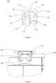
- FIG 1 it schematically illustrates the structure of an embodiment of a deflector for a condenser.
- the condenser 200 has an inlet communicated with exhaust pipes 300 of the compressor (not shown), and a deflector 100 is provided at the inlet to guide the refrigerant gas flow from the compressor.
- the deflector 100 may be composed of a flow guiding structure 110 and a support assembly 120.
- the flow guiding structure 110 has a first tube section 111 and a second tube section 112, wherein the first tube section 111 is straight and the second tube section 112 is expanded, that is, the diameter of the second tube section 112 is gradually enlarged.
- the bottom of the first tube section 111 is almost flush with the inlet portion of the condenser 200, while the second tube section 112 is positioned below the first tube section 111 and extending into the condenser 200 when mounted in place.
- the support assembly 120 is used to fix the flow guiding structure 110 at the inlet.
- the high-temperature and high-pressure gas from the exhaust pipes 300 of the compressor is divided into two parts when flowing through the flow guiding structure 110: only a part of the gas flow passes through the interior of the first tube section 111, and then impinges on a baffle plate 400 fixed near the inlet of the condenser 200, so the vibration generated when the gas flow impinges on the baffle plate 400 can be effectively reduced; another part of the gas flow passes through the outer side of the first tube section 111, and this part of the gas flow, through the flared tube below, i.e., the second tube section 112, changes direction and diffuses to the length direction of the condenser 200 (as shown by the arrow in FIG 2 ). As such, the flow guiding structure 110 can make the gas flow entering the condenser 200 more evenly distributed.
- the second tube section 112 is enlarged at an angle ⁇ between 15-90° with respect to the tube axis, so as to better help to evenly disperse the gas flow to the inside of the condenser 200.
- the support assembly 120 comprises a plurality of fins.
- the number of the fins is six, and the fins are arranged symmetrically on the outer side of the first tube section 111, or arranged at equal intervals on the outer side of the first tube section 111.
- the number of the fins is not limited to six, but can be two, three, four, five or others, as long as the fins can ensure the strength of the support assembly and fix the flow guiding structure 110 on the exhaust pipes 300.
- the fins can be fixed at the inlet by welding or other means.
- the second tube section 112 is designed with two notches 113 symmetrically arranged thereon, as shown in FIG 1 .
- the bottom of the second tube section 112 may be provided with a serrated portion 114, so that the pressure pulsation inside the condenser 200 can be attenuated to a certain extent, thereby reducing aerodynamic noise.
- the serrated portion 114 can be designed in a regular shape, such as a corrugated shape as shown in FIG 1 , or can be designed in an irregular shape, such as a special shape.
- the support assembly 120 and the flow guiding structure 110 may be designed to be integrally formed.
- the support assembly can also be mounted on the flow guiding structure as an additional component.
- the deflector for a condenser can effectively reduce the impact force of the high-temperature and high-pressure gas flow from the compressor, and help reduce the severe vibration caused by the internal structure of the condenser.
- the noise generated due to vibration can change its propagation direction by means of the flow guiding structure of the deflector, thereby effectively reducing the noise level of the condenser.
- a condenser may be provided with the aforementioned deflector for a condenser. Since the deflector is provided inside the condenser, the condenser is less likely to generate undesired noise and vibration during operation. According to the analysis of the engineering simulation software CFD (Computational Fluid Dynamics), the condenser using the deflector can achieve a more uniform temperature distribution along the heat exchange tubes, thereby achieving better heat transfer performance.
- CFD Computer Fluid Dynamics
- a refrigeration system may be equipped with the aforementioned condenser.
- the refrigeration system comprises a cooling tower, a water chiller, a pumping device and the like that are connected by pipelines, wherein, the water chiller is composed of components such as compressor, condenser, throttling device and evaporator.
- the water chiller is composed of components such as compressor, condenser, throttling device and evaporator.
- a condenser provided with the aforementioned deflector can effectively reduce vibration and noise, so it is highly recommended to apply the aforementioned condenser to various refrigeration systems.
- the deflector for a condenser, a condenser provided with the deflector for a condenser and a refrigeration system equipped with the condenser.
- These individual examples are only used to illustrate the principle of the present invention and the implementations thereof, but not to limit the present invention.
- Those skilled in the art may, without departing from the scope of the present invention as defined by the claims, make various modifications and improvements.
- the deflector may be made of steel or other high-strength materials.
Landscapes
- Engineering & Computer Science (AREA)
- Physics & Mathematics (AREA)
- Thermal Sciences (AREA)
- Mechanical Engineering (AREA)
- General Engineering & Computer Science (AREA)
- Heat-Exchange Devices With Radiators And Conduit Assemblies (AREA)
Claims (10)
- Ablenker (100) für einen Kondensator, wobei der Kondensator (200) einen Einlass aufweist, der mit Abgasrohren (300) eines Kompressors verbunden ist, und der Ablenker (100) dazu konfiguriert ist, an dem Einlass bereitgestellt zu sein, wobei der Ablenker Folgendes umfasst:eine Strömungsführungsstruktur (110), die einen ersten Rohrabschnitt (111) und einen zweiten Rohrabschnitt (112) mit zunehmendem Durchmesser aufweist, wobei der zweite Rohrabschnitt (112) unter dem ersten Rohrabschnitt (111) positioniert und dazu konfiguriert ist, sich in den Kondensator (200) zu erstrecken, wenn er an Ort und Stelle montiert ist, undeine Stützbaugruppe (120) zum Befestigen der Strömungsführungsstruktur (110) an dem Einlass,wobei der Ablenker derart konfiguriert ist, dass, wenn der Ablenker an Ort und Stelle montiert ist, mindestens ein Teil des Kältemittelgasstroms durch ein Inneres des ersten Rohrabschnitts (111) strömt und mindestens ein anderer Teil des Kältemittelgasstroms durch eine Außenseite des ersten Rohrabschnitts (111) strömt,wobei der Ablenker dadurch gekennzeichnet ist, dass der zweite Rohrabschnitt (112) zwei symmetrisch daran angeordnete Kerben (113) umfasst.
- Ablenker (100) nach Anspruch 1, wobei ein Durchmesser d des ersten Rohrabschnitts (111) durch die folgende Formel erlangt wird:

- Ablenker (100) nach Anspruch 2, wobei der zweite Rohrabschnitt (112) in einem Winkel θ zwischen 15-90 ° in Bezug auf die Rohrachse vergrößert ist.
- Ablenker (100) nach einem der Ansprüche 1 bis 3, wobei die Stützbaugruppe (120) eine Vielzahl von Rippen umfasst, wobei die Anzahl der Rippen sechs beträgt und wobei die Rippen symmetrisch oder in gleichen Abständen an der Außenseite des ersten Rohrabschnitts (111) angeordnet sind.
- Ablenker nach Anspruch 4, wobei die Rippen dazu konfiguriert sind, durch Schweißen an dem Einlass befestigt zu werden.
- Ablenker (100) nach einem der Ansprüche 1 bis 5, wobei ein Boden des zweiten Rohrabschnitts (112) mit einem gezahnten Abschnitt (114) bereitgestellt ist.
- Ablenker (100) nach einem der Ansprüche 1 bis 6, wobei die Strömungsführungsstruktur (110) und die Trägerbaugruppe (120) einstückig gebildet sind.
- Ablenker (100) nach einem der Ansprüche 1 bis 7, wobei der Ablenker (100) aus Stahl hergestellt ist.
- Kondensator (200), wobei der Kondensator (200) mit dem Ablenker (100) nach einem der Ansprüche 1-8 bereitgestellt ist.
- Kältesystem, wobei das Kältesystem den Kondensator (100) nach Anspruch 9 umfasst.
Applications Claiming Priority (1)
| Application Number | Priority Date | Filing Date | Title |
|---|---|---|---|
| CN202110558042.7A CN115371297A (zh) | 2021-05-21 | 2021-05-21 | 用于冷凝器的导流装置、具有其的冷凝器及制冷系统 |
Publications (2)
| Publication Number | Publication Date |
|---|---|
| EP4092359A1 EP4092359A1 (de) | 2022-11-23 |
| EP4092359B1 true EP4092359B1 (de) | 2024-12-25 |
Family
ID=81750689
Family Applications (1)
| Application Number | Title | Priority Date | Filing Date |
|---|---|---|---|
| EP22174602.7A Active EP4092359B1 (de) | 2021-05-21 | 2022-05-20 | Ablenker für einen kondensator, kondensator damit und kühlersystem |
Country Status (3)
| Country | Link |
|---|---|
| US (1) | US12235024B2 (de) |
| EP (1) | EP4092359B1 (de) |
| CN (1) | CN115371297A (de) |
Family Cites Families (40)
| Publication number | Priority date | Publication date | Assignee | Title |
|---|---|---|---|---|
| US1498408A (en) * | 1922-08-12 | 1924-06-17 | Leigh W Morris | Flooded shell-type condenser |
| US3180405A (en) * | 1959-03-11 | 1965-04-27 | Itt | Condensers |
| SU203708A1 (ru) | 1966-03-12 | 1967-10-09 | Ф. А. Фролов, И. А. Ганичев , Н. И. Молодцов Центральный научно исследовательский дизельный институт | Кожухотрубчатый теплообменник |
| US3696883A (en) | 1971-12-13 | 1972-10-10 | Harry M Devane | Sound muting assembly for gas flow duct systems |
| DE2706980A1 (de) | 1977-02-18 | 1978-08-24 | Rudolf Klefisch | Lenkungsduese fuer gasverbrennung in rohren |
| US4667770A (en) | 1986-10-02 | 1987-05-26 | Devane Harry M | Sound attenuator |
| SE463223B (sv) | 1989-02-17 | 1990-10-22 | Svenska Rotor Maskiner Ab | Skruvrotormaskin med ljuddaempare |
| US5465783A (en) * | 1994-03-04 | 1995-11-14 | Fedco Automotive Components Company, Inc. | Sacrificial erosion bridge for a heat exchanger |
| US5507151A (en) | 1995-02-16 | 1996-04-16 | American Standard Inc. | Noise reduction in screw compressor-based refrigeration systems |
| US6027072A (en) * | 1998-08-05 | 2000-02-22 | The Boeing Company | Payload chamber cooling system |
| US7011180B2 (en) | 2002-09-18 | 2006-03-14 | Savant Measurement Corporation | System for filtering ultrasonic noise within a fluid flow system |
| JP3958302B2 (ja) | 2004-04-28 | 2007-08-15 | 東京ラヂエーター製造株式会社 | 熱交換器 |
| US7578659B2 (en) | 2005-01-31 | 2009-08-25 | York International Corporation | Compressor discharge muffler |
| US8136980B2 (en) | 2006-07-27 | 2012-03-20 | Komax Systems, Inc. | Meter flow conditioner |
| DE102006035755A1 (de) | 2006-08-01 | 2008-02-07 | Contitech Kühner Gmbh & Cie. Kg | Vorrichtung zur Schalldämpfung in einem Rohrkanal |
| WO2008143834A1 (en) | 2007-05-18 | 2008-11-27 | Mccrometer, Inc. | Flow straightening apparatus |
| US8240367B2 (en) * | 2007-06-28 | 2012-08-14 | Exxonmobil Research And Engineering Company | Plate heat exchanger port insert and method for alleviating vibrations in a heat exchanger |
| US8276653B2 (en) * | 2008-03-28 | 2012-10-02 | Saudi Arabian Oil Company | Raised overlapped impingement plate |
| DE102011013340A1 (de) | 2010-12-30 | 2012-07-05 | Linde Aktiengesellschaft | Verteileinrichtung und Wärmetauschervorrichtung |
| US9057391B2 (en) | 2012-05-17 | 2015-06-16 | Canada Pipeline Accessories, Co. Ltd. | Reflector for fluid measurement system |
| JP5896876B2 (ja) | 2012-10-17 | 2016-03-30 | 日立アプライアンス株式会社 | 冷媒分配器及びこれを備えた冷凍サイクル装置 |
| DE102014201908A1 (de) * | 2014-02-03 | 2015-08-06 | Duerr Cyplan Ltd. | Verfahren zur Führung eines Fluidstroms, Strömungsapparat und dessen Verwendung |
| JP6787647B2 (ja) | 2014-09-08 | 2020-11-18 | 三菱重工サーマルシステムズ株式会社 | ターボ冷凍機 |
| CN104832247B (zh) | 2015-04-29 | 2017-05-03 | 麦克维尔空调制冷(武汉)有限公司 | 一种用于螺杆式机组的排气消声器 |
| JP6629627B2 (ja) | 2016-02-22 | 2020-01-15 | 三菱重工業株式会社 | 騒音低減構造及び過給装置 |
| JP6621187B2 (ja) | 2016-02-26 | 2019-12-18 | 三菱重工コンプレッサ株式会社 | 冷却装置、圧縮機システム |
| US10746441B2 (en) | 2016-03-07 | 2020-08-18 | Daikin Applied Americas Inc. | Heat exchanger |
| JP6821321B2 (ja) | 2016-04-15 | 2021-01-27 | 三菱重工サーマルシステムズ株式会社 | 凝縮器、これを備えたターボ冷凍装置 |
| JP6670197B2 (ja) | 2016-07-25 | 2020-03-18 | 荏原冷熱システム株式会社 | 圧縮式冷凍機用凝縮器 |
| JP6957857B2 (ja) * | 2016-10-13 | 2021-11-02 | 株式会社Ihi | 流体分散装置及び熱処理装置 |
| EP3309494B1 (de) * | 2016-10-13 | 2021-04-28 | HS Marston Aerospace Limited | Wärmetauscher |
| JP2018124024A (ja) | 2017-02-02 | 2018-08-09 | 三菱重工サーマルシステムズ株式会社 | 凝縮器 |
| US10612823B2 (en) | 2017-02-03 | 2020-04-07 | Daikin Applied Americas Inc. | Condenser |
| CN111630329B (zh) | 2017-10-10 | 2022-12-02 | 江森自控科技公司 | 加热、通风、空调和制冷系统、冷凝器及其设计方法 |
| EP3476470B1 (de) * | 2017-10-26 | 2022-11-09 | ALFA LAVAL OLMI S.p.A. | Rohrbündelausrüstung mit verteilungsvorrichtung |
| CN208332761U (zh) | 2018-01-16 | 2019-01-04 | 开利公司 | 用于冷凝器的导流板、具有其的冷凝器及制冷系统 |
| JP6929806B2 (ja) | 2018-02-21 | 2021-09-01 | 株式会社鷺宮製作所 | 流量制御弁および冷凍サイクルシステム |
| JP7414577B2 (ja) | 2020-02-21 | 2024-01-16 | 三菱重工コンプレッサ株式会社 | 冷却装置 |
| CN212299563U (zh) | 2020-08-03 | 2021-01-05 | 珠海格力电器股份有限公司 | 冷凝器和空调设备 |
| JP2023035173A (ja) | 2021-08-31 | 2023-03-13 | 株式会社ニチリン | 消音装置 |
-
2021
- 2021-05-21 CN CN202110558042.7A patent/CN115371297A/zh active Pending
-
2022
- 2022-05-17 US US17/746,411 patent/US12235024B2/en active Active
- 2022-05-20 EP EP22174602.7A patent/EP4092359B1/de active Active
Also Published As
| Publication number | Publication date |
|---|---|
| CN115371297A (zh) | 2022-11-22 |
| US20220373231A1 (en) | 2022-11-24 |
| EP4092359A1 (de) | 2022-11-23 |
| US12235024B2 (en) | 2025-02-25 |
Similar Documents
| Publication | Publication Date | Title |
|---|---|---|
| EP3511654B1 (de) | Kondensator mit führungspaneel und kühlsystem | |
| AU2011215523B2 (en) | Heat exchanger for air conditioner | |
| EP2241849A2 (de) | Mikrokanalwärmetauscher nach Rohr-Rippen-Block Bauart mit besonderer Führung des Rücklaufrohres | |
| CN103649668A (zh) | 板式换热器和冷冻循环装置 | |
| US20210190331A1 (en) | Refrigerant distributor, heat exchanger, and air-conditioning apparatus | |
| JPWO2019077744A1 (ja) | 空気調和機 | |
| EP2982924A1 (de) | Wärmetauscher | |
| JP6230769B1 (ja) | 熱交換器 | |
| EP4092359A1 (de) | Ablenker für einen kondensator, kondensator damit und kühlersystem | |
| US11598582B2 (en) | Shell-and-tube heat exchanger and air conditioning system | |
| US20210010727A1 (en) | Heat exchanger | |
| CN208282655U (zh) | 一种管壳式换热器 | |
| KR20110030302A (ko) | 공기 조화기 | |
| CN103574774B (zh) | 空调机 | |
| JP2024120080A (ja) | 冷凍システム用のコンパクト熱交換器アセンブリ | |
| JP2012102928A (ja) | 熱交換器およびこれを備えた車両用空調装置 | |
| US11906215B2 (en) | Water chamber for condenser, condenser having it and chiller system | |
| CN116972454A (zh) | 一种换热系统 | |
| KR102726788B1 (ko) | 튜브-핀 어셈블리 | |
| EP3885690B1 (de) | Wärmetauscher und kühlzyklusvorrichtung | |
| WO2022048251A1 (zh) | 组合式换热器 | |
| CN116336046B (zh) | 一种液压系统用消声装置 | |
| JPH11337275A (ja) | シェルアンドチューブ式凝縮器 | |
| CN218544896U (zh) | 基于涡流结构和扰流环的换热管内流动形态可控蒸发器 | |
| CN211120135U (zh) | 一种新型汽车冷凝器 |
Legal Events
| Date | Code | Title | Description |
|---|---|---|---|
| PUAI | Public reference made under article 153(3) epc to a published international application that has entered the european phase |
Free format text: ORIGINAL CODE: 0009012 |
|
| STAA | Information on the status of an ep patent application or granted ep patent |
Free format text: STATUS: THE APPLICATION HAS BEEN PUBLISHED |
|
| AK | Designated contracting states |
Kind code of ref document: A1 Designated state(s): AL AT BE BG CH CY CZ DE DK EE ES FI FR GB GR HR HU IE IS IT LI LT LU LV MC MK MT NL NO PL PT RO RS SE SI SK SM TR |
|
| STAA | Information on the status of an ep patent application or granted ep patent |
Free format text: STATUS: REQUEST FOR EXAMINATION WAS MADE |
|
| 17P | Request for examination filed |
Effective date: 20230522 |
|
| RBV | Designated contracting states (corrected) |
Designated state(s): AL AT BE BG CH CY CZ DE DK EE ES FI FR GB GR HR HU IE IS IT LI LT LU LV MC MK MT NL NO PL PT RO RS SE SI SK SM TR |
|
| GRAP | Despatch of communication of intention to grant a patent |
Free format text: ORIGINAL CODE: EPIDOSNIGR1 |
|
| STAA | Information on the status of an ep patent application or granted ep patent |
Free format text: STATUS: GRANT OF PATENT IS INTENDED |
|
| RIC1 | Information provided on ipc code assigned before grant |
Ipc: F28F 9/22 20060101ALI20240801BHEP Ipc: F25B 39/04 20060101AFI20240801BHEP |
|
| INTG | Intention to grant announced |
Effective date: 20240822 |
|
| GRAS | Grant fee paid |
Free format text: ORIGINAL CODE: EPIDOSNIGR3 |
|
| GRAA | (expected) grant |
Free format text: ORIGINAL CODE: 0009210 |
|
| STAA | Information on the status of an ep patent application or granted ep patent |
Free format text: STATUS: THE PATENT HAS BEEN GRANTED |
|
| AK | Designated contracting states |
Kind code of ref document: B1 Designated state(s): AL AT BE BG CH CY CZ DE DK EE ES FI FR GB GR HR HU IE IS IT LI LT LU LV MC MK MT NL NO PL PT RO RS SE SI SK SM TR |
|
| REG | Reference to a national code |
Ref country code: GB Ref legal event code: FG4D |
|
| REG | Reference to a national code |
Ref country code: CH Ref legal event code: EP |
|
| REG | Reference to a national code |
Ref country code: DE Ref legal event code: R096 Ref document number: 602022008997 Country of ref document: DE |
|
| REG | Reference to a national code |
Ref country code: IE Ref legal event code: FG4D |
|
| REG | Reference to a national code |
Ref country code: LT Ref legal event code: MG9D |
|
| PG25 | Lapsed in a contracting state [announced via postgrant information from national office to epo] |
Ref country code: HR Free format text: LAPSE BECAUSE OF FAILURE TO SUBMIT A TRANSLATION OF THE DESCRIPTION OR TO PAY THE FEE WITHIN THE PRESCRIBED TIME-LIMIT Effective date: 20241225 |
|
| PG25 | Lapsed in a contracting state [announced via postgrant information from national office to epo] |
Ref country code: FI Free format text: LAPSE BECAUSE OF FAILURE TO SUBMIT A TRANSLATION OF THE DESCRIPTION OR TO PAY THE FEE WITHIN THE PRESCRIBED TIME-LIMIT Effective date: 20241225 |
|
| PG25 | Lapsed in a contracting state [announced via postgrant information from national office to epo] |
Ref country code: BG Free format text: LAPSE BECAUSE OF FAILURE TO SUBMIT A TRANSLATION OF THE DESCRIPTION OR TO PAY THE FEE WITHIN THE PRESCRIBED TIME-LIMIT Effective date: 20241225 |
|
| PG25 | Lapsed in a contracting state [announced via postgrant information from national office to epo] |
Ref country code: NO Free format text: LAPSE BECAUSE OF FAILURE TO SUBMIT A TRANSLATION OF THE DESCRIPTION OR TO PAY THE FEE WITHIN THE PRESCRIBED TIME-LIMIT Effective date: 20250325 |
|
| PG25 | Lapsed in a contracting state [announced via postgrant information from national office to epo] |
Ref country code: LV Free format text: LAPSE BECAUSE OF FAILURE TO SUBMIT A TRANSLATION OF THE DESCRIPTION OR TO PAY THE FEE WITHIN THE PRESCRIBED TIME-LIMIT Effective date: 20241225 Ref country code: GR Free format text: LAPSE BECAUSE OF FAILURE TO SUBMIT A TRANSLATION OF THE DESCRIPTION OR TO PAY THE FEE WITHIN THE PRESCRIBED TIME-LIMIT Effective date: 20250326 |
|
| PG25 | Lapsed in a contracting state [announced via postgrant information from national office to epo] |
Ref country code: RS Free format text: LAPSE BECAUSE OF FAILURE TO SUBMIT A TRANSLATION OF THE DESCRIPTION OR TO PAY THE FEE WITHIN THE PRESCRIBED TIME-LIMIT Effective date: 20250325 |
|
| REG | Reference to a national code |
Ref country code: NL Ref legal event code: MP Effective date: 20241225 |
|
| PG25 | Lapsed in a contracting state [announced via postgrant information from national office to epo] |
Ref country code: NL Free format text: LAPSE BECAUSE OF FAILURE TO SUBMIT A TRANSLATION OF THE DESCRIPTION OR TO PAY THE FEE WITHIN THE PRESCRIBED TIME-LIMIT Effective date: 20241225 |
|
| REG | Reference to a national code |
Ref country code: AT Ref legal event code: MK05 Ref document number: 1754458 Country of ref document: AT Kind code of ref document: T Effective date: 20241225 |
|
| PG25 | Lapsed in a contracting state [announced via postgrant information from national office to epo] |
Ref country code: SM Free format text: LAPSE BECAUSE OF FAILURE TO SUBMIT A TRANSLATION OF THE DESCRIPTION OR TO PAY THE FEE WITHIN THE PRESCRIBED TIME-LIMIT Effective date: 20241225 |
|
| PG25 | Lapsed in a contracting state [announced via postgrant information from national office to epo] |
Ref country code: PL Free format text: LAPSE BECAUSE OF FAILURE TO SUBMIT A TRANSLATION OF THE DESCRIPTION OR TO PAY THE FEE WITHIN THE PRESCRIBED TIME-LIMIT Effective date: 20241225 |
|
| PGFP | Annual fee paid to national office [announced via postgrant information from national office to epo] |
Ref country code: DE Payment date: 20250423 Year of fee payment: 4 |
|
| PG25 | Lapsed in a contracting state [announced via postgrant information from national office to epo] |
Ref country code: ES Free format text: LAPSE BECAUSE OF FAILURE TO SUBMIT A TRANSLATION OF THE DESCRIPTION OR TO PAY THE FEE WITHIN THE PRESCRIBED TIME-LIMIT Effective date: 20241225 |
|
| PG25 | Lapsed in a contracting state [announced via postgrant information from national office to epo] |
Ref country code: IS Free format text: LAPSE BECAUSE OF FAILURE TO SUBMIT A TRANSLATION OF THE DESCRIPTION OR TO PAY THE FEE WITHIN THE PRESCRIBED TIME-LIMIT Effective date: 20250425 |
|
| PG25 | Lapsed in a contracting state [announced via postgrant information from national office to epo] |
Ref country code: PT Free format text: LAPSE BECAUSE OF FAILURE TO SUBMIT A TRANSLATION OF THE DESCRIPTION OR TO PAY THE FEE WITHIN THE PRESCRIBED TIME-LIMIT Effective date: 20250428 |
|
| PG25 | Lapsed in a contracting state [announced via postgrant information from national office to epo] |
Ref country code: EE Free format text: LAPSE BECAUSE OF FAILURE TO SUBMIT A TRANSLATION OF THE DESCRIPTION OR TO PAY THE FEE WITHIN THE PRESCRIBED TIME-LIMIT Effective date: 20241225 |
|
| PGFP | Annual fee paid to national office [announced via postgrant information from national office to epo] |
Ref country code: FR Payment date: 20250423 Year of fee payment: 4 |
|
| PG25 | Lapsed in a contracting state [announced via postgrant information from national office to epo] |
Ref country code: RO Free format text: LAPSE BECAUSE OF FAILURE TO SUBMIT A TRANSLATION OF THE DESCRIPTION OR TO PAY THE FEE WITHIN THE PRESCRIBED TIME-LIMIT Effective date: 20241225 Ref country code: AT Free format text: LAPSE BECAUSE OF FAILURE TO SUBMIT A TRANSLATION OF THE DESCRIPTION OR TO PAY THE FEE WITHIN THE PRESCRIBED TIME-LIMIT Effective date: 20241225 |
|
| PG25 | Lapsed in a contracting state [announced via postgrant information from national office to epo] |
Ref country code: SK Free format text: LAPSE BECAUSE OF FAILURE TO SUBMIT A TRANSLATION OF THE DESCRIPTION OR TO PAY THE FEE WITHIN THE PRESCRIBED TIME-LIMIT Effective date: 20241225 |
|
| PG25 | Lapsed in a contracting state [announced via postgrant information from national office to epo] |
Ref country code: CZ Free format text: LAPSE BECAUSE OF FAILURE TO SUBMIT A TRANSLATION OF THE DESCRIPTION OR TO PAY THE FEE WITHIN THE PRESCRIBED TIME-LIMIT Effective date: 20241225 |
|
| PG25 | Lapsed in a contracting state [announced via postgrant information from national office to epo] |
Ref country code: IT Free format text: LAPSE BECAUSE OF FAILURE TO SUBMIT A TRANSLATION OF THE DESCRIPTION OR TO PAY THE FEE WITHIN THE PRESCRIBED TIME-LIMIT Effective date: 20241225 |
|
| PG25 | Lapsed in a contracting state [announced via postgrant information from national office to epo] |
Ref country code: SE Free format text: LAPSE BECAUSE OF FAILURE TO SUBMIT A TRANSLATION OF THE DESCRIPTION OR TO PAY THE FEE WITHIN THE PRESCRIBED TIME-LIMIT Effective date: 20241225 |
|
| REG | Reference to a national code |
Ref country code: DE Ref legal event code: R097 Ref document number: 602022008997 Country of ref document: DE |
|
| PG25 | Lapsed in a contracting state [announced via postgrant information from national office to epo] |
Ref country code: DK Free format text: LAPSE BECAUSE OF FAILURE TO SUBMIT A TRANSLATION OF THE DESCRIPTION OR TO PAY THE FEE WITHIN THE PRESCRIBED TIME-LIMIT Effective date: 20241225 |
|
| PLBE | No opposition filed within time limit |
Free format text: ORIGINAL CODE: 0009261 |
|
| STAA | Information on the status of an ep patent application or granted ep patent |
Free format text: STATUS: NO OPPOSITION FILED WITHIN TIME LIMIT |
|
| REG | Reference to a national code |
Ref country code: CH Ref legal event code: L10 Free format text: ST27 STATUS EVENT CODE: U-0-0-L10-L00 (AS PROVIDED BY THE NATIONAL OFFICE) Effective date: 20251105 |
|
| 26N | No opposition filed |
Effective date: 20250926 |
|
| REG | Reference to a national code |
Ref country code: CH Ref legal event code: H13 Free format text: ST27 STATUS EVENT CODE: U-0-0-H10-H13 (AS PROVIDED BY THE NATIONAL OFFICE) Effective date: 20251223 |
|
| PG25 | Lapsed in a contracting state [announced via postgrant information from national office to epo] |
Ref country code: LU Free format text: LAPSE BECAUSE OF NON-PAYMENT OF DUE FEES Effective date: 20250520 |
|
| PG25 | Lapsed in a contracting state [announced via postgrant information from national office to epo] |
Ref country code: CH Free format text: LAPSE BECAUSE OF NON-PAYMENT OF DUE FEES Effective date: 20250531 |
|
| REG | Reference to a national code |
Ref country code: BE Ref legal event code: MM Effective date: 20250531 |
|
| PG25 | Lapsed in a contracting state [announced via postgrant information from national office to epo] |
Ref country code: MC Free format text: LAPSE BECAUSE OF FAILURE TO SUBMIT A TRANSLATION OF THE DESCRIPTION OR TO PAY THE FEE WITHIN THE PRESCRIBED TIME-LIMIT Effective date: 20241225 |
|
| PG25 | Lapsed in a contracting state [announced via postgrant information from national office to epo] |
Ref country code: IE Free format text: LAPSE BECAUSE OF NON-PAYMENT OF DUE FEES Effective date: 20250520 |
|
| PG25 | Lapsed in a contracting state [announced via postgrant information from national office to epo] |
Ref country code: BE Free format text: LAPSE BECAUSE OF NON-PAYMENT OF DUE FEES Effective date: 20250531 |